Embed Size (px)
Citation preview
Richard M. Bionta
XTOD Overview [email protected]
October 12, 2004UCRL-PRES-XXXXX
X Ray Transport, Optics, and Diagnostics, Overview
Facility Advisory Committee Meeting
October 12-13, 2004
This work was performed under the auspices of the U.S. Department of Energy by the University of California, Lawrence Livermore National Laboratory under Contract No. W-7405-Eng-48.
Richard M. Bionta
XTOD Overview [email protected]
October 12, 2004UCRL-PRES-XXXXX
Outline
Overall Scope
General Goals
Technical Highlights
Risks
Plans including the Continuing Resolution
Conclusions

Richard M. Bionta
XTOD Overview [email protected]
October 12, 2004UCRL-PRES-XXXXX
XTOD Transports Photons from e- Dump to FEH
UndulatorHall
Electron Dump
Front End Enclosure
Near Experimental
Hall
X-Ray Tunnel
Far Experimental
HallElectron Transport
Linac

Richard M. Bionta
XTOD Overview [email protected]
October 12, 2004UCRL-PRES-XXXXX
Fastclosevalve
Slit A
Muonshield
Gas Attenuator
SolidAttenuator
Slit B
PPS
Muonshield
Direct ImagerIndirect Imager
Comissioning:Spectrometer,Total Energy
PPS
ElectronBeam
PhotonBeam
Electron Dump
Front End Enclosure
NEH1.5 Scope: Front End Enclosure/ Near
Experimental Hall
Flipper Mirror
Richard M. Bionta
XTOD Overview [email protected]
October 12, 2004UCRL-PRES-XXXXX
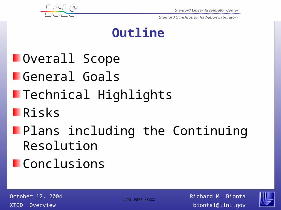
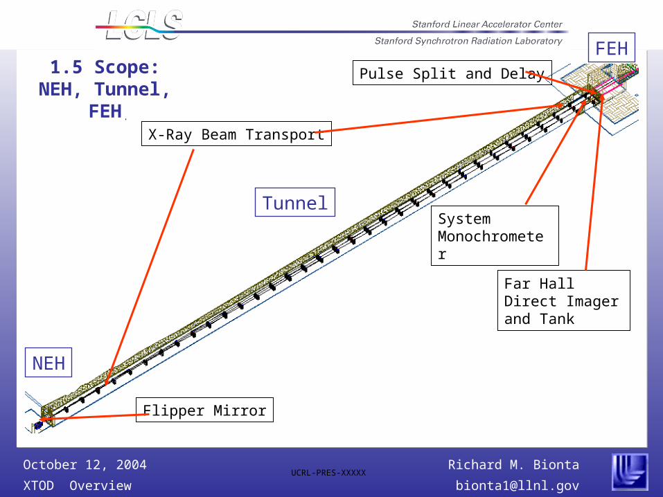
Flipper Mirror
X-Ray Beam Transport
Pulse Split and Delay
Far Hall Direct Imager and Tank
System Monochrometer
FEH
Tunnel
NEH
1.5 Scope: NEH, Tunnel, FEH

Richard M. Bionta
XTOD Overview [email protected]
October 12, 2004UCRL-PRES-XXXXX
XTOD Goals
Provide vacuum path from end of undulator to hutches in Far Hall with capability of attenuating beam to synchrotron levels.
Provide necessary diagnostics to commission the LCLS and monitor its performance.
Detect X-Ray Photons in Far Hall.
Demonstrate detection and optical techniques that would be useful to users.

Richard M. Bionta
XTOD Overview [email protected]
October 12, 2004UCRL-PRES-XXXXX
Main Imaging Diagnostic: Scintillator/Microscope
AdvantagesAdjustable resolution to 1 m.
X-Ray sensor decoupled from CCD
DisadvantagePlaced directly in beam
CCDCamera
MicroscopeObjective
LSO or YAG:Ce crystal prism assembly
X-ray beam

Richard M. Bionta
XTOD Overview [email protected]
October 12, 2004UCRL-PRES-XXXXX
Direct Imager(Placed directly in
beam)
Indirect Imager
(Sees only a low intensity reflection)
Turbo pump
BeIsolation
valve
Indirect Imager sees low intensity reflection
Richard M. Bionta
XTOD Overview [email protected]
October 12, 2004UCRL-PRES-XXXXX
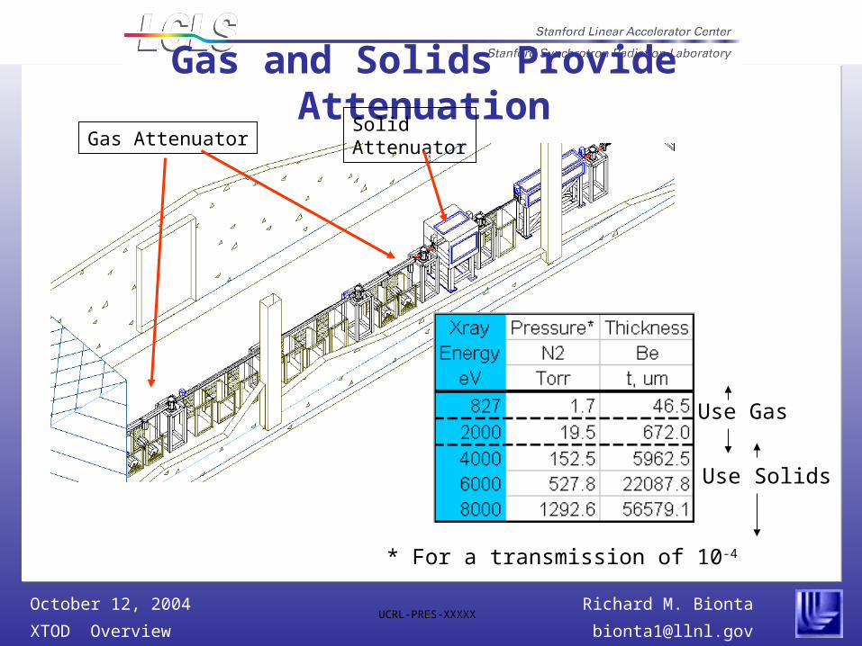
Gas and Solids Provide Attenuation
Autocad
Gas AttenuatorSolidAttenuator
Use Gas
Use Solids
* For a transmission of 10-4

Richard M. Bionta
XTOD Overview [email protected]
October 12, 2004UCRL-PRES-XXXXX
XTOD Risks
Technical risks listed in registry include attenuator performance and instrument backgrounds (mitigated by modularity, redundancy and placement)
Funding profile requires significant design and even conceptual design efforts required when funding commences (CR may help)
Designs and concepts based on theoretical calculations of beam characteristics (current work)
Richard M. Bionta
XTOD Overview [email protected]
October 12, 2004UCRL-PRES-XXXXX
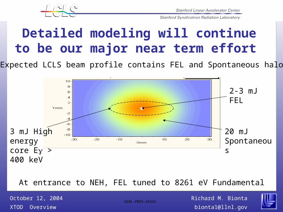
2-3 mJ FEL
20 mJ Spontaneous
3 mJ High energy core E > 400 keV
Detailed modeling will continue to be our major near term effort
At entrance to NEH, FEL tuned to 8261 eV Fundamental
Expected LCLS beam profile contains FEL and Spontaneous halo

Richard M. Bionta
XTOD Overview [email protected]
October 12, 2004UCRL-PRES-XXXXX
Spontaneous halo has rich spectral and spatial structure
0 < E < 10 keV 7.6 < E < 9.0 keV 10 < E < 20 keV 20 < E < 27 keV
20 mm
20 m
m
Near-Field Spontaneous Radiation Patterns in FEE, at position of gas attenuator (88 m from End-of-Undulator)
Richard M. Bionta
XTOD Overview [email protected]
October 12, 2004UCRL-PRES-XXXXX
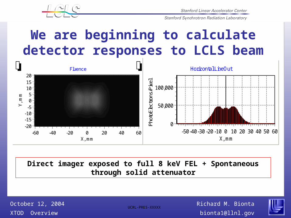
We are beginning to calculate detector responses to LCLS beam
Horizontal LineOut
X, mm6050403020100-10-20-30-40-50
Pho
toE
lect
rons
/Pix
el
100,000
50,000
0
Direct imager exposed to full 8 keV FEL + Spontaneous through solid attenuator
Fluence
X, mm6040200-20-40-60
Y, m
m
20151050
-5-10-15-20
Richard M. Bionta
XTOD Overview [email protected]
October 12, 2004UCRL-PRES-XXXXX
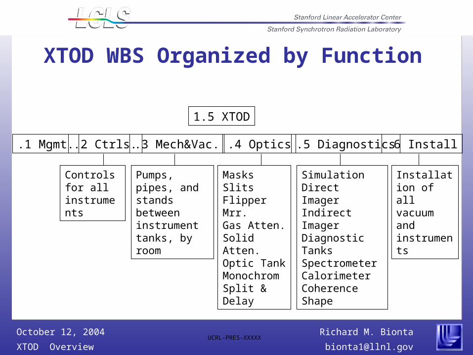
XTOD WBS Organized by Function
1.5 XTOD
.1 Mgmt. .2 Ctrls. .3 Mech&Vac. .4 Optics .5 Diagnostics
Controls for all instruments
Pumps, pipes, and stands between instrument tanks, by room
MasksSlitsFlipper Mrr.Gas Atten.Solid Atten.Optic TankMonochromSplit & Delay
.6 Install
SimulationDirect ImagerIndirect ImagerDiagnostic TanksSpectrometerCalorimeterCoherenceShape
Installation of all vacuum and instruments

Richard M. Bionta
XTOD Overview [email protected]
October 12, 2004UCRL-PRES-XXXXX
Schedule emphasizes early completion of commissioning diagnostics
Controls
Mechanical and Vacuum
Front End Enclosure(FEE)
Near Experimental Hall
Tunnel #
Far Experimental Hall #
Facility Optical Systems
Fixed Mask FEE
Slits/Collimator A FEE
Slits/Collimator B FEE
Gas Attenuator FEE
Solid Attenuator FEE
Crystals and Gratings
Crystal Monochromator FEH
Pulse Split and delay FEH
Diagnostics
Modeling and Simulation
Direct Scintillator Imager
Indirect Imager
Imaging Diagnostic Tank #
Comissioning Diagnostic Tank #
Total Energy Measurement
Spectrometer
20082004 2005 2006 2007
Richard M. Bionta
XTOD Overview [email protected]
October 12, 2004UCRL-PRES-XXXXX
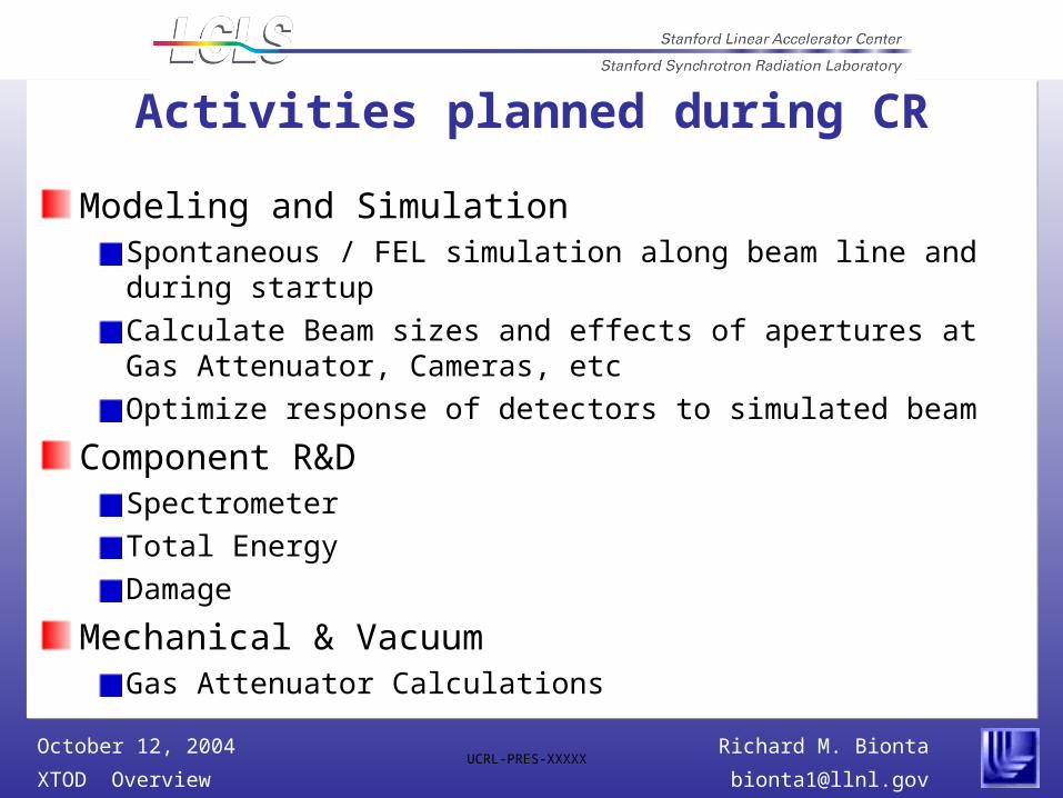
Activities planned during CR
Modeling and SimulationSpontaneous / FEL simulation along beam line and during startup
Calculate Beam sizes and effects of apertures at Gas Attenuator, Cameras, etc
Optimize response of detectors to simulated beam
Component R&DSpectrometer
Total Energy
Damage
Mechanical & VacuumGas Attenuator Calculations

Richard M. Bionta
XTOD Overview [email protected]
October 12, 2004UCRL-PRES-XXXXX
Activities after CR
Detailed Design of FEE in preparation for construction in FY06
Mech. & Vac. through Near HallSlitDirect Imager
R&D & PrototypeGas attenuatorTotal EnergySpectrometerIndirect Imager
Richard M. Bionta
XTOD Overview [email protected]
October 12, 2004UCRL-PRES-XXXXX
Summary
XTOD transports x-ray beam to users and provides optics and diagnostics for LCLS commissioning and monitoringBasic imaging diagnostics and attenuator systems understood and supported by calculations and prototypes. The development of the other instruments will proceed in a serial fashion with priority given to commissioning diagnostics Beam models now exist allowing detailed modeling of the instrumentation. This will proceed during the Continuing Resolution.XTOD will be ready for serious R&D and Engineering effort after the CR in preparation for procurement and fabrication in FY06