Embed Size (px)
Citation preview

t
J.
! l
IU Ll'iA 3q~
UILU-ENG .. 73-2005
~~ 3CIVIL ENGINEERING STUDIES STRUCTURAL RESEARCH SERIES NO. 398
UN E RIBBE SL BS
C E TR TED l
Civil BI06 C. t;" Univc:I'd:L Urbana 9
By
T. ATTAJARUSIT
W. L. GAMBLE
Conducted by
5
THE STRUCTURAL RESEARCH LABORATORY
DEPARTMENT OF CIVil ENGINEERING
ENGINEERING EXPERIMENT STATION
UNIVERSITY OF ILLINOIS AT URBANA-CHAMPAIGN
UNIVERSITY OF ILLINOIS
URBANA, IlUN.OIS
MAY 1973
BIBLIOGRAPHIC DATA 11. Report No. SHEET UILU-ENG-73-2005
Ribben Slabs Under Concentrated Loads
7. A.uchor(s)
T. Attajarusit and W. L. Gamble 9. Pcrfllrll1ing Organization Name and Address
Department of Civil Engineering University of Illinois 2209 Civil Engineering Building Urbana, Illinois 61801
3. Recipient's Accession No.
5. Report Date May 1973
6.
8. Performing Organiz.a tion Re rt No. SRS-398
10. Project/Task/Work Unit No.
11. Contract/Gram No.
~--------------------------------------------------------------4---------------------~ 12. Sponsoring Organization Name and Address
Department of Civil Engineering 'University of Illinois
13. Type of Report & Period Covered
2209 Civil Engineering Building Urbana, Illinois 61801
15. Supplementary Notes '
16. Abstracts
Final Report 14.
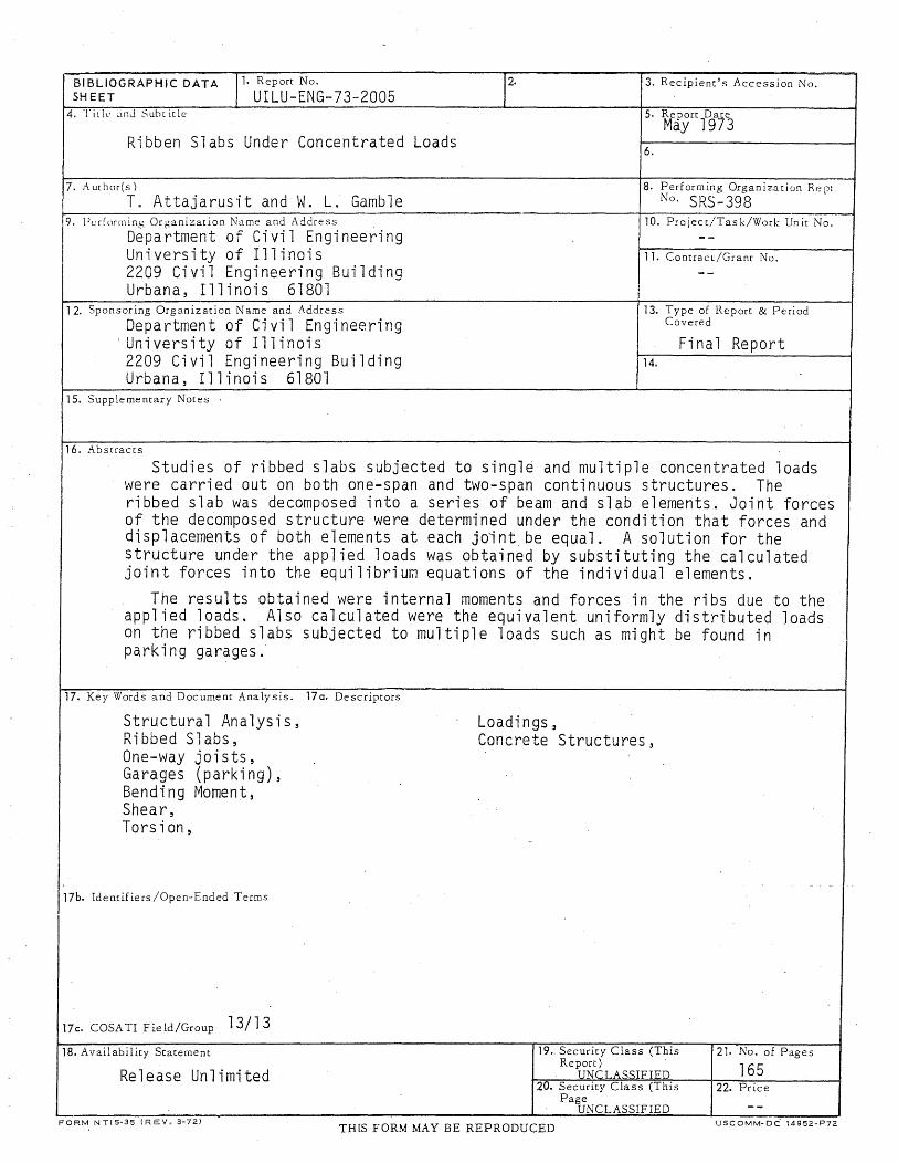
Studies of ribbed slabs subjected to single and multiple concentrated loads were carried out on both one-span and two-span continuous structures. The ribbed slab was decomposed into a series of beam and slab elements. Joint forces of the decomposed structure were determined under the condition that forces and displacements of both elements at each joint. be equal. A solution for the structure under the applied loads was obtained by substituting the calculated joint forces into the equilibrium equations of the individual elements.
The results obtained were internal moments and forces in the ribs due to the applied loads. Also calculated were the equivalent uniformly distributed loads on the ribbed slabs subjected to multiple loads such as might be found in parking garages.
17. Key Words and Document AnalY$is. 170. Descriptors
Structural Analysis, Loadings, Ribbed Slabs, Concrete Structures, One-way joists, Garages (parking), Bending Moment, Shear, Torsion,
17b. Identifiers/Open-Ended Terms
17c. COSATI Field/Group 13/13 18. Availability Statement
Release Unlimited
FORM NTIS-35 (REV. 3-72)
19 .. Security Class (This Report) .
UNCLASSIFIED 20. Security Class (This
Page UNCLASSIFIED
TH [S FORM MAY BE REPRODUCED
21. No. of Pages
165 22. Price
USCOMM-DC 14952-P72


iii
ACKNOWLEDGMENT
The author wishes to express his appreciation and sincere thanks
to his advisor, Dr. William L. Gamble, Associate Professor of Civil Engi
neering, for his invaluable suggestions and supervision throughout this
study.
The author also wishes to thank Dr .. Chester P. Siess, Professor
of Civil Engineering, for his helpful suggestions at the beginning of this
study.


Chapter
1
2
3
4
iv
TABLE OF CONTENTS
INTRODUCTION .
1 . 1 General. 1.2 Previous Studies 1.3 Object and Scope. . 1.4 The Typical Ribbed Slab. 1.5 Selected Parameters. 1.6 Notation.
METHOD OF ANALYSIS.
2. 1 Genera 1. . 2.2 Assumptions. . . . 2.3 One-Span Ribbed Slab. 2.4 Two-Span Ribbed Slab. 2.5 Multiple Loads. . . . 2.6 Acturacy of the Analysis
BEHAVIOR OF RIBBED SLABS UNDER A SINGLE CONCENTRATED LOAD .
3. 1 General. .. .• 3.2 Moment, Shear, and Torsion Diagrams. 3.3 Moment Envelopes and Influence Lines
for Moment at Midspan and Influence Lines for Shear and Torsion at Support.
3.4 Moment Distribution and Moment Envelope Across the Sp~n '. . .
3.5 Effects of Torsional Stiffness on Moment, Shear, and Torsion. .
3.6 Effects of Hand b/a on Moment, Shear, and Torsion • . . . .
3.7 Effects of Hand b/a on Influence Lines for Torsional Moment at the Support, and the Maximum Torsion.
RIBBED SLABS UNDER MULTIPLE LOADS.
Page
1 .
1 2 4 5 6 8
12
12 12 13 16 18 20
23
23 24
29
35
37
38
46
48
4.1 General. . . . . . . . . . . .. 48 4.2 Moment, 'Shear, and Torsional Moment Diagrams. 49 4.3 Multiple Loads for Maximum Moment and 'Shear • 51 4.4 Multiple Loads for Maximum Torsional Moment. 60 4.5 Variations of Maximum Moment, Shear,
and Torsional Moment,' with Hand b/a 65 4.6 Effects of a Stiffer Edge Rib. 68

Chapter
5
6
v
DISCUSSION AND RECOMMENDATIONS .
5.1 General. . 5.2 Discussion and Comparison. 5.3 General Remarks 5.4 Recommendations
SUMMARY AND CONCLUSIONS
6.1 General Outline of the Investigation 6.2 General Conclusions .
LIST OF REFERENCES
Page
72
72 72 77 78
79
79 80
84

Table
3.1
3.2
4.1
4.2
4.3
5.1
5.2
5.3
5.4
5.5
5.6
5.7
5.8
5.9
vi
LIST OF TABLES
DIMENSIONS AND PARAMETERS OF THE VARIOUS RIBBED SLABS STUDIED. . . . .
PARAMETERS AND DIMENSIONS OF THE RIBBED SLABS FOR THE STUDY OF THE EFFECTS OF TORSIONAL STIFFNESS ON MOMENT, SHEAR AND TORS ION . ...
MAXIMUM SIMPLE BEAM MOMENT AND SHEAR VS. SPAN.
MAXIMUM DEFLECTIONS OF ONE-SPAN RIBBED SLABS DUE TO MULTIPLE LOADS FOR MAXIMUM MOMENT
MAXIMUM DEFLECTIONS OF TWO-SPAN RIBBED SLABS DUE TO MULTIPLE LOADS FOR MAXIMUM POSITIVE MOMENT
EQUIVALENT UNIFORMLY DISTRIBUTED LOADS FOR ONE-SPAN RIBBED SLABS .
EQUIVALENT UNIFORMLY DISTRIBUTED LOADS ON -TWO-SPAN RIBBED SLABS. .
MAXIMUM TORSIONS AT THE SUPPORT OF ONE-SPAN RIBBED SLABS. ...
SHEARS ACCOMPANYING THE MAXIMUM TORSIONS AT THE SUPPORT OF ONE-SPAN RIBBED SLABS. .
MAXIMUM TORSIONS AT THE EXTERIOR SUPPORT OF TWO-SPAN RIBBED SLABS. ...
SHEARS ACCOMPANYING THE MAXIMUM TORSIONS AT THE EXTERIOR SUPPORT OF TWO-SPAN RIBBED SLABS.
MAXIMUM TORSIONS AT THE 0.95 SPAN LOCATION IN TWO-SPAN RIBBED SLABS. ., .
SHEAR_ACCOMPANYING THE MAXIMUM TORSIONS AT THE 0.95 SPAN LOCATION IN TWO-SPAN RIBBED SLABS
NEGATIVE BENDING MOMENTS ACCOMPANYING THE MAX1MUM TORSIONS AT THE 0.95 SPAN LOCATION IN TWO-SPAN RIBBED SLABS. . . . .
Page
86
87
88
89
89
90
91
92
92
93
93
94
94
·95

Table
5.10
5.11
vii
TORSIONS ACCOMPANYING THE MAXIMUM SHEARS AT THE EXTERIOR SUPPORT IN TWO-SPAN RIBBED SLABS .
TORSIONS ACCOMPANYING THE MAXIMUM SHEARS AT THE 0.95 SPAN LOCATION IN TWO-SPAN RIBBED SLABS .
Page
95
95

Figure
1 • 1
2. 1
3.1
3.2
3.3
3.4
3.5 .
3.6
3.7
viii
LIST OF FIGURES
TYPICAL RIBBED SLABS AND CROSS SECTIONS .
INTERNAL FORCES AT THE JUNCTION OF BEAM AND SLAB ELEMENTS, AND ON A SMALL ELEMENT OF BEAM .
MOMENT, SHEAR, AND TORSION DIAGRAMS' FOR A ONE-SPAN RIBBED SLAB DUE TO A SINGLE LOAD AT MIDSPAN ON THE EDGE AND CENTER RIBS.
, MOMENT, SHEAR, AND TORSION DIAGRAMS FOR A TWO-SPAN RIBBED SLAB DUE TO A SINGLE LOAD AT ONE MIDSPAN ON THE EDGE AND CENTER RIBS .
THE INTERPRETATION OF THE LOADING EFFECTS ON THE RIBS. . · .
THE INTERPRETATION OF REACTIONS AND COUPLES AT THE INTERIOR SUPPORT. . .
INFLUENCE LINES FOR MOMENT AT MIDSPAN AND MOMENT ENVELOPES FOR A ONE-SPAN RIBBED SLAB DUE TO A LOAD MOVING ON THE EDGE AND CENTER RIBS .
INFLUENCE LINES FOR MOMENT AT MIDSPAN, AND MOMENT ENVELOPES FOR A TWO-SPAN RIBBED SLAB DUE TO A LOAD MOVING ON THE EDGE AND CENTER RIBS .
INFLUENCE LINES FOR SHEAR AT THE SUPPORT OF A ONE-SPAN RIBBED SLAB DUE TO A LOAD MOVING ON THE EDGE AND CENTER RIBS.
3.8 INFLUENCE LINES FOR SHEAR AT THE EXTERIOR SUPPORT AND AT THE 0.95 SPAN LOCATION OF 'A TWO-SPAN RIBBED SLAB DUE TO A LOAD MOVING ON THE EDGE AND CENTER RIBS .
3.9
3.10
INFLUENCE LINES FOR TORSION AT THE SUPPORT OF A ONE-SPAN RIBBED SLAB DUE TO A LOAD MOVING ON THE EDGE AND CENTER RIBS.
INFLUENCE LINES FOR TORSION AT THE EXTERIOR SUPPORT AND AT THE 0.95 SPAN LOCATION OF A TWO-SPAN RIBBED SLAB DUE TO A LOAD MOVING ON THE EDGE AND CENTER RIBS . .
Page
96
97
98
99
101
102
103
104
105
, f"\C IUU
107
108

ix
Figure
3.11 MOMENT ENVELOPES AND MOMENT DISTRIBUTIONS AT MIDSPAN OF VARIOUS RIBS OF A ONE-SPAN RIBBED SLAB WITH THE REGULAR AND STIFFENED EDGE RIBS
Page
DUE TO A LOAD MOVING ALONG MIDSPAN. 109
3.12 POSITIVE AND NEGATIVE MOMENT ENVELOPES AND MOMENT DISTRIBUTIONS AT MIDSPAN AND AT THE INTERIOR SUPPORT OF VARIOUS RIBS OF A TWOSPAN RIBBED SLAB DUE TO A LOAD MOVING ALONG MIDSPAN. 110
3.13 EFFECTS OF TORSIONAL STIFFNESS ON MOMENT, SHEAR AND TORSION. . 111
3.14 MOMENT DISTRIBUTIONS AT MIDSPAN OF ONE-SPAN RIBBED SLABS DUE TO SINGLE LOADS AT MIDSPAN ON THE EDGE AND CENTER RIBS. . . . . 112
3.15 POSITIVE MOMENT DISTRIBUTIONS AT MIDSPAN OF TWO-SPAN RIBBED SLABS DUE TO SINGLE LOADS AT MIDSPAN OF THE EDGE AND CENTER RIBS.- 113
3.16 NEGATIVE MOMENT DISTRIBUTIONS AT THE INTERIOR SUPPORT OF TWO-SPAN RIBBED SLABS DUE TO SINGLE LOADS AT MIDSPAN ON THE EDGE AND CENTER RIBS. 114
3.17 SHEAR DISTRIBUTIONS AT THE SUPPORT OF ONESPAN RIBBED SLABS DUE TO SINGLE LOADS AT MIDSPAN ON THE EDGE AND CENTER RIBS. 115
3.18 SHEAR DISTRIBUTIONS AT THE EXTERIOR SUPPORT OF THE LOADED SPAN OF TWO-SPAN-RIBBED SLABS DUE TO SINGLE LOADS AT MIDSPAN ON THE EDGE AND CENTER RIBS .. 116
3.19 SHEAR DISTRIBUTIONS AT THE 0.95 SPAN LOCATION OF THE LOADED SPAN OF TWO-SPAN RIBBED SLABS DUE TO SINGLE LOADS AT MIDSPAN ON THE EDGE AND CENTER RIBS . . 117
3.20 TORSIONAL MOMENT DISTRIBUTIONS AT THE SUPPORT OF ONE-SPAN RIBBED SLABS DUE TO SINGLE LOADS AT MIDSPAN ON THE EDGE AND CENTER RIBS. . . 118
·3.21 TORSIONAL MOMENT DISTRIBUTIONS AT THE EXTERIOR SUPPORT OF THE LOADED SPAN OF TWO-RIBBED SLABS DUE TO SINGLE LOADS AT MIDSPAN ON THE EDGE AND CENTER RIBS.. ... . . . 119

Fi gure
3.22
3.23
3.24
3.25
3.26
3.27
3.28
3.29
3.30
4.1
4.2
x
TORSIONAL MOMENT DISTRIBUTIONS AT THE 0.95 SPAN LOCATION OF THE LOADED SPAN OF TWO-SPAN RIBBED SLABS DUE TO SINGLE LOADS AT MIDSPAN ON THE EDGE AND CENTER RIBS. .. .,
VARIATIONS OF MAXIMUM MOMENT WITH HAND b!a FOR ONE-SPAN RIBBED SLABS UNDER SINGLE LOADS AT MIDSPAN ON THE EDGE AND CENTER RIBS. .
VARIATIONS OF MAXIMUM POSITIVE AND NEGATIVE MOMENTS WITH HAND b/a· FOR TWO-SPAN RIBBED SLABS UNDER SINGLE LOADS AT MIDSPAN ON THE EDGE AND CENTER RIBS . .....
VARIATIONS OF MAXIMUM SHEAR AT THE SUPPORT WITH HAND b/a FOR bNE-SPAN RIBBED SLABS UNDER SINGLE LOADS AT MIDSPAN ON THE EDGE AND CENTER RIBS.. ..... .
VARIATIONS OF MAXIMUM SHEAR AT THE EXTERIOR SUPPORT AND 0.95 SPAN LOCATION WITH HAND b/a FOR TWO-SPAN RIBBED SLABS UNDER SINGLE LOADS AT MIDSPAN ON THE EDGE AND CENTER RIBS. .
VARIATIONS OF MAXIMUM TORSION AT THE SUPPORT WITH HAND b/a FOR ONE-SPAN RIBBED SLABS UNDER SINGLE LOADS AT MIDSPAN ON THE EDGE AND CENTER RIBS. . .. . . .
VARIATIONS OF MAXIMUM TORSION AT THE EXTERIOR SUPPORT AND 0.95 SPAN LOCATION WITH HAND b/a FOR TWO-SPAN RIBBED SLABS UNDER SINGLE LOADS AT MIDSPAN ON THE EDGE AND CENTER RIBS. .
INFLUENCE LINES FOR TORSION AT THE SUPPORT OF VARIOUS ONE-SPAN RIBBED SLABS DUE TO A LOAD MOVING ON THE EDGE AND CENTER RIBS. .
VARIATIONS OF MAXIMUM TORSION AT THE SUPPORT WITH HAND b/a FOR ONE-SPAN RIBBED SLABS UNDER SINGLE LOADS ON THE EDGE AND CENTER RIBS ..
LOADING SYSTEMS FOR MAXIMUM BENDING MOMENTS, SHEARS, AND TORSIONAL MOMENTS . .
BENDING MOMENT, SHEAR, AND TORSIONAL MOMENT DIAGRAMS OF A ONE-SPAN RIBBED SLAB DUE TO MULTIPLE LOADS. . . .. .
Page
120
121
122
123
124
125
126
127
128
129
133

Fi gure
4.3
4.4
4.5
4.6
4.7
4.8
4.9
4.10
4. 11
4. 12
4. 13
xi
BENDING MOMENT, SHEAR, AND TORSIONAL MOMENT DIAGRAMS OF A TWO-SPAN RIBBED SLAB DUE TO MULTIPLE LOADS .
MOMENT DISTRIBUTIONS AT MIDSPAN OF ONESPAN RIBBED SLABS DUE TO MULTIPLE LOADS FOR MAXIMUM MOMENT.
SHEAR DISTRIBUTIONS AT THE SUPPORT OF ONE-SPAN RIBBED SLABS DUE TO MULTIPLE LOADS FOR MAXIMUM MOMENT.
TORSIONAL MOMENT DISTRIBUTIONS AT THE SUPPORT OF ONE-SPAN RIBBED SLABS DUE TO MULTIPLE LOADS FOR MAXIMUM MOMENT.
POSITIVE MOMENT DISTRIBUTIONS AT THE 0.44 SPAN LOCATION OF TWO-RIBBED SLABS DUE TO MULTIPLE LOADS FOR MAXIMUM POSITIVE MOMENT.
NEGATIVE MOMENT DISTRIBUTIONS AT THE INTERIOR SUPPORT OF TWO-SPAN RIBBED SLABS DUE TO MULTIPLE LOADS FOR MAXIMUM NEGATIVE MOMENT .
SHEAR DISTRIBUTIONS AT THE EXTERIOR SUPPORT OF TWO-SPAN RIBBED SLABS DUE TO MULTIPLE LOADS FOR MAXIMUM POSITIVE MOMENT.
TORSIONAL MOMENT DISTRIBUTIONS AT THE EXTERIOR SUPPORT OF TWO-SPAN RIBBED SLABS DUE TO MULTIPLE LOADS FOR MAXIMUM POSITIVE MOMENT. ..
SHEAR DISTRIBUTIONS AT THE 0.95 SPAN LOCATION OF TWO-SPAN RIBBED SLABS DUE TO MULTIPLE LOADS FOR MAXIMUM POSITIVE MOMENT.
TORSIONAL MOMENT DISTRIBUTIONS AT THE 0.95 SPAN LOCATIONS OF TWO-SPAN RIBBED SLABS DUE TO MULTIPLE LOADS FOR MAXIMUM POSITIVE MOMENT.
SHEAR DISTRIBUTIONS AT THE 0.95 SPAN LOCATION OF TWO-SPAN RIBBED SLABS DUE TO MULTIPLE LOADS FOR MAXIMUM NEGATIVE MOMENT .
Page
134
136
137
138
139
140
141
142
143
144
145

Figure
4.14
4. 15
4.16
4.17
4.18
4. 19
4.20
4.21
4.22
4.23
4.24
xii
TORSIONAL MOMENT DISTRIBUTIONS AT THE 0.95 SPAN LOCATION OF TWO-SPAN RIBBED SLABS DUE TO MULTIPLE LOADS FOR MAXIMUM NEGATIVE MOMENT
RELATIONSHIPS OF THE MAXIMUM DEFLECTION COEFFICIENT WITH HAND bja ...
TORSIONAL MOMENT DISTRIBUTIONS AT THE SUPPORT OF ONE-SPAN RIBBED SLABS DUE TO MULTIPLE LOADS FOR MAXIMUM TORSION.
SHEAR DISTRIBUTIONS AT THE SUPPORT OF ONE-SPAN RIBBED SLABS DUE TO MULTIPLE LOADS FOR MAXIMUM TORSION. . . . . .
TORSIONAL MOMENT DISTRIBUTIONS AT THE . EXTERIOR SUPPORT OF TWO-SPAN RIBBED SLABS DUE TO MULTIPLE LOADS FOR MAXIMUM TORSION
TORSIONAL MOMENT DISTRIBUTIONS AT THE 0.95 SPAN LOCATION OF TWO-SPAN RIBBED SLABS DUE TO MULTIPLE LOADS FOR MAXIMUM TORSION.
SHEAR DISTRIBUTIONS AT THE EXTERIOR SUPPORT OF TWO-SPAN RIBBED SLABS DUE TO MULTIPLE LOADS FOR MAXIMUM TORSION. .. ... ..
SHEAR DISTRIBUTIONS AT THE 0.95 SPAN LOCATION OF TWO-SPAN RIBBED SLABS DUE TO MULTIPLE LOADS FOR MAXIMUM TORSION. . . . · . · . .
NEGATIVE MOMENT DISTRIBUTIONS AT THE INTERIOR SUPPORT OF TWO-SPAN RIBBED SLABS DUE TO MULTIPLE LOADS FOR MAXIMUM TORSION. ...
RELATIONSHIPS OF MAXIMUM MOMENT, MAXIMUM SHEAR AND THE ACCOMPANYING TORSION, WITH HAND bja FOR ONE-SPAN RIBBED SLABS UNDER MULTIPLE LOADS FOR MAXIMUM MOMENT. . .
RELATIONS OF MAXIMUM TORSIONAL MOMENT AND THE ACCOMPANYING SHEAR WITH HAND bja FOR ONE-SPAN RIBBED SLABS UNDER MULTIPLE LOADS FOR MAXIMUM TORSION. ..
Page
146
147
148
149
150
151
152
153
154
155
156

Figure
4.25
4.26
4.27
xiii
RELATIONSHIPS OF MAXIMUM POSITIVE MOMENT AT THE 0.44 SPAN LOCATION, MAXIMUM SHEAR AND THE ACCOMPANYING TORSION AT THE EXTERIOR SUPPORT WITH HAND b/a FOR TWO-SPAN RIBBED SLABS UNDER MULTIPLE LOADS FOR MAXIMUM POSITIVE MOMENT .
RELATIONSHIPS OF MAXIMUM SHEAR AND THE ACCOMPANYING TORSION AT THE 0.95 SPAN LOCATION AND NEGATIVE MOMENT AT THE INTERIOR SUPPORT WITH HAND b/a FOR TWO~SPAN RIBBED SLABS UNDER MULTIPLE LOADS FOR MAXIMUM POSITIVE MOMENT . ...
RELATIONSHIPS OF MAXIMUM NEGATIVE MOMENT AT THE INTERIOR SUPPORT, MAXIMUM SHEAR AND THE ACCOMPANYING TORSION OF THE 0.95 SPAN LOCATION WITH HAND b/a FOR TWO-SPAN RIBBED SLABS UNDER MULTIPLE LOADS FOR MAXIMUM TORSION. .
4.28 RELATIONSHIPS OF MAXIMUM TORSIONAL MOMENT AND THE ACCOMPANYING SHEAR AT THE EXTERIOR SUPPORT WITH HAND b/a FOR TWO-SPAN RIBBED
Page
157
158
159
SLABS UNDER MULTIPLE LOADS FOR MAXIMUM TORSION. 160
4.29
4.30
4.31
4.32
RELATIONSHIPS OF MAXIMUM TORSIONAL MOMENT AND THE ACCOMPANYING SHEAR AT THE 0.95 SPAN LOCATION AND NEGATIVE MOMENT AT THE INTERIOR SUPPORT WITH HAND b/a FOR TWO-SPAN RIBBED SLABS UNDER MULTIPLE LOADS FOR MAXIMUM TORSION.
EFFECTS OF THE STIFFENED EDGE RIB ON MOMENT, SHEAR AND TORSIONAL MOMENT DUE TO MULTIPLE LOADS .
EFFECTS OF THE STIFFENED EDGE RIB ON MOMENT, SHEAR, AND TORSIONAL MOMENT DUE TO A LINE LOAD ON THE EDGE RIB
MOMENTS, SHEARS, AND TORSIONS DUE TO A MIDSPAN LINE LOAD. . , .
161
162
163
164

CHAPTER 1
INTRODUCTION
1.1 General
Reinforced concrete ribbed slabs, or one-way joist floors, are mono
lithic combinations of regularly spaced reinforced concrete ribs and slabs
cast-in-place to form integral units with supporting beams or walls. Span
lengths of this floor type ,can be longer than the others. The ribbed slab
. behaves like a one-way structure or slab, as its geometry indicates, under a
uniformly distributed load. However, for the case of concentrated load, in
which the problem is more complicated, the direct design method for one-way
slabs is no longer applicable.
Ribbed slabs are one of the·more suitable floor types for a parking
garage, since they can be built with relatively long spans. Many such parking
garages have already been constructed, but some of them have had serviceabil
ity problems, such as severe cracking and punching shear failures of the slab,
and some have even collapsed (1). It might be claimed that such problems re
sulted from not using proper design criteria, since parking garages are sub
jected to wheel loads from vehicles which are concentrated, while most such
structures are designed for distributed loads only.
Current design methods for ribbed slabs are not specific but are
left· to the judgement of engineers. The Building Code Requirements for Re
inforced Concrete (ACI-3l8-71) (2), Section 8.8, has provided some limita-.
tions on the geometry of the cross section of one-way joist floor systems
and the requirements for. reinforcement, but it is very brief and specifies

2
nothi ng about concentra ted loads. ·A des; gn handbook· by Reese (3) has some
examples of design calculations and many tables for various span lengths
and loads. However, these tables are restricted to the calculation for uni
formly distributed loads only. For concentrated loads (i.e., in parking
garages) some building codes, such as the BOCA Basic Building Code (4), have
specified using an equivalent uniformly distributed load (i.e., 50 psf for
open parking structures) in lieu of a more accurate solution. The BOCA Code
also requires consideration of a 2000 Ib load distributed over an area 2.5
ft ~q, but this requirement seldom governs and ,apparently is often ignored.
l~2 Previous Studies'
Prev i ou s. stud i es wh i ch are re 1 evant to one-way j 0 is t floor .sys terns
have been concerned mainly with highway bridge structures such as orthotr~pic
steel plate deck with stiffeners, composite steel girders with slabs, and
composite precast prestressed concrete girders with slabs. Few studies exist
about ribbed slabs and nothing has been found concerning concentrated loads.
However, the ribbed slab structure is structurally similar to the girder-slab
highway bri~ge structure, which has been studi~d extensively. Numerous analyt
ical and experimental, studies of girder-slab bridges have been done at the
Engineering Experiment Station, University of Illinois. Most of these inves
tigations were concentrated on simple span bridges with five or six girders.
The greatest number of girders tested, by Hondros and Marsh (5) in their studies
of load distribution in composite, girder~sl~b systems, was ten.
In analysis, different approaches and assumptions have been used'in
solutions of integrated girder-plate type structures. Some investigators

3
looked upon the slab as being a series of members laid perpendicular to the
girders and the resulting equivalent grillage structure was analyzed. On
the other hand, some investigators considered the girders as stiffeners of
the slab and the girder-slab structure was replaced by an orthotropic plate
of equivalent stiffness. A numerical method was applied by Newmark and
Siess (6), who considered the girder-slab structure as a plate supported on
a series of girders' with no interface shear forces. The girders and slab
were then treated so that they deflected together with no separation. Com
posite action of the slab with the girders was taken into account by using
a beam stiffness equivalent to the composite section stiffness of the girder
and a portion of the slab. Then the assumed structure was analyzed by
Newmark1s moment distribution procedure (7). In-plane forces in the slab and
axial forces in the girder cannot be taken into account in this procedure.
However, this analysis is among the references listed in the present design
manual of highway bridges (8).
Various numerical methods constitute very important and powerful
approaches,especially when high-speed computers 'are available. Several
numerical techniques, such as the finite difference and finite element
methods, have become.important in the study of girder-slab bridges. Chen,
Siess, and Newmark (9) used the finite difference method to solve ske~ed
girder-slab bridge problems. Gustafson and Wright (10) used a finite ele
ment procedure to solve similar problems. The results of both methods are
in general agreement~ ~ut the latter procedure gave better solutions for the
same mesh size. The finite element method is also applicable to the study
of ribbed slabs. However, because of the geometry of the ribbed slab, a huge

4
number of elements are required to obtain an accurate solution. Therefore,
it might be an uneconomical procedure for this type of structure.
Sithichaikasem and Gamble (11), and Van Horn and Mortajemi (12),
using the Goldberg-Leve folded plate theory (13), considered the girder-slab
bridge deck as a series of slab and girder elements. At the joints between
elements, there are unknown forces, which take into account the in-plane
forces in the slab, and the biaxial bending and torsional moments in the
girders, in addition to the forces considered in the analysis by Newmark and
Siess. Solutions of the individual slab and girder elements were then ob
tained, with both bending and membrane theories being used for the slab ele
ments. For the girder elements, solutions were obtained by integration of
the equilibrium equations of a small element. Then compatibility at the
joints between slab and girder elements was restored to obtain solutions
for the bridge structure, in which T-beam action of the girder and slab
was directly taken into account rather than being represented by some approxi
mation.
The above studies were done on simple span bridges only. Wong and
Gamble (14) extended the investigation to continuous bridges, using the 'same
procedure. This method of analysis is one of the more rigorous procedures
and so was selected as the basis of the analysis for the study of ribbed
slabs subjected to concentrated loads.
1.3 'Object and Scope
This study examines the general behavior of ribbed slabs subjected
to a single concentrated load, and then investigates their characteristics

5
under groups of concentrated loads. Since problems concerning concentrated
loads are complicated, the characteristics of ribbed slabs under a single
concentrated load will be studied first. After obtaining vital information
about single loads, the ribbed slabs under multiple loads (i.e., as in parking
garages) will be examined.
The ribbed slab is gener'ally considered a flexure type structure;
hence, bending moment is the most important internal force. Besides bending,
shear and torsion may also be significant forces for this type of structure
under concentrated loads. The investigation will be performed using loadings
that result in maximum internal forces. Maximum·deflections corresponding
to the maximum moment loadings will also be presented. The relationships be
tween the internal forces due to the applied load and the important parameters
will be examined and reported. The various cross sections of ribbed slabs
to be" analyzed will be chosen such that the magnitudes of the parameters
cover the reasonable range of current practice. Both simple-span and two-span
continuous structures a0e to be investigated in this study.
The study considers the forces in the ribs due to various loadings~
but does not take into account local stresses within the slabs which are
caused by concentrated loads.
The information obtained from this study will lead to some recommen
dations for the design procedures of the ribbed slab under concentrated loads.
1.4 The Typical Ribbed Slab
The typical ribbed slab will be considered to consist of identical
parallel ribs at equal spacings and slabs of uniform thickness. For this

6
study, seventeen ribs will be used for the analysis. The ribs have a constant
thickness rectangular cross section, whereas in practice they usually have a
tapered cross section, which makes construction somewhat easier. The average
width of the tapered rib might be used as the rib width in design calculations.
The rib width is assumed constant along all spans, although the width is some
times increased near the supports in current construction practice.
The rib spacing, b, is the distance between the centers of any pair
of adjacent ribs, and slab thickness, t, is the total depth of the slab .. Span
length, a, is measured from center to center of the supports, and for the case
of two-span ribbed slab, two equal spans is the typical case. The ribbed slabs
are analyzed as being simply supported, while in practice the ribbed slab is
usually ~ast monolithically with the supports. In the analysis, the interior
support of the two-span ribbed slab is provided on the ribs only, while at
the exterior ends of spans, both ribs and slabs are simply supported.
Figure 1.1 shows typical ribbed slabs, both one- and two-span, and
also the cross sections of the tapered and equivalent rectangular ribs.
1.5 Selected Parameters
Parameters that influence the load carrying behavior of the ribbed
slabs include both geometry of the structure and material properties. However,
if the same materials are always used in both ribs and slabs, the remaining
variables depend only upon the geometry of the ribbed slab. The important
geometric variables are the span length, rib spacing, cross section of the
ribs, and slab thickness.
The magnitude of bending moment is a direct function of span length

7
in any flexure member. For the ribbed slab~ not only the span length but
also the rib spacing and slab stiffness, which is proportional to its thick
ness, affect the magnitude of bending in the ribs. So far, ribbed slabs gen
erally have been designed to resist bending and shear only. In this study,
torsional moments are found to be important, because of both the geometry
of the structure and the nature of the loading. The torsional moment in a
rib depends upon the torsional stiffness of the cross section as well as the
flexure stiffness.
It can be concluded that the major parameters which may affect the
load carrying characteristics of the ribbed slab are:
1.· Span length, a;
2. Rib" spacing, b ;
3. Flexural stiffness of slab, 0;
4. Flexural stiffnesS of the rib, EI;
5. Torsional stiffness of the rib, GJ.
Material properties, as mentioned above, might also affect the load
carying behavior of the ribbed slab, but throughout this study material pro
perties are kept constant. For concrete, Poisson1s ratio in the elastic range
is almost constant, and in this analysis the value of 0.15 is used. The modulus
of elasticity of concrete is considered to be 3,600,000 psi. The modulus of
elasticity does not affect the magnitude of the internal forces due to applied
load, but does affect the displacements. The effects of material properties
on the behavior of ribbed slabs under applied loads consequently are not in
cluded in this stydy.
The above parameters can be reduced to three and made more general

8
by converting to relative measures. The rib spacing can be considered rela
tive to the span length, since it is reasonable that the width of the spacing
should be compared to its span length. The flexural stiffness of the rib
could reasonably be considered relative to the stiffness of the slab. And
the torsional stiffness of the rib can be taken in terms of its flexural
stiffness. Therefore, three nondimensional parameters are introduced as
following:
1. b/a is rib spacing relative to span length (i.e., aspect ratio),
2. H = !~ is flexural stiffness of the rib relative to that of
the slab, and
3. T = ~i is torsional stiffness of the rib relative to its
flexural stiffness.
These three dimensionless parameters and their relationships to the
load carrying characteristics of the ribbed slab will be the focus of this
study.
1.6 Notation
The letter symbols throughout this study are defined as following:
a
b
h
Span length of the ribbed slab, measured from center to
center of supports
Rib spacing, measured from center to center of ribs
Width of the rib
Total height of the rib cross section (including the slab)
n
t
We
Et3 o =
12(1 - J2)
E
FG, FS
* F
G
H = .rr aD
I
J
9
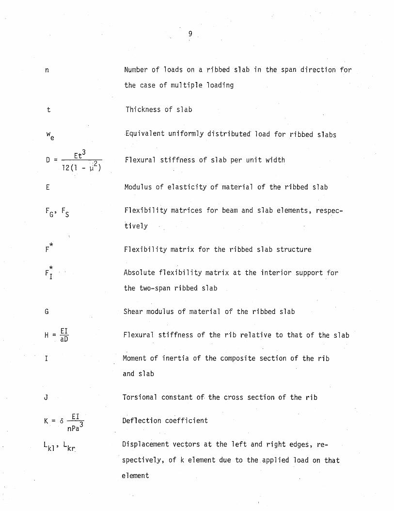
Number of loads on a ribbed slab in the span direction for
the case of multiple loading
Thickness of slab
Equivalent uniformly distributed' load for ribbed slabs
Flexural stiffness of slab per unit width
Modulus of elasticity of material of the ribbed slab
Flexibility matrices for beam and slab elements, respec
tively
Flexibility matrix for the ribbed slab structure
Absolute flexibility matrix at the interior support for
the two-span ribbed slab
Shear modulus of material of the ribbed slab
Flexural stiffness of the rib relative to that of the slab
Moment of inertia of the composite section of the rib
and slab
Torsional constant of the cross section of the rib
Deflection coefficient
Displacement vectors at the left and right edges, re
spectively, of k element due to the applied load on that
element

* L
M
M. J
p
* p
10
Displacement vector of the structure due to the applied
load
Displacement vector at the edge x of i element due to the
applied multiple load on that element
Bending moment of the composite section of the rib and
slab
Maximum bending moment of a simple beam with the same span
length and load spacing as the ribbed slab
torsional moment of the rib
Moment per unit length around the immaginary joint, j, be-
tween the beam and slab elements
In-plane normal forces per unit length on joint j, on
the left and right edges of the element
The applied concentrated load
Internal force vectors at the left and right edges of
k element
Internal force vector of the. ribbed slab structure
Vertical reactions per unit length on joint, j, on the
left and right edges of element
T = GJ E1
v
11
Redundant reactive force vector at the interior support
of the two-span ribbed slab
In-plane shearing forces per unit length on joint, .j,
on the left and right edges of element
Torsiona'l stiffness of the rib relative to its flexural
stiffness
Shear force of the rib
Maximum shear of the beam loaded as for MB
Absolute displacements at the interior support of the
two-span ribbed slab due to the applied load, when the
interior support is ignored
Poisson's ratio of concrete
Absolute value of the maximum deflection of a ribbed slab


2.1 Genera 1
12
CHAPTER 2
METHOD OF ANALYSIS
The analysis of reinforced concrete ribbed slabs subjected to a
single or multiple concentrated load is based' on the method of analysis which
has been used in the studies of the effects of diaphragms in bridges with pre-
stressed concrete I-beam girders by Sithichaikasem and Gamble (11). This
method is possibly even better suited to the monolithic ribbed slab structure
than to the composite bridge structure, since the method was derived assuming
monolithic structures without joints.
In practice, a ribbed slab is usually cast in' plac'e monolithically
with its supports, which are then partially fixed. Hehce, the supporting
conditions deviate somewhat from the restrictions of the method of analjsis,
which is limited to simply supported structures only. This limitation results
from using of Fourier series in the analysis; in which the displacement func
tion, internal forces, and external loads are put in terms of a sine series
which satisfies boundary conditions of a simple support. However, the par
tially restrained supporting condition of the usual ribbed slab structure
would influence the results of the analysis toward the conservative side, so
far as the forces in the ribbed slab are concerned.
2.2 Assumptions
The assumptions in this analysis are concerned mainly with solving
for the'force-displacement relationships of plate and beam elements. Therefore,
13
the basic assumptions for flexure theory of a medium-thick plate, membrane
theory for a thin plate, and theory of biaxial bending combined with axial
force and torsion of a beam will hold for this analysis. Since the ribbed
slab is a reinforced concrete structure, the additional assumptions for
material properties are as follows:
1. Concrete is homogeneous, isotropic~ and elastic;
2. Poisson's ratio for concrete is equal to 0.15.
All supports are assumed to be unyielding.
2.3 One-Span Ribbed Slab
The method of analysis is initiated by decomposing the ribbed slab
into a series of plate and beam elements. At joints between the elements,
there are four unknown internal forces: in-plane normal force N, in-plane
shearing force S, vertical reactive force R, and moment acting perpendicular
to the joint Mj (see Fig. 2.1). Then solutions for the individual plate
and beam elements under the conditions of the applied load and the internal
forces along the joint are carried out separately.
The exact solution of the plate element is rather complicated, since
it is the problem of bending of a plate under the combined action of the lateral
load, edge moments, and forces in the middle plane. For this study, the bend-
ing theory and the plane stress theory for thin plates are applied independentl~
It is not extremely accurate, since bending moments' in the plate are affected
by the in-plane forces. However, this effect is negligible for plates with
small deflections. Another source of error is found in solutions of the mem-
brane theory since equations in the form of Fourier series do not sati'sfy the

14
end support condition ~hat membrane shear should be zero, but the effect is
also negligible, as shown by Sa vern (15).
The flexibility-matrix and displacement vectors at the left and
right-edges of the plate element are obtained by combining solutions of bend
ing and membrane theories. The flexibility matrix and displacement vectors
at the left and right edges of the beam element are determined by integration
of the equilibrium equations of a small element of the beam (see Fig. 2.1),'
and then using the force-displacement relationships for solutions. The de
tailed equations for solutions for both plate and beam elements are discussed
and reported in Ref. 11.
The internal forces can be determined by the compatibility conditions
at the joints of the deco~posed structure. In other words, the decomposed
structure is assembled under the condition that displacements of the plate
and beam elements at the,same joint are equal.
By this argument the solutions can be obtained as follows:
FG is the flexibility matrix of the beam element;
FS is the flexibility matrix of the plate element;
Lkl , Lkr are the displacement vectors at the left and right
edges, respectively, of element k ~ue to the applied
external load on that element;
Pkl , Pkr are the vectors of internal forces at the left and
ri'ght edges of element k
Both the plate and beam flexibility ~atrices have size of 8 by 8, since ,each'

15
element is subjected to eight internal forces (see Fig. 2.1). The flexibil-
ity matrix of each element can be partitioned into four submatrices, as far
as internal f6rces are concerned. For example, for an element k
Fkll 1 Fklr F I f krl: krr
At any joint N, the right edge of the beam element i is connected
to the left edge of the plate element j, or vice-versa. The displacement of
the right edge (i.e., r edge) of the beam element i is:
FGrl P'l + FG P. + L, 1 rr lr lr
and the displacement of the left edge of the plate element + 1 = j is:
For compatibility of joint N, the displacement at the right edge of element
i must equal the displacement at the left edge of element j, and the force
vectors of both elements at the edges of the common joint N must be the same,
tha tis:
and
p, . lr
where PN is the internal force vector at joint N. Then we can write
L'1 - L. J 1 r

16
By applying the above conditions for all the joints, then equations for the.
assembled structure are obtained as follows:
* * * F P = L
where
* F is the assembled flexibility matrix of the structure
* p is the force vector at all joints
* L is the applied load displacement vector
The internal forces at every joint are, therefore, obtained by
solving the above equations. Internal forces in any slab and "beam can be
determined by substituting the joint forces into the equilibrium equations
of the individual element. As far as the geometry of the structure is con-
cerned, it is reasonable that the rib and slab interact somewhat as aT-beam,
but there is no direct way to determine the effective width of the flange of
each rib in this analysis. In order to find the effective T-beam moment, the
T-beam action is evaluated for the condition that the sum of axial forces in
the effective composite T=beam section is zero under pure bending. Then the
composite bending moment of a rib including the interaction with the slabs is
calculated.
2.4 Two-Span Ribbed Slab
Solutions of a two-span ribbed slab are determined by the unit 'load
method, in which there are three steps in the calculations. First, the inte~
rior support is removed, and the structure becomes a simple span ribbed slab
under the applied load. Second, to determine the redundant reactions (vertical

17
reactions and twisting moments), unit loads and. couples are applied to each
rib at the interior support. Third, the solutions of the first and second
steps are combined to yield the solution of the two-span ribbed slab by re-
storing the interior support points to zero deflection and zero rotation about
the rib axes.
Solutibn of the first step is like that ofasimple span ribbed
slab subjected to externally applied load, so the calculation is similar to
that described in Section 2.3. Besides internal forces, solution of this
step also involves absolute displacements (deflections and rotations) at the
interior support. In the second step, the simple span ribbed slab is sub-
jected to unit loads and couples acting on every rib at the interior support
location. Displacements are found using the procedure in Section 2.3, re
sulting in the absolute displacements at the interior support, as well as
internal forces. Then, with the compatibility condition that there are no
vertical displacements or rotation about the rib axis at the interior support
of the structure, equations are formed as follows:
where
* FI is the absolute flexibility matrix of the structure at the
interior support;
RI is the redundant reactive force vector at the interior support;
6 is the absolute displacement vector at the interior support
loc~tion due to the externally applied l~ad, with the interior
support removed.

18
By solving the above equations, the redundant reactions at the interior sup
port line are determined.
Third step, solution of the two-span ribbed slab is obtained by
combining the solution of the first step due to the externally applied load
and that of the second step, using the calculated reactions instead of unit
loads and couples. Then we have:
where
* S = S 1
* S is the solution of a two-span ribbed slab subjected to the
applied load;
Sl is the solution of the first step, considering the applied
load;
S2 is the solution of the second step, considering the applied
unit loads and couples.
This technique of applying redundant reactions instead of the inte
rior support is not exactly correct, since the real support normally supports
not only the ribs but' also the slab. However, the inaccuracy affects only
the portions of slabs close to the support and is negligible for the structure
as a whole.
2.5 Multiple Loads
The analysis of highway bridges (1T,14) was made with single loads
only, and the superposition method was then used for the solution of truck
loadings· or any other combination of "loads. 'For this study, multipl~ loads

19
are considered (i.e., wheel loads of vehicles in parking garages). The super-
position method is not practical, because of the great number of wheel loads
possible in parking garages. Therefore, a direct solution for multiple loads
is necessary.
In the analysis, all vehicles are assumed to have the same wheel
spacings, to weight the same, and have the weight divided evenly among the
four wheels, as is further discussed in Chapter 4. Starting with the method
of analysis described in Sections 2.3 and 2.4, the only things to be changed
for multiple loads are the displacement vectors at the edges of the elements
due to the applied loads. Since the displacement vectors due to single loads
are available, the displacement vectors for multiple loads equal the sum of
displacement vectors at the corresponding edges due to all the externally
applied loads on an element. For example, if there are'M loads on an element
;, the displacement vector at the edge x will be as follows:
where
M I L. N
N=l 1 x
* L: is the displacement vector at the edge x of the element lX
due to M loads
L. N is the displacement vector at the edge x of the element i lX
due to a single load N
Solutions of ribbed slabs due to multiple loads can then be obtained
by the method of analysis in Sections 2.3 and 2.4, with the displacement vec
tors calculated by the above procedure.

20
2.6 Accuracy of the Analysis
The computer program was modified from the program developed by
Sithichaikasem and Gamble (11). The accuracy of the computation depen~s
largely on the number of terms of harmonics used in the calculation for the
Fourier series type equations. It has been shown by Wong and Gamble (14)
that the rate: of convergence toward the ,cor.rect ~olution for a simple-span
bridge is slow after 5 harmonics. At 35 harmonics, 97 percent computational
accuracy was obtained, comparing. total composite moment of all beams with
the static moment as calculated from the elementary beam theory_ The computing
work was carried out on th~ .IBM 360/75 computer, using double precision
arithmetic.
In this study, the computational accuracy of the solution for
shear is also examined, comparing total shear at all supports in all ribs
with the applied load. A simple span ribbed slab with H = 4.5, b/a = 0.052,
and T = 0.100, and a two-span ribbed slab with parameters of the same magni
tudes were taken as examples for showing the computational acturacy of solu
tions. Twenty harmonics were used for the simple span ribbed slab and 35
for the two-spane
The results of two loading cases, a single load P at midspan of
center and edge ribs, are as follows:
Simple-Span Ribbed Slab
Load P at midspan of the center rib:
Total moment at midspan of 17 ribs = 0.2427Pa, 97.1 percent.
convergenc'e
Total shear at supports of 17 ribs = 0.9588P, 95.9 percent
convergence

21
Load P at midspan of the edge rib:
Total moment at midspan of 17 ribs = 0.2443Pa, 97.7 percent
convergence
Total shear at supports of 17 ribs = 0.9652P, 96.5 percent
convergence
Two-Span Ribbed Slab
Load P at midspan of the center rib:
Total moment at midspan plus one-half total moment at interior
support of 17 ribs = 0.2408pa, 96.3 percent convergence
Total shear at all supports of 17 ribs =0.9864P, 98.6 percent
convergence
Load P at midspan of the edge rib:
Total moment at midspan plus one-half total moment at interior
support of 17 ribs = 0.2426Pa, 97.0 percent convergence
Total shear at all supports of 17 ribs = 0.9889P, 98.9 percent
convergence
The static moment is 0.25Pa.
For the simple span ribbed slab, the example above shows that the
computational accuracy for the solution of shear is slightly less than that
of the solution for moment. A reason for this is that some shear forces are
carried directly to the supports by the slab. The composite action between
the ribs and slab is taken directly into account in the solution of moments.
Some of the moment which is unaccounted for after 20 harmonics is resisted by
bending in the slab elements, and most of the rest by the loaded rib.
For the two-span ribbed slab, results' opposite-those of the

22
simple span are obtained. The computational accuracy of solution for: moment
is obtained by comparing total moment at midspan plus one-half of total moment
at the interior support of all ribs (i.e., 17 ribs) with the static moment.
Because of the additional dimension involved in this structure, the moments
at midspan of the unloaded ribs are not all maximum Values. The comparison
to the simple beam moment is' correct only if the total moments in all 17 ribs
are considered. A better result in the computational accuracy for the solu
tion for shear is obtained because only the ribs are supported at the interior
support, where about 70 percent of th~ applied load is carried. Therefore,
the amount of shear carried by the slabs is minimized, and a higher computa-
tional accuracy is obtained.
Metz Reference Room Civil Enginesring Department BlD6 C. E. Buil~ing University of Illinois Urbana, Illinois 61801


23 '
CHAPTER 3
BEHAVIOR OF RIBBED SLABS UNDER A SINGLE CONCENTRATED LOAD
3.1 General
Thi s study has consi dered both one-,span and two-span conti nuous
,ribbed slabs. A single concentrated load is the basic loading case for
studying the general load distributio~ behavior of ribbed ~labs. Various
load locations were chosen to cover the possible range of interest, such as
at midspan of center and edge ribs.
The structural behavior of ribbed slabs subjected to a concentrated
load might be characterized by slab and rib actions. An interpretation of
these actions might be made in two directions, relative to geometry of the
structure. First, in the transverse direction (direction perpendicular t6
the rib), slab action is likely to take the form of an elastic support of
the ribs, especially of the loaded rib. The ribs also act as elastic sup
ports of a continuous one-way slab. Second, in the longitudinal direction
(direction along the rib), the rib is somewhat like a beam on an elastic
f6undation as far as the transverse slab action is concerned. The slab also
acts as a flange of a T-beam which has the rib as its web.
This investigation of the ribbed slab under concentrated loads is
mostly concerned with the study of moment, shear, and torsion (such as their
d'i stri buti ons, as ; nfl uenced by vari ous parameters). The important parameters
in this study are H, b/a, and T, as discussed in Section 1.5. To examine the
influence of these' ~arameters on the load-carrying characteristics of both
simple span and two-span continuous ribbed slabs, various sections were chosen

24
for the analysis. The ribbed slabs analyzed have magnitudes of H varying
from 2.0 to 9.0, b/a from 0.035 to 0.10, and T kept about constant at 0.100
(see Table 3.1). For generality and to help comparisions, the presentations
of moment, shear, and torsion are in dimensionless forms as M/MB3 V/VB
, and
Mt/MB respectively.
3.2 Moment, Shear, and Torsion Diagrams
The study of moment, shear, and torsion diagrams due to single
loads was carried out on both simple span and two-span continuous ribbed
slabs with H = 4.5, b/a = 0.052, and T = 0.100. Two loading cases, for
loads at midspan on the center and edge ribs, will be presented in this sec
tion.
3.2.1 Moment Diagrams
a. One-Span Ribbed Slab
Figure 3.1 shows moment diagrams of a few ribs due to the load at
midspan on the center and edge ribs. The moment diagrams of all ribs, except
the loaded rib and the first adjacent rib, are more or less parabolic curves
which indicates that those ribs were subjected to a distributed load of some
kind. These loads are transmitted from the loaded to the unloaded ribs by
bending and shear forces in the slab. The slab also acts as an elastic support
for the loaded rib," causing a portion of the moment diagram for the loaded
rib between the support and the load to be concave upward. For the load at
midspan on the center" rib, the moment diagra~ of the first adjacent rib is
also concave upward between the support and midspan, indicating greater load

25
distribution occurr~d around midspan (which is close to the applied load).
Instead of being concave, the moment diagram for the first adjacent rib due
to the edge rib ioading is more or less a straight line,_ indicating that
this rib effectively is loaded only near midspan. As a resul·t of the ~se
of the Fourier series, the moment diagrams of the loaded ribs have a rounqed
curve instead of a sharp break at the point of maximum value.
The magnitudes of moments due to the edge rib loading are about
twice those due to the center rib loading. The reason for this is that the
load on the center rib is distributed to adjacent rib on both sides, which
is impossible on the edge rib. For the ribbed slab ~nalyzed in this section,
the maximum moments of the loaded center and edge ribs are O.056Pa and O.125Pa,
respectively, as compared to the simple beam moment of O.25Pa.
b. Two-Span Ribbed ~lab
The moment diagrams of the two-span ribbed slab are presented for
two loading cases--lbads at~midspan on the center and edge ribs of-one span.
Midspan loading location is not for maximum moment, but it is the simplest
location for studying general behavior of the two-span ribbed slab under a
concentrated load and. for making comparisons.
Figure 3.2 shows the moment diagrams of a two-span ribbed slab due
to the above loadings. The general characteristics of these diagrams are
similar to those of the simple span ribbed slab. For this particular ribbed
slab, absolute values of the maximum positive and negative moments of the
loaded edge rib ar~ O.094Pa and O.042Pa respectively, and those of the loaded'
center rib are O.051Pa and O.017Pa. :In. comparison, the maximum positive and·
negative moments of a correspondingly loaded two-span beam are O.203Pa and

26
O.094Pa respectively. It is clear that the maximum moments of the loaded
ribs are significantly smaller than those of the beam, and for the same rea
sons as in the simple span ribbed slabs.
3.2.2 Shear Diagrams
a. One-Span Ribbed Slab
Shear ,diagrams of the unloaded ribs are more or less parabolic
curves between the support and midspan, with maximum values at the supports,
except that of the first adjacent rib which has high shear values on the
portions close to midspan before it curves down to zero there. For the
loaded rib, a distinctive high shear value was obtained on the portion close
to the load, as would be expected. The shear diagram of this particular
ribbed slab shows that shear is as high as O.4P and O.47P in the loaded center
and edge ribs, respectively, whereas simple beam shear is constant at O.5P
all the way to the support. However, shear diagram of the loaded ribs is
not like that of the simple beam, since for the edge rib loading, the maxi
mum shears decrease sharply to a value about the same as those of the un
loaded ribs; for the center rib loading, maximum shears decrease to a value
somewhat less than those of the first few adjacent ribs, indicating good
shear distribution. The maximum positive and negative shears of the loaded
ribs are found a little distance away from midspan, and the portion of shear
diagram connecting these two maximum shears is almost a straight line, which
is a result of using Fourier series.
The shear diagrams also show some idea about how various ribs are
affected when the load is applied at midspan on the center or edge rib. The

27
maximum shear of the loaded rib decreases sharply, indicating that the rib
is subjected to a significant downward load over the portion between the
maximum positive and negative shear points, and to a relatively great up-.- - - --
ward reaction from the slab over the high shear portion. the upward-roaa- ---
decreases rapidly from the point of maximum shear and continues as a small
distributed load to the support, since shear increases slightly from the
support to the high shear portion. Through slab action, the first adjacent
.rib is loaded downward by a load of the same magnitude as the upward load
on the loaded rib (or by one-half of that if the loaded rib is the center
one), although the force is distributed over a greater length than in the
loaded rib. The rib is also subjected to some distributed upward·load with
a more or less p~rabolic shape with the maximum value at mid~pan. Loads on
the other ribs also result from slab action and can be explained in the same
way as above. Examples of these loads are sketched and shown in Fig. 3.3.
b. Two-Span Ribbed Slab
Shear diagrams of the two-span ribbed slab due to the load at mid
span of the first span on the center and edge ribs are. shown in Fig. 3.2.
The general characteristics of the ~iagrams are similar to those of the simple
span, as discussed above. In addition, the decreasing shear at the interior
suppo~t results from the nature of the Fourier series, since the interior
support was replaced by sets of vertical reactions and twisting moments on
the ribs. Sketches sh~wing an interpretation of the shear and torsional mo
ment diagrams near the interior support are shown in Fig. 3.4. For the re
sults of the particular ribbed slab.analyzed in this section, the maximum
positive and negative shears of the loaded center rib are O.39P and O.41P

28
respectively, and those of the loaded edge rib are O.44P and O.50P (whereas
the maximum positive and negative shears of a two-span prismatic beam are
O.41P and O.59P). The difference between the maximum positive and negative
shears of the loaded ribs is much smaller than that of a beam--especially in
the loaded center rib. The effect might be attributed to the transverse
shear distribution that reduces the shear at the support of the loaded rib.
Slab action in the two-span ribbed slab is somewhat the same as that in the
simple span, as far as shear diagrams are concerned.
3.2.3 Torsional Moment Diagrams
a. One-Span Ribbed Slab
Torsion diagrams due to the load at midspan on the center and edge
ribs are shown in Fig. 3.1. This is not the loading case for maximum torsion,
but rather is for maximum bending moment. The location of load for maximum
torsion is somewhere between the support and midspan, as shown by the influence
line for torsion at the support (see Fig. 3.9).
When the loading is at midspan on the center rib, there is no torsion
. on the loaded rib, because of symmetry, and maximum torsion is obtained at the
support of the second adjacent rib. For the first adjacent rib, torsion in
creases slightly from the support toward midspan, until close to the quarter
point of span. There the rate of increase is a little greater and torsion
reaches a maximum value somewhere between the quarter point and midspan,
whereas the other ribs have maximum values at the support. The torsion dia
grams of all ribs except the first adjacent rib are more or less of parabolic
shape between the support and midspan.

29
Load at midspan on,the edge rib results in maximum torsion at the
support of the loaded rib. It is different from the case of the load on the
center rib, sinc~ the edge rib has a free edge, and therefore is freer to
deflect and rotate than the others. The maximum torsion at the support of
the loaded edge ribis more than three times the max,imum torsion caused b,y
the center rib loading. All torsion diagrams for the edge rib loading are
also nearly parabolic for the portion between the support and midspan.
b. Two-Span Ribbed Slab
Figure 3.2 shows the torsion diagrams of the ribs of a two-span
ribbed slab due to a' load at midspan on the center and edge ribs of one span.
At the exterior support,of the loaded span, the maximum torsions of both
loading cases occur in the same manner as those in the simple span ribbed
slab.- At the interior support, the torsion diagrams are also affected by
the Fourier series, as are shear diagrams (see Fig. 3.4 for a graphical in
terpretation). The general characteristics of the torsion diagrams fdr the
two-span ribbed slab are similar to those of the simple span ribbed slab.
3:3 Moment Envelopes and Influence Lines for Moment at Midspan and Influence Lines for Shear and Torsion at Support
The studies of the moment envelopes and influence lines for moment
'at midspan and influence lines for shear and torsion,at support were carried
out for a 'ribbed slab with H = 4.5, b/a = 0.052, and T = 0.100, for both one-
and two-span structur~s~ Two loading cases were considered--one load at mid-
span of the center"and edge ribs. The moment envelopes and influence lines
of any ribbed slab will be similar iri general form. Therefore, the study in

30
this section is intended to show an example of the general configuration
and characteristics for a particular ribbed slab, which could be taken as the
reference;for any ribbed slab.
3.3.1 Moment Envelopes and Influence Lines for Moments at Midspan
a. One-Span Ri bbed Sl ab
Figure 3.5 shows influence lines for moments at midspan of various
ribs due to a lo?d moving on the center and edge ribs. These influence lines
have exactly the same shape and magnitude as the moment diagrams (see Fig.
3.1) due to a load at midspan on the corresponding center and edge ribs.
This phenomena .is explained by the fact that the simple span ribbed slab
obeys the Reciprocal Theorem just as well as a simple beam does. However,
the slab action causes both the shape and magnitude of the influence lines
to be different from those of a simple beam.
Moment envelopes of the loaded ribs and a few adjacent ribs are
also shown in Fig. 3.5. The ~oment envelope for the loaded rib is iimilar
to that of a simple beam, but the magnitude is considerably smaller, as dis
cussed above for the influence lines.
b. Two-Span Ribbed Slab.
For two-span ribbed slabs, the influence lines for moments at midspan
of one span and at the in~erior support due to a load moving on the center
and edge ribs are illustrated in Fig. 3.6. Moment envelopes of the center
and edge ribs and ~ few adjacent ribs are also shown in Fig. 3.6. The general
characteristics of the influence lines and moment envelopes of the loaded ribs

31
are similar to those of a two-span prismatic beam. Furthermore, moment en
velopes of the loaded ribs indicate that the load location for maximum posi
tive moment is approximately 0.4 times the span length from the exterior
support; for maximum negative moment at the interior support, the load- loca
tions for center and edge ribs are about 0.7 and 0.8 times the span length
respectively. These locations for maximum positive and negative moments
compare with 0.43 and 0.57 times span length -in the case of a two-span pris
matic beam. It is quite clear that load location for maximum positive mo
ment of rib and beam are about the same. For maximum negative moment, -the
load location on a rib (espetially a center rib)- is-much closer to the in
terior support than -is true on a beam. The cause of the difference could
be slab action--i~e., load distribution among ribs is better when the load
is far from the suppbrt. Note that better load distribution also means better
momen.t distribution and reduced magnitude of the maximum moment.
For the unloaded rib~, the influence lines for moment at midspan
and moment envelopes are more or less parabolic curves, especially for the
ribs beyond the first adjacent rib (see Fig. 3.6).
3.3.2 Influence Lines for Shear at Support
a. One-Span -Ribbed Slab
Influence lines for shear at the support show the distribution of
reaction shea~s in various ribs due to a load moving on the center and edge
ribs. Figure 3.7 shows:-that shear distribution at the support due to load
at any section on the center rib is better than that due load at the corres
ponding section on the edge rib. Wh~n the load is a certain distance f~om

32
the support, the reaction shear of the loaded center rib is smaller than
those of the first few adjacent ribs (see Fig. 3.7). It could be inter
preted that she~r can distribute transversely to adjacent ribs better than
longitudinally to the support of the loaded center rib. For the edge rib,
shear can distribute transversely only to one side, and it must transmit
the shear longitudinally to the support. These characteristics result from
the geometry of the structure.
Influence lines for shear at the support of the loaded ribs approxi
mate hyperbolic curves. This results from the two dimensional effect rif the
structure (slab action). The difference between the hyperbolic curve and a
straight line is the amount of shear that distributes transversely to adja
cent ribs by slab action. Also, as the load moves closer to the support;
transverse shear distribution is limited and a high reaction shear on the
loaded rib is obtained. For unloaded ~ibs, the influence lines are the re
sult of distributed shears.
Reaction shear is not the maximum shear under a single load, except
for the loaded rib with the load very close to, or at, the support. However,
reaction shear is important, because in case of multipie loading, the maximum
shear is .always the reaction shear.
b. Two-Span Ribbed Slab
Influence lines for shear at the exterior support and at the 0.95
span point (near b~t not at the interior support) due to a load moving on the
center and edge ribs are shown in Fig. 3.8. The general characteristics of
the influence lines for shear at the exterior support are similar to those of

33
the simple span. For shears at 0.95 span, a portion of the influence line
very close to the interior support of the loaded rib is affected by usage
of the Fourier series. In addition, shear distributions among the ribs,
both at the exterior support and at 0.95 span points, due to loads at Vari-
,ous sections on the center and edge ribs are different.from those in the sim
ple span ribbed slab in that shears in the loaded ribs are usually the maxi
mum shears. This could mean that shear distribution in the simple span ribbed
slab is better. From Fig. 3.8, the load location for maximum shear at 0.95
span would be somewhere between 0.90 and 0.95 of the span for both loading
cases. For the unloaded ribs, the characteris~ics of the influence lines
for shear at 0.95 span are also similar to those of the'simple span. There
fore, the affect tif the Fourier series on shear around the interior support
is confined to the loaded ribs only.
3~3.3 Influence Lines for Torsion at Support
a. One-Span Ribbed Slab
Influence lines for torsion at the support of the ribs due to a
load moving on the center and edge ribs are shown in Fig. 3.9. For the ,load
on the edge rib, the greatest maximum torsion is obtained in the loaded rib,
and maximum torsions of the other unloaded ribs are smaller in proportion to
the, distance from the loaded one. The load location for maximum support tor
sionin the loaded rib is nearest to the support, and for unloaded ribs the
location is successively farther from the support, in proportion to the dis
tance from the ,loaded rib.
, When the load moves on the center rib, there is no torsion in the

34
loaded rib because of symmetry, as mentioned in Section 3.2.3, and the great
est maximum torsion is found on the first adjacent rib. In the portion of
the influence line from the support to the load location for maximum torsion
in the first adjacent rib, the rate of increase of torsion is great in the
first adjacent rib; but for the other portion of the span, the rate of de
crease of torsion is also great, resulting in smaller torsion on the first
adjacent rib in this ~ortion of the span (see Fig. 3.9). The characteristics
of load locations on the center rib for maximum torsion in the unloaded ribs
are similar to those of the edge rib loading, as discussed above.
The difference in load locations for maximum torsion at the support
of various ribs result from a shear distribution phenomena--i.e., sheaf dis
tribution is limited if the load is close to the support, as mentioned in
Section 3.3.2. Therefore, for the unloaded ribs far from the loaded one,
the load has to be some distance out on the span before the unloaded rib re
ceives greatest effect of distributed shears causing maximum torsion~
b. Two-Span Ribbed Slab
Influence lines for torsion at the exterior support and at the 0.95
span point due to a load moving on the center and edge ribs are shown in Fig.
3.10. The general characteristics of the influence lines for torsion at both
the exterior support and at 0.95 span are similar to those of the simple span,
as discussed above. But the magnitude of torsion at 0.95 span is somewhat
smaller than at the exterior SUpport. Torsions at the exterior -support of
various ribs are ~ery small when the load is on the other span.
35
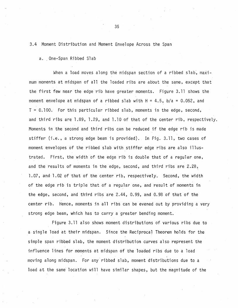
3.4 Moment Distribution and Moment Envelope Across the Span
a. ,One-Span, Ribbed Slab
When a load moves along the midspan section of a ribbed slab~ maji
mum moments at midspan of all the loaded ribs are about the same, except that
the first few near the edge rib have greater moments. Figure 3.11 shows the
moment envelope at midspan of a ribbed slab with H = 4.5, b/a = 0.052, and
T = 0.100. For this particular ribbed slab, moments in the edge, second,
and third ribs are 1.89,1.29, and 1.10 of that of the center rib, respectively.
Moments in the second and third ribs can be reduted 'if the edge rib is made
stiffer (i.e., a strong ~dge beam is provided)., In Fig. 3.11, two cases of
moment 'enve lopes of the ri bbed, slab wi th stiffer edge ri bs are a 1 so ill us
trated. First, the width rif the edge rib is double that of a regular one,
and the results of moments in the edge, second, and third ribs afe 2.28 5
1.07, and 1.02 of that of the center rib, respectively. Second, the width
of the edge rib is triple that of a regular one, and result of moments in
the edge, second, and third ri bs are 2.44, 0.99, and 0.9'8 of that of the
center rib. Hence, moments in all ribs can be evened out by providing a very
strong edge beam, whi~h has to carry a greater bending moment.
Figure 3.11 also shows moment distributions of various ribs due to
a single load at their midspan. Since the Reciprocal Theorem holds for the
simple span ribbed slab, the moment distribution curves also represent the
influence lines for mom~nts at midspan of the loaded ribs due to a load
moving along midsp~n. For any ribbed slab, moment distributions due toa
load at the sam~ location will have similar shapes, but the ~agnitude of the

36
distributed moments depends upon the important parameters discussed in Sec
tion 1.5. Therefore, the study in this section should be considered as a
reference for a general ribbed slab. The affects of those parameters on
moments will be discussed later.
b. Two-Span Ribbed Slab
Figure 3.12 shows moment envelopes and moment distributions at mid
span of the first span of a two-span ribbed slab due to a load moving along
the midspan, and also those of the coresponding negative moment at the interior
support. The general behavior of moment envelope and moment distributions at
midspan is similar to the simple span ribbed slab; for example, moments under
the load at midspan of the edge, second, and third ribs are 1.84, 1.24, 'and
1.08 of that of the center rib, respectively. The mom~nt envelope at the
interior support due to the load at midspan is similar to those of the posi
tive moment at the midspan. But the negative moments of the edge and second
ribs, as compared t6 that of the center rib, are much greater than i~ the case
of the positive moments. The results in Fig. 3.12 indicate that negative
moments at the interior support of the edge, second, and third rib are 2.47,
1.53, and 1.06 of that of the center rib, respectively. Negative moment dis
tributions of various ribs at the interior support due to midspan loads are
also shown in Fig. 3.12. The distributed negative moment in the first ad
jacent rib relative to that of the loaded rib is considerably greater than
the relative distributed positive moment of the same rib at midspan. Other
characteristics of negative moment distributions in general are similar to
those of the positive moments at midspan.

37 .
. .. . .
The affects of a stiffened edge rib or edge beam are not presented
for the two-span' ribbed slab. However, results similar to those of the simple
span ribbed slab should be expected.
3.5 Effects .of Torsional Stiffness on Moment, Shear, and Torsion
The affects of the parameter T on moment have been studied and re
ported tn Ref. 5 arid 11. Reference 11 show~d that the moment of the loaded
girder decreases as magnitude of T increases, but a significant affect was
found ohly in the range of T fro~ 0.0 to 0.20. In Ref. 5, test results from
steel I-beam girder-slab bridges indicated that the affect of variation in
torsional stiffness of steel I-beam is negligible.
For this study, the influence of the parameter T on moment, shear,
and torsion are presented. Theinvestigati·on was performed 'on simple sp~a~ ribbed
slabs with constant magnitudes ,of H = 2.0 and 4.0, b/a = 0.05 and 0.10, and
with T varied from 0.063 to 0.161 (see Table 3.2). This is in the ~ange of
significant affects of T on moment as reported in Ref. 11. The study 'con~
sidered two loading cases (load at midspan on the center and edge ribs), and
results of the analysis are shown in .Fig. 3.13. The influence of T on the
moments at midspan, a~d shear at the support of the loaded ribs are similar-
moment and shear.decrease as T increases. But the changes are not very sig
nificant in the range of T investigated, which is considered the practical
range for conventional ribbed slabs. For example, the. results for ribbed
slabs w;'th H = 4 .. 0 and b/a = 0.05 show that the maximum moments of the center
and edge ribs decreased 8.5 and 13.7 percent, respectively, as T increased'
98.8 percent.

38 :
The influence of T on ~maximum torsional moment at the support due
to the above loadings is opposite the affects on moment and sheara As r'
increases, the maximum torsion also increases quite sJgnificantly. The re
sults of the same ribbed slabs with H = 400, bla = 0.05 show that the mix
mum torsion due to a load at midspan on the center and edge ribs increased
59.6 and 42.8 percent, respectively, as Tincreased 98.8 percent (see Fig.
3.13). However, in this study, the magnitudes' of T used are approximately
constant, because the influence of T on bending moment and shearare'very
small,· as mentioned above. The influence of T.on the torsion is significant,
but the incr.eased torsional strength accompanying increased torsional stiff
ness would be enough to comp~nsate for the amount of the increased torsion.
Furthermore, torsion is considered of secondary importance in the structure.
In addition, the magnitude of T selected for this analysis (about 0.100) are
considered common for general practice.
3.6 Effects of Hand bla on Moment, Shear, and Torsion
From the results of the studies of behavior of ribbed slabs under
a concentrated load in previous sections, it might be concluded that the
characteristics of moment" shear!! and torsion distributions are somewhat
changed according' to different load locations on different ribs. In order
to make the study in this section simple and yet reveal enough 'detail, solu
tions for two· loading cases are ·considered--l oad at midspan on the center
and edge ribs. These load locations give the lower and upper bound values of
moment for any ribbed'slab under a concentrated 10ad~ For shear and torsibn,
the center and edge ribs might be considered as being representative of the

39
interior and exterior ribs. And as shown in Sections 3.3.2 and 3.3.3, the
characteristics of the shear and torsion distributions also depend upon
locations along the ~pan; therefore, midspan is considered to be a suitable
load location for studying the general behavior.
The study of the influence of·H and bla on' moment distribution is
confined to the midspan section, where maximum moments are obtained. Shear
and torsion are studied at the support. The results 6f th~ ribbed slabs
analyzed with parameters of various magnitudes, as shown in Table 3.1, ~re
presented in this section.
3.6.1 Effects of H andbla on Moment Distribution Across Span and Maximum Moment of the Loaded Rib
a. One-Span Ribbed Slab
The moment distributions among ribs of simple span ribbed slabs due
to a load at mirlspa~ on the center and edge ribs depend upon the values of
the parameters Hand b/a. The results of the analysis show that the moment
distribution is better for the ribbed slab with smaller ~.and bjavaloes, as
shown in Fig. 3.14. Comparing graphs of constant bla and various H values,
and those of constant H and various bla ratios, it is evident that the effect
of bla is somewhat greater than that of H. For a ribbed slab, the moment dis~
tribution due to the load on the center rib is better than that due ·to the
load on the edgerih. Examples of two simple span ribbed slabs with H = 2.0,
bla = 0.035, and H = 9.9, bla = 0.10 are as follows:.
H = 2.0, bla = 0.035
Load at midspan on the edge rib:

40
Maximum moment of the loaded rib = 0.0761Pa = 0.3044MB Moment of the eighth adjacent rib (center rib) = 0.0041Pa = 0.0164MB
Load at midspan on the center rib:
Maximum moment of the loaded rib = 0.0366Pa = 0.1464MB Moment of the eighth adjacent rib (edge rib) = 0.0043pa = 0.0172MB
H = 9.0, b/a = 0.10
Load at midspan on the edge rib:
Maximum moment of the loaded rib = 0.1507Pa = 0.6028MB Moment of the third adjacent rib (rib no. 4) = 0.0066Pa = 0.0264MB
Load at midspan on the center rib:
Maximum moment of the loaded rib = 0.0940Pa = 0.3760MB Moment of the third adjacent rib (rib no. 6) = 0.0073Pa = 0.0292MB
From the above examples we can see that for the ribbed slab with H = 2.0,
b/a = 0.035, the moment of the eight rib from the loaded edge rib (i.e., the
center rib) is about 5.4 percent of that of the loaded rib, and the moment of
the eighth rib from the loaded center rib (i.e., the edge rib) is about 11.8
percent of that of the loaded rib. For the ribbed slab with H = 9.0, b/a = 0.10,
the moment of the third adjacent rib from the loaded edge rib (i.e., rib no. 4)
reduced to about 4.4 percent of that of the loaded rib, and the moment of the
third rib from the loaded center rib (i.e., rib no. 6) reduced to about 7.8
percent of that nf the loaded rib. It is quite obvious that the moment dis
tribution of the former ribbed slab is much better than that of the latter one,
and the maximum moments of the corresponding loaded ribs of the second ribbed
slab are much greater.

41
As a result of good moment distribution, maximum moment of the loaded
rib is smaller than if moment distribution is not good. It may be concluded
that the magnitude of the maximum moment of the loaded rib is a 'direct func
tion of Hand bla, which control the moment distributions amring ribs. The
relationships of the maximum moments of the loaded ribs with Hand bla are
shown in Fig. 3.23. As shown in Fig. 3.23, the effects of Hand bla on the
maximum moment are not in the same order. Graphs of the maximum moment versus
bla, for several constant H values, are closer together and have steeper
slopes than graphs of the maximum moment versus H. Therefore, it is evident
that bla has a greater effect on the maximum moment of the loaded ribs than
H., Furthermore, as a smaller maximum moment of the loaded rib alsQ means
better moment distribution and vice versa, it is evident that bla is a more
important parameter in controlling moment distribution than H.
b. Two-Span Ribbed Slab
The study of moment distributions among ribs of two-span ribbed
slabs concentrated at the sections at midspan of the first span and at the
interior support. Positive and negative moment distributions due to a load
at midspan of one span on the center and edge ribs are illustrated in Fig.
3.15 and 3.16. The results show that the general characteristics of moment
distributions at midspan are similar to those of the simple span. For nega
tive moment at the interior support, moment distribution characteristics are
similar to those of ,the-positive moment when load is on the edge rib. For'a
load on the center-rib, the negative moment in the first adjacent rib is
comparabJe to that of the loaded rib; as discussed in Section 3.4. The

42
effects of Hand b/a on moment distributions, both at midspan and the interior
support, are similar to those noticed in the simple span ribbed slab--i.e., a
better moment distribution is obtained in a ribbed slab with smaller Hand
b/a values.
Relationships of the maximum positive and negative moments of the
loaded ribs versus Hand b/a are also similar to those of the maximum moment
of the simple span--i.e., maximum moment of the loaded ribs increases at a
diminishing rate as Hand b/a increase (see Fig," 3.24).
3.6.2 Effects of Hand b/a on Shear Distribution Across Span and Maximum Support Shear
a. One-Span Ribbed Slab
Shear distributions at the support due to a load at midspan on the
center and edge ribs of various ribbed slabs are illustrated in Fig. 3.17.
The distribution diagrams show that maximum support shear did not occur in the
loaded rib except in the case of a loaded edge rib with rather stiff ribs and
larger b/a ratios. For the center rib loading, the maximum shear can be in
any of the first few adjacent ribs, depending upon Hand bfa, but never in
the center rib. If- it is an edge rib loading, the maximum shear is either
in the loaded or first adjacent rib. The effects of Hand b/a on shear dis-
tributions are similar to those on moment distribution--i.e., the smaller H
and b/a values result in better shear distribution.
In this analysis, the smallest Hand b/a are 2.0 and 0.035, and
the greatest are 9.0 and 0.10, respectively. Comparisons of shear distributions
at support due to a load at midspan on the center and ribs of these two

43
ribbed slabs are as follows:
H = 2.0, b/a = 0~035
Load at midspan on the edge rib:
Shear of the loaded rib = O.0703P = O,.1406VS Maximum shear in the first adjacent rib (rib no. 2) = 0.0820P =, 0.1640Vs Shear of the eighth adjacent rib (center rib) = 0.0129P = 0.0258V
~ S
Load at midspan on the center rib:
Shear of the loaded rib = 0.0166P= 0.0332Vs . Maximum shear in the third adjacent rib (rib no. 6) = 0.0369P = 0.0738VS Shear of the' eighth adjacent rib (edge rib)
H = 9.0, b/a = 0.10
Load at midspan on the edge rib:
Shear of the loaded rib (maximum shear)
Shear of the fourth adjacent rib (rib no. 5)
Load at midspan on the center rib:
Shear of the loaded rib
= 0.0130P = 0.0260Vs
= 0.2200P = D.4400Vs = 0.0017P= 0.0034VB
= 0.0750P = 0.1500Vs Maximum shear in the first adjacent rib (rib no. 8) = 0.1097P =0.2194VB Shear of th~ fourth adjacent rib (rib no. 5) = 0.0050P = O.OlOOVs
Shear distributions in the above example are quite different; the former rib
bed slab with load at midspan on the edge rib, shear in the eighth adjacent
rib (i.e., center rib) is about 15.7 percent of the maximum shear, and with
load at midspan 'on·the center rib, shear in, the eighth adjacent rib (edge
rib) is as high as 35.2 percent of the maximum shear. In the second ribbed

44 .
slab with a load at midspan on the edge rib, shear in the fourth adjacent
rib (i.e., rib no 5) is reduced to about 0.8 percent of the maximum shear,
and with load at midspan on the center rib, shear in the fourth adjacent
rib (i.e., rib no 5) reduced to about 4.6 percent of th~ maximum shear." It
is clear that shear distributions of the former ribbed slab are much better
than that of the latter one.
The relationships of the maximum shear with changes in Hand b/a are
shown in Fig. 3.25. The graphs indicate that the maximum support shear due to
a load at midspan on the center and edge ribs increases more or less linearly
as b/a increases. The effect of H on the maximum shear is somewhat similar
to that of bfa, but is less significant.
b. Two-Span Ribbed Slab
Shear distributions at the exterior support and at the 0.95 span lo
cation due to a load at one midspan on the center and edge ribs are shown in
Fig. 3.18 and 3.19, respectively. Note that according to the sign convention
'used in this analysis (see Fig. 2.1), shears at 0.95 span are negative, but
for convenience, the absolute values are used in Fig. 3.19~ The character
istics of shear distributions, at both the exterior support and the 0.95
span position, a~e somewhat different from those of the simple span ribbed
slabs, in that the loaded ribs for both loading cases carry the maximum sup
port shears for nearly all values of the parameters Hand b/a. The maximum
shears near the interior support are generally about twice the shear forces
at the exterior supports for the midspan loading cases considered.
The effects of Hand b/a on the characteristics of the shear

45
distributions are similar to those in the simple span ribbed slabs, i.e.,
smaller Hand b/a values result in better shear distribution. The relation-
ships of the maximum reaction shear with Hand bfa, as can be seen in Fig. 3.26,
are also similar to those in the simple span ribbed slabs, i.e., the maximum
reaction shear increases as Hand b/a increase.
3.6.3 Effects of Hand b/a on Torsional ,Moment distribution, and Maximum Torsion
a. One-Span Ribbed Slab
Torsional moment di~tributions at the support due to the same
loadings used in the'studies of moment and shear distributions are,considered
in this section. 'These loadings are not for maximum torsion, but they are
simply for general study and comparison. The torsion distributions of se
lected ribbed slabs with various values of Hand b/a are shown in Fig. 3.20.
Note that the torsions due to the load at midspan on the edge rib are negative
according to the sign convention, but the, absolute values are used in fig.
3.20. The effects of Hand b/a on torsion distributions are such that the
distribution is better for the smaller H and- b/a. Maximum torsion due to
the load on the edge rib is much greater than that due to the load on the
center rib, because of the geometry of the structure.
The relationships of maximum torsions for both loadings as, functions
of Hand b/a are shown in Fig. 3.27. The maximum torsion increases at a dimin
ishing rate as H and ~/a increase, in a manner similar to that described in
Section 3.6.1, but the effect of H on the maximum torsional moment is some-
what greater than that on the maximum bending moment.
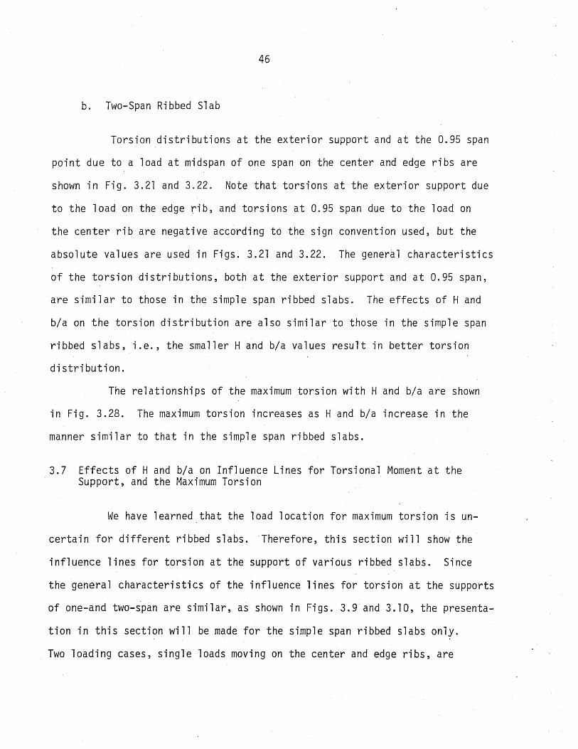
46
b. Two-Span Ribbed Slab
Torsion distributions at the exterior support and at the 0.95 span
point due to a load at midspan of one span on the center and edge ribs are
shown in Fig. 3.21 and 3.22. Note that torsions at the exterior support due
to the load on the edge fib, and torsions at 0.95 span due to the load on
the center rib are negative according t6the sign convention used, but the
absolute values are used in Figs. 3.21 and 3.22. The general characteristics
of the torsion distributions, both at the exterior support and at 0.95 span,
are similar to those in the simple span ribbed slabs. The effects of Hand
bja on the torsion distribution are also similar to those in the simple span
ribbed slabs, i.e., the smaller Hand bja values result in better torsion
distribution.
The relationships of the maximum torsion with Hand bja are shown
in Fig. 3.28. The maximum torsion increases as Hand bja increase in the
manner similar to that in the simple span ribbed slabs.
3.7 Effects of Hand bja on Influence Lines for Torsional Moment at the Support, and the Maximum Torsion
We have learned that the load location for maximum torsion is un-
certain for different ribbed slabs. Therefore, this section will show the
influence lines for torsion at the support of various ribbed slabs. Since
the general characteristics of the influence lines for torsion at the supports
of one-and twa-span are similar, as shown in Figs. 3.9 and 3.10, the presenta
tion in this section will be made for the simple span ribbed slabs only.
Two loading cases, single loads moving on the center and edge ribs, are
47
considered. The influence lines of the ribs with the maximum torsion for
each loading case will be compared for various values of Hand bfa, i.e.,
the influence lines of the loaded edge rib, and the first adjacent rib (rib
no. 8) due to the load on the center rib.
Figure 3.29 shows the influence lines of the ribs mentioned above
for various ribbed slabs analyzed.. The load locations for the maximum tor
sion at the support for each ribbed slab are a little different, for the
two loading cases. This location is nearer to the support for the smaller
Hand b/a values. For the case of loading on the edge rib, load locations
for the maximum torsion at th~ support of the ribbed slabs analyzed are be
tween 0.15 and 0.35 span from the support; and for the case of loading on the
center rib, these-locations are in the range of 0.1 to 0.3 of the span. The
maximum torsion due to the former loading is much greater than that due to
the later loading.
The relationships of the maximum torsion with Hand b/a are shown
in Fig. 3.30, and they are similar to those due to a load at midspan on the
center and edge ribs, as.described in Section 3.6.3.

48
CHAPTER 4
RIBBEQ SLABS ,UNDER MULTIPLE LOADS
4.1 General
The study of the general characteristics of ribbed slabs subjected
to multiple loads, especially in parking garage floors, is the purpose of
this chapter, and both one- and two-span structures are investigated. Multi
ple loads are considered to be the wheel loads of several parked cars of
equal weight, and each car having the weight divided evenly among the four
wheels. The arrangements of the loads will be made in such way that worst
conditions are obtained, even though cars might not be parked like that in
general paractice. In fact, cars are movabl~ loads, which might cause_im
pact and repeated load effects. However, in this study, static load is con
sidered most important, because car speed in a parking garage is very slow
and not all cars move or brake at the same time.
In this study, it is assumed that the cars are parked perpendicular
to the ribs, so that the maximum bending moment, shear, and torsional moment
in the ribs are obtained. The length of wheel base and spread between wheels
(or tread width) are 'taken as ten and five feet, respectively. These dimen
sions are based on the information by Burrage and Morgen (16), and Baker (17).
The car spacing is based on a suggested minimum width of the stall in a parking
garage of eight feet. Distance between rows of cars from wheel base to wheel
base is taken as six feet (i.e., the cars are parked bumper-to-bumper).
The characteristics of ribbed slabs under multiple loads will be
studied ,under two situations; first, the perimeter wheel loads are on the
edge rib and second, the perimeter wheel loads are on the second rib. The

49
system of loading considered in this chapter is shown in Fig. 4.1. The cross
sections and span lengths of the ribbed slabs in Table 3.1 will be used for
the analysis. The presentation of results will be in dimensionless forms in
order to make the study more general, since some of the ribbed.slabs analyzed
have different span lengths and were subjected to different numbers of loads.
The dimensionless quantities are M/MS' V/VS' and Mt/MS' where M, V, and Mt are bending moment, shear, and torsional moment of a rib, respectively, and
MS and'VS are the maximum moment and shear of a simple span beam which has
the same span length and is subjected to loads with the spacing as the ribbed
slab. Values of various MB and Vs .are listed in Table 4.1 for ease of compar
ison with the results of ribbed slabs discussed in this chapter.
4.2 Moment, Shear, and Torsional Moment Diagrams
The studies of moment, shear, and torsional moment diagrams of the
ribs of one- and two-span ribbed slabs are carried out on a ribbed slab which
has parameters H = 4.5, b/a = 0.052, and T = 0.100. Loadings for maximum mo
ment, shear, and torsion are considered, in which the loadings for maximum mo
ment and shear are coincident. For two-span structure, loadings for maximum
positive and negative moments also produce maximum shears at the exterior and
interior supports, resp~ctively.
The moment, shear, and torsional moment diagrams, for both one- and
two-span ribbed slabs, due to loadings mentioned above, are illustrated in
Fig. 4~2 and 4.3. The general configurations of the moment diagrams are similar
to those of isolated beams subjected to a uniformly distributed load. This
phenomena might be explained that the loaded ribs or slabs were subjected to

50
groups of concentrated loads with rather closed spacings (i.e., three and five
feet alternately). Furthermore, these concentrated loads were replaced by a
Fourier series approximation, which tends to distribute the loads at the load
locations. The slab ~lso tends to spread out the loads as they are distributed
from rib to rib. Therefore, the influence of a group of concentrated loads be
comes similar to that of a distributed line load.
Shear diagrams for the ribs subjected directly to the loads have
some sharp slope discontinuities in the diagrams.at the load locations because
of the concentrated load effects. For the ribs which are not directly under
the loads the shear diagrams are more or less parabolic curves. Fo~· two-span
structure, a small portion of the shear diagram near the interior support is
affected by using Fourier series approximation; the maximum shear is found at
a very short distance from the interior support (i.e., at the 0.95 span point)
instead of the support.
Torsional moment diagrams for one- and two-span ribbed slabs are
also shown in Figs. 4.2 ·and 4.3, respectively. The general ch~racteristics
of these diagrams are similar to those of shear diagrams. for the ribs which
are not directly under the applied loads, as mentioned above. Torsional mo
ment diagrams for the two-span ribbed slabs due t6 loads on one span (i.e.,
loadings for maximum positive moment) or two-span symmetry (i.e., loading for
maximum negative moment at the interior support) are also affected by use of
the Fourier series at the interior support. But for two span asymmetric load
ing (i.e., loading for maximum torsional moment at the interior support of the
center rib), the torsional moment diagram is unique as shown in Fig. 4.3. Be~
cau~e torques are applied to the rib in the opposite di~ection at the interior
support by such a loading, the effect of using Fourier series is eliminated.

51
4.3 Multiple Loads for Maximum Moment and Shear
The study of moments of ribbed slabs subjected to multiple loads
is focused on the maximum moments of the ribs, and the distributions of mo
ments. The characteristics of moment distributions among ribs depend upon
the properties of the ribbed slabs and the loading conditions. In this study,
the results of the analysis for the ribbed slabs listed in Table 3.1 are con-
sidered to cover the normal range of the important parameters for ribbed
slabs. The loadings are again arranged such that the perimeter loads are
Note that the load patterns for maximum positive and negative moments are
coincident with those for maximum ~hears for dne- and two-span ribbed slabs,
respectively.
4.3.1 One-Span Ribbed Slab
For the one-span ribbed slab, bending moment is important at mid
span, whereas the combination of shear and torsional moment are most impor
tant at the, support. Loading for maximum moment ~lso results in maximum shear,
but torsional moment is small. However, the effect of torsional moment in
combination with shear should be considered. Therefore, moment at midspan,
and shear and torsional moment at the support due to the loadings for maximum
moment are presented.
a. Moments at Midspan
Maximum moments at midspan of various ribs due to both loading cases
are shown in Fig. 4.4 for comparison. For the loading -with the perimeter
52
loads on the edge rib, the maximum moment always occurred on the edge rib, and
its magnitude was considerably greater than the moments in the other ribs.
For the loading with the perimeter loads on the second rib, the maximum moment
might be in the edge or an interior rib, depending upon properties of the
ribbed slab, in which b/a has the major effect (i.e., the maximum moment is
in an interior rib for all ·the ribbed slabs analyzed with bja greater than
0.035). The maximum moment due to this loading is considerably smaller than
that of the former loading. The results in Fig. 4.4 show that moment distri
butions are quite uniform, especially for ribbed slabs with small Hand b/a
values, subjected to loads of the latter case.
b. Shear and Torsional Moment at the Support
For a flexure member, maximum shear is usually another force to be
considered; shear is as important as bending moment, especially for a member
without web reinforcement. For ribbed slabs s~bjected to concentrated loads,
not only shear but also .torsion exists at the support, as mentioned above.
As far as the combined shears and torsions are concerned, the most significant
torsion due to these loadings is not the maximum totsion, but the torsion in
the rib with the maximum shear. However, torsion'in various ribs is shown for
better understanding. Shear and torsion at the support due to both loading
cases for maximum moment are shown in Figs. 4.5 and 4.6, respectively. The
shear distributions are less uniform than moment distributions for both loading
cases. The toriion distributions are different and difficult to compare with
moment or shear distributions, because the sign for torsion depends upon the
direction of rotation of the ribs about their longitudinal axes. Therefore,.

53
torsion in the ribs on the opposite sides of a load would have a tendency to
have different signs.
The general characteristics of the effects of loading conditions,
H, and b/a on both shear and torsion are similar to those on moments. "For
the loading with the perimeter loads on the edge rib, both maximum shear and
torsion oc~urred in the edge rib. For the loading with the perimeter loads
on the second rib, the torsion corresponding to the maximum "shear is very
small.
For example, maximum moment, shear and the corresponding torsion
of two ribbed slabs with H = 2.0, b/a = 0.035, and" H = 9.0, b/a = 0.10 are
shown as follows:
H = 2.0, b/a = 0.035
Perimeter loads on the edge rib:
Maximum moment (in edge rib)
Maximum shear (in edge. rib)
Corresponding torsion (in edge rib)
Perimeter loads on the second rib:
Maximum moment (in edge rib)
Maximum shear (in second rib)
= =
0.3185MB 0.4000VB
= -0.0226MB
= =
0.2579MB 0.3016VB
Corresponding torsion (in second rib) = -0.0052MB
H = 9.0; bja =0.10
Perimeter loads on the edge rib:
Maximum moment (in edge rib)
Maximum shear (in edge rib)
=
=
0.5685MB 0.5737VB

54
Corresponding torsion (in edge rib) = -0.0567MB
Perimeter loads on the second rib:
Maximum moment (in rib no. 6) = 0.4255MB Maximum shear (in rib no. 7) = 0.4l58VB Corresponding torsion (in rib no. 7) = 0.0031MB
These are the results of the smallest and greatest maximum moments for each
loading case among the ribbed slabs analyzed.
4.3.2 Two-Span Ribbed Slab
In the positive moment region only the bending moment is important,
whereas at the exterior support the combination of shear and torsion are im
portant. In the negative moment region, or at the interior support, bending
moment, shear, and torsion can exist simultaneously in many combinations,
depending on both the loading and the properties of the structure. Themost
important combinations could be considered as follows: First, the case of
maximum moment plus maximum shear, and torsion, and second, the case of maxi
mum torsion plus shear and moment. The first case will be discussed in this
section, ahd the second case will be discussedlat~r.
a. Moment at 0.44 Span and at the Interior Support
For a two-span ribbed slab, the maximum positive mDment due to the
applied load does not occur at midspan, but rather at a point close to midspan,
as shown by the moment diagrams in Fig. 4.3. For this study, the moment at
0.44 of the span from the exterior support is considered to be the maximum
positive· moment. If the maximum moment occurs at any other section, the

55
value of moment obtained at 0.44 span would close enough to the maximum moment
for any practical purpose, because the moment diagrams show that the rate of
change of moment is very small in that portion of the span (see Fig. 4.3),
The positive moment distribution at 0.44 span and the negative mo
ment distributinn at the interiot support of various two-span ribbed slabs
due to the loading cases for maximum positive and negative moments are shown
in Figs 4.7 and 4.8, respectively. The general characteristics of the solu
tions for the positive moment are similar to those of the moment at midspan
of the one~span ribbed slabs, as discussed previously. The effetts of Hand
b/a on the negative moment at the interior support are similar to those on
the positive moment at 0.44 span or the moment at midspan of the one-span
ribbed slabs, in that a better moment distribution is obtained for the smaller
Hand b/a values. But the negative moment distributions at the interior sup
port are a little less uniform than those of the positive moments. One reason
for this might be that the negative moment is most affected by loads which
are relatively close to the interior support, whereas the positive moment is
affected by most of the loads in the span, as shown ~y the influence line for
positive and negative moments at midspan and the interior support, respectively
(see Fig. 3.6). Note that the'distribution of loads near midspan is better
than that of loads near the support .
. The magnitudes of the maximum negative moments are greater than
those, of the maximum positive moments, and for a similar loading case, the
maximum positive and negative moments usually occurred in the same rib. In
addition, the negative moments at the interior support due to loadings for
maximum positive moment are exactly one-half the maximum negative moments
shown in Fig. 4.8.

56
b. Shear and Torsional Moment at the Exterior Support and at 0.95 Span
Shear and torsion distributions at the exterior support and at the
0.95 span position due to two loading cases for both maximum positive and nega
tive moments are shown in Figs. 4.9 to 4.14. The values at the 0.95 span point
are presented instead of at the interior support, because of the effects of
Fourier series, as mentioned before. The general characteristics of the shear
and torsion distributions, as shown in the figures mentioned above, are simi
lar to those of the one-span ribb~d slabs. For the loadings with the perimeter
loads on the second rib, torsion is relatively small as compared to that due
to the loading with the perimeter loadsbn the edge rib. The important tor
sions due to these loadjngs are those of the ribs with maximum shear at the
exterior support, and with maximum shear and moment at the interior suppo~t.
The shear and torsion distributions at the exterior support due to
loadings for maximum negative moment are similar to those due to loadings for
maximum positive moment, except that the magnitudes are smaller. They are
also very similar to the values for one-span structures discussed previously.
Therefore, such shear and torsion distributions at the exterior support are
not presented. At the.0.95 span location (or at ~he interior support for
moment), the combination of negative moment, shear, and torsion, makes the
problem more complicated than at the other end of the span. Shears at the
0.95 span point due to both loadings for maximum negative moment are consider
ably greater than those due to loadings for maximum positive moment. Negative
moment at the interior support due to the loadings for maximum negative mo
ment is twice that due to the loadings for maximum positive moment. The
combined shear, torsion, and bending moment at the interior support due to
57
loadings for maximum negative moment is the most important set of forces
governing the design of ribbed slab structures.
For example, solutions of two ribbed slabs with H = 2.0, b/a = 0.035,
and H = 9.0, b/a = 0.10, are shown as follows:
H = 2.0, b/a = 0.035
Loadings for maximum positive moment at 0.44 span
Perimeter loads on the edge rib:
Maximum positive moment (in edge rib)
Maximum shear at the exterior support (in edge rib)
Torsion at the exterior support (in edge rib)
Maximum shear at 0.95 span (in edge rib)
Torsion at 0.95" span (in edge rib)
N~gative moment at the interior support (in edge ri~)
Perimeter loads on the second rib:
Maximum positive moment at 0.44 span (in edge rib)
Maximum shear at the exterior support (in rib no. 2)
Torsion at the exterior support (in rib no. 2)
Maximum shear at 0.95 span (in ri~ no. 2)
Torsion at 0.95 span (in rib no. 2)
= 0.2563MB = 0.36llVB = -0.0205MB = -0.4718VB = 0.0158MB = -O.1873MB
= 0.1992MB = 0.2667VB = -0.0046MB = -0.3099VB = 0.0034MB
Negative moment at the interior support (in rib no. 2) = -0.1266MB
Loadings for maximum negative moment at the interior support
Perimeter loads on the edge rib:
Maximum negative:moment (in edge rib)
Maximum shear at 0.95 span (in edge rib)
= -0.3746MB = -0.6390VB

58
Torsion at 0.95 span (in edge rib)
Maximum shear at the exterior support (in edge rib)
Torsion at the exterior support (in edge rib)
Perimeter loads on the second rib:
Maximum negative moment (in rib no. 2)
Maximum shear at 0.95 span (in rib no. 2)
Torsion at 0.95 span (in rib no. 2)
Maximum shear at the exterior support (in rib no. 2)
Torsion at the exterior support (in rib no. 2)
H = 9.0, b/a = 0.10
Loadings for maximum positive moment at 0.44 span
Perimeter loads on the edge rib:
Maximum positive moment (in edge rib)
Maximum shear at the exterior support (in edge rib)
Torsion at the exterior support (in edge rib)
Maximum shear at 0.95 span (in edge rib)
Torsion at 0.95 span (in edge rib)
Negative moment at the interior support (in edge rib)
'Perimeter loads on. the second ri b:
0.01Q2MB 0.3314VB
= -0.0185MB
=
=
= -0.2531MB = _n L1.nnl\l
V •• VVI 'B
= 0.0018MB = O.2394VB = -0.0040MB
= 0.4579MB
= 0.5317VB = -0.0521MB = -0.6502VB = 0.0423MB = -0.3158MB
Maximum positive moment (in rib no. 6) = O.3353MB Maximum shear at the exterior support (in rib no. 7)' = 0.3809VB Torsion at the exterior support (in rib no. 7) = O.0042MB,
Maximum shear at 0.95 span (in rib no. 7)
,Torsion at 0.95 span (in rib no. 7)
= -O.4608VB = -0.0027MB
Negative moment at the interior support (in rib no. 7) = -0.2234MB

59
Loadings for maximum negative moment at the interior support
Perimeter loads on the edge rib:
Maximum negative moment (in edge rib)
Maximum shear at 0.95 span (in edge rib)
To~sion at 0.95 span (in edge rib)
Maximum shear at the exterior support (in edge rib)
Torsion at the exterior support (in edge rib)
Perimeter loads on the second rib:
Maximum negative moment (in rib no. 7)
Maximum shear at 0.95 span (in rib no. 7)
Torsion at 0.95 span (in rib no. 7)
Maximum shear at the exterior support (in rib no. 7)
Torsion at the exterior support (in rib no. 7)
4.3.3 Maximum Deflections
=
=
=
=
=
=
=
=
=
=
-0.'6316MB -0.8673V
B
0.0290MB 0.4880VB
-0.0475MB
-0.4468MB -0.5994VB -0.0068MB
0.3449VB 0.0053MB
The maximum deflections df ribbed slabs, both one- and two-span sub
jected to multiple loads, resulted from loading for maximum positive moment.
The absolute values of maximum deflection (i.e., in inches) of the ribbed
slabs analyzed are shown in Tables 4.2 and 4.3.' Since the ribbed slabs ana~
lyzed have different span lengths and cross section properties, the deflection
coeffi ci ents in terms of the app 1 i ed load, span 1 ength, and the .fl exura 1
stiffness of the composite section are considered for ,the study of the gener
al relationships involved. The deflection coefficient is as follows:

where
60 "
K = deflection coefficient
o = absolute deflection
n = number of the applied loads in the span direction, con~idering
only those loads located more than the rib depth from the sup
port"
For example, the relationships of the maximum deflection coefficients
for one-span ribbed slabs under the loading with the perimeter loads on the
edge rib with Hand b/a are shown in Fig. 4.15. The coefficient K increases
slightly as H increases. The relationships between the coefficient K and b/a
are more or less linear with "the values of K considerably increases as b/a in
creases.
4.4 Multiple Loads for Maximum Torsional Moment
Since torsional mom~nts are significant, this section will focus on
maximum torsions of various ribbed slabs due to the loadings arranged as shown
in Fig. 4~1. Load patterns that maximize torsional moment in two~span ribbed
slabs depends largely upon the absolute rib spacing, and slightly upon Hand
b/a. Therefore, for simplification, load patterns on two-span ribbed slabs
with the same magnitude of rib spacing were taken to be the same,(i.e., on" those
with bja = 0.07, and 0.10). Besides torsional moment, the corre~ponding
values of shear and bending moment (if ahy) will ~lso be presented, since the
combined torsion, shear, and bending moment in the rib is the important ph~nom
ena, as mentioned previously.

61
4.4.1 One-Span Ribbed Slab
a. Torsional Moment at the Support
The transverse torsional moment distributions at the support of
various simple span ribbed slabs are shown in Fig. 4.16. Note that the ab
solute values of torsions are used in Fig. 4.16. The effects of Hand b/a
on the distributions are similar to those in the case of the moment distri
butions (i.e., the transverse torsion distribution is better for small H
and b/a values). The analysis of the ribbed slabs showed that the parameter
b/a has a greater effect on the torsion distribution than H.
For loading with the perimeter loads on the edge rib, the maximum _
torsion is always found in the edge rib, as was the maximum moment. For the
other loading with the perimeter loads on the second rib, the maximum torsio~
is always in an interior rib. -The magnitude of the maximum torsion in th~
latter loading case is significantly smaller than that of the former loadings.
In comparison with the maximum moments at midspan of one-span ribbed slabs in
Section 4.3.1 (a), the maximum torsional moments are about 9 to 11 percent of
the maximum bending moments for the former loading case, and about 6 to 10
percent for the latter loading case.
b. Shear at the Support
The important shear at the- support due to loadings in this section
is not the maximum shear, but rather the value of shear corresponding to the
maximum torsion in the rib. However, for better understanding, the transverse
shear distribution to various ribs at the support are shown in Fig. 4.16. For

62
the loading with perimeter loads on the edge rib, both maximum shear and tot
sion occur in the edge rib. Their magnitudes are not much different from the
shear and torsion for the maximum moment loading case considered in Section
4.3.1. For the loading case with the perimeter loads on the second rib,
shear is somewhat smaller but torsion is much greater than that due to loading
for maximum moment.
For example, the maximum torsion and the torresponding shear at the
support of two one-span ribbed slabs with H = 2.0, b/a = 0.035, and H = 9.0,
b/a = 0.10, are shown as follows:
H = 2.0, b/a = 0.035
Perimeter loads on the edge rib:
Maximum torsional moment at the support (in edge rib)
Corresponding shear at the support (in edge rib)
Perimeter loads on the second rib:
= -0.0331MB = O.3778VB
Maximum torsional moment at the support (in rib no. 8) = -0.0208MB Corresponding shear at the support (in rib no. 8)"
H = 9.0, b/a = 0.10
Perimeter loads qn the edge rib:
Maximum torsional moment at the support (in edge rib)
Corresponding shear at the support (in edge rib)
Perimeter loads on the second rib:
O.1404VB
= -0.0600MB = O.5694V
B
Maximum torsional moment at the support (in rib no. 6) = -0.0369MB
Corresponding shear at the support (in rib no. 6) = 0.2290VB"

63
4.4.2 Two-Span Ribbed Slab
a. Torsional Moment at the Exterior Support and at the 0.95 Span Point
Torsion at the exterior support and at the 0.95 span section'of
variou~ two-span ribbed slabs due to both cases of loading for maximum tor
sion are shown in Figs. 4.18 and 4.19, respectively. The magnitudes of maxi-
mum torsions at 0.95 span are somewhat smaller than thbse at the exterior
supprirt. The general characteristics of the transverse torsional moment
distribution among ribs at the exterior support and at 0.95 span are similar
to those in the simple span ribbed slabs, but the magnitudes of maximum tor
sions in the two-span slabs are slightly smaller than those in the one-span
case. The effects of the loading conditions, Hand bfa, on the characteristics
of the transverse torsion distributions are similar to those in the simple'
span ribbed slabs, as discussed in Section 4.4.l(a).
'b~ Shear at the Exterior Support and the 0.95 Span Point, and Bending Moment at the Interior Support
Shear at the exterior support due to multiple loads for maximum
torsional moment is shown in Fig. 4.20; shear and negative moment at the in-
terior support are shown in Figs. 4.21 and 4.22, respectively. The transverse
negative moment distributions in various ribs are fairly'uniform, whereas
shear and torsion distributions are not because of the loadings. The magni
tudes of the negative moments are about the same as those due to the maximum
positive moment loadings discussed in Section 4.3.1 (b).
The general characteristics of the transverse distributions of shear,
both at the exterior support and at 0.95 span, are similar to those in the

64
simple span ribbed slabs, as discussed above. The magnitudes of maximum
shear due to loadings in this section are not much smaller than the maximum
shear due to multiple loads for maximum positive moment. However, the impor
tant shear for loadings in this section is riot the maximum shear, but rather
the shear corresponding to the maximum torsional moment. Unfortunately for.
the structure, the maximum shear, both at the exterior support and at 0.95
span, is the shear accompanying the maximum torsional moment in the case where
the perimeter loads are on the edge rib. Hence,. for this loading case, the
combined torsional moment, shear, and bending moment at (or near) the interior
support could be very important. For the loading with the perimeter loads
on the second rib, the shear corresponding to the maximum torsion is consider
ably smaller than. the maximum shear. The maximum torsion due to this loading
is much smaller than that due to the former loading. In order to minill1i:ze the
effects of the combined torsional moment, shear, and bending moment, it may
be worthwhile to consider restricting the loading so that the perimeter loads
cannot go outside of the second rib.
For ~xa~ple, maximum torsional moment, and the corresponding shear
and bending moment of two two-span ribbed slabs with H = 2.0, b/a = 0.035,
and H = 9.0, b/a = 0 . .10, are shown as follows:
H = 2.0, b/a = 0.035
Perimeter loads on the edge rib (forces in edge rib):
Maximum torsion at the exterior support
Shear at the exterior support
Maximum torsion at 0.95 span
= -0.0308MB
=
=
0.3379VB 0.0262MB

65
Shear at 0.95 span
Bending moment at the interior support
= -0.4473VB = -0.1897M
B'
Perimeter loads on the second rib (forces in rib no. 9):
Maximum torsion at the exterior support
Shear at the exterior support
Maximum torsion at 0.95 span
Shear at 0.95 span
Bending moment at the interior support
H = 9.0, b/a = 0.10
Perimeter loads on the edge rib (forces in edge rib):
Maximum torsion at the exterior support
Shear at the exterior support
Maximum torsion at 0.95 span
Shear at 0.95 span
Bending moment at the interior support
Perimeter loads on the second rib (forces in
Maximum torsion at the exterior support
Shear at the exterior support
Maximum torsion at 0.95 span
Shear at 0.95 span
Bending moment at the interior support
rib no. 6) :
= -0.0207MB
= 0.1134VB = 0.0200MB = -0.1789VB = -0.1056MB
= -0.0567MB
= 0'. 5254V B
= O.0473MB
= -0.6415VB = -0.3142MB
= -0.0371MB
= 0.1908VB = 0.0364MB
= -0.3324MB = -0.2420MB
4.5 Variations of Maximum Moment, Shear, and T9rsional Moment, with Hand b/a
It has been observed that good moment, shear"and torsion distribu-
tions are the charactistics nf a ribbed'slab with small Hand b/a; hence, as'

66
far as statics is concerned, decreased maximum moment, shear, and torsion
could be expected in such a ribbed slab. One might also conclude that the
maximum moment, shear, and torsion of a ribbed slab due to any multiple
loading case are direct functions of the parameters Hand b/a. The relation-
ships of the maximum moment, shear, and torsion with Hand bla are presented
in this section, and also the corresponding values of shear, torsion, and
moment (if any).
4.5.1 One-Span Ribbed Slab
The relationships of maximum bending moment at midspan, maximum
shear and the corresponding torsion at the support due to both cases of loadings
for maximum moment with Hand bla are shown in Fig. 4.23. The maximum moments
increase at a diminishing rate as bla increases, and the effect of bla is
greater for the larger values of H. The maximum moments increase slightly
as H increases, with the larger changes occurring when bla is larger. For
the ribbed slabs analyzed, the relationship between the maximum shear (at the
support, and for both loading cases) and bla is approximately a parabolic curve
with the maximum value somewhere between bla = 0.07 and 0.10. In the other
words, the maximum sh~ar increases as bla increas~s until bla = 0.07, and at
bla = 0.10 the maximum normalized shear is slightly smaller than at bla = 0.07.
The maximum shear also increases at a very small rate as H increases. The tor
sional moments corresponding to the maximum shear due to the loading with the
p~rimeter loads on the second rib are negligible. For the loading with the
perimeter loads on the edge rib, the torsional moments corresponding to the
maximum shear are significant, and they increase as both Hand bla increase.
Metz Reference Room Civil Engineering Department BI06 C. E. Bui~=ing University of Illinois Urbana~ Illinois 61801

67
The effect of b/a on the torsional moment is greater for greater H values, and
the effect of H is also greater for greater b/a values.
Figure 4.24 shows the relationships of the maximum torsion~l moments
and corresponding shears at the support with Hand bfa, for -both maximum tor
sional moment loading cases. For loading with the perimeter loads on the
edge rib, the characteristics of the maximum torsions and corresponding shear
are similar to those of the maximum shear and corresponding torsions due to
the same loading case. For loading with the perimeter loads on the second rib,
the general characteristics of the maximum torsions are similar to those of
the maximum torsions due to the former loading case, except that the maximum
torsions at b/a = 0.10 are slightly smaller than those at b/a = 0.07, as also
happened for the maximum shear values. The relationships of shear corresponding
to maximum torsions in the latter loading case with Hand b/a are more ambigu- .
ous. However, for a general description, it might be said that the magnitude
of this shear is about 50 to 60 percent of the shear due to maximum moment
loading, as discussed abbve.
4.5.2 Two-Span Ribbed Slab
For both cases of loadings fo~ maximum positive moment at 0.44 span,
the relationships of the maximum moment, maximum shear and the corresponding
torsion at the exterior support with Hand b/a are shown in Fig. 4.25; the
relationships of maximum shear at 0.95 span, and the corresponding negative
moment at the interior support and torsion at 0.95 span with Hand b/a are
shown in Fig. 4.26. For the two maximum negative moment loading cases at
the interior support, the relationships of the maximum moment and the corres
ponding shear and torsion at 0.95 span with Hand b/a are shown in Fig. 4.27.

68
For both maximum torsion loading cases at the supports, the relationships of
the maximum torsion and corresponding shear at the exterior support with H
and b/a are shown in Fig. 4.28; the relationships of the maximum torsion and
corresponding shear at 0.95 span and negativ~ moment at the interior support
with Hand b/a are shown in Fig. 4.29.
All these relationships of the moment, shear, and torsion with H
and b/a are similar to those for the one-span ribbed slabs. But at 0.95
span, the maximum shear decreased as b/a changed .from 0.07 to 0.10 with the
response somewhat greater than that extent at the exterior support, or in
the one-span ribbed slabs.
4.6 Effects of a Stiffer Edge Rib
The study of the effects of the stiffer edge ribs were considering
the simple span ribbed slab with H = 4.5, b/a = 0.052, T = 0.100. The width
of the edge rib was twice the regular width. The absolute flexural stiffness
of the edge rib was then double of that of the regular edge rib, but the rela-
. tive flexural stiffness H of the edge rib, composite with the slab, was 50
percent greater than that of the regular edge rib. For the torsional stiff
ness, both the absolu~e value and the relative vaiue rif T were 5.7 times. that
of the regular edge·rib. Two types of multiple loads are considered; first,
multiple loads for maximum moment, shear, and torsion as shown in Fig. 4.1
and second, a line load on the edge rib. For the second type of loading, a
simulated line load (i.e., concentrated loads at every 2.5.·ft) was used in
stead of the actual line load, since the method of analysis was prepared for
concentrated loads only.

69
4.6.1 Multiple Loads for Maximum Moment, Shear, and Torsion
Two loading cases, perimeter loads on the edge and second ribs as
shown in Fig. 4.1, are again considered. The results of the analysis are
shown in Fig. 4.30 for both cases of loadings. The results of the regular
ribbed slab are also shown in Fig. 4.30 for comparison.
For the case of loading with the perimeter loads on the edge rib,
the maximum bending moment in the stiffened edge rib was about 40 percent
more than that of the regular edge "rib. The stiffer edge rib caused some
reduction of the maximum moment in the adjacent ribs. The effect of the
stiffer edge rib on the maximum shear is ~imilar to that on the maximum mo
ment (i.e., the maximum shear in the stiffer edge rib was about 23 percent
more than that in the regular edge rib). The effect of the stiffer edge rib
on the maximum torsion is greater than on the maximum moment and shear (i.e.,
the maximum torsion in the stiffer edge rib was about 100 percent more than
that"in the regular edge rib) because the torsional stiffness T had increased
5.7 times, whereas the flexural stiffness H increased 1.5 times, as mentioned
above.
For the case of loading with the perimeter lqads on the second rib,
the maximum moment also occurred in the edge rib; and the maximum moment in
the ~econd and near adjacent ribs were reduced when the edge rib was stiffened.
The effect of the stiffer edge rib on the maximum shear is similar to that on
the maximum moment (i.e., the maximum shear in the stiffer edge rib increased
and maximum shear in the adjacent ribs decreased). The maximum torsion for
this loading is not affected by the stiffer edge rib, sjnce it occurs in an
interior rib. For the stiffer edge rib, torsion changed sign which means that

70
the rotation in the stiffer edge rib occurred in the opposite direction to
that of the regular edge rib for this loading (i.e., a ball placed over the
first rib tends to roll toward the edge of the structure for the case of the
regular rib and toward the interior with the stiffened rib).
4.6.2 Line Load on the Edge Rib and Across the Span
The study of line load on the edge rib in this section is intended
to show the effects of possible line loads (such as a wall or dead load of
the widened edge rib) on moment, shear, and torsion in the ribs. The results
for both the stiffened edge rib and the reg~laredge rib are shown in Fig.
4.31. The line load produced significant values of moment and shear (i.e.,
greater than 10 percent of the maximum value) to rib no. 5, but the effect
on torsion is significant to rib no. 8 ..
The effects of the stiffer edge rib are similar to those due to the
loadings described in the previous section. The maximum moment, shear, and ~
torsion in the edge rib were about 30, 20, and 120 percent, respectively, more
than those of the regular edge rib. The reductions in the maximum moment,
shear, and torsion in the second rib were about 20, 15, and 57 percent, re
spectively, of the maximum values in the regular. edge rib. For the same rea
son as described in the previous section, the change of torsional moment is
significantly greater than of bending moment or shear. The effects of the
stiffer edge rib exist in only a few ribs near the loaded edge rib (i.e.,
to rib no 4 for bending and shear for the particular ribbed slab analyzed).
For the case of a line load across the span (parallel to the sup
ports), an approximation was made by applying single concentrated loads on

71
e~ery rib (i.e., single loads at mldspan on all ribs). This loading shows the
effects of the regular edge rib and of the stiffer edge rib, as illustrated
in Fig. 4.32. For the regular edge rib, the moment, shear, and torsion in an
outer rib are slightly greater than in an inner rib due to the e"dge effects.
In fact, moment and shear due to this loading should.be.about the same as the
static values in a simple beam, but they are slightly smaller because of the
computational inaccuracy, as discus~ed in Section 2.6. The effect of a
stiffer edge rib is somewhat similar to the effect of a line load on the edge
rib. Moment and" shear are greater in the stiffer edge rib and smaller in the
adjacent ribs, as compared to the regular edge rib case. Torsion increases in
all ribs, with a significant value in the stiffer edge rib.

72 '
CHAPTER 5
DISCUSSION AND RECOMMENDATIONS
5.1 General
The results of the investigatio~ (bending moment, shear, and tor
sional moment) were presented relative to the static moment and shear in
simple beams. Since static torsion does not e~ist in the ~imple beam" tor
sional moment was reported relative to the simple beam bending moment.
The results are presented as functions of Hand b/a. However, the
different absolute values of b and a also have some influence on the results.
For the case of single loads, this effect is ~egligible; for the case of
multiple loads, small effects exist because of the different number of loads
and loading locations relative to the rib (e.g., compare the maximum mome~ts
shown in Fig. 3.1 'and 4.2 with the graphs of maximum moment in ~Fig. 3.23
and 4.23 respectively). HoweVer, the riq spacing b for this type of struc
ture is in a very narrow range of about 2 to 3 feet, and for this reason the
effect of the different absolute values of b and a for a particular Hand
b/a would be limited.
5.2 ,Di'scussion ~nd Comparison
The discussion of the results of the investigation in this section
wi 11 ,concern the resul ts produced by mUl'ti p l'e loads as descri bed' in Chapter
4. Since these multi~le loads were considered to be wheel loads of vehicles,
in parking garages~ the discussion will compare the results obtained from the
analysis with the current design provisions for such structures; for example,

73
the equivalent uniformly distributed load for the design of an open parking
structure is specified to be 50 psf by Ref. 4.
For the purpose of comparison, the equivalent uniformly distributed
loads for the results of this analysis will be evaluated. By considering the
rib as an equivalent beam, then the equivalent uniformly distributed loads
can be determined by'the formulae as follows:
For One-Span Ribbed Slab:
Equivalent load based on the maximum moment:
w . = e
8M max -2 ab
Equivalent load based on the maximum shea~:
2V, max ab
For Two-Span Ribbed Slab:
Equivalent load based on the maximum positive moment:
. w = e
Equivalent load based on the maximum shear at the exterior support:
l6V max 7ab
Equivalent load based on the maximum negative moment:
.+.

74
Equivalent load based on the maximum shear at 0.95 span:
w = e
40V max 23ab
where we is the equivalent uniformly distributed load per unit area.
- The magnitudes of the concentrated wheel loads P are taken as 1000
lb for the calculation of the equivalent loads w in this section. _ . . e
For both one- and two-span ribbed slabs, the case of loading with
the perimeter loads on the edge rib resulted in significantly greater maxi-
mum moment, shear, and torsion in the edge rib than in the interior ribs,
especially at the interior support of a two-span structure. However, the
maximum forces in interior ribs due to this loading are nearly the same as
the maximum values produced in interior ribs when the perimeter loads are
on the second rib. Therefore, it might be. said that the results from the
investigation for the latter loading case could be considered as the reference
for all the interior ribs; and the results due to the former loading case
could-be considered as the reference for the edge rib when loading is possi-
ble to load it directly.
a. Perimeter Lo~ds on the Second Rib
The following discussion is concerned mainly with the results pro
duced by the loading with_the perimeter loads on the second rib, for both-
the one- and two-span structures described in Chapter 4. The equivalent loads
we for these results calculated by the above formulae are approximately in the
range of 30 to 40 psf, except that the equivalent- loads based on the maximum

75
shear at 0.95 span for the two-span structure are somewhat larger, at 40
to 50 psf. The equivalent loads calculated are listed in Tables 5.1 and 5.2.
These equivalent loads suggest that the current specified design load of 50
psf for an open parking structure is adequate as long as significant area
load reductions, as permited by Ref. 4, are not allowed. However, none of
the building codes has mentioned any possibility of the effects of torsional
moment in combination with shear, or shear and bending moment. The results
of this investigation indicates that significant torsion exists simultaneously
with shear and bending moment.
For one-span ribbed slabs, maximum torsion at the support (as shown
in Table 5.3) is about 6 to 10 percent of the maximum bending moment. (Maxi
mum torsion and maximum moment are caused by different loading patterns, as
shown in Fig. 4.1.) The shear corresponding to the maximum torsion is gener
ally not the maximum shear but is approximately 40 to 60 percent of the maxi
mum shear, as mentioned in Chapter 4 (see Table 5.4).
For two-span ribbed slabs~ maximum torsion at the exterior support
is about 6 to 10 percent of the maximum negative moment at the interior support
(see Table 5.5). The shear corresponding to this maximum torsion is usually
in the range of 40 to 50 percent of the maximum shear at the exterior support
(see Table 5.6). Maximum torsion near the interior support (i.e., at 0.95
span) is about 6 to 9 percent of the maximum negative moment at the interior
support (see Table 5.7). The shear corresponding to this maximum torsion is
about 40 to 60 percent of the maximum shear at the 0.95 span location (see
Table 5.8); and the corresponding negative moment is about 40 to 55 percent
of the maximum negative moment. at the interior support (see Table 5.9).

76
Note that torsion accompanying the maximum shears and bending moments
are generally negligible.
b. Perimeter Loads on the Edge Rib
The equivalent load~ based on maximum moment and shear values cal
culated by the above formulae, for both one- and two-span, are mostly in the
range of 40 to 50 psf. However, the equivalent loads based on the maximum
shear at the 0.95 span location of the two-span structure is greater and
varies from about 55 to 80 psf. These equivalent loads are somewhat greater
than the often specified design load of 50 psf. According to these results,
it might be said that if loading directly on the edge rib is possible, a
stronger edge rib or edge beam is needed. Furthermore, considerable torsion
occurred simultaneously with maximum shear at the exterior support (i.e., about
7 to 11 percent of the maximum positive moment, see Table 5~10); and some tor
sion occurred with maximum shear and bending moment at or near the interior
support (i.e., about 3 to 5 percent of the maximum negaiive moment, s~e Table
5.ll)~
The other important combination of forces at the support is due to
loading for maximum torsion. For one-span ribbed slabs, the maximum torsion
is about 9 to 11 percent of the maximum bending moment (see Table 5.3). The
shear corresponding to this maximum torsion is about-the same as the maximum
shear (i.e., about 95 to 100 percent, see Table 5.4). For two-span structures,
maximum torsion at the exterior support is about 7 to 9 percent of the maximum
negative moment a~ the interior support, and shear corresponding to this maxi
mum torsion is about the same as the maximum shear at the exterior support

77
(i.e., about 95 to 100 percent). Maximum torsion at the 0.95 span location
is about 6 to 7 percent of the maximum negative moment at the interior sup
port (see Table 5.7); shear corresponding to this maximum torsion is about
70 to 75 percent of the maximum shear at 0.95 span, and the corresponding
negative moment is about 50 percent of the maximum negative moment (see
Tables 5.8 and 5.9). Note that the above combinations of the results are
also shown graphically in Chapter 4 for both cases of loading. According
to the results discussed above, if loading on the edge rib is possible, the
effects of the above combinati6ns of shear and torsion, or shear, torsion
and bending moment ought to be taken into consideration.
5.3 General Remarks
On the basis of the results of the investigation as discussed in
the previous sections, most of the problems which have occurred in in-service
parking garage ribbed slabs (i.e., Ref. 1) probably did not result from use
of an inadequate design live load (if 50 psf or more was used). The trouble
may have resulted from various other causes which have not been included in
this study, for example:
1. Restrained shrinkage effects in concrete (i.e., tensile stress
reduces shear strength of reinfdrced concrete).
2. Repeated load effects on the fatigue strength of the concrete,
especially in the plate elements, in the lower stories of a
ramp parking structure.
3. Temperature change effects, especially when the effects of
temperature and shrinkage are additive.

78
5.4 Recommendations
The following recommendation for the design of ribbed slabs sub
jected to concentrated loads (as in parking garages) are based on the results
of this investigation:
1. When possible, loading on the edge rib should be avoided so as
to eliminate the large-bending moment, shear, and torsional
moment in that edge rib.
2. If the edge rib is to be loaded, a stiffened edge beam should
be provided (i.e., double the width and reinforcement).
3. In so far as the calculated moments and shears are concerned,
the equivalent design load of 50 psf is
ribs, unless a very heavy line load is applied to the edge rib.
4. The increase in the allowable shear stress for ribs allowed by
the ACI Building Code (2) should not be permitted, unless the
effects of potential torsional moments are considered.


79
CHAPTER 6
sur~MARY AND CONCLUS IONS
6.1 General Outline of the Investigation
The analytical study presented in this report is concerned with the
bending moments; shears, and torsional moments in the ribs of one-span and
two-span continuous ribbed slabs subjected to concentrated loads.
All ribbed slabs analyzed consi~ted of seventeen idehtical ribs
spaced uniformly with the cross section of the rib constant along the span.
The range of the parameters considered is 0.035 to·D.10 forb/a, and 2.0 to
9.0 forH~ and a nearly constant T of·D.100. The supports were considered
to be nondeflecting and to provide complete restraint against torsional ro
tation of elements about their longitudinal axes, but to provide zero flexural
restraint.
Solutions were obtained by a numerical proce~ure based on the
Goldberg-Leve folded plate theory (13). The studies considered two cases:
a .. Solutions involving single concentrated loads, mainly with
loadings at midspan on the tenter ~nd edge ribs, and'
biMultiple loadings as in parking garages.
The loading systems were set, as shown in Fig. 4~1, to obtain maximum bending
moment, shear, and torsional moment in the ribs. In addition,the effects of·
various loads (including a line load} on the stiffened edge rib were also
examined. The presentations were made using dimensionl~ss quantities (i.e.,
M/MB' V/VB, and Mt/MB) for most of the results.
80
6.2 General Conclusions
The following conclusions for this inve~tigation are believed to be
applicable to all simply supported one-span and two-span continuous ribbed
slabs which have at least 17 ribs and values of parameters H, bfa, and T in
the range considered in this study.
For Single Loads
1. The, moment', shear, and torsion distributions are better for
small Hand b/a valuesi
2. The maximum moment, shear, and torsion increase as Hand b/a
increase'" but in the range b/a :::: 0.07 to 0.10 the maximum shear
decreases slightly, and b/a has somewhat greater effett than H.
,3. The' maximum moments at midspan in th~ center and edge ribs 'of
one-span ribbed slabs are about 0.15MB to 0.38MB, and 0~30MBto
0.60 MS' respectively.
4. The maximum shear occurs near the applied~load, and the magnitude
can be as great as a simple beam shear (i.e., O.~P).
5. A stiffer edge rib reduces the maximum moments in the ribs near
the edge rib to about the same as in the other interior ribs,
but increases the maximum moment in the edge rib.
6. The load locations for maximum torsional moment at the support
of one-span ribbed slabs are about 0.15 to 0.35 of the span
length from the support for the edge rib lo~ding, and 0.1 to
0.3 of the span length for the center rib, loading~

81
For Multiple Loads:
1. The maximum moment at midspan of the simple span ribbed slabs
is about a.32MB to a.57MB for the case of the perimeter loads
on the edge rib, and O.26MB to O.38MB when the perimeter loads
are on the second rib.
2. The ~aximum shear at the support of the simple span ribbed slabs
is between a.40VB and O.59VB for the case of the perimeter loads
on the edge rib, and between a.30VB and 0.45VB for the case of
the perimeter loads on the second rib.
3. The maximum torsional moment at the support of the simple span
. ribbed sl~bs varies from about 0.033MB to 0.060MB for. the case
of the perimeter loads on the edge rib, and 0.021MB to O.037MB for the case of the p~rimeter loads on the second rib.
4. The maximum positive moment at the 0.44 span location of two-span
ribbed slabs is from 0.26MB to 0~46MB for the case of the perim
eter loads on the edge rib~ and from a.20MB to 0.33MB for the
case of perimeter loads on the second rib.
5. The maximum negative moment at the interior support varies from
0.38MB to a.63MB for the case of the perimeter loads on the edge
rib, and from a.25MB to a.45MB for the case of the perimeter
loads on the second rib.
6. The'maximum·shear at the exterior support is about 0.36VB to
0.59VS for the case of the perimeter loads on the edge rib, and
from"a.27VS to O.38VS for the case of the perimeter loads on the
second rib.

82
7. The maximum shear at the 0.95 span location of the two-span
structure is about 0.64VB to 1.00VB for the case of the perim
eter loads on the edge rib, and fromO.40VB to 0.70VB for the
case of the perimeter loads on th~ second rib.
8. The maximum torsion at the exterior support is about 0.031MB to 0~057MBfor the case of the perimeter loads on the edge rib,
and from 0.021MB to 0.037MB for the case of the perimeter loads
on the second rib.
9. The maximum torsion at the 0.95 span location varies between
0.026MB and 0.047MB, and from 0.020MS to 0.036MB for the case
of the perimeter loads on the edge and second ribs, respectively
10. The maximum moment, shear, and torsion increase as Hand b/a
increase, but in the range of b/a = 0.07 to 0.10 the maximum
shear decreases somewhat.
11. The influence of b/a on the maximum moment and shear is some
what greater than that of H; they have about the same influence
on the maximum torsion.
12. The maximum deflection coefficient K increases more or less
linearly with b/a; the coefficient K is nearly independent of H.
13. The effects of a line load on the edge rib are significantly
transmitted to only a few adjacent ribs.
14. A stiffer edge rib (double the width) carries more internal
forces, and reduces those in a few adjacent ribs, as compared
to t~e regular edge rib.
15. When the perimeter loads are limited to the second rib, the.

83
equivalent uniformly distributed loads calculated based on the
maximum moment and shear are between 30 and 50 psf for both
one- and two-span ribbed slabs.
16. If the perimeter loads are on the edge rib, the equivalent loads
based on the maximum moment and shear in the edge rib are about
40 to 55 psf for one-span ribbed slabs, and 40 to 80 psf for
two span. The equivalent loads for interior ribs would be in
the same range as those due to the perimeter loads on the second
rib.


84
LIST OF REFERENCES
1. Engineering News Record, April 23, 1970, p. 15.
2. "Building Code Requirements for Reinforced Concrete (ACI 318-71)," American Concrete Institute (ACI),1971.
3. Reese, R. C., "Floor Systems by Ultimate Strength Design," Concrete Reinforcing Steel Institute (CRSI), Chicago, 1968.
4. "BOCA Basic Building Code,1l Building Officials and Code Administrators, Inc., 1970.
5. Hondros, G. and J. G. Marsh, "Load Distribution in Composite GirderSlab Systems,1I Journal of the Structural Division, Vol. 86, No. STll, November 1960, pp. 79-109.
6. Newmark, N. M. and C. P. Siess, "Moments in I-Beam Bridges,1I University of Illinois, Engineering Experiment Station Bulletin Series No. 336, 1942.
7. Newmark, N. M., IIA Distribution Procedure for the Analysis of Slabs Continuous Over Flexible Beams,1I University of Illinois, Engineering Experiment Station Bulletin Series No. 304, 1938.
8. IIStandard Specifications for Highway Bridges," American Association of State Highway Officials (AASHO), 1969.
9. Chen,T. Y., C. P. Siess, and N., M. Newmark, "Moments in Simply Supported Skew I-Beam Bridges,1I University of Illinois, Engineering Experiment Station Bulletin Series No. 439, 1957.
10. Gustafson, W. C. and R. N. Wright, IlAnalysis of Skewed Composite Girder Bridges,1l Journal of the Structural Division, Vol. 94, No. ST4,ApriJ 1968, pp. 919-41.
Ii. Sithichaikasem, S. and W. L. Gamble, iiEffects of Diiaphragms in Bridges with Prestressed toncrete I-Section Girders," Civil Engineering Studies, Structural Research Series No. 383, Department of Civil Engineering, University of Illinois, Urbana, February 1972.
12. VanHorn, D. A.' and D. Mortajemi, IITheoretical Analysis of Load Distribution in Prestressed Concrete Box-Beam Bridges,1I Lehigh University, Fritz Engineering Laboratory, Report No. 315.9, 1969.
13. Goldberg, J. E. and H. L. Leve, IITheory of Pri sma ti c Fo 1 ded P1 a te Structures, II IABSE, Zurich Switzerland, No. 87, 1957, pp. 59-86.

85
14. Wong, A.Y.C. and W. L. Gamble, IIEffects of Diaphragms on Continuous Slab and Girder Highw~y Bridges,1J Civil Engineering Studies, Structural Research Series No. 391, Department of Civil Engineering, University of Illinois, Urbana.
15. Savern, R. T., liThe Deforma ti on of a Rectangul ar Sl ab Sti ffened by Beams Under Transverse Loads,1J Magazine of Concrete Research, Vol. 14, No. 41, July 1962, pp. 73-7.
16. Burrage, R. H. and E. G. Morgen, IIParking," The Eno Foundation for Highway Traffic Control, Saugatuck, Connecticut, 1957.
17. Barker, G. and B. Funaro, IJParking," Reinhold Publishing Corporation, New York, 1958.

b/a ·H
0.035 2.0
4.0
6.0
9.0
0.05 2.0
4.0 6.0 9.0
0.052 4.5
0.07 2.0
4.0 6.0
9. O·
0.10 2.0
4.0
6.0
9.0
86 .
Table 3.1
DIMENSIONS AND PARAMETERS OF THE VARIOUS RIBBED SLABS STUDIED
T t br h
( in. ) (i n ~ ) (i n. )
0.102 4.'0 7.0 .19.8
0.100 3.5 7.4 21.8
0.098 3.0 7.2 21 .7
0.097 2.5 6.9 21 . 1
0.100 4.0 6.8 18.5
0.102 3.0 . 6.6 17.8
0.104 : 2.5 6.4 17.2 0.104 2.5 7.0 19.4
0.100 . 3.0 6.3 17.7
0.098 4.0 6.6 17.3
0.103 3.5 7.2 18.8
0.100 3.0 7.0 18.7
0.102 2.5 6.8 18. 1
0.099 4.0 6.1 15.7
0 .. 102 3.5 6.6 17.7
0.098 3.0 6.4 16.9
0.099 2.5 6.2 16.3
b a (i n. ) (ft)
24.0 57.0
24~0 57.0
24.0 57.0
24.0 57.0 .
30.0 50.0
30.0 50.0
30.0 50.0 30.0 50.0
25.0 40.0
36.0 42'.8 36.0 42.8 36.0 42.8.
36.0 42.8
36.0 30.0 36.0 30.0
36.0 30.0
36.0 30.0
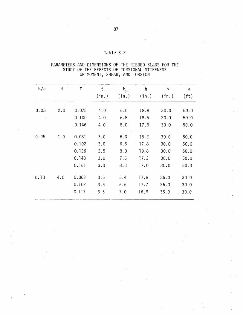
87
Table 3.2
PARAMETERS AND DIMENSIONS OF THE RIBBED SLABS FOR THE STUDY OF THE EFFECTS OF TORSIONAL STIFFNESS
ON MOMENT, SHEAR, AND TORSION
b/a H T t br h b a
(i n. ) ( in. ) (i n. ) (i n. ) (ft)
0.05 2.0 0.075 4.0 6.0 18.8 30.0 50.0
0.100 4.0 6.8 18.5 30.0 50.0
0.146 4.0 8.0 17.8 30.0 50.0
0.05 4.0 0.081 3.0 6.0 18.2 30.0 50.0
0.102 3.0 6.6 17.8 30.0 50.0
0.126 3.5 8.0 19.8 30.0 50.0
o. 143 3.0 7.6 17.2 30.0 50.0
0.161 3.0 8.0 17.0 30.0 50.0
0.10 4.0 0.063 3.5 5.4 17.8 36.0 30.0
0.102 3.5 6.6 17.7 36.0 30.0
o. 117 3.5 7.0 16.8 36.0 30.0

88
Table 4.1
MAXIMUM SIMPLE BEAM MOMENT AND SHEAR VS. SPAN
Span Length MB VB (ft) (K-ft) ( K)
40.0 49.5 5.0
57.0 101 .0 7.0
50.0 77.5 6.0
42.8 56.5 5.0
30.0 28.0 4.0

89
Table 4.2
MAXIMUM DEFLECTIONS OF ONE-SPAN RIBBED SLABS DUE TO MULTIPLE LOADS FOR MAXIMUM MOMENT
<5 (in.) Loading H b/a = 0.035 b/a= 0.05 b/a == 0.07
Perimeter Loads 2.0 0.7343 0.6152 0.4570
on the Edge 4.0 0.5557 0.7341 0.3474 Rib 6.0 0.5926 0.8549 0.3707
9.0 0.6947 ·0.5792 0.4298
Perimeter Loads 2.0 0.5856 0.4712 0.3540 on the Second 4.0 0.4370 0.5586 0.2675 Rib 6.0 0.4624 0.6496 0.2845
9.0 0.5391 0.4400 0.3304
Table 4.3
MAXIMUM DEFLECTIONS OF TWO-SPAN RIBBED SLABS DUE TO MULTIPLE LOADS FOR MAXIMUM POSITIVE MOMENT
<5 (in.)
b/a=O.10
0.1686 0.1310 0.1411 0.1655
0.1235
0.0956 0.1026 0.1210
Loading H b/a = 0.035 b/a = 0.05 b/a = 0.07 b/a = 0.10
Perimeter Loads 2.0 0.5272 0.4409 0.3283 0.1226
on the Edge 4.0 0.4002 0.5283 0.2504 0.0958
Rib 9.0 0.5034 0.4191 0.3118 0.1224
Perimeter Loads 2.0 0.4124· 0.3320 0.2495 0.0878
on the Second 9.0 0.3813 0.3119 0.2352 0.0886
Rib
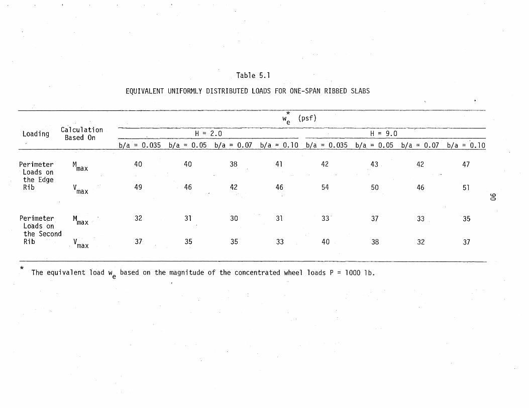
Loading
Perimeter Loads on the Edge Rib
Ca 1 culati on Based On
Mmax
Vmax
Perimeter M L6adson max the Second Rib V max
* .
Table 5.1
EQUIVALENT UNIFORMLY DISTRIBUTED LOADS FOR ONE-SPAN RIBBED SLABS
* we (psf)
H = 2.0 H = 9.0
b/a= 0.035 b/a = 0.05 b/a = D.07 b/a = 0.10 b/a = 0.035 b/a = 0.05 b/a = 0.07 b/a = 0.10
40 40 38 41 42 43 42 47
49 46 42 46 54 50 46 51
32 31 30 31 33" 37 33 35
37 35 35 33 40 38 32 37
The equivalent load we based on the magnitude of the concentrated wheel loads P = 1000 lb.
1..0 C>

Table 5.2
EQUIVALENT UNIFORMLY DISTRIBUTED LOADS ON TWO-SPAN RIBBED SLABS
* (psf) we Calculation Loading. Based On H == 2.0 H == 9.0
b/a == 0.035 b/a == 0.05 b/a == 0.07 b/a == 0.10 b/a == 0.035 b/a == 0.05 b/a == 0.07 b/a= 0.10
Perimeter Mm'ax 41 40 40 43 46 44 44 50 (at 0.44 Span)
Loads Vmax 44 48 45 48 56 54 49 54
. on the (at Exterior Support)
Ed,ge Rib . Mmax 47 44 42 45 54 51 48 52 (at Interior
U)
Support) .......
Vmax 68 64 60 56 81 73 68 67 (at 0.95 Span)
Perimeter Mmax 33 31 31 31 ... 33 33 33 36 (at 0.44 Span)
Loads V . max 38 37 33 34 41 40 37 39
on the (a t Exteri or Support) .
Second Mmax 32 31 31 32 34 34 35 37 (at Interior
Rib Support) Vmax 43 41 42 40 '48 47 48 47
(at 0.95 Span)
* The equivalent load we based on the magnitude of the concentrated wheel loads P = 1000 lb.
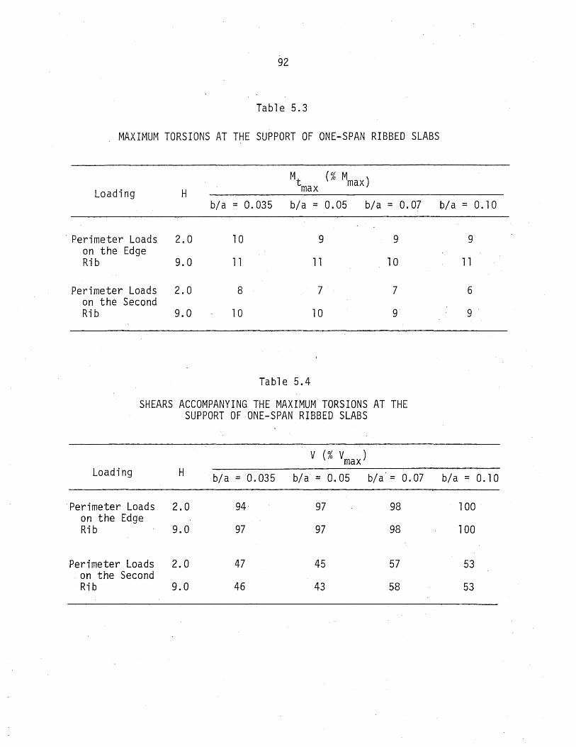
92
Table 5.3
MAXIMUM TORSIONS AT THE SUPPORT OF ONE-SPAN RIBBED SLABS
Mt (% Mmax) Loading H max
b/a = 0.035 b/a = 0.05 b/a = 0.07
, Perimeter Loads 2.0 10 9 9 on the Edge Rib 9.0 11 11 10
Perimeter Loads 2.0 8 7 7 on the Second Rib 9.0 10 10 9
Table 5.4
SHEARS ACCOMPANYING THE MAXIMUM TORSIONS AT THE SUPPORT OF ONE-SPAN RIBBED SLABS
V (% Vmax ) Loading H b/a = 0.035 bfa' = 0.05 bfa' = 0.07
'Perimeter Loads 2.0 94 97 98 on' the Edge Rib 9.0 97 97 98
Perimeter Loads 2.0 47 45 57 "on the Second
Rib 9.0 46 43 58
b/a=0.10
9
11
6
9
b/a == 0.10
100
100
53
53

93
Table 5.5
MAXIMUM TORSIONS AT THE EXTERIOR SUPPORT OF TWO-SPAN RIBBED SLABS
Loading H b/a = 0.035 b/a = 0.05 b/a = 0.07 b/a = 0.10
Perimeter Loads 2.0 8 8 7 on The· Edge Rib 9.0 9 9 9
Perimeter Loads 2.0 8 7 6 on the Second Ri-b . 9.0 10 9 8
Table 5.6
SHEARS ACCOMPANYING THE MAXIMUM TORSIONS AT THE EXTERIOR SUPPORT OF TWO-SPAN RIBBED SLABS
8
9
6
8
V (% Vmax at Exterior Support) Loading H b/a = 0.035 b/a = 0.05 b/a = 0.07 b/a =0.10
Perimeter Loads 2.0 94 96 96 98 on the Edge Ribs 9.0 96 97 97 99
Perimeter Loads 2.0 41 .39 49 48 on the Second Rib 9.0 41 37 50 50

Loading
Perimeter Loads on the Edge Rib
Perimeter Loads on the Second Rib
94
Table 5.7
MAXIMUM TORSIONS AT THE 0.95 SPAN LOCATION IN TWO-SPAN RIBBED SLABS
M t max (% Neg. Mmax)
H b/a = 0.035 b/a .= 0.05 b/a = 0.07
2.0 7 7 6
9.0 7 7 7
2.0 8 6 6
9.0 9 9 8
Table 5.8
SHEAR ACCOMPANYING THE MAXIMUM TORSIONS AT THE 0.95 SPAN LOCATION IN· TWO-SPAN RIBBED SLABS
V (% Vmax at 0.95 Span) Loading H b/a = 0.035 b/a = 0.05 b/a = 0.07
Perimeter Loads 2.0 70 73 74 on the Edge' Rib 9.0 69 72 74
Perimeter Loads 2.0 45 51 54 on the Second Rib 9.0 42 48 53
b/a=O.lO
6·
7
6
8
b/a= 0.10
74
74
57
55

95
Table 5.9
NEGATIVE BENDING MOMENTS ACCOMPANYING THE MAXIMUM TORSIONS AT THE 0.95 SPAN LOCATION IN TWO-SPAN RIBBED SLABS
: ..
M (% Neg. Mmax) Loading H b/a = 0.035 b/a = 0.05 b/a = 0.07
Perimeter Loads 2.0 51 50 51 on the Edge Rib 9.0 50 50 50
Perimeter Loads 2.0 40 52 r~
0-:)
on the Second Rib 9.0 41 53 54
Table 5.10
TORSIONS ACCO~1PANYING THE MAXIMUM SHEARS AT THE EXTERIOR SUPPORT IN TWO-SPAN RIBBED SLABS
Mt · (% POSe Mmax) Loading H b/a = 0.035 b/a = 0.05 b/a = 0.07
Perimeter Loads 2.0 8 7 7 on the Edge Rib r\ r\ , , , , '1"\ ::1. V I I I I IV
Table 5.11
TORSIONS ACCOMPANYING THE r,1AXIMUM SHEARS AT THE 0.95 SPAN LOCATION IN TWO-SPAN RIBBED SLABS
Mt (% Neg. Mmax)
Loading H b/a = 0.035 b/a = 0.05 b/a = 0.07
Perimeter Loads 2.0 3 3 3 on the Edge Rib 9.0 4 4 · 4
b/a = 0.10
50
49
rr 00
54
b/a = 0.10
8
, , I I
b/a=O.lO
3
5

96
A Center Lines of the Ribs
A.J I .. a
(a) One-Span Ribbed Slab
A.J J ...
a
(b) Two-Span Ribbed Slab
b
Simply Supported
Section A-A
B..J .. I ..
u
u
(/')
..0
Simply Supported
a
Section B-B
.1
u ......... u .c CE;
(/')
.c 'r->-
,......
o u \lr Equivalent br .5-'
Tapered Cross Section FIG. 1.1 TYPICAL RIBBED SLABS AND CROSS SECTIONS

Beam Element
Z
97
Slab Element
Forces at the Junction of Beam and Slab Elements
aM M + -zdx z ax aM
M + ~ dx x ax aM
II-+-~ My + at- dx
F Z
p
Z
aF v _ F + -" dx x ax
aF F + ~dx y oX
aF F + _z dx
Z ax
Internal Moments and Joint Forces Internal Forces and the Applied Load
Small Element of Beam
FIG. 2 .. 1 INTERNAL FORCES AT THE JUNCTION OF BEAM AND SLAB ELEMENTS, AND,ON A SMALL ELEMENT OF BEAM

98
0.50----~----~----~----~--~
Moment Diagrams Moment Diagrams 0.40
Ri b No.:
0.20
0.10
o~~~----~----~----~--~
1.00~--~----~----~---.----~
0.80 Shear Diagrams Shear Diagrams
>.r:tJ 0.60 Ri b No.: ..........
::>
0.40
0.20/--_____ _
O~ __ ~ ____ ~ ____ ~ __ ~ __ ~_
0.40, I I T .... ""'c:';n.., n;~I"1""~rn ... I VI ..::I I VII Lli U~:p UIII":;'
0. 30r-_
0.10
. Rib No.:
o~--~----~----~--~-----
Rib No.:
6
I I Torsion Diagrams
Ri b No.:
o o. 1 0 O. 20 O. 30 0 . 40 0 .:s a . 0 O. 1 0 O. 20 0 . 30 0 . 40 O. 50
Distance from Support/a Load at midspan on the edge rib
Distance from Support/a. Load at midspan on the center rib
FIG. 3.1 MOMENT, SHEAR, AND TORSION DIAGRAMS FOR A ONE-SPAN RIBBED SLAB DUE TO A SINGLE LOAD AT MIDSPAN ON THE EDGE AND CENTER RIBS

99 0.40
0.30 Moment Diagrams
0.20
0.10 co
::a: -.. ::a: 0
-0.10
-0.20
1 .00 ~
~ 0.80
0.60 Rib No.: Shear Diagrams
0.40
0.20 2
co 0 4 > -.. >
-0.2
0.3~~--~~--~~--r-.--.--.--.--r--r~~'--.--.--r--r--r~
0.2 Ri·b No.: Torsion Diagrams
0.10 co
~ 0~----------~~------------4-------~~~--------------~ -!-l :::E
-0.1
Distance from End Support/a
(a) Load at Midspan on the Edge Rib
FIG. 3.2 MOMENT, SHEAR,AND TORSION DIAGRAMS FOR A TWO-SPAN RIBBED SLAB DUE TO A SINGLE LOAD AT ONE MIDSPAN ON THE EDGE AND CENTER RIBS

co > ......... >
Moment Di agrams,
Rib No.: Shear Diagrams
-0.6
-0.8
Torsion Diagrams
o. 1
o~--~~~--~--~~~~~~~==~~
-0.10
-0.20
-0.30 L-~~ __ ~~ __ L-~~ __ ~~ __ ~~~ __ ~~ __ ~~~ __ ~~~
o 0.20 0.60 0.80 0.80 0.60 0.40 Distance from End Support/a·
(b) 'Load at Midspan on the Center Rib
FIG. 3.2 (CONT.)
o

Rib No.9
Rib No.8
Rib No. 7
RihNo.:
101
Reaction Transmitted by Slab
Shear Diagrams
-----....;"""""IIIIIIa!I!I~fttttHfHttiHtitttHfl~~----- Fi rs t Adj acen t - Rib
FIG. 3.3 THE INTERPRETATION OF THE LOADING EFFECTS ON THE RIBS
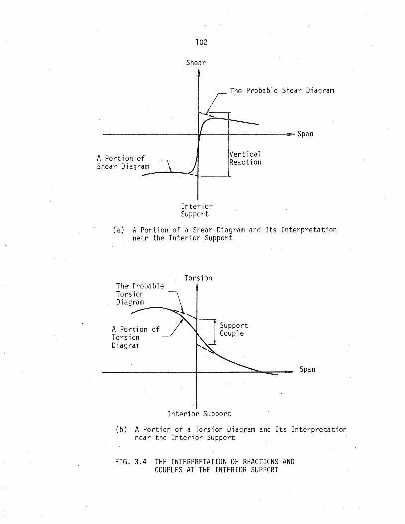
A Portion of Shear Diagram
102
Shear
Interior Support
Vertical Reaction
(a) A Portion ofa Shear Diagram and Its Interpretation near the Interior Support
A Portion of. Torsion Diagram
Torsion
Interior Support
Span
(b) A Portion of a Torsion Diagram and Its Interpretation near the Interior Support
FIG. 3.4 THE INTERPRETATION OF REACTIONS AND COUPLES AT THE INTERIOR SUPPORT
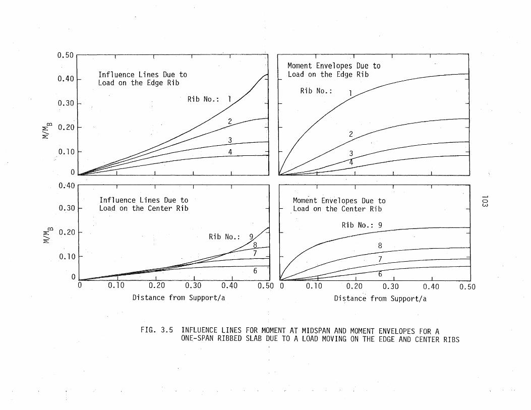
0.50
0.40
0.30
';2:.C:C 0.20 ......... ';2:.
0.10
0
0 .. 40
0.30
';2:.C:C 0.20 ......... ::E:
0.10
0 0
Influence Lines Due to Load on the Edge Rib
Rib No.:
Influence Lines Due to Load on the Center Rib
0.20
Rib No.:
0.40 Distance from Support/a
6
0.50 0
Moment Envelopes Due to Load on the Edge Rib
Rib No.:
Moment Envelopes Due to Load on the Center Rib
Rib No.: 9
0.10 0.20 0.30 0.40
Di~tanc~ from Support/a
FIG. 3.5 INFLUENCE LINES FOR MOMENT AT MIDSPAN AND MOMENT ENVELOPES FOR A ONE-SPAN RIBBED SLAB DUE TO A LOAD MOVING ON THE EDGE AND CENTER RIBS
0.50
o w

co ::'E ......... ::'E
co ::E ......... ::'E
0.50
0.40
0.30
0.20
0.10
0
-0.10
-0.20
-0.30
0.30
0.20
0.10
0
-0.10
104
Influence Line for Moment at Midspan
Rib No.:
Influence Line for Moment at Interior Support
Influence Line for Moment at Midspan
Rib No.:
Influence Line for Moment at Interior Support
Moment
Ri b No.:
Influence Line for Moment at the Other Midspan
Load on the Edge Rib
Moment Rib No.:
Influence Line for Moment at the Other Midspan
Load on the Center Rib -0.20 L-__ -L ____ ~ __ ~~ __ ~ ______ ~ __ ~ ____ ~----~--~ ____ ~
o 0.20 0.40 0.60 0.80 1.00 0.80 0.60 0.40 0.20
Distance from End Support/a
FIG. 3.6 INFLUENCE LINES FOR MOMENT AT MIDSPAN, AND MOMENT ENVELOPES FOR A TWO-SPAN RIBBED SLAB DUE TO A LOAD MOVING ON THE EDGE
. AND CENTER RIBS ~
o

1 .00
0.90
0.80
0.70
0.60
:> 0.50
0.·40
0.30
0.20·
0.10
Unit Load on the Edge Rib Unit Load on the Center Rib
Rib No.: Rib No.:
0.20 0.40 0.60 Distance from Support/a Distance from Support/a
FIG. 3.7 INFLUENCE LINES FOR SHEAR AT THE SUPPORT OF A ONE-SPAN RIBBED SLAB DUE TO A LOAD MOVING ON THE EDGE AND CENTER RIBS
0.80 1 .00
o Ul

>
0.4
0.2
-0.2
-0.4
-0.6
-0.8
0.20
0
-0.20
-0.40
-0.60
-0.80
-1.00 0
106
Influence Lines for r Shear at the Exterior Support
Influence Lines for Shear at the 0.95 Span Location
Rib No.:
Influence Lines for r- Shear at the Exterior
Support
Influence Lines for Shear at the 0.95 Span Location
Unit Load on Edge Rib
Unit Load on Center Rib
0.20 0~40' 0.60 0.80 1.00 0.80 0.60 0.40 0.20 0
Distance from End Support/a
FIG. 3.8 INFLUENCE LINES FOR SHEAR AT THE EXTERIOR SUPPORT AND AT THE 0.95 SPAN LOCATION OF A TWO-SPAN RIBBED SLAB DUE TO A LOAD MOVING ON THE EDGE AND CENTER RIBS

107
0.05 ~--~--~----'---II---.--~r----r--~----'---I
Rib No.: Unit Load on the Edge Rib
0.04
0.03
0.01
OL---~--~ ____ ~ __ ~ __ ~ ____ ~ __ ~ __ ~ ____ ~ __ ~
0.03 ~--~--~----~--~---'----'---'----'----'---I
Unit Load on the Center Rib 0.02 Rib No.:
1.00 Distance from Support/a
FIG. 3.9 INFLUENCE LINES FOR TORSION AT THE SUPPORT OF A ONESPAN RIBBED SLAB DUE TO A LOAD MOVING ON THE EDGE AND CENTER RIBS

ca ~ '-..
+l :E:
0.05
0.04
0.03
0.02
. 0.01
0
-0.01
-0.02
-0.03
-0.04
0.03
0.02
0.01
-0.01
108
Ri b No.: Influence Lines for Torsion at the Exterior Support
Influence Lines for Torsion at the 0.95 Span Location
Rib No.: Influence Lines for Torsion at the ·Exterior Support
Unit Load on the Edge Rib
Unit Load on the Center Rib
Influence Lines for Torsion at the 0.95 Span Location
-0.02L-__ ~~ __ ~ ____ -L ____ ~ ____ ~----~--~~--~----~----~ o 0.20 0.40 0.60 1.00 0.80 0.60 0.40 0.20
Distance from End Support/a
FIG. 3.10 INFLUENCE LINES FOR TORSION AT THE EXTERIOR SUPPORT AND AT THE 0~95 SPAN LOCATION OF A TWO-SPAN RIBBED SLAB DUE TO A LOAD MOVING ON THE EDGE AND CENTER RIBS
o

0.70
0,60
0.50
0.4.0
co :E 0.30 ........... :E
0.20
0.10
0
0,70
0,60
0.50
0.4.0
co :E 0.30 ........... :::E'
0.20
O. to
a
0.70
0.60
0.50
D.ltO co
:::E' ........... ::E: 0.30
0.20
0.10
a
" , "-"-
1 2 3
109
Regular Edge Rib
Double-Width Edge Rib
Moment Envelope
Moment Distributions
Triple-Wi~th Edge Rib
Moment Envelope
Moment Disiributions
li 5 6
Rib Number 7 B s
FIG. 3.11 MOMENT ENVELOPES AND MOMENT DISTRIBUTIONS AT MIDSPAN OF VARIOUS RIBS OF A ONE-SPAN RIBBED SLAB WITH THE REGULAR AND STIFFENED EDGE RIBS DUE TO A LoAD MOVING'ALONG MIDSPAN
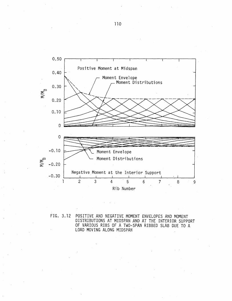
110
FIG. 3.12 POSITIVE AND NEGATIVE MOMENT ENVELOPES AND MOMENT DISTRIBUTIONS AT MIDSPAN AND AT THE INTERIOR SUPPORT OF VARIOUS RIBS OF A TWO-SPAN RIBBED SLAB DUE TO A LOAD MOVING ALONG MIDSPAN

co :E: ..........
>< rt! E
::E
co >-..........
>< rt! E
>-
co ::E ..........
>< rt! E
+-> ::E
111 .
0.60 H ~ 4 0 b ..... ---..:.-., Ia..:::. .10 --.......... _-...
0.50 .
0.40
0.30
G-____ !~ 4.0, b/a ::: .05 .... -- ~ = 2 -0 b ..... 7 -----· - - ...... - - --:. ~ -!::!.I.,S... = ...D.5-- - --e
• H :::; 4, bl a, ::: .~ 10 .' - ~ . 8 @
0.20 II H = 4. 0 ,. ~/ a, = . 0i H ::: 2.0, b/a, = .05
0.10
o b-__ ~ __ ~ __ ~ __ ~~~ __ ~~~~~~~~ __ ~
0.50 .... -l!.:.~. 0, b/a = .10
0.40 ----..... __ ...
0.30
0.20
0.10
0,
0.05
0.04
0.03
0.02
0.01
__ H = 4.0; b/a::: 05 e- __ --:..-=---&--. -_.........:.._....:._. : .. ----.=------ ~--- ........
•• uHr _::---A4-. riO ,~·"'Lb /'-a:--=-."""'=;l·~-·-.-· . ....... iT ;-~ 0-:-~ = . 05. ' ... 1 .... • H= 4~0, b/a =.05
@Ii " II -~ ~
-H = 2.0, b/a =.05 .
T
Load at Midspan on the Edge Rib Load at Midspan on the Center Rib
FIG. 3.13 EFFECTS OF TORSIONAL STIFFNESS ON MOMENT, SHEAR AND TORSION

co L -.... ::2:
co ~ -.... L
0.70
o.6ol bja = 0.035 bja = 0.05 Load on the Load on the
0.50 L Edge Rib H = 9.0
Edge Rib H = 9.0
o.qOWH = 'I.U Load on the H = 4.0
H = 2.0 Center Rib ;; H = 2.0
0.30 . H = 9 0 . ----, -t ~ " '\." H = 4.0
0.20 I ~ H =.2.0
0'.10
0
0.70 I
Load on the 0.60 L Load of the bja = 0.07
Edge Rib Edge Rib bja=O.lO H = 9.0
0'.50 ~ / H = 9.0 H = 4.0 H = 4.0
Load on the H = 2.0
o.qOf,\ Center Rib H = 9.0 ~
0'.30 H = 4.0 H = 2.0
0'.20
0.10
0 2 3 It 5 6 7 8 9 2 3 It 5
Rib Number Rib Number
FIG. 3.14 MOMENT DISTRIBUTIONS AT MIDSPAN OF ONE-SPAN RIBBED SLABS DUE TO SINGLE LOADS AT MIDSPAN ON THE EDGE AND CENTER RIBS
6
Load on the Center Rib
H =
I N
Load on the Center Rib
H = 9.0 H = 4.0
7 B 9

0.10
0.60 _ b/a = 0.035 b/a = 0.05
0.50 L Load on the Load on the Edge Rib
0.40 L Edge Rib H = 9.0
f 0.30Ur H ~ 2.0
0.20 r , 0.10
0
0.10
0.60 l Load on the
0.50 L Edge Rib H = 9.0 o.qOW H ~ 2.0
o::::l :::E .......... L 0.30
0.20
0.10
0 "2 3
H = 9.0 Load on the H = 2.0 Center Rib H = 9.0 H = 2.0 ="
b/a = 0.07 Load on the b/a = O. 10 Edge Rib
,-H = 9.0
Load on the
J KH ~ ~.U Center Rib
H : 9.0 ~ H - 2.0 --.
4 5 6 7 8 9 2 3 4 5 6
Rib Number Rib Number
FIG. 3.15 POSITIVE MOMENT DISTRIBUTIONS AT MIDSPAN OF TWO-SPAN RIBBED SLABS DUE TO SINGLE LOADS AT MIDSPAN OF THE EDGE AND CENTER RIBS
Load on the Center Rib
H = 9.0 H = 2.0
--I
w
Load on the Center Rib
H = 9.0 H = 2.0
7 8 9

0.70~1 ----~------~----~----~----~----~._----._----I
co :::E::
0.60
o.so
0.40
~ 0.30 :::E::
0.20
0.10
o
Load on the Edge Rib
H= 9.0 H == 2.0
b/a == 0.035
Load on the Center Rib
H·= 9.0 H = 2.0
0.70~1 ----~------~----~----~----~----~~----~----.
0.60 ~.
0.50 ~.
0.40 co
:a:: ~ :::E:: 0.30
0.20
0.10
o . 1
Load on the Edge Rib
H = 9.0 H = 2.0
2 3
b/a = 0.07
4 5 5
Rib Number
Load on the Center Rib
H = 9.0 H= 2.0
7 B 9
Load on the Edge Rib
H = 9.0
H = 2.n
Load on the Edge Rib
H = 9.0 H = 2.0
2 3
b/a = D.n5
b/a=0.10
4 5
Rib Number 6
Load on the Center Rib
H = 9.0 H = 2.0
Load on the Center Rib
7 B
FIG. 3.16 NEGATIVE MOMENT DISTRIBUTIONS AT THE INTERIOR SUPPORT OF TWO-SPAN RIBBED SLABS DUE TO SINGLE LOADS AT MIDSPAN ON THE EDGE AND CENTER RIBS'
..j::::.
9

O.70~, ----~----~----~~----~----~----._----_.----I
0.60
0.50
ro 0.4.0 :> ........... :>
0.30
Load on the Edge Rib
H = 9.0 H = 4.0 H = 2.0
0.20 t- I ,
b/a = 0.035
Load on the Center Rib H = 9.0 H = 4.0 H = 2.0
o.~o~ I =======-~ O.70~, ----~--~----~--~~--_.----._----._--I
ro :>
0.60
Load 0.50 LEdge
0.4.0
........... 0.30 :>
0.20
0.10
o 2
= 9.0 4.0
= 2.0
3
b/a = 0.07
Load on the Center Rib
H = 9.0 H = 4.0 H = 2.0
4. 5 6 7
Rib Number B 9
Load on the Edge Rib
H = 9.0 H = 4.0 H = 2.0
Load on the· Edge Rib
2
H = 9.0 H = 4.0 H = 2.0
'3
b/a = 0.05
Load on the Center Rib H = 9.0 H = 4.0 H = 2.0
b/a = 0.10
Load on the Center Rib
H = 9.0
4. 5 6 7
Rib Number
FIG. 3.17 SHEAR DISTRIBUTIONS AT THE SUPPORT OF ONE-SPAN RIBBED SLABS DUE TO SINGLE LOADS AT MIDSPAN ON THE EDGE AND CENTER RIBS
(Jl
B 9

0.70 I . I . I
0.60
o.so
ro > 0.40 ........... >
0.30
0.20
0.10
o
Load on the Edge Rib
H = 9.0 H = 2.0
b/a = 0.035
Load on the Center Rib
H 9.0 H = 2.0
0.70-1------~--------__ ~----~~----~----~----~._--~
ro > ........... >
0.60
0.50
0.20
0.10
o
Load on the Edge Rib
2
H = 9.0 H =2.0
3
b/a = 0.07
456
Rib Number
Load on the Center Rib
H= 9.0 H = 2.0
7 8 9
Load on the Edge Rib
H = 9.0 H = 2.0
Load on the Edge Rib
2
H= 9.0 H = 2.0
3
b/a =0.05
Load on the Center Rib
H = 9.0 H = 2.0
b/a = 0.1n
Load on the Center Rib
H = 9.0
5 IS 7 B
Number
FIG. 3.18 SHEAR DISTRIBUTIONS AT THE EXTERIOR SUPPORT OF THE LOADED SPAN OF TWO-SPAN RIBBED SLABS DUE TO SINGLE LOADS AT MIDSPAN oN THE EDGE AND CENTER RIBS
O'l
9

PIG. 3.19 SHEAR DISTRIBUTIONS AT THE 0.95 SPAN LOCATION OF THE LOADED SPAN OF TWO-SPAN RIBBED SLABS DUE TO SINGLE LOADS AT MIDSPAN ON THE EDGE AND CENTER RIBS

O.07~1 ____ ~-L--~----._----._~--._----._----._--~
0.06
0.05
O.Ol!
Load on the Edge Rib
kiH =9.0 H = 4.0
.. ~iH = 2.0 co 0.03 F ' ( ( ::z:: J J
............ +->
::E: 0.02 I
b/a = 0.035
Load on the' Center Rib H = 9. 0 --'----. H = 4.0 H = 2.0
a·OI h ~
o
O.07~1 ----~--~----._--_.----II----._--~---: Load on the Edge Rib 0.06
0.05
co :E 0.0l! ............
+-> ::z:: O. 03 r:-------L-
0.02
0.01
o 2
H = 9.0 H = 4.0 H =2.0
3 I! 5
b/a = 0.07
Load on the Center Rib
H = 9.0 H = 4.0 H = 2.0
6 7 '8
Rib Number 9
Load on the Edge Rib
H = 9.0 H= 4.0
H = 2.0
I I
Load on the Edge Rib
H= 9.0
2 3 I! 5
b/a = 0.05
Load on the Center Rib
H = 9.0 H = 4.0 H = 2.0
b/a = n.10
Load on the Center Rib
H = 9.0 H = 4.0 H =
6 7 8
Rib Number
FIG. 3.20 TORSIONAL MOMENT DISTRI~UTIONS AT THE SUPPORT OF ONE-SPAN RIBBED SLABS DUE ' TO SINGLE LOADS AT MIDSPAN ON THE EDGE AND CENTER RIBS
co
9

0.07
0.06
0.05
0.04 co
:E ............
+> 0.03 :E
0.02
0.0l
0
0.07
0.06
0.05
0.04
,co :E 0.03 ............
+> :E
0.02
0.01
0 1
Load on the Edge Rib
H = 9.0 H =2.0
Load on the Edge Rib
2
H = 9.0 H = 2.0
3
bla = 0.035
II
Load on the Center Rib
H = 9.0
H = 2.0
b/a = 0.07
5
Load on the Center Rib H = 9.0 H = 2.0
6 7 8
Rib Number
9
bla = n.05
Load on the Edqe Rib
H = 9.0
H = 2.0 Load on the Center Rib H = 9.0 H = 2.0
bla = 0.10
Load on the
2
Edge Rib H = 9.0 H = 2.0
3 II 5
Load on the Center Rib
H = 9.0
H = 2.0
6 7
Rib Number'
8
FIG. 3.21 TORSIONAL MOMENT DISTRIBUTIONS AT THE EXTERIOR SUPPORT OF THE LOADED SPAN OF TWO-RIBBED SLABS DUE TO SINGLE LOADS AT MIDSPAN ON THE EDGE AND CENTER RIBS
I.D
9
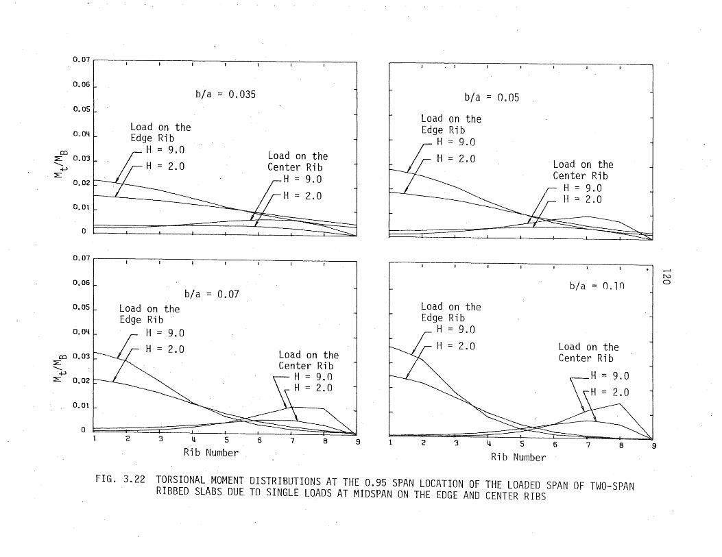
0.07
0.06
0.'05
0.04
CO L 0.03 ..........
+-> L
0.02
0.01
0
0.07
0.06
0.05
0.04
CO 0.03 L ..........
+-> L 0.02
0.01
0
b/a = 0.035
Load on the Edge Rib
H = 9.0
H = 2.0
Load on the Edge Rib
H = 9.0
H = 2.0
2 :3
I·
b/a = 0.07
II 5 6
Rib Number
Load on the Center Rib
H = 9.0
H'= 2.0
Load on the Center Rib
H = 9.0 H = 2.0
7 B 9
b/a = 0.05
Load on the Edge Rib
H = 9.0
H = 2.0
Load on the Edge Rib
H = 9.0
Load on the Center Rib
H = 9.0 H = 2.0
b/a = O.ln
Load on the Center Rib
2 :3 II 5 6 7 B
Rib Number
FIG. 3.22 TORSIONAL MOMENT DISTRIBUTIONS AT THE 0.95 SPAN LOCATION OF THE LOADED SPAN OF TWO-SPAN RIBBED SLABS DUE TO SINGLE LOAnS AT MIDSPAN ON THE EDGE AND CENTER RIBS
9
N o

121 0.70 .
0.60
0.50
co 0.40 :,'E ...........
>< I'tS 0.30 :,'EE
0.20
0.10
o ~~~ ____ ~ ______ -L ______ ~~ ____ ~ ____ ~ ____ ~~
0.035 0.05 0.07 0.10
b/a
0.70 ----.,.....---r-----r----,.------r----..---~
0.60 b/ a==O.lO _----__e__---...e------------- b/a == 0.07 -+-. __ -- ----. -----.......----0.50
_ b~-=-Ch.02- --+- - --- - _._----.....--- 35 . b/a == 0.10
b/a == ~_ ---0.40
co :,'E
'x 0.30 _ ...... ---
b/a == 0.07 n::s E
:,'E
L:==========~------_=============Jb~/~a~=~OJ.0~3~5==~ 0.20 E
b/a = 0.05
o. 1 0,:
o ~ ____ ~ ______ ~ ____ ~ ______ ~ ____ ~ ____________ ~ 2.n 4.0 6.0 9.0
H
- - Load at Mi dspan on the Edge Ri b ---- Load at Midspan on the Center Rib
FIG. 3.23 VARIATIONS OF .MAXIMUM MOMENT WITHH AND b/a FOR ONE-SPAN RIBBED SLABS UNDER SINGLE LOADS AT MIDSPAN ON THE EDGE AND CENTER RIBS

co ;:E:
'-. x' rt:S
;:E:E
122
0.70
0.60 Positive Moment at Midspan
0.50
0.40
0.30
U ::: 9.0 _-n _---_--11'0 --._..._- U ::: "t. _-....- n ---- . ---0 _-- _---u ::: Z. ---__ __..e-- n_---
......-- --- ........ ---.-...'---------- - - --
-""'--- --- ----- --- ----- --- -----0.20
0.10
0
-0.10 H = 2.0
-0.20
-0.30
-==::::-_ H = 9.0 _ -- =:t----_ ---.:::J::'------- ........ - H = 20 ------. - ....... -----~------- ....-.~-- ----. Negative Moment at - - - -H = 9 0 - -=--=-= the Interior Support .
-0.40 __ ~~ ____ ~ ______ ~ __ ~ __ ~ ____ ~ ______ -L ____ ~
0.035 0.05 0.07 0.10
b/a
--Load at Midspan on the Edge Rib -- Load at Mi dspan on the Second Ri b
FIG. 3.24 VARIATIONS OF MAXIMUM POSITIVE AND NEGATIVE MOMENTS WITH HAND b/a FOR TWO-SPAN RIBBED SLABS UNDER SINGLE LOADS AT MIDSPAN ON THE EDGE AND CENTER RIBS

123
O. 60 ---rl----~I----rl----,...-I---,-'---Ilr----,
0.50 ~ -H=9.0~ -4 ..-- ..... ---::.....c H = 6.0 --::..-- - _....:4 --- -- .......... --- ..,.,. -- --- ::. -=-...... --- ,.".,.... --- """0
0.40 i-
,..,.. -,:::t::.: - --4(.\-\ = 4. --~ ~ -~-~--- ---- -2" O. 30 f- _ - ::: - _ - _ - - "'tu = '2.0
o -:;:::-::::-- ____ -- n - _.....ft:"'-_-_-rt:S -_::::::IF- --- u - 9 0 .....01
_E o.20t~-:-:-:-~~::-~~~:-~-~~~~~~~~~~f\~-~.~~~~~ - ..... ~:::,::..---- --~ -- ~ ~- . I
.--::: i'
0.10 . - H _ 6.01 LH ~ 2.0 -H = 4.0
co >-..........
>< I'd E
>-
o I 1 0.05
I I I
0.035 0.07 0.10 b/a
0.60 I I I I I I
0.50 f0- -
0.40
0.30
b/a = 0.10 .. . __ ---~ .....-.- ------ . , .... -------- .------- 07 . _----4 1,...--- b/a =Jl.:..----e---- ----~---- -f- . __
0.20 ~------- b/a = _O...:..O~-+--- ra.-::-rrTn- --~ -- --e------ 0 a - . ...... ---- 035 ~ t- b/ a = O. -& - bl - 0 07
0.10
-- ...... -,...::::.-- ..... a - . t;:":--":::'=- ~ h/a = 0.05 Ii-
0 2.0
-
I I I I
4.0 6.0
H
Load at Midspan on the Edge Rib Load at Midspan on the Center Rib
b/a =0.035 I I
9.0
FIG. 3.25 VARIATIONS OF MAXIMUM SHEAR AT THE SUPPORT WITH HAND b/a FOR ONE-SPAN RIBBED SLABS UNDER SINGLE LOADS AT MIDSPAN ON THE EDGE AND CENTER RIBS

co >-"-..
x f'1j
E >-
co >-"-.. x
f'1j
E >-
124
0.70 ~----'----~I-------~I-----"-------'l-------r-,-----,
0.60 f- Maximum Shear at the Exterior Support -
O. 50 f- -
0.40
0.30
0.20
0.10
0
0.80
0.70
0.60
0.50
0.40
0.30
0.20
0.10
\-\ :: 9.0 _---~ ---- --------__ - U :: 2.0 _--~ _-- f\ _---
_____ - _ --0-- - - --- ----- ---10-0- .....-I" __ ,....--- H - 9.0
-- H :: 2.0 -
I I j ~ I 1
Maximum Shear at the 0.95 Span Location
--U :: 9.0 _----n _----------- -__ -- \J :::: 2. 0 __ ----__ --. n_-.,....--- ------- ----------- -----. ---------,.....-
----"" -""----""
H :: 2.0
-
o 0.035 0.07 0.10
b/a
Single Load at One Midspan on the Edge Rib Single Load at One Midspan on the Center Rib
FIG. 3.26 VARIATIONS OF MAXIMUM SHEAR AT THE EXTERIOR SUPPORT AND 0.95 SPAN LOCATION WITH HAND b/a FOR TWO-SPAN RIBBED SLABS UNDER SrNGLE LOADS AT MIDSPAN ON THE EDGE AND CENTER RIBS

co :E '-- x
rcr E
+-l :E
0.06
0.05
0.Q4
0.03
0.02
125
~ : ~:~ ) H = 4.0 _------ ---- ------- ------- ...-.-- --- ---- ---- --- ----.--- --- ---- ---- ---
--...- ----- - ----...-- --....,..-- ...- - -.-...- 0 ...- ......---- ----- rH ::: s.:...---
-" ......... ...- -- --1---...-..,;".. .......... ........-- .. ----...... -- .-- -~ - ......... --- ------ _-0----- H = 9.0
::: 6.0
o ~~~ ____ ~ ______ ~ ______ ~~ ____ ~ ____ ~ __ ~ __ ~ 0.035 0.07 0.10
b/a
0.06 __ ----~------~----~------~----~------~----~
b/a::: 0.10_---..------........-----------__ ........... ---- bh/a = 0.07 ___ ~
0.05
....,...,. ~---__ ..... __ ._ ..... _ .... __ .... __ ......... ____ .'-__ n._OL .-:-----~-~.~.-.---~-----------~~-= :::!"'--=-=..--.-o-no-.- _ ............. - ... -....... -- _ ...... _- .-.--.-... -
--- -- bil::: .------.---- --~-- --co ___ --- ---e------~ x 0.03 _-...----- _---o---QL~~Q.:..035 ___ -
rcr --4iB'-" - -- . . ..
+-lE ---L 0.02
o ~ ____ -L ______ L_ ____ ~ ______ ~ ____ ~ ______ ~ ____ ~
2.0 4.0 6.0 9.0 H
---- Load at Midspan on the Edge Rib --.-- Load at Midspan on the Center Rib
FIG. 3.27 VARIATIONS OF MAXIMUM TORSION AT THE SUPPORT WITH HAND b/a FOR ONE-SPAN RIBBED SLABS UNDER SINGLE LOADS AT MID- . SPAN ON THE EDGE AND CENTER RIBS

0.06
0.05
126
Maximum Torsion at the Exterior Support H = 9.0
-e-- - - H =--zr. D.:- _ -------- .....--.....-- --- --- ----- ....--.-- -- --- -:- -
0.04 ------ -- 2 0 ___ --- H = . _------ -- ----------- ---- ........ --....... ---- ------....... ..e----------H = 9.0 H = 4.0
~~::====~====== ____ --~------~H~=~2~.~0------~ 0.01t
O~ __ ~ ____ ~ ______ ~ ______ ~ ______ ~ ______ ~ ____ ~
0.06 I I I I I I
Maximum Torsion at the 0.95 Span Location 0.05~ -
O. 04~ -H = 9.0 _---4
--- -=-- - ---_e__---------..JIll-- -0~03~ -
----......... --.,~--H = 2.2-_---~ --e-------0.02 - __ -e--- ------ --- -- -
~....--- H = 9.0 o. 01 ~ ...
.- H - 2.0 - -
o I 1 1 I I I
0.035 0.05 0.07 0.10 b/a
Load at Midspan on the Edge Rib Load at Midspan on the Center Rib
FIG. 3.28 VARIATIONS OF MAXIMUM TORSION AT THE EXTERIOR SUPPORT AND 0.95 SPAN LOCATION WITH HAND b/a FOR TWO-SPAN RIBBED SLABS UNDER SINGLE LOADS AT MIDSPAN ON THE EDGE AND CENTER RIBS

co :E ..........
x n:s E
+l ::E
0.06
0.05
0.04
0.03
0.02
0.01
0 0.06
0.05
0.04
0.03
0.02
0.01
b/a = 0.035
b/a = 0.07 --.- H = 9 0 ~--......................... .
'?_-- .. " , Ii 1''' '.::: ........ " H = 6.0
/ ----'-... '~\~ H = 4.0 1// '.........'" H = 2.0
1/ " ' , II H = 9. 0................ " " , I H - 6 0 '" I - -. ,,,~,,
" ~~, I ~H = 4.c), "'. ~ I H = 2.0 ',~, I ~ -............... '''~~' I. '~
~ ~
0.2 0.4 0.6 0.8 1.0 0
b/a = 0.05 H = 9.0 .---- /i;. H::: 6.0 .1.::--- ....... "
/~.-- ....................... " ................. (f£ H = 4.0 ~/ ' ....... ', ........ , ----. , ....... % H = 2.0 - -- , // ......................::--...
/ ....... ,,' I 6 0 ,,,~~ ~f=.9.0 , ">'~ , . H =. , ,,~~
H - 4 0 ....... '::", ,
. -., """ 2 0 ......... ":-..:
I H =. '<:'\, I ~ '~ " ".
~ __ -:: ......... , b/a = 0.10 !/ -,"
/; <:::'<', (/;H = 9.0 ~-- " " '/.;' -- ......... , ,~"" H = 6.0
/1 '''''~H = 4 0 // ........,' . ,1/ H : 9.0'" 'AH = 2.0 I H - 6. 0 ",'\ ,,'\ I , ~~ J , ~~ I " ,,~ I ' ~~ , ~ I ,~
,~ ,~ ,,~
~.\.
0.2 0.4 0.6 0.8 1 .0 Distance from Support/a
-- Load on the Edge Ri b ---- Load on the Center Rib
FIG. 3.29 INFLUENCE LINES FOR TORSION AT THE SUPPORT OF VARIOUS ONE-SPAN RIBBED SLABS DUE TO A LOAD MOVING ON THE EDGE AND CENTER RIBS
--I
N -......J

128
0.07
0.06
H = 9.0 H = 6.0~ __ H = 4.0 __ -.-:-
--- ---- ---- ------- --- --- --- ~ ~ ---- ----------~ ---- ---- ------------- - ------- ------ -- ----..-.-~-------- ---~~~-- --T .,.".-::;;~:::""- -e-----H= 2.0 -::=:---:::...---"'- -----...- ----------
0.05
0.03 H = 9:0
0.02 H :: 4.0
'2§:::====::====~------+-------~HI=~2~.Oa-----~ 0.01 t;
O~~ ______ ~~ ____ ~ ______ ~ ____ ~~ ____ ~ ____ ~ 0.035 0.10
b/a
Load on the Edge Ri~ Load on the Center Rib
FIG. 3.30 VARIATIONS OF MAXIMUM TORSION AT THE SUPPORT WITH H AND b/a FOR ONE-SPAN RIBBED SLABS UNDER SINGLE LOADS ON THE EDGE AND CENTER RIBS

129
1 .5 1 51 3 I Center Line of Center Line of
11 I r· the Edge Rib the Second Rib
- -......-.--e--+- .......... a 1/ ,....
U • . " II • " . .. . II ......... • • fa • • • • • • • U
1.0 'I • • " . •• •• • l..() - • • • • • • • • • • N a
®
'I •• •• •• • • • t/')
lID lID "
«II • " " • • • -c .r-c::::
I. 40' .I I. 40' ./ f"-
/. 57 1 I. 57 1 I "'"I
Center Line of Center Line of the Edge Rib the Second Rib
- ........ ~ .......... -................... -a r-- 11
• •• • • • • •• •• • u - • • • •• • • •• • • • ......... 1.:0 U
• •• • • • • •• • • • - • • • •• • • •• •• • a a M
®
• •• • • • • • • •• CD t/')
- • CD • e • • • fa • •• e -c \.0 e " . • • • • " . • • • .r-
c:::: • • • " II •• • • II • • f"-
l. 501 m I I. 50' .j
Perimeter Loads on the Edge Rib Perimeter Loads on the Second Rib
• Concentrated Wheel Load P (a) Multiple loads for Maximum Moment on One-Span Ribbed Slabs.; for Two
Span, These are the Load Patterns on One~Span for Maximum Positive Moment, and on Both Spans the Patterns are for Maximum Negative Moment
FIG. 4.1 LOADING SYSTEMS FOR MAXIMUM BENDING MOMENTS, SHEARS, AND TORSIONAL MOMENTS

130
-Cen~EJr tine of Center line of 2.71 5' 3 1
the Edge Rib the Second Rib t 1 I r
-0 ...... \0
"" ., • • ee • e •• • LO
... • · '" -- e • @ @ • II \.0 • • • -. • • •• • u
CD • • • • • • • • • .......... - u 0 I"""""
• • • CD • • • •• • \0 ("I") • • • • e • • •• • 1..0 • • • •• • • • • CEJ • • • • • • • • •• • VI - ...c
0 .,.... ...... 0::::
• • • ../ • • •• • "" .. • • • • •• •• • ...... I I I I~
I. 50' ./ I~ 50' '~ I'~'" ,"'"
0.5' 5 1 3' Center Line of Center line of
1/- I -I the Edge 'Rib the Second Rib
-0 ...... = •• • • •• \.0 - •• f) • •• ,......
1..0 LO
•• • • •• II - • • •• •• 0 u ...... ..........
•• • • u •• -\.0 • • •• •• \.0 •• • • •• ("I")
• • •• •• ~ - jg' 0 ...... .-•• • • ee 0::::
•• •• o • ,...... ......
I. 30' ~l 1. 30 1
Perimeter Loads on the Perimeter loads on the Edge Ri b Second Rib
FIG. 4. 1 ( CONT .. )

131
Center Line of the Edge Rib
of
Center Line of Rib No. 9
the Second Ri b ~---
2 J 5 J 3' I I I I
40'
Center Line of the Edge Rib
Center Line of the Second Rib '~'~'-G-e-.~ .
• ED ED •• ED • 0 •• 00 00 00 00 00
57' .i.
... CD ......
o 00 00 00 00
40' ./
Center Line of Rib No.8 Center Line of Rib No. ,11
• •• o • •• • • •• o .f!!. CD a
0 00 o 0 00 o 0 o 0 o 0 0
57' ./
2. 5' 5' 3'
Center Line of the Ed'ge Hi b
Center Line of the Second Rib
Center Line of Rib No.7 Center Line of Ri b No .. ' 8
~[ I·t '··1
I.
. -e-e-. -e--e-.-e-e-.
•• •• •• •• 00000000
50' .1.
. ...........,. ............ ~.~. 3
.~.~ ............ ~.- ~
• ., Iii ., ••••••• 'W
o 00 00 00 00 00 0
50' .1
• ,Perimeter Loads, on the, Edge Ri b o Perimeter Loads on the Second Rib
(b) Multiple Loads for Maximum Torsion on Two-Span Ribbed Slabs, and the Left Span Taken Separately Shows the Load Patterns for Maximum Torsion on One-Span Str~ctures
FIG. 4. 1 (CONT.)

2.7' 5' 3'
'" "I I' "' ~[ ~
Center Line of the Edge Rib
Center Line ·of
o
the Second Ri b --+-------'
I. 42.8'
0.5' 5' 3' lie ",
" { -0 r-- --Center ::L i ne of
00
the Edge Rib
Center Line of the Second Rib
3~'
132"
. ~~ 00 0
.-e-e-.
--o 0
./.
FIG. 4. 1 ( CONT . )
Center Line of Rib No.5 Center Line of Rib No.7
a 000000000.0
42.8'
Center Line of Rib No. Center Line of Rib No.
aa s "
B 0 r--
00 o 0
3D'
5 7

co > . ......... >
co ::E .........
4-> :::E
133
0.60~--~----~----~----~--~
0.50
0.40 Rib No.:
Moment Diagrams Due to Multiple Loads for Maximum Moment
Rib No.:
o ~ __ ~ ____ ~ ____ ~ ____ ~ __ ~ 0.70~--~----~----~----~--~
0.60 Shear Diagrams Due to Multiple Loads for Maximum Shear
Rib No.:
Or06~--~----~----~----~--~
0.05
0.03
0.02
0.01
0
Rib No.:
4
Torsion Diagrams Due to Multiple Loads for Maximum Torsion
Rib No.:
1
0 0.10 0.20' 0.30 0.40 0.50 0 0.10 0.20 0.30 0.40 0.50 Distance from Support/a Distance from Support/a
Perimeter Loads on the Edge Rib Perimeter Loads on the Second Rib
FIG. 4.2 BENDING MOMENT, SHEAR, AND TORSIONAL MOMENT DIAGRAMS OFA ONESPAN RIBBED SLAB DUE TO MULTIPLE LOADS

a:J ::E ........... ~
a:J > ........... >
a:J :E: ...........
+J ::E
0.40
0.30
0.20
0.10
0
-0.10
-0.20
-0.30
0.60
0.40
0.20
0
-0.20
-0.40
-0.60
0.03
0.02
0.01
0
-0.01
-0.02
-0.03
-0.04
0
Rib No.:
Rib No.:
Rib No.:
134
Moment Diagrams Due to Multiple Loads for Maximum Moment
Shear Diagrams Due to Multiple Loads for Maximum Shear
Ri b No.:
Rib No.:
Torsion Diagrams Due to Multiple Loads for Maximum Torsion
9 8 7
2
0.20 0.40 0.60, 0.80 1.0 0 0.20 0.40 0.60 0.80 1.0 Distance from End Support/a Distance from End Support/a
Perimeter Loads on the Edge Rib Perimeter Loads on the Second Rib
FIG. 4.3 BENDING MOMENT, SHEAR, AND TORSIONAL MOMENT DIAGRAMS OF A TWO-SPAN RIBBED SLAB DUE TO MULTIPLE LOADS

135
0.05~--~----~----~----~----~----~--~~--~----~----~
0.04
0.03
0.02
0.01
co 0 :E ~
+.J
:E -0.01
-0.02
. -0.03
-0.04
Torsion Diagrams Due to Multiple Loads for Maximum Torsion at the Interior Support of the Center Rib (Rib No.9)
Rib No.:
Rib No.:
Load Pattern
-O~·05i O~--~----~----~----~--~l~.O----~----~----~--~~--~O
Distance from End Support/a
FIG. 4.3 (CONT . )

co :::E: ............. :::E:
co :::E: ............. :::E:
0.70
0.60
0.5'0
0.4.0
0.30
0.20
0.10
0
0.70
0.60
0.50
0.4.0
0.30
0.20
0.10
0
b/a = 0.035
Perimeter Loads on the Edge Rib
H = 2.0 H = 4.0 H = 9.0
H = 2.0 H =-4.0 H = 9.0
Perimeter Loads on the Second Rib
b/a = 0.07 Perimeter Loads on the Edge Rib
H = 2.0 H = 4.0 H = 9.0
H = 9.0 H = 4.0 H = 2.0
Perimeter Loads on the Second Rib
2 3 q 5 6 7
Rib Number B 9
I
b/a = 0.05
Perimeter Loads on the Edge Rib
H = 2.0 H = 4.0 H = 9.0
H = 2.0 H = 4.0 H = 9.0
Perimeter Loads on the Second Rib
b/a = 0.10 Perimeter Loads on the Edge Rib
H = 2.0 H = 4.0 H = 9.0
Perimeter Loads on the Second Rib
2 3 q 5 6 7
Rib Number B 9
FIG. 4.4 MOMENT DISTRIBUTIONS AT MIDSPAN OF ONE-SPAN RIBBED SLABS DUE TO MULTIPLE LOADS FOR MAXIMUM MOMENT
---I
W CJ)

0.70
0.60
0.50
0.1l0
co >- 0.30 .......... >-
0.20
0.10
a
0.70
0.60
0.50
0.1l0 co
>-.......... >- 0.30
0.20
0.10
0
b/a = 0.035
Perimeter Loads on the Edge Rib
b/a = 0.07
H = 2.0 H = 4.0 H = 9.0
Petimeter Loads on the Second Rib
I
Perimeter Loads on the Edge Rib
H = 9.0 H = 4.0 H = 2.0
Perimeter Loads on the Second Rib
2 3 456
Rib Number 7' B 9
b/a = 0.05 Perimeter loads on the Edge Rib
H = 2.0 H = 4.0 H = 9.0
H = 9.0 H = 4.0 H = 2.0
Perimeter Loads on the Second Rib
b/a=O.lO Perimeter Loads on the Edge Rib
H = 2.6 H = 4.0
,H = 9.0
H = 9.0 H = 4.0 H = 2.0
Perimeter Loads on the Second Rib 2 3 456
Rib Number 7
FIG. 4.5 SHEAR DISTRIBUTIONS AT THE SUPPORT OF ONE-SPAN RIBBED SLABS DUE TO MULTIPLE LOADS FOR MAXIMUM MOMENT
B 9
W ""-....I
('
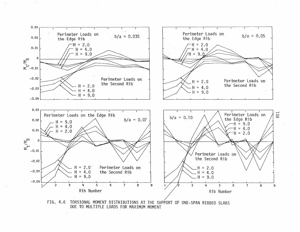
0.03 ~----~----~----~------~~--.------.-----.----~
0.02
0.01
Perimeter Loads on the Edge Rib
H = 2.0 H = 4.0 H= 9.0
b/a = 0.035
CQ 01 :E III ......... } } }
+l :E -0.01
-0.02
H= 2.0 H = 4.0 H = 9.0
Perimeter Loads on the Second Rib
-O.Oij~ ____ ~ ____ ~ ______ ~ ____ ~ ____ ~ ______ ~ ____ ~ ____ ~
CQ :::E
'+.>
0.031~--~----~----~--~----~----~----~--~
0.02
0.01
Perimeter Loads on the Edge Rib H = 9.0 H = .4.0 H = 2.0
/\ b/a = 0.07
o I ~//?C>. ~0, :It:= ----- ~'- ~ .j
:E -0.01
-0.02
H = 2.0· Perimeter Loads on H = 4.0 the Second Rib H = 9.0
2 3 4 5 6 7 8
Rib Number 9
H = 2.0 "'-H = 4.0
H = 9.0
b/a = 0.10
on b/a = 0.05
Perimeter Loads on the Second Rib
J J J
Pe~imeter Loads on the Edge Rib
H = 9.0 H = 4.0 H = 2.0
Perimeter Loads the Second Rib
0-H : 2.0 ,"""-H-4.0
3
H = 9.0
456
Rib Number 7 8
FIG. 4.6 TORSIONAL MOMENT DISTRIBUTIONS AT THE SUPPORT OF ONE-SPAN RIBBED SLABS DUE TO MULTIPLE LOADS FOR MAXIMUM MOMENT
9
w OJ

0.70
0.60
0.50
0.40
(Q
:E 0.30 .......... :E
0.20
0.10
0
0.70
0.60
0.50
0.40
(Q
:E 0.30 ..........
:E
0.20
0.10
0
b/a = 0.035
Perimeter Loads on the Edge Rib
H = 2.0 H = 9.0
H = 2.0 H· =9.0
Perimeter Loads on the Second Rib
I
b/a = 0.07
Perimeter Loads on the Edge Rib
H = 2.0 H = 9.0
Perimeter Loads on the Second Rib
2 345
Rib Number 6 7 8 9
b/a = 0.05
Perimeter Loads on the Edge Rib
H = 2.0 H = 9.0
H = 2.0 H =9.0
Perimeter Loads on the Second Rib
b/a=O.lO
Perimeter Loads on the Edge Rib
H = 2.0 H = 9.0
. Perimeter Loads on the Second Rib 2 3 4 5 6 7
Rib Number
FIG. 4.7 POSITIVE MOMENT DISTRIBUTIONS AT THE 0.44 SPAN LOCATION OF TWO-RIBBED SLABS DUE TO MULTIPLE LOADS FOR MAXIMUM POSITIVE MOMENT
8 9
w
""

0.70
0.60
0.·50
0.40
co ~ 0.30 .......... ~
0.20
0.10
0
0.70
0.60
0.50
n.lI co ~ .......... ~
U • .:JU
0.20
0.10
0
b/a = 0.035
Perimeter Loads on the Edge Rib
H = 2.0 H = 9.0
Perimeter Loads on the Second Rib
b/a ~ 0.07
Perimeter Loads on the Edge Rib H = 9.0 H = 2.0
Perimeter Loads on the Second Rib
2 345 Rib Number
6 7 B 9
b/a = 0.05
Perimeter Loads on the Edge Rib H= 2.0 H = 9.0
Perimeter Loads on the Second Rib
2
b/a= 0.10 on the Edge Rib
Perimeter Loads on the Second Rib 3 456
Rib Number 7
FIG. 4.8 NEGATIVE MOMENT DISTRIBUTIONS AT THE INTERIOR SUPPORT OF TWO-SPAN RIBBED SLABS DUE TO MULTIPLE LOADS FOR MAXIMUM NEGATIVE MOMENT
6 9
+::o

0.10
0.60
0.50
co 0.40 :>-'-... :>-
0.30
.· •• 1 \ 0.20 t-:".: i--j ~ .. ,
0.10
o·
0.10
0.60
0.50
co 0.40 :>-'-... :>-
0.30
0.20
0.10
0
b/a = 0.035
Perimeter Loads on the . Edge Hi b
H = 2.0 H = 9.0
Perimeter Loads ori the Second Rib
"
b/a = 0.07
H = 2.0 H = 9.0
Perimeter Loads on the Edge Rib H = 9.0 H = 2.0
Perimeter Loads on the Second Rib
2 345 Rib Number
15 1
b/a = 0.05
Perimeter Loads on the Edge Rib H = 9.0 H = 2.0-
Perimeter Loads on the Second Rib
b/a = 0.10
Perimeter Loads on the Edge Rib
Perimeter Loads on the Second Rib 8 9 2 3 4 5 6 7
Rib Number
FIG. 4.9 SHEAR DISTRIBUTIONS AT THE EXTERIOR SUPPORT OF TWO-SPAN RIBBED SLABS DUE TO MULTIPLE LOADS FOR MAXIMUM POSITIVE MOMENT
+:0
8 9

,;£00
O.031~------------------~----~----~----~----~----1
0.02
0,01
b/a = 0.035 Perimeter Loads on the Edge Rib
H = 2.0 H = 9.0
o L I I :;0- -====s-,.. ~ ~ ~ 7 I oc::::::::.. ""-
...........
,;£+-3-0.01
-0.02
-0.03
Perimeter Loads on the Second Rib -0.04 LI __ -L __ --L-~_-l-__ __L_ __ _L_ __ ...l__ __ ..J__ _ ____'
0.03 I I I
0.02
0.01
Perimeter Loads on the Edge Rib
H = 2.0 H = 9.0
b/a = 0.07
o I "'~ r;fyz=:--.... ...... \( :;;>"~~" :;tL AI q OJ Cl il~oo ::1 f-1 f-J •. (~ -0 01 f-J. 0 -G c+""" • <l (J") ...... ~ CD f-1 I-i (") !:l:I -0' 02 m' I?:;I CD • f-Jo ~ H~ IT t:?:l O'q (j) '<l. 1-'. I-~
i-:i (D ob::1 m t:l [-b~Q)O
r:-s. I-:l (D H 1-;-1 !...Ao !--I 1=1J h! !:d I~ I-!' ~ 0 J-Io i-:i 0 ::1 oq CJ S
2
H = 2.0 H = 9.0
Perimeter Loads on the Second Rib
'345
Rib Number 6 7 6 9
b/a. = on the Edge Rib
Perimeter Loads on the Second Rib
b/a = 0.10
Perimeter Loads on the Second Rib
345
Rib Number 6 7 8
o m (-I. Id rn P'
~ c+ E3 CD ::1 c+
FIG. 4.10 TORSIONAL MOMENT DISTRIBUTIONS AT THE EXTERIOR SUPPORT OF TWO-SPAN RIBBED SLABS DUE TO MULTIPLE LOADS FOR MAXIMUM POSITIVE MOMENT
9
--' +:a N

0.70
0.60
0.50
0.40 co
:::> '-...
0.30 :::>
0.20
0.10
0
0.70
.0.60
0.50
co 0.40 :::>' '-... :::>
0.30
0.10
o
b/a = 0.035
Perimeter Loads on the Edge Rib
H =2.0 , H = 9.0
Perimeter Loads on the Second Rib
Perimeter Loads on the Second Rib
2 3 'lA 5 6 7
Rib Number 8 9
I.
b/a = 0.05
Perimeter Loads on the Edge Rib H = 2.0 H = 9.0
Perimeter Loads on the Second Rib
b/a=0.10
Perimeter Loads on the Edge Rib H = 2.0 H = 9.0
Perimeter Loads on the Second Rib 2 3 lA 5 6 7
Rib Number
FIG.4.l1 SHEAR DISTRIBUTIONS AT THE 0.95 SPAN LOCATION OF TWO-SPAN RIBBED SLABS DUE TO MULTIPLE LOADS FOR MAXIMUM POSITIVE MOMENT
8 9
-J:::::. W

O.04~. ----~----~----~----~----~----_.----_.--~_.
O.OJ
0.02
0.01
Perimeter Loads on the Edge Rib
H = 2.0 H = 9.0
b/a = 0,,035
co :E ...........
+l :E
o r== \ \ ~"5 ========--:;:;v-z" =1 \ '"
-0.01
-0.02 Perimeter Loads on the Second Rib
-0.031~ ____ ~ ____ ~ ____ ~ ____ ~~ ____ ~ ____ ~ _____ ~ ____ ~
O.04 r• ----.---~.-----~----~--~----~-----------~
0.03
0.02
0.01
co :E
~ :E -0.01
-0.02
Perimeter Loads on the Edge Rib
H = 2.0 H = 9.0
H =2.0 H = 9.0
rre:::7
(
b/a = O.Ol
Perimeter Loads on the Second Rib -0.03 I I I I I I I I
1 2 3 ij 567 8 9
Rib Number
Perimeter Loads on the Edge Rib
2.0 H = 9.0
b/a = 0.05
Perimeter Loads on the Second Rib
Perimeter Loads on the Edge Rib
H = 2.0 H = 9.0
bja = 0.10
Perimeter Loads on the Second Rib
2 3 ij 5 6 7 8
Rib Number
FIG. 4.12 TORSIONAL MOMENT DISTRIBUTIONS AT THE 0.95 SPAN LOCATIONS OF TWO-SPAN RIBBED SLABS DUE TO MULTIPLE LOADS FOR MAXIMUM POSITIVE MOMENT
9
--' +::a +::a

1.40 , '-,
, 1.20
co > ..........
1.00
0.80
> 0.60
0.40
0.20
o
b/a = 0.035
Perimeter Loads on the Edge Rib
~ ----' on the Second Rib
1.40 i '---,
o
b/a = 0.07
Perimeter Loads on the Edge Rib H = 2.0 H = 9.0
Perimeter Loads on the Second Rib 2 3 It 5 6
Rib Number 7 8 9
b/a = 0.05 Perimeter Loads on the Edge Rib
H = 2,.0 H = 9.0
Perimeter Loads on the Second Rib
b/a = 0.10
Perimeter Loads on the Edge Rib
H= 2.D H = 9.0
I.
Perimeter Loads on the Second Rib
2 3 It 5 6 7
Rib Number
FIG. 4.13 SHEAR DISTRIBUTIONS AT THE 0.95 SPAN LOCATION OF TWO~SPAN RIBBED SLABS DUE TO MULTIPLE LOADS FOR MAXIMUM NEGATIVE MOMENT
6 9
,..(::::0 Ul

c::t:I :::E
" +-> ~
c::t:I :::E
" +-> ::E
O.Oll
O.OJ b/a == 0.035
Perimeter Loads on the Edge Rib 0.02 H = 2.0
H = 9.0 0.01
0
-0.01
-0,02 Perimeter Loads on the Second Rib
-0.0'3
O.Olt.~---------------------------------------------------~
0.03 b/a == 0.07 Perimeter Loads on the Edge Rib
H = 2.0 0.02 H = 9.0
0.01
01 ~"'""""" ::::>~:::>7..?-""":--s.""",,,"~
-0.0.1
-0,02 L Peri meter Loads on the Second Ri b
-0.03 I I I I
1 2 3 ij 567 B 9
Rib Number
b/a == 0.05
Perimeter Loads on the Edge Rib H == 2.0 H = 9.0
Perimeter Loads on the Second Rib
b/a = 0.10 Perimeter Loads on the Edge Rib H == 2.0 H == 9.0
Perimeter Loads on the Second Rib
2 ~3 ij 5 . 6 7
Rib Number
FIG. "4.14 TORSIONAL MOMENT DISTRIBUTIONS AT THE 0.95 SPAN LOCATION OF TWO-SPAN RIBBED SLABS DUE TO MULTIPLE LOADS FOR MAXIMUM NEGATIVE MOMENT
8 9
-J:::. m

147
12 I I I I I I
10 - -b/a = 0.10 - -8 t- -
b/a = 0.07 ... -(V) 0
6 ,..- I- b/a = 0.05 .... --'=!!
x b/a = 0.035 - .... ~ 4 - -I-
2
() v
r- 1 I I I , I I I I I
2.0 4.0 6.0 9.0
H
12
10
8 \-\ ::: 9.0
M 0 6 \-\ ::: 2. 0 ,..-
x ~ 4
2
o I I I I I 0.035 0.05 0.07 0.10
b/a
FIG. 4.15 RELATIONSHIPS OF THE MAXIMUM DEFLECTION COEFFICIENT WITH HAND b/a

0.07
0.06 Perimeter Loads on b/a = 0.035 the Edge Rib
2.0 0.05 4.0 Perimeter Loads on
= 9.0 the Second Rib 0.04.
co :E .......... :E+J 0.03
0.02
0.01
0
0.07. I I I
Perimeter Loads on the Edge Rib 0.06 L H = 2.0 b/a = 0.07
H = 4.0 Perimeter Loads on 0.05~ II II _ n n the Second Rib
H:::9.0~
0.04.~~. H = 4.0
~ H=2.0'1' ~
co :E 0.03 ..........
+J :E
0.02
0.01
a ./ /
-I
I I
Perimeter Loads on the Edge Rib
H = 2.0 H = 4.0 H = 9.0
H = 2.0 H = 4.0 H = 9.0
Perimeter Load~ on the Edge Rib ..
H = 2.0 irH = 4.0 rH = 9.0
I- ........ II \ \
b/a = 0.05
Perimeter Loads on the Second Rib
b/a=O.lO
Perimeter Loads on the Second Rib
H =
:3 4. 5 6 7 B 9 /J~
j
~/ Rib ~umber7 8
Rib Number
FIG. 4.16 TORSIONAL MOMENT DISTRIBUTIONS AT THE SUPPORT OF ONE-SPAN RIBBED SLABS DUE TO MULTIPLE LOADS FOR MAXIMUM TORSION
+::0 co
9

0.70
0.60
0.50
0.40
o::l > 0.:10 ............ >
0.20
0.10
a
0.70
0.60
0.50
~ 0.40 ............ >
0.30
0.20
0.10
Perimeter Loads on the Edge Rib
H = 2.0 H = 4.0 H = 9.0
b/a = 0.035
Perimeter Loads on the Second Rib
I I I I
Perimeter Loads on the Edge Rib H ::: 2.0 H = 4.0 H = 9.0
b/a = 0.07 Perimeter Loads on the Second Rib
H = 2.0 H = 4.0 H = 9.0
I I I
Perimeter Loads on the Edge Rib
H = 2.0 H = 4.0 H = 9.0
I ,_
Perimeter Loads on the Edge Rib
H = 2.0 H = 4.0 H = 9.0
I
b/a = 0.05
Perimeter Loads on the Second Rib
= 2.0 = 4.0 = 9.0
b/a = 0.10
Perimeter Loads on the Second Rib
o =---:::;:I 2 ~----~----~--_--L-- ' ~ 345
Rib Number 5· 7 B 9 2 3 4 5 6 7 8 9
Rib Number
FIG. 4.17 SHEAR DISTRIBUTIONS AT THE SUPPORT OF ONE-SPAN RIBBED SLABS DUE TO MULTIPLE LOADS FOR MAXIMUM TORSION
+::\..0

0.07 _ ·1
0.06 L Perimeter Loads on the Edge Rib
0.05 L -H = 2.0 H = 9.0
b/a = 0.035 Perimeter Loads on the Edge Rib
H = 2.0 H = 9.0
b/a = 0.05
Perimeter Loads on ~ 0.04L II the Second Rib
Perimater Loads on the Second Rib
.......... +->
:::E
ro :::E ..........
+-> :::E
0.03~ "-... H = 2.0 H = 9.0
0.02
0.01
0
0.07 I
b/a = 0.07 Perimeter Loads on 0.06 L the Edge Rib
H = 2.0 O.05~ H = 9.0
Perimeter Loads on the Second Rib
H = 2.0 H = 9.0 0.04
0.03
0.02
0.01
0 '345
Rib Number 5 7 B
H = H =
Perimeter Loads on the Edge Rib
H = 2.0 H = 9.0
Rib
b/a = 0.10
Perimeter Loads on the Second Rib H = 2.0 H = 9.0
6 7
FIG. 4.18 TORSIONAL MOMENT DISTRIBUTIONS AT THE EXTERIOR SUPPORT OF TWO-SPAN RIBBED SLABS DUE TO MULTIPLE LOADS FOR MAXIMUM TORSION
U1 o
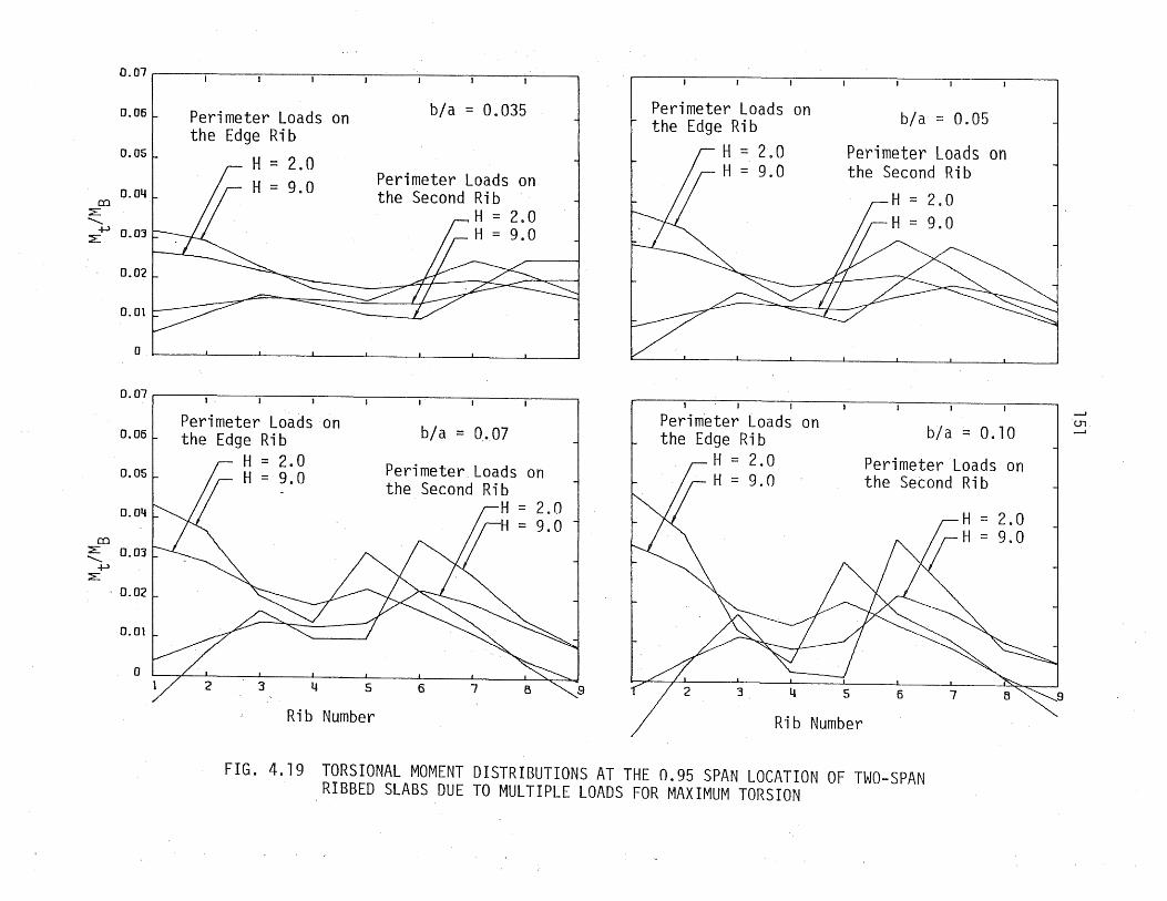
5
Rib Number
b/a = 0.035
Perimeter Loads on the Second Rib
H = 2.0 H = 9.0
b/a = 0.07
Perimeter Loads on the Second Rib
(5
H = 2.0 H = 9.0
Perimeter Loads on the Edge Rib
H = 2.0 H = 9.0
Perimeter Loads on the Edge Rib
H = 2.0 H = 9.0
3
b/a =: 0.05
Perimeter Loads on the Second Rib
= 2.0
b/a == 0.10
Perimeter Loads on the Second Rib
f5 7
= 2.0 9.0
Rib Number
FIG. 4.19 TORSIONAL MOMENT DISTRIBUTIONS AT THE 0.95 SPAN LOCATION OF TWO-SPAN RIBBED SLABS DUE TO MULTIPLE LOADS FOR MAXIMUM TORSION
U1 ........
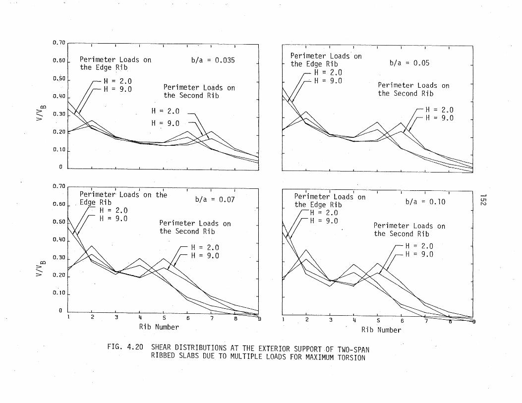
Perimeter Loads on the Edge Rib
H :: 2.0 H = 9.0
I I I
Perimeter Loads on the Edge Rib
H = 2.0 H = 9.0
b/a = 0.05
Perimeter Loads on the Second Rib
b/a = 0.10
Perimeter Loads on the Second Rib
2 3 456
Rib Number
FIG. 4~20 SHEAR DISTRIBUTIONS AT THE EXTERIOR SUPPORT OF TWO-SPAN RIBBED SLABS DUE TO MULTIPLE LOADS FOR MAXIMUM TORSION
--I
U1 N

co > .......... >
co > .......... >
O.70~, ----~----~----~~----~----._----._----_.----~
Perimeter Loads on 0.60 L the Edge Ri b
H 2.0 0.50 1\ / / H = 9.0
0.40
0.30
0.20
0.10 H = 2.0 H = 9.0
b/a = 0.035
Perimeter Loads on the Second Rib 0
0.70
on b/a = 0.07 0.60 Perimeter Loads on
the Second Rib 0.50
0.1!0
0.30
0.20
0.10
0 2 '3 456
Rib Number
H = 2.0 H = 9.0
7 8 9
Per~mete~ Loads' on the Edge Rib
H = 2.0 H = 9.0
H = 2.0 H = 9.0
b/a = 0.05
Perimeter Loads on the Second Rib
, on b/a = 0.10
Perimeter Loads on the Second Rib
2 3 456
Rlb Number
H = 2.0 H = 9.0
7 8
FIG. 4.21 SHEAR DISTRIBUTIONS AT THE 0.95 SPAN LOCATION OF TWO-SPAN RIBBED SLABS DUE TO MULTIPLE LOADS FOR MAXIMUM TORSION
9
--I
<.n w

b/a = 0.05
Perimeter Loads on the Edge Rib
b/a = 0.10
Perimeter Loads on the Edge Rib
2
H = 2.0 H = 9.0
3 l! ,5
Perimeter Loads on the Second Rib
H = 2.0 H = 9.0
Perimeter Loads on the Second Rib
6 7 8
Rib Number
FIG. 4.22 NEGATIVE MOMENT DISTRIBUTIONS AT THE INTERIOR SUPPORT OF TWO-SPAN RIBBED SLABS DUE TO MULTIPLE LOADS FOR MAXIMUM TORSION
9
Ul ..p,.

0.70
0.60
0.50
o:::l :::E 0.40 -.........
x I'd E 0.30 :::E
0.20
0.10
0
0.70
0.60
0.50
o:::l 0.40 >---...:..
>< rtS E 0.30 >-
0.20
0.1: r ,
0.07
0.06
0.05
0.04 co
:E -... +-'
:E 0.03
0.02
0.01
0 0.035
155
Maximum r~oment
Accompanying Torsion
L H = 9.0 H = 6.0
O ---H -::: 9.:-_---- 0 --_--u -::: 6. _--_--e-- r\_~-O ..._.--- --u - £\.. ---_--- .-...-- fI""':_------- --- --_- _-.e---'-- _--e---
..."....... ."."......,.".,.-.."""- ~--------------- ----- H = 2.0 ----...-.------_--e---------------- H = 9.0
0.05
H = 6.0 H = 4.0
H = 2.0
b/a 0.07
Perimeter Loads on the Edge Rib Perimeter Loads on the Second Rib
0.1:0
FIG. 4.23 RELATIONSHIPS OF MAXIMUM MOMENT, MAXIMUM SHEAR AND THE ACCOMPANYING TORSION, WITH HAND b/a FOR 'ONE-SPAN RIBBED SLABS UNDER MULTIPLE LOADS FOR MAXIMUM MOMENT

0.07
0.06
0.05
0.04 . c::c
::E --.......
156
Maximum TOrsion H ::: 9.0 ------fi==6...JL ---.......------ ---------.----- ------- --- --- --- -- ---___ --- -- ---- -- ___ ~ --------__ ---------11= 4. 0
~ --- --- --- ----- ----- -- --- ---- -- -- 2 0 ---....--e-- _--- . H == . ---- --...-.-- ----- -- -- - ---.------H-- 9 0 ,.,."...-::::.,..,.."...."""""- ------------ - . -- --e------- H == 4.0
~ 0.03 H == 2.0 E +>
::E
co ::> --....... >
0.02
0.01
0
0.70
0.60 Accompanying Shear
0.50
0.40
0.30
'---;#~-::::::~:~H=r9 a Wii[! .....-:::-:::::::::=:::::::-.-.---- • --:::::: ::;::::..;,..--...- H == 6 0 ...---:::;::::::' ..- .
;,..--;:...-"'- H ::: 4.0 H = 2. r;H == 9.0
H ::: 4.0 ::: 2.0
0.20
0.10
O~~ ______ ~ ______ ~ ______ ~ __ ~ __ ~ ____ ~~ ____ ~ 0.035 0.05 0.07
- - Perimeter Loads on the Edge Ri b -- Perimeter Loads on the Second Ri b
FIG. 4.24 RELATIONS OF MAXIMUM TORSIONAL MOMENT AND THE .. ACCOMPANYING SHEAR WITH HAND b/a FOR ONE-SPAN
RIBBED SLABS UNDER MULTIPLE LOADS FOR MAXIMUM TORSION
0.10

co :::E ............
>< ro E
:::E
co :::E ............
-I-l :::E
157 0.60
0.50 Maximum Positive Moment H = 9.0
0.40 ---___ -------H=-2.o
-----=-~-----H-::-9-0----- -- --~ --- . -- ---------- ----- H = 2.0 0.2
o ~~ ______ -L ______ ~ ____ ~~ ____ ~~ ____ ~ ____ ~
0.60----------~------------~~----~------~----~
0
0.06
0.05
0.04
0.03 .
0.02
0.01
0 0.035
H = 9.0 _-e----------__ --- H-20--Maximum Shear
_-- ___e_-- -. ............. --------- ----------.""..... ---------- .-.--- H == 9.0
H == 2.0
Accompanying Torsion U :: 9.0 _----n _-
----------------.-
-------------H :: 2.0 -----------------~-__ ---e-----
-------- ----- --- --- -- -----
o .05 b/a
0.07
H = 9.0 H = 2.0
Perimeter Loads on the Edge Rib Perimeter Loads on the Second Rib
n.10
FIG. 4.25 RELATIONSHIPS OF MAXIMUM POSITIVE MOMENT AT THE 0.44 SPAN LOCATION, MAXIMUM SHEAR AND THE ACCOMPANYING TORSION AT THE EXTERIOR SUPPORT WITH HAND b/a FOR TWO-SPAN RIBBED SLABS UNDER MULTIPLE LOADS FOR MAXIMUM POSITIVE MOMENT

co >--....
x n::s E
>-
158 0.80
0.70
0.60
,,------ H Maximum Shear ~-- ---:::: 9 0 ,,-"'- -- .
.,.-"'- ---~ ,,-~- H --.........- .,.-"'- --- :::: 2 0 .,.----- ~~.,.- --~-
~ -~ ----- ----------.,.-.-"
0.3
0.20
0.10
0
0.50 J J • J J I I
0.40 r- Accompanying Moment -
H = 9.0 O 30 _--------4P . - _-----+-----Tr = 2.0 --...---- -----------------~~ O 20~---=-==-.- ----- H = 9.0
. ii=---- - -----=::::::::1= H 2 . 0
0.10~
o
0.05
0.041-
r
I
-
I I
I I
Accompanying Torsion
-
I I I
I I I
gO _---4 \-\ ::: -:..----- -
....... -----....... ---~ 0.03r- _- ....... ---- -
. --~~- -H- = 2.0 ---~ ---0.02_ _--------e-------- -~~------.-
0.01 - -r H = 9.0 Ir H - 2•O
ot;;;;:::::::~::~Jt::dI~;;~~~~==~====~:~I~==~ 0.035 0.05 0.07 0.10
b/a - - Perimeter Loads on the Edge Ri b -- Perimeter Loads on the Second Ri b
FIG. 4.26 RELATIONSHIPS OF MAXIMUM SHEAR AND THE ACCOMPANYING TORSION AT THE 0.95 SPAN LOCATION AND NEGATIVE MOMENT AT THE INTERIOR SUPPORT WITH HAND bla FOR TWO-SPAN RIBBED SLABS UNDER MULTIPLE LOADS FOR MAXIMUM POSITIVE MOMENT

o:::l L ............
X ~ E
L
o:::l > ............
x ~ E
>-
0.70
0.60
0.50
0.40
0.30
0.20
O~ 1 0
0 1 .10
1 .00
0.90
0.80
0.70
0.60
0.50
0.40
0.30 0.04
O. 03 ~
159
Maximum Negative Moment H = 9.0 _----- -- --- -- --.-8------ 0 _---- H~3~-----_~- _--0------
----- ---- H = 9 0 ...- ~- . --__ ---~ H = 2.0
Maximum Shear ...-......e-.~_ 1-1
...-"'- --L.L...,:::: 00 ...- -~ ...- --~~ --~ ~.. --"..,....~ ~ ---- H :::: 2 0 ,.,..,.....- ~...-. ---~
-...-~...- ----~...- ---~-- ... --,.,..,../ // ,.,..,..
I I I I I I
H = 9.0 _-----..:aI ....e--------Accompanying Torsion
...._e___-.....:....------o. 02 F-~---- -
H = 2.0 ___ u . . _._------- - ---------
-0.01 ~-----...--- H = 9.0
0~~====~~-~~~;;;;;;;;;:~~~::::~H:=~2~.0~:J II"""
0.035 0.05 0.07 b/a
Perimeter Loads on the Edge Rib Perimeter Loads on the Second Rib
0.10
FIG. 4.27 RELATIONSHIPS OF MAXIMUM NEGATIVE MOMENT AT THE INTERIOR SUPPORT, MAXIMUM SHEAR AND THE ACCOMPANYING TORSION OF THE 0.95 SPAN LOCATION WITH HAND b/a FOR TWO-SPAN RIBBED SLABS UNDER MULTIPLE LOADS FOR MAXIMUM TORSION

0.07
0.06
0.05 CQ
::E ........ >< 0.04
rt:S E
+-> 0.03 ::E
0.02
0.01
0
0.70
0.60
0.50
0.40 CQ
> ........ > 0.30
0.20
0.10
0 0.035
160
Maximum Torsion at the Exterior Support
H ::: 9.0 ---...---------------....... -- --- --- --- ----------.---------- H - 2.0 __ ;... ...... ----------
-------------- - 9 0 ..... ---..------....... - .
H = 2.0
Accompanying Shear H = 9.0
-~------------------ H = 2.0 ------- ---------------------- -----
------ -------- --------
0.05 0.07
b/a
Perimeter Loads on the Edge Rib Perimeter Loads on the Second Rib
H = 9.0
H = 2.0
0.10
FIG. 4.28 RELATIONSHIPS OF MAXIMUM TORSIONAL MOMENT AND THE ACCOMPANYING SHEAR AT THE EXTERIOR SUPPORT WITH HAND b/a FOR TWO-SPAN RIBBED SLABS UNDER MULTIPLE LOADS FOR MAXIMUM TORSION ,

c:::c ~ ...........
x ro E
+J ~
c:::c :> ........... :>
c:::c :E: ........... ~
0.06
0.05
0.04
0.03
0.02
0.01
O.
0.80
0.70
0.60
161
Maximum Torsion at the 0.95 Span Location
------------- ...... ---H = 9.0 __ _ ----------------H = 9.0
_~ __ ~r---------~-----H~2~---
H = 2.0
Accompanying Shear ----- H - 9 ............. -------- - 0 ."".......-......- --------:...... ,........-- ----
,.... ------ H -.......- -- --- =: 2 0 ~ -,.... -- .
~~,....-- ----~ -- --~ ,....- -
~ ~
0.50
0.40
0.30
0.20
0.10
0
0.40
0.30
-...-,.-"'-
H = 9.0
H = 2.0
H = 9.0
AccompanYi: T:Si:._---.:::=_=__=_ H = 2.0 ~-=-=== 0.20 --- --- --- --- ------ - -- --- --~. -4------,--==:=1 --. _---e-.--
--- ____ --__ ------- / I --.
0.10
o 0.035 0.05
b/a 0.07
H = 9.0 H = 2.0
Perimeter Loads on the Edge Rib Perimeter Loads on the Second Rib
0.10
FIG. 4.29 RELATIONSHIPS OF MAXIMUM TORSIONAL MOMENT AND THE ACCOMPANYING SHEAR AT THE 0.95 SPAN LOCATION AND NEGATIVE MOMENT AT THE INTERIOR SUPPORT WITH HAND bia FOR TWO-SPAN RIBBED SLABS UNDER MULTIPLE LOADS FOR MAXIMUM TORSION

162.
Multiple Loads for Maximum Moment
Regular Edge· Rib
Stiffer Edge Rib
---..::::. :::: :::: :::: = = ..... - -----
Multiple Loads for Maximum Shear
Regular Edge Rib
tiffer Edge Rib
Multiple Loads for Maximum Torsion
Regular Edge Rib
Stiffer Edge Rib
0.02 ------ --- ---..."...,.. ........ ~.-- - -........-:~~,.... ,,-- .
o ~~~----------------------~--------------~ .,.,/
-0. 02 L--_---L __ -I...-__ ..l-_---' __ --L-__ -:-'---"'-------'
'1' 2 3 4 5 6 8 9 Rib Number
Perimeter Loads on the Edge Rib Perimeter Loads on the Second Rib
FIG. 4.30 EFFECTS OF THE STIFFENED EDGE RIB ON MOMENT, SHEAR AND TORSIONAL MOMENT.DUE TO MULTIPLE LOADS

163 O~60~--~----~----~----~----.----.-----r--~
0.50 Moment at Midspan
0.40
co 0.30
Regular Edge Rib Stiffer Edge Rib
::E --------------------------- --------- ------ - -----~------ ---------------- ----- ---------- --------
::E 0.20
co > ........... >
co ::E: ...........
0.10
oL-~~~ __ ~ __ ~ __ ~~~~~ __ ~ 0.70
-O.DO Shear at Support
0.5e)
0.40
0.30
0.20
0·'00 t O. 14
O. 12
0.10
0.08
Regular Edge Rib
Stiffer Edge Rib
Torsion at Support
j
';E+J 0.06
Regular Edge Rib
Stiffer Edge Rib
0.04
0.02.
o ~--~~--~----~--~~--~~--~----7_--~ 1 9
FIG. 4.31 EFFECTS OF THE STIFFENED EDGE RIB ON MOMENT, SHEAR, AND TORSIONAL MOMENT DUE TO A LINE LOAD ON THE EDGE RIB

co :::E: ......... :::E:
co >-......... >-
co :::E: .........
+-> :E:
FIG. 4.32
164 1.60~--~--~~----~----~----~--~-----.----~
1.20
1 .00
0.80
0.60
0.40
0.20
0
1.40
1.00
0.80
0.60
0.40
0.20
0
0.05
0.04
0.03
0.02
0.01
0 1
MOMENTS,
Moment at Midspan
Regul ar Edge Ri b Stiffer Edge Rib
.... ---........ --................... -.. . .... - .................. - ........................... - ...................... ·············.··-··.--·-······.··--.-1.-···.·.···.···-.- .-.- --•. ----... .
Shear at Support
Regular Edge Rib Stiffer Edge Rib
Torsionat Support
Regular Edge Rib
Stiffer Edge Rib
4 5 Rib Number
SHEARS, AND TORSIONS DUE TO A MIDSPAN LINE LOAD
9