Embed Size (px)
Citation preview
Rhoban Hardware and Software Open Source Contributionsfor RoboCup Humanoids
Quentin Rouxel, Grégoire Passault, Ludovic Hofer, Steve N’Guyen, Olivier Ly
Abstract— Three newly released hardware and software opensource contributions are presented. The first one is a newmechanical and electronics design for low cost stain gauge basedfoot pressure sensors. The second is a lightweight user interfacelibrary dedicated to robotics applications and allowing for an“on the fly” interaction with an on board program. The thirdone is an implementation of an open loop walk generator forhumanoid robots based on splines and inverse kinematics.
I. INTRODUCTION
The Robocup soccer Humanoid league is a highly com-petitive challenge with a regular increasing difficulty. The2015 update of the rules included an artificial grass field,a white ball and white goals. These new problems make itquite difficult for new teams to enter the competition fromscratch. Moreover, the willingness to create collaborativeteams emphasizes the need for open platforms. In thiscontext, this work presents three open source contributionsfrom the Rhoban team (Humanoid kid size) to the Robocupcommunity. These three projects are presented in the follow-ing sections and are entirely independent on each other.
II. LOW COST FOOT PRESSURE
The locomotion is one of the biggest challenge of hu-manoid robotics, and especially with the RoboCup humanoidleague constraints that only allow sensors and actuators thatare comparable with humans.
Typically, for walking, shooting or balancing, one can ask:
• Where is the center of pressure of the robot?• Which foot is actually touching the ground and support-
ing the robot?• Is the robot standing on the ground, or falling?
All these questions can be estimated using IMU (ac-celerometer, gyroscope), the position of the motors and acomplete model of the robot. However, sensing the forceapplied by the robot on the floor, and thus on the tips of thefeet, brings new information.
Human-size recent robots, such as TORO [1] feature6DOF industrial force sensors in each foot, which are veryhigh quality but also very expansive measurement instru-ments. This is why we decided to produce a custom designthat would be both affordable and suitable for small to mid-size humanoids [2].
The authors are with the Rhoban team, LaBRI, Univer-sity of Bordeaux, France. Emails: {quentin.rouxel,gregoire.passault, ludovic.hofer,steve.nguyen, olivier.ly}@labri.fr
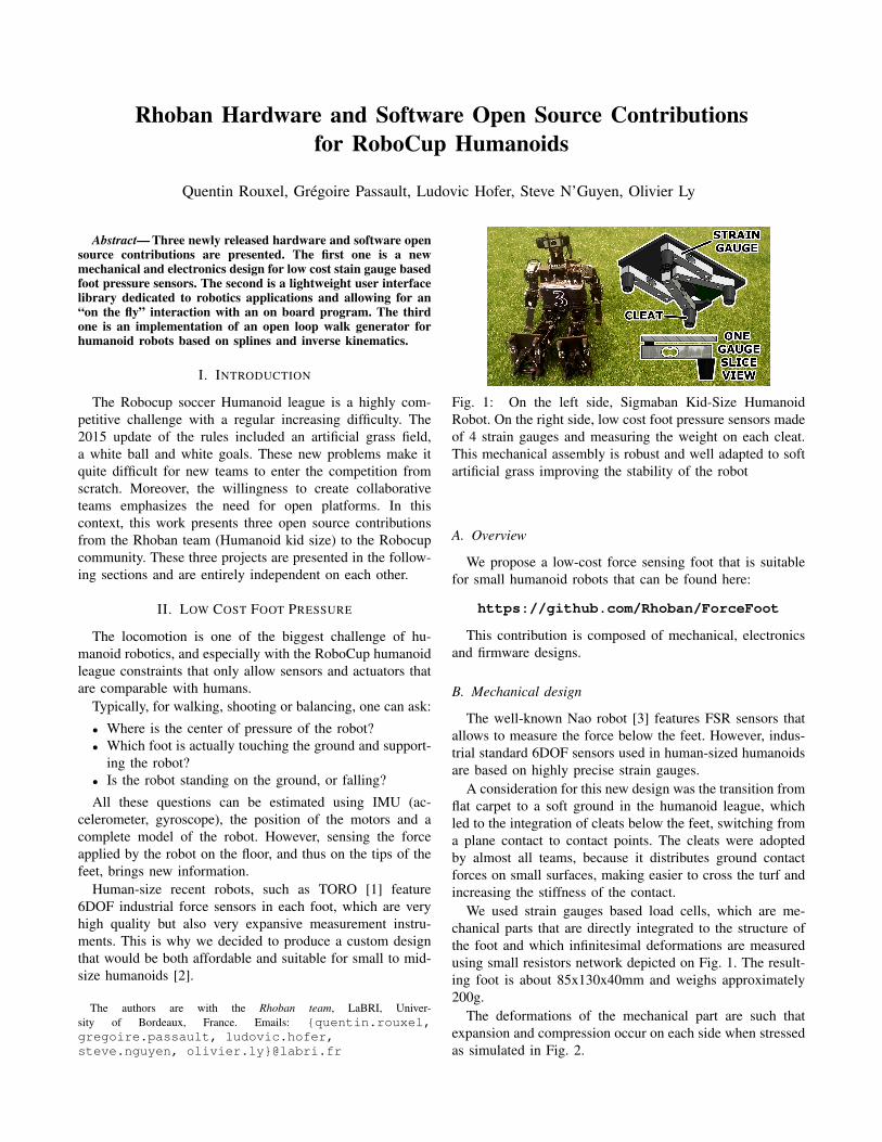
Fig. 1: On the left side, Sigmaban Kid-Size HumanoidRobot. On the right side, low cost foot pressure sensors madeof 4 strain gauges and measuring the weight on each cleat.This mechanical assembly is robust and well adapted to softartificial grass improving the stability of the robot
A. Overview
We propose a low-cost force sensing foot that is suitablefor small humanoid robots that can be found here:
https://github.com/Rhoban/ForceFoot
This contribution is composed of mechanical, electronicsand firmware designs.
B. Mechanical design
The well-known Nao robot [3] features FSR sensors thatallows to measure the force below the feet. However, indus-trial standard 6DOF sensors used in human-sized humanoidsare based on highly precise strain gauges.
A consideration for this new design was the transition fromflat carpet to a soft ground in the humanoid league, whichled to the integration of cleats below the feet, switching froma plane contact to contact points. The cleats were adoptedby almost all teams, because it distributes ground contactforces on small surfaces, making easier to cross the turf andincreasing the stiffness of the contact.
We used strain gauges based load cells, which are me-chanical parts that are directly integrated to the structure ofthe foot and which infinitesimal deformations are measuredusing small resistors network depicted on Fig. 1. The result-ing foot is about 85x130x40mm and weighs approximately200g.
The deformations of the mechanical part are such thatexpansion and compression occur on each side when stressedas simulated in Fig. 2.
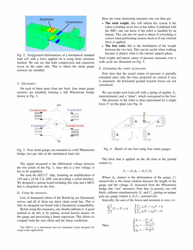
Fig. 2: Exaggerated deformations of a mechanical standardload cell with a force applied on it using finite elementsmethod. We can see that both compression and expansionoccur on the same side. This is where the strain gaugeresistors are installed.
C. Electronics
On each of these parts (four per foot), four strain gaugeresistors are installed, forming a full Wheatstone bridgeshown in Fig. 3.
Fig. 3: Four strain gauges are mounted as a full Wheatstonebridge, two per side of the mechanical load cell.
The signal measured is the differential voltage betweenthe two points of the Fig. 3, since this is a low voltage, ithas to be amplified.
We used the HX7111 chip, featuring an amplification of128 and a 24 bit Σ∆ ADC and providing a serial interface.We designed a custom board including this chip and a MCUthat is integrated on the foot.
D. Using the measures
Lots of humanoid robots of the RoboCup use Dynamixelservos, and all of them use daisy chain serial bus. This iswhy we designed our board with a Dynamixel compatibility.
Before using this measures, one should calibrate it. A goodmethod to do this is by putting several known masses onthe gauge and processing a linear regression. This allows tocompute both the zero offset and the linear coefficient.
1The HX711 is a mainstream low-cost integrated circuit designed forweigh scales applications
Here are some interesting measures one can then get:• The total weight: this will inform the system if the
robot is holding on its feet or has fallen. Combined withthe IMU, one can know if the robot is handled by anhuman. This can also be used to detect if everything iscorrect when performing system check or if any externalforce is applied.
• The foot ratio: this is the distribution of the weightbetween the two feet. This can be useful when walkingbecause it depicts what is the current support phase.
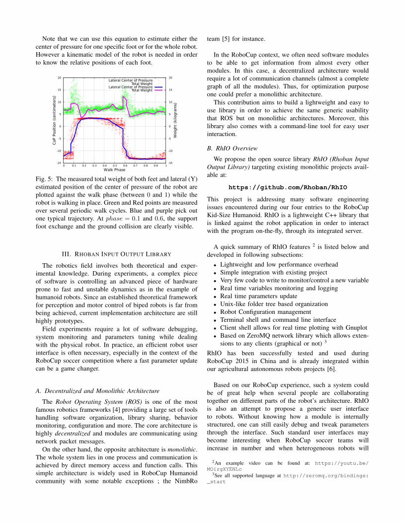
Total weight and lateral center of pressure measures over awalk cycle are illustrated on Fig. 5.
E. Estimating the center of pressure
Note here that the actual center of pressure is partiallyestimated since only the force projected on vertical Z axisis measured. All horizontal ground reaction forces are notconsidered.
We can model each load cell with a spring of rigidity Ki
(newton/meter) and a “plate”, which correspond to the foot.The pressure of the robot is then represented by a single
force P on this plate (see Fig. 4).
Fig. 4: Model of one foot using four strain gauges.
The force that is applied on the ith cleat at the groundcontact is:
Fi = Ki∆i = KiCiRi
Where ∆i (meter) is the deformation of the gauge, Ci
(meter/volt) is the linear relation between the length of thegauge and the voltage Ri measured from the Wheatstonebridge (the “raw” measure). Note that, in general, one willlikely calibrate simultaneously Ki and Ci, getting an uniquegain per gauge (which is KiCi, newton/volt).
Statically, the sum of the forces and moments is zero, i.e.:i=4∑i=1
Fi + P = 0
{∑i xiFi + xpP = 0∑i yiFi + ypP = 0
Thus:
P = −
∑i Fi
xp = −∑
i xiFi
P
yp = −∑
i yiFi
P
Note that we can use this equation to estimate either thecenter of pressure for one specific foot or for the whole robot.However a kinematic model of the robot is needed in orderto know the relative positions of each foot.
-15
-10
-5
0
5
10
15
20
0 0.1 0.2 0.3 0.4 0.5 0.6 0.7 0.8 0.9 1-15
-10
-5
0
5
10
15
20
CoP
Posit
ion
(cen
timet
ers)
Wei
ght (
kilo
gram
s)Walk Phase
Lateral Center of PressureTotal Weight
Lateral Center of PressureTotal Weight
Fig. 5: The measured total weight of both feet and lateral (Y)estimated position of the center of pressure of the robot areplotted against the walk phase (between 0 and 1) while therobot is walking in place. Green and Red points are measuredover several periodic walk cycles. Blue and purple pick outone typical trajectory. At phase = 0.1 and 0.6, the supportfoot exchange and the ground collision are clearly visible.
III. RHOBAN INPUT OUTPUT LIBRARY
The robotics field involves both theoretical and exper-imental knowledge. During experiments, a complex pieceof software is controlling an advanced piece of hardwareprone to fast and unstable dynamics as in the example ofhumanoid robots. Since an established theoretical frameworkfor perception and motor control of biped robots is far frombeing achieved, current implementation architecture are stillhighly prototypes.
Field experiments require a lot of software debugging,system monitoring and parameters tuning while dealingwith the physical robot. In practice, an efficient robot userinterface is often necessary, especially in the context of theRoboCup soccer competition where a fast parameter updatecan be a game changer.
A. Decentralized and Monolithic Architecture
The Robot Operating System (ROS) is one of the mostfamous robotics frameworks [4] providing a large set of toolshandling software organization, library sharing, behaviormonitoring, configuration and more. The core architecture ishighly decentralized and modules are communicating usingnetwork packet messages.
On the other hand, the opposite architecture is monolithic.The whole system lies in one process and communication isachieved by direct memory access and function calls. Thissimple architecture is widely used in RoboCup Humanoidcommunity with some notable exceptions ; the NimbRo
team [5] for instance.
In the RoboCup context, we often need software modulesto be able to get information from almost every othermodules. In this case, a decentralized architecture wouldrequire a lot of communication channels (almost a completegraph of all the modules). Thus, for optimization purposeone could prefer a monolithic architecture.
This contribution aims to build a lightweight and easy touse library in order to achieve the same generic usabilitythat ROS but on monolithic architectures. Moreover, thislibrary also comes with a command-line tool for easy userinteraction.
B. RhIO Overview
We propose the open source library RhIO (Rhoban InputOutput Library) targeting existing monolithic projects avail-able at:
https://github.com/Rhoban/RhIO
This project is addressing many software engineeringissues encountered during our four entries to the RoboCupKid-Size Humanoid. RhIO is a lightweight C++ library thatis linked against the robot application in order to interactwith the program on-the-fly, through its integrated server.
A quick summary of RhIO features 2 is listed below anddeveloped in following subsections:
• Lightweight and low performance overhead• Simple integration with existing project• Very few code to write to monitor/control a new variable• Real time variables monitoring and logging• Real time parameters update• Unix-like folder tree based organization• Robot Configuration management• Terminal shell and command line interface• Client shell allows for real time plotting with Gnuplot• Based on ZeroMQ network library which allows exten-
sions to any clients (graphical or not) 3
RhIO has been successfully tested and used duringRoboCup 2015 in China and is already integrated withinour agricultural autonomous robots projects [6].
Based on our RoboCup experience, such a system couldbe of great help when several people are collaboratingtogether on different parts of the robot’s architecture. RhIOis also an attempt to propose a generic user interfaceto robots. Without knowing how a module is internallystructured, one can still easily debug and tweak parametersthrough the interface. Such standard user interfaces maybecome interesting when RoboCup soccer teams willincrease in number and when heterogeneous robots will
2An example video can be found at: https://youtu.be/MOizgXYENLc
3See all supported language at http://zeromq.org/bindings:_start
play in the same team.
The RhIO library is divided into two major componentsas shows in Fig. 8. On the robot’s side, the server is runningthe monolithic application. On user’s side, one or manyclients are connected to the server through TCP protocol(based on standard ZeroMQ4 network library) for userinteraction.
C. Server Side
Embedded onRobot's Computer
Users Side
Monolithic Main Application
RhIO Client
RhIO Server
ZeroMQ (Network Library)
Module
ZeroMQ (Network Library)
Module
Module
Module
Parameters and configuration manager
RhIO ShellMonitoring, Tunning, Plotting
RhIO Client
ZeroMQ (Network Library)RhIO ShellMonitoring, Tunning, Plotting
RhIO Architecture
Fig. 6: RhIO Client-Server architectureRhIO Root:-vision/-pressure/-sensors/-teamplay/-moves/
-approach/-robocup/-standup/-walk/
footYOffset float 0.025freq float 1.7supportPhaseRatio float 0trunkRoll float 0trunkYOffset float 0trunkZOffset float 0.02[...]
[...]-servos/
-head_pitch/readingErrors int 18angle float 69.7852speed float 0temperature float 36torque float 0.966764voltage float 16.3[...]
-head_yaw/-left_ankle_pitch/-left_ankle_roll/-left_elbow/
Fig. 7: Example of RhIO root node showing our internalsoftware structure at RoboCup 2015 (Humanoid Kid-SizeLeague). Our main modules are displayed at root level andsome sub nodes show how values can be used to monitormotor state and configure the walk engine
RhIO allows for the creation of 3 kind of global objectson the server side. These objects can then be accessedeverywhere within the robot’s application:
• Values (of 4 basic types5) used for monitoring or asconfiguration parameters. Values have meta parameters
4http://zeromq.org/5Types are either boolean, integer, floating number or string
such as their name, an optional comment, optional min-imum and maximum range along with a flag indicatingif the value is temporary or if it will to be persisted onthe disk when the configuration is saved.
• Functions used by the client to call custom functions onthe robot side, with optional arguments. They are usedto trigger special actions or display monitoring reportfrom the robot.
• Output stream allows for displaying textual informationon a specific channel. Its primary use is for debuggingand acts as a remote logging output.
Each of the previous object is attached to a Node belong-ing to a virtual hierarchy tree. In practice, each root noderepresent a system module (as motion, vision, sensors, . . . ).A tree example is partially displayed at Fig. 7.It is then possible to easily interact with this representationwith a command line tools mimicking a UNIX shell.
More complete documentation is available on the projectwebpage 6.
D. Client Side
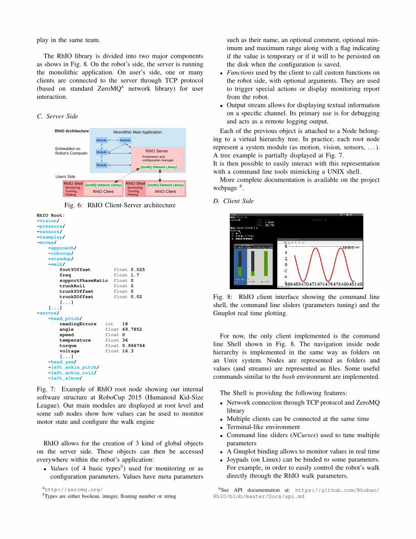
Fig. 8: RhIO client interface showing the command lineshell, the command line sliders (parameters tuning) and theGnuplot real time plotting.
For now, the only client implemented is the commandline Shell shown in Fig. 8. The navigation inside nodehierarchy is implemented in the same way as folders onan Unix system. Nodes are represented as folders andvalues (and streams) are represented as files. Some usefulcommands similar to the bash environment are implemented.
The Shell is providing the following features:• Network connection through TCP protocol and ZeroMQ
library• Multiple clients can be connected at the same time• Terminal-like environment• Command line sliders (NCurses) used to tune multiple
parameters• A Gnuplot binding allows to monitor values in real time• Joypads (on Linux) can be binded to some parameters.
For example, in order to easily control the robot’s walkdirectly through the RhIO walk parameters.
6See API documentation at: https://github.com/Rhoban/RhIO/blob/master/Docs/api.md

• The client library is implemented in C++. Writing a newclient in the same language would be quick and easy.
E. Future Work
At the current state, the library lacks a support for animage type. This particular kind of communication would bevery useful since monitoring vision processing is of primaryimportance. Both server side and proper client side tools areneeded to efficiently monitor the vision module ; debuggingtagged images does not need to be computed when notmonitored. In addition, a graphical client (could be web-based) might be convenient.
IV. OPEN LOOP WALK ENGINE
X (forward)
Y (lateral)
Z (height)
roll
pitch
yaw
Ank
l e to
gr
oun
d 1
Head (pitch/yaw)
Elbow
Shoulder (pitch/roll))
Hip (yaw/pitch/roll)
Knee
Ankle (pitch/roll))
Kne
e t o
an k
le
Hi p
to k
nee
Feet lateral distance
Trunk reference frame
Fig. 9: Kinematic model and reference frame of the hu-manoid. 20 degrees of freedom, 6 per leg.
Biped walk is an extensively studied problem and variousapproaches have been tried to address it, from classic auto-matic control and the well known ZMP, bio-inspiration andCPG to machine learning.
The theoretical problem is quite difficult, involvingcomplex kinematic structures, high dimensional control,dynamics motion and changing ground contact withcollisions. However in practice, acceptable stable andomnidirectional walk engine can be achieved in a rathersimple way on small humanoid robots along with goodmechanical design and some expert manual parameterstuning. The walk engine that we propose here is sharingsimilar ideas that were first exposed by Behnke [7].
Periodic splines generate the main oscillatory pattern usedto define feet and trunk cartesian parametrized trajectories.Motor target positions are then computed through "standard"inverse kinematics.
The library IKWalk that we propose is a C++ implemen-tation of a typical fully open loop walk engine for humanoid
robots. This implementation was used on artificial grass bythe Rhoban Football Club during the soccer competitionRobocup Kid-Size 2015 in China. The only software de-pendency needed is the Eigen linear algebra library 7.
https://github.com/Rhoban/IKWalk
A. Walk Engine Overview
The implemented engine is only considering the 12degrees of freedom of the legs. Fig. 9 shows the “standard”small humanoid model design. Conveniently aligned 6degrees of freedom per leg allow for a quite simpleanalytic inverse kinematics. The center of the knee axis, theintersection of the three rotation axes of the hip and theintersection of the two rotation axes of the ankle are allaligned on a vertical line.
This model is defined by 4 geometrical parameters: thedistances between
• the center of hip axes and knee axis• the knee axis and the center of ankle axes• the center of ankle axes and the ground• the two feet
-1
-0.5
0
0.5
1
0 0.1 0.2 0.3 0.4 0.5 0.6 0.7 0.8 0.9 1
Norm
aliz
ed s
plin
e
Phase
Step splineSwing spline
Rise splineTurn spline
-1
-0.5
0
0.5
1
1.5
0 2 4 6 8 10 12
Mot
or ta
rget
pos
ition
s (r
adia
n)
Time (seconds)
left hip yawleft hip pitch
left hip rollleft knee
left ankle pitchleft ankle roll
Fig. 10: (Left) The four periodic spline patterns usingexample parameters. The walk is only in single supportphase.
Fig. 11: (Right) Computed target positions for the left legwith example parameters. Between t = 0...2 and t = 10...12,the walk is stopped. Between t = 2...4, the robot walks inplace. Between t = 4...6, the walk is going forward. Betweent = 6...8, the robot is walking on the left with lateral steps.And between t = 8...10, the robot is turning on its right.
The four splines patterns depicted in Fig. 10 are used togenerate the whole motion in Cartesian space. The walk cyclebegins at phase = 0 when the left foot just lands and startsgoing backward. At phase = 0.5, the right foot lands andthe left foot takes off and goes forward when the doublesupport phase length is set to zero.
• Step spline: Forward and lateral footstep displacements(X and Y axes) with respect to the trunk. Note thatat phase = 1, the left foot is landing with non zerobackward velocity.
• Rise spline: Foot motion in Z axis
7C++ header library available at: http://eigen.tuxfamily.org/index.php?title=Main_Page
• Turn spline: Foot yaw rotation used for robot’s turning• Swing spline: Lateral (Y) oscillation of the trunk with
respect to the feet used to move the center of masstoward the supporting foot.
These normalized splines are then scaled and phase shiftedto build the actual foot target positions (X,Y,Z) and orienta-tions and fed to the inverse kinematics.
B. Engine Parameters
The walk engine uses the following main parameters 8:• Frequency of the complete walk cycle (two steps)• Ratio between single support only to full double support• Foot rise height (Z) during flying phase• Trunk height (Z) from the ground• Lateral (Y) distance offset between the two feet• Amplitude of lateral (Y) swing oscillations• Lateral swing phase shift with respect to the foot rise
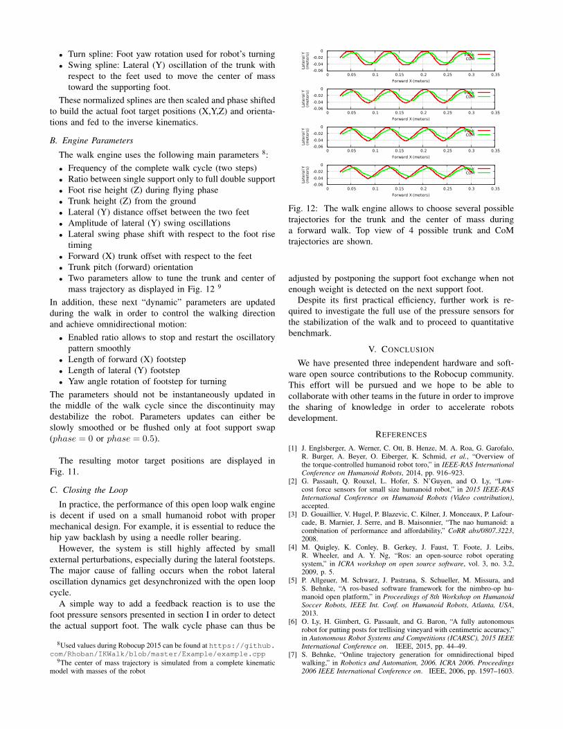
timing• Forward (X) trunk offset with respect to the feet• Trunk pitch (forward) orientation• Two parameters allow to tune the trunk and center of
mass trajectory as displayed in Fig. 12 9
In addition, these next “dynamic” parameters are updatedduring the walk in order to control the walking directionand achieve omnidirectional motion:
• Enabled ratio allows to stop and restart the oscillatorypattern smoothly
• Length of forward (X) footstep• Length of lateral (Y) footstep• Yaw angle rotation of footstep for turning
The parameters should not be instantaneously updated inthe middle of the walk cycle since the discontinuity maydestabilize the robot. Parameters updates can either beslowly smoothed or be flushed only at foot support swap(phase = 0 or phase = 0.5).
The resulting motor target positions are displayed inFig. 11.
C. Closing the Loop
In practice, the performance of this open loop walk engineis decent if used on a small humanoid robot with propermechanical design. For example, it is essential to reduce thehip yaw backlash by using a needle roller bearing.
However, the system is still highly affected by smallexternal perturbations, especially during the lateral footsteps.The major cause of falling occurs when the robot lateraloscillation dynamics get desynchronized with the open loopcycle.
A simple way to add a feedback reaction is to use thefoot pressure sensors presented in section I in order to detectthe actual support foot. The walk cycle phase can thus be
8Used values during Robocup 2015 can be found at https://github.com/Rhoban/IKWalk/blob/master/Example/example.cpp
9The center of mass trajectory is simulated from a complete kinematicmodel with masses of the robot
-0.06-0.04-0.02
0
0 0.05 0.1 0.15 0.2 0.25 0.3 0.35
Late
ral Y
(met
ers)
Forward X (meters)
TrunkCOM
-0.06-0.04-0.02
0
0 0.05 0.1 0.15 0.2 0.25 0.3 0.35
Late
ral Y
(met
ers)
Forward X (meters)
TrunkCOM
-0.06-0.04-0.02
0
0 0.05 0.1 0.15 0.2 0.25 0.3 0.35
Late
ral Y
(met
ers)
Forward X (meters)
TrunkCOM
-0.06-0.04-0.02
0
0 0.05 0.1 0.15 0.2 0.25 0.3 0.35
Late
ral Y
(met
ers)
Forward X (meters)
TrunkCOM
Fig. 12: The walk engine allows to choose several possibletrajectories for the trunk and the center of mass duringa forward walk. Top view of 4 possible trunk and CoMtrajectories are shown.
adjusted by postponing the support foot exchange when notenough weight is detected on the next support foot.
Despite its first practical efficiency, further work is re-quired to investigate the full use of the pressure sensors forthe stabilization of the walk and to proceed to quantitativebenchmark.
V. CONCLUSION
We have presented three independent hardware and soft-ware open source contributions to the Robocup community.This effort will be pursued and we hope to be able tocollaborate with other teams in the future in order to improvethe sharing of knowledge in order to accelerate robotsdevelopment.
REFERENCES
[1] J. Englsberger, A. Werner, C. Ott, B. Henze, M. A. Roa, G. Garofalo,R. Burger, A. Beyer, O. Eiberger, K. Schmid, et al., “Overview ofthe torque-controlled humanoid robot toro,” in IEEE-RAS InternationalConference on Humanoid Robots, 2014, pp. 916–923.
[2] G. Passault, Q. Rouxel, L. Hofer, S. N’Guyen, and O. Ly, “Low-cost force sensors for small size humanoid robot,” in 2015 IEEE-RASInternational Conference on Humanoid Robots (Video contribution),accepted.
[3] D. Gouaillier, V. Hugel, P. Blazevic, C. Kilner, J. Monceaux, P. Lafour-cade, B. Marnier, J. Serre, and B. Maisonnier, “The nao humanoid: acombination of performance and affordability,” CoRR abs/0807.3223,2008.
[4] M. Quigley, K. Conley, B. Gerkey, J. Faust, T. Foote, J. Leibs,R. Wheeler, and A. Y. Ng, “Ros: an open-source robot operatingsystem,” in ICRA workshop on open source software, vol. 3, no. 3.2,2009, p. 5.
[5] P. Allgeuer, M. Schwarz, J. Pastrana, S. Schueller, M. Missura, andS. Behnke, “A ros-based software framework for the nimbro-op hu-manoid open platform,” in Proceedings of 8th Workshop on HumanoidSoccer Robots, IEEE Int. Conf. on Humanoid Robots, Atlanta, USA,2013.
[6] O. Ly, H. Gimbert, G. Passault, and G. Baron, “A fully autonomousrobot for putting posts for trellising vineyard with centimetric accuracy,”in Autonomous Robot Systems and Competitions (ICARSC), 2015 IEEEInternational Conference on. IEEE, 2015, pp. 44–49.
[7] S. Behnke, “Online trajectory generation for omnidirectional bipedwalking,” in Robotics and Automation, 2006. ICRA 2006. Proceedings2006 IEEE International Conference on. IEEE, 2006, pp. 1597–1603.


![Optimal Power Allocation by Imperfect Hardware Analysis in ... · high rate systems such as LTE-Advanced and 5G networks exploiting inexpensive equipments [22]. Although most contributions](https://img.pdfslide.us/doc/110x75/60a3755fe220ff03896789dc/optimal-power-allocation-by-imperfect-hardware-analysis-in-high-rate-systems.jpg)