Embed Size (px)
Citation preview

1 This kit can be installed without removing thegas tank, however removal of the tank willmake the installation easier.
2 Remove seats and center console.
3 On passenger side of engine remove blowerassembly, items 41-56. (See diagram)
4 Install billet pulley onto starter pulley boss(#56), this will require the use of a press. (Seephoto). After the boss and pulley have beenpressed together thread the 6mm bolts thrupulley to ensure proper alignment of the pulleyonto the boss. Remove 6mm bolts.
RHINO INSTRUCTIONS
5 Install billet pulley and boss back onto engine.Torque bolt (#45) to 40 ft lbs. Loop belt overpulley. (See photo)
6 Install air shroud (#41) back onto engine usingthe three provided standoffs and bolts. You willneed to drill a hole thru the air shroud (#41) forthe top bolt and standoff. This only needs tobe done on the top most hole. (See photo)
7 Reinstall plate (#47), o-ring (#46), and fan(#43) onto pulley using the bolts provided.(See photo)
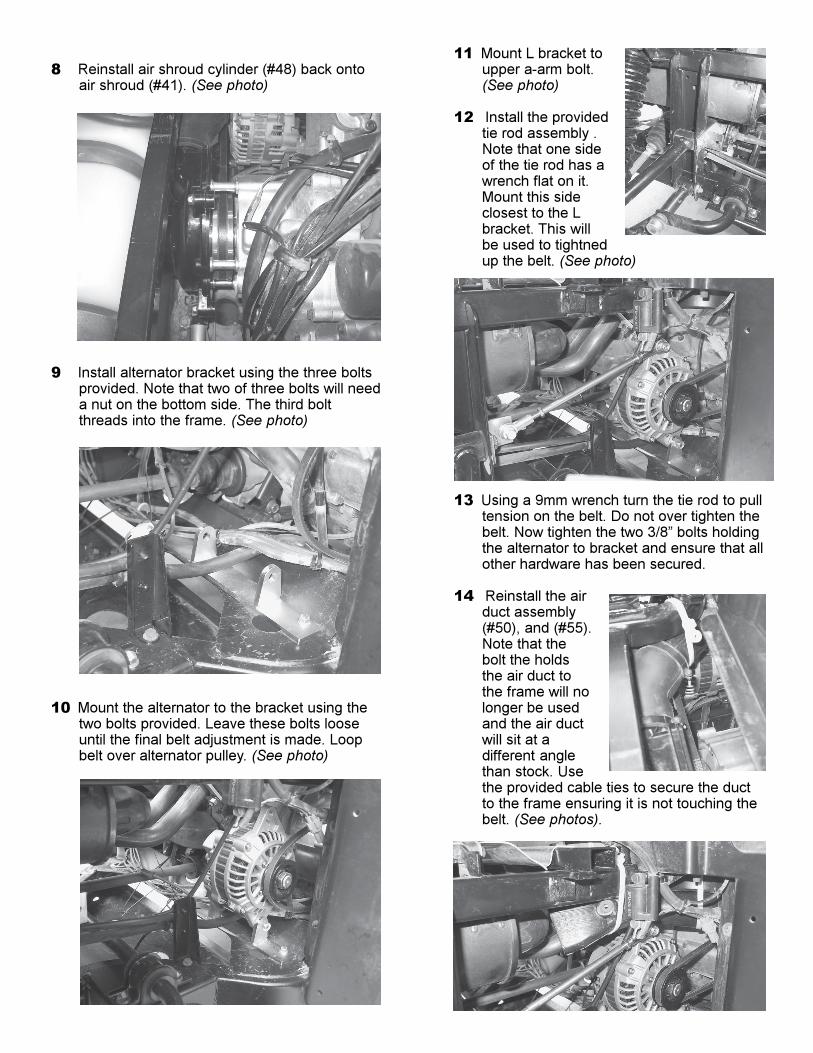
8 Reinstall air shroud cylinder (#48) back ontoair shroud (#41). (See photo)
9 Install alternator bracket using the three boltsprovided. Note that two of three bolts will needa nut on the bottom side. The third boltthreads into the frame. (See photo)
10 Mount the alternator to the bracket using thetwo bolts provided. Leave these bolts looseuntil the final belt adjustment is made. Loopbelt over alternator pulley. (See photo)
11 Mount L bracket toupper a-arm bolt.(See photo)
12 Install the providedtie rod assembly .Note that one sideof the tie rod has awrench flat on it.Mount this sideclosest to the Lbracket. This willbe used to tightnedup the belt. (See photo)
13 Using a 9mm wrench turn the tie rod to pulltension on the belt. Do not over tighten thebelt. Now tighten the two 3/8” bolts holdingthe alternator to bracket and ensure that allother hardware has been secured.
14 Reinstall the airduct assembly(#50), and (#55).Note that thebolt the holdsthe air duct tothe frame will nolonger be usedand the air ductwill sit at adifferent anglethan stock. Usethe provided cable ties to secure the ductto the frame ensuring it is not touching thebelt. (See photos).

15 Now it is time to wire up thekit. As you know the kit did notinclude a battery. We suggestyou purchase an automotivestyle battery and run all of youradditional electricalaccessories off of this battery.We have provided a wiring kitto charge the secondarybattery. We have also provideda schematic to help you wireup the kit.
16 The kit includes a relay that wesuggest you mount inside thestock battery box along withthe other relay and fuses.
17 There is also an adaptor plugincluded in the kit that plugsinto the back of the stock lightswitch. Locate the back of thestock light switch and unplugthe connector feeding theswitch. Insert our plug inbetween the switch and thestock wiring harness.
18 Refer to the schematic for theremaining wiring.
1 Pulley
2 Belt
3 Standoffs
4 Alternator Bracket
5 Alternator
6 L Bracket
7 Tie-rod Assembly
8 Cable Ties
9 Relay
10 Wire Harness
11 Battery Cables
12 Instructions