Embed Size (px)
Citation preview
April 2013 IMUX 2000 T1/E1IMUX 2000 T1/E1 1
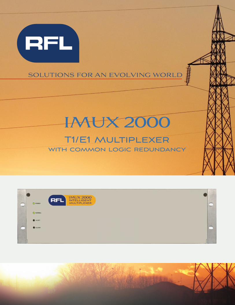
IMUX 2000T1/E1 Multiplexer
with common logic redundancy
SOLUTIONS FOR AN EVOLVING WORLD

April 2013 1 IMUX 2000 T1/E1
Your world is changing and so are we.
At RFL, we know your needs change much faster than your infrastructure. Our comprehensive line of solutions meets you wherever you are to help you bridge the gap from yesterday to tomorrow.
We aren’t just engineering products. We are continuously innovating to give legacy equipment the advantage of today’s technologies. Our highly adaptable solutions offer more features for more fl exibility and a custom fi t for your specifi c needs.
When we deliver, we also deliver our reputation. So when you open that box, you’re opening a custom-engineered solution, factory-tested and ready for deployment.
And as long as you own that equipment, you own the attention of RFL. We see you as our partner and we want to ensure that our solution is working for you – now and over the long haul.RFL – delivering solutions that work. Period.
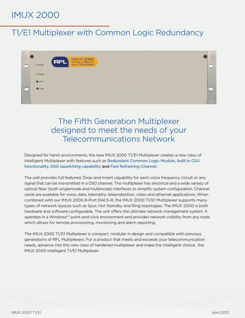
IMUX 2000
T1/E1 Multiplexer with Common Logic Redundancy
The Fifth Generation Multiplexerdesigned to meet the needs of your
Telecommunications Network
Designed for harsh environments, the new IMUX 2000 T1/E1 Multiplexer creates a new class of
Intelligent Multiplexer with features such as Redundant Common Logic Module, built in CSU
functionality, DS0 squelching capability and Fast Reframing Channel.
The unit provides full featured, Drop-and-Insert capability for each voice frequency circuit or any
signal that can be transmitted in a DS0 channel. The multiplexer has electrical and a wide variety of
optical fi ber (both singlemode and multimode) interfaces to simplify system confi guration. Channel
cards are available for voice, data, telemetry, teleprotection, video and ethernet applications. When
combined with our IMUX 2000 8-Port DACS-R, the IMUX 2000 T1/E1 Multiplexer supports many
types of network layouts such as Spur, Hot Standby and Ring topologies. The IMUX 2000 is both
hardware and software confi gurable. The unit offers the ultimate network management system. It
operates in a Windows™ point-and-click environment and provides network visibility from any node
which allows for remote provisioning, monitoring and alarm reporting.
The IMUX 2000 T1/E1 Multiplexer is compact, modular in design and compatible with previous
generations of RFL Multiplexers. For a product that meets and exceeds your telecommunication
needs, advance into this new class of hardened multiplexer and make the Intelligent choice, the
IMUX 2000 Intelligent T1/E1 Multiplexer.
IMUX 2000 T1/E1 April 2013
April 2013 2 IMUX 2000 T1/E1
Substation Hardened The IMUX 2000 T1/E1 Multiplehxer is designed for harsh environments and has a wide temperature range of -20°C to +65°C (-4°F to +149°F). It meets the IEEE/ANSI standards C.37.90-1989, C.37.90.1 and C.37.90.2 for SWC, fast transient and EMI. It is CE approved and has been tested to BS EN 5002:1995. It is also FCC part 15 Class A approved.
Reliability The IMUX 2000 provides enhanced reliability by offering optional redundant power supplies and common logic modules.
Speed The IMUX 2000 is designed to handle time sensitive applications such as Protective Relaying. The Drop-and-Insert through-channel delay is less than 25 microseconds. The IMUX 2000 has an average reframe time of less than 25 milliseconds and also has the ability to enable a Fast Reframing Channel (FRC) for less than 1 millisecond reframing.
DS0 SquelchingThe IMUX 2000 T1/E1 Multiplexer has the ability to squelch (turn off) the output of a channel module in the Multiplexer upon loss of synchronization. This feature provides security against false tripping on 4-wire analog transfer trip channels and older digital equipment (with limited error checking) during loss of sync and protects against ‘pink’ noise conditions, which result from cross-talk or the frame search. This feature is ideal for preventing false tripping due to system malfunction.
CSU FunctionalityThe IMUX 2000 offers a built in CSU functionality that meets applicable standards for protection including FCC Part 68 approval for direct connection into the Public Switched Telephone Network (PSTN). When enabled, the unit will respond to generated loopback codes compliant to either ANSI T1.403 or AT&T TR 54016. It will also maintain and allow local and remote retrieval of performance measurements in accordance with either ANSI T1.403 or AT&T TR 54016.
Modular Design The IMUX 2000 incorporates a midplane motherboard design. Channel modules plug into the front of the unit, and matching module adapter for I/O connections plug into the rear. This eliminates the need for internal chassis wiring when adding new channel cards, simplifying the upgrade.
Fiber Optic or Electric Interfaces The IMUX 2000 can be equipped with either electrical T1/E1 interfaces or Optical Interface Adapters (OIA’s). The electrical T1 interface is equipped with Line Build-Out (LBO) networks for operation of up to 6,000 feet from the DSX. The OIA’s are available in a wide range of multimode, single-mode, LED or laser combinations to accommodate 1300nm and 1550nm wavelengths.
Channel Interfaces A wide range of interfaces unique to the utility and the transportation market is offered. It also offers a wide range of Voice and Data, Status, Telemetry, Ethernet, Transfer Trip and Video channel interfaces to meet most communications requirements.
Fast Restoration When applied to diverse communication routes, such as Ring or Hot-Standby networks, the IMUX 2000 is capable of switch times programmable down to 1 millisecond.
Diverse Networks The IMUX 2000 supports many types of network layouts such as Linear, Spurs, Hot-Standby and Ring topologies.It is also designed for operation over SONET/SDHnetworks taking into consideration the critical time-delay issues associated with Protective Relaying.
SONET and SDH Applications Protective Relaying can fi nally be applied over non-proprietary SONET/SDH equipment. With emphasis placed on rapid break healing, the IMUX 2000 addresses the critical time issues associated with Protective Relaying making it the ideal and Intelligent choice when interfacing to SONET/SDH networks. The IMUX 2000 bridges the gap between SONET and substations providing DS0 gateways onto the network. Also, through its own switching techniques, can overcome the longer switch times and unequal channel delay issues associated with SONET.
Automation The IMUX 2000 offers the ultimate GUI Network Management system which operates in a WindowsTM point-and-click environment. The optional SNMP based management reporting software can be used when integrated as part of a larger enterprise system. Network visibility is available from any node which allows remote provisioning, monitoring and alarm reporting.
Key Features and Benefi ts
April 2013 6 IMUX 2000 T1/E1 IMUX 2000 T1/E1 3 April 2013
Telecommunications Solutions
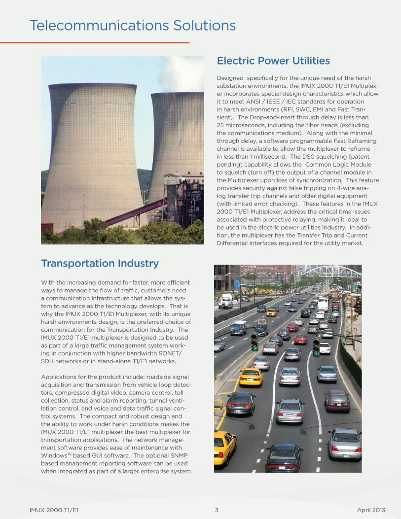
Transportation Industry
With the increasing demand for faster, more effi cient ways to manage the fl ow of traffi c, customers need a communication infrastructure that allows the sys-tem to advance as the technology develops. That is why the IMUX 2000 T1/E1 Multiplexer, with its unique harsh environments design, is the preferred choice of communication for the Transportation Industry. The IMUX 2000 T1/E1 multiplexer is designed to be used as part of a large traffi c management system work-ing in conjunction with higher bandwidth SONET/SDH networks or in stand-alone T1/E1 networks.
Applications for the product include: roadside signal acquisition and transmission from vehicle loop detec-tors, compressed digital video, camera control, toll collection, status and alarm reporting, tunnel venti-lation control, and voice and data traffi c signal con-trol systems. The compact and robust design and the ability to work under harsh conditions makes the IMUX 2000 T1/E1 multiplexer the best multiplexer for transportation applications. The network manage-ment software provides ease of maintenance with Windows™ based GUI software. The optional SNMP based management reporting software can be used when integrated as part of a larger enterprise system.
Electric Power Utilities
Designed specifi cally for the unique need of the harsh substation environments, the IMUX 2000 T1/E1 Multiplex-er incorporates special design characteristics which allow it to meet ANSI / IEEE / IEC standards for operation in harsh environments (RFI, SWC, EMI and Fast Tran-sient). The Drop-and-Insert through delay is less than 25 microseconds, including the fi ber heads (excluding the communications medium). Along with the minimal through delay, a software programmable Fast Reframing channel is available to allow the multiplexer to reframe in less than 1 millisecond. The DS0 squelching (patent pending) capability allows the Common Logic Module to squelch (turn off) the output of a channel module in the Multiplexer upon loss of synchronization. This feature provides security against false tripping on 4-wire ana-log transfer trip channels and older digital equipment (with limited error checking). These features in the IMUX 2000 T1/E1 Multiplexer, address the critical time issues associated with protective relaying, making it ideal to be used in the electric power utilities industry. In addi-tion, the multiplexer has the Transfer Trip and Current Differential interfaces required for the utility market.
April 2013 4 IMUX 2000 T1/E1
Application Solutions
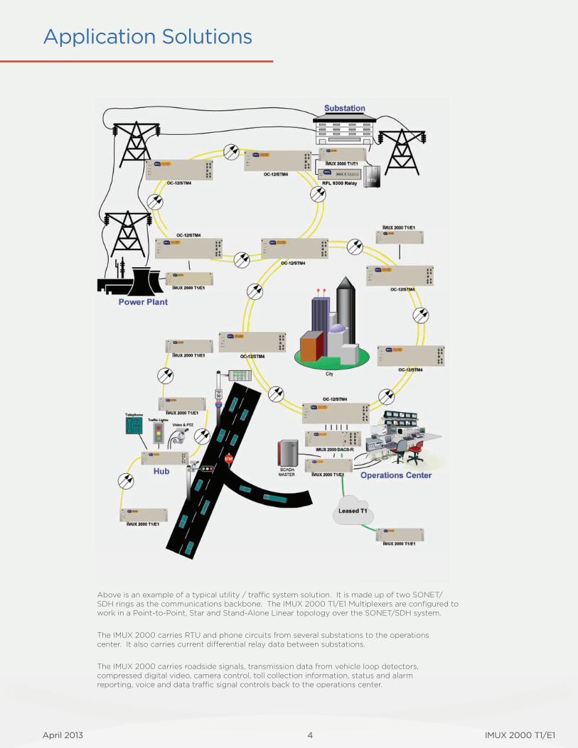
Above is an example of a typical utility / tra c system solution. It is made up of two SONET/SDH rings as the communications backbone. The IMUX 2000 T1/E1 Multiplexers are confi gured to work in a Point-to-Point, Star and Stand-Alone Linear topology over the SONET/SDH system.
The IMUX 2000 carries RTU and phone circuits from several substations to the operations center. It also carries current di� erential relay data between substations.
The IMUX 2000 carries roadside signals, transmission data from vehicle loop detectors, compressed digital video, camera control, toll collection information, status and alarm reporting, voice and data tra c signal controls back to the operations center.
April 2013 4 IMUX 2000 T1/E1 IMUX 2000 T1/E1 5 April 2013
Technical Specifi cations
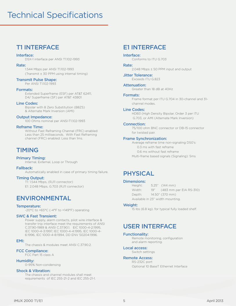
T1 INTERFACEInterface:
DSX-1 interface per ANSI T1.102-1993
Rate: 1.544 Mbps per ANSI T1.102-1993 (Transmit ± 30 PPM using internal timing)
Transmit Pulse Shape: Per ANSI T1.102-1993
Formats: Extended Superframe (ESF) per AT&T 62411, D4/ Superframe (SF) per AT&T 43801
Line Codes: Bipolar with 8 Zero Substitution (B8ZS) & Alternate Mark Inversion (AMI)
Output Impedance: 100 Ohms nominal per ANSI-T1.102-1993
Reframe Time: Without Fast Reframing Channel (FRC) enabled: Less than 25 milliseconds. With Fast Reframing channel (FRC) enabled: Less than 1ms.
TIMINGPrimary Timing:
Internal, External, Loop or Through
Fallback: Automatically enabled in case of primary timing failure.
Timing Output:T1: 1.544 Mbps, (RJ11 connector)E1: 2.048 Mbps, G.703 (RJ11 connector)
ENVIRONMENTALTemperature:
-20°C to +65°C (-4°F to +149°F) operating
SWC & Fast Transient: Power supply, alarm contacts, pilot wire interface & transfer trip interface meet the requirements of ANSI C.37.90-1989 & ANSI C.37.90.1. EIC 1000-4-2:1995, IEC 1000-4-3:1997, IEC 1000-4-4:1995, IEC 1000-4-6:1996, IEC 1000-4-8:1994, DD ENV 50204:1996.
EMI: The chassis & modules meet ANSI C.37.90.2.
FCC Compliance: FCC Part 15 class A
Humidity: 0-95% Non-condensing
Shock & Vibration:The chassis and channel modules shall meet requirements of IEC 255-21-2 and IEC 255-21-1.
E1 INTERFACEInterface:
Conforms to ITU G.703
Rate: 2.048 Mbps ± 50 PPM input and output
Jitter Tolerance:Exceeds ITU G.823
Attenuation: Greater than 18 dB at 40Hz
Formats: Frame format per ITU G.704 in 30-channel and 31-channel modes.
Line Codes: HDB3 (High Density Bipolar, Order 3 per ITU G.703, or AMI (Alternate Mark Inversion)
Connection: 75/100 ohm BNC connector or DB-15 connector for twisted pair.
Frame Synchronization: Average reframe time non-signaling DS0’s: 0.3 ms with fast reframe 0.6 ms without fast reframeMulti-frame based signals (Signaling): 5ms
PHYSICALDimensions:
Height: 5.25” (144 mm)Width: 19” (483 mm per EIA RS-310)Depth: 14.50” (370 mm)Available in 23” width mounting.
Weight:15 lbs (6.8 kg). for typical fully loaded shelf.
USER INTERFACEFunctionality:
Remote monitoring, confi guration and alarm reporting.
Local access:Switch settings
Remote Access:RS-232C portOptional 10 BaseT Ethernet Interface
April 2013 6 IMUX 2000 T1/E1
Technical Specifi cations (continued)
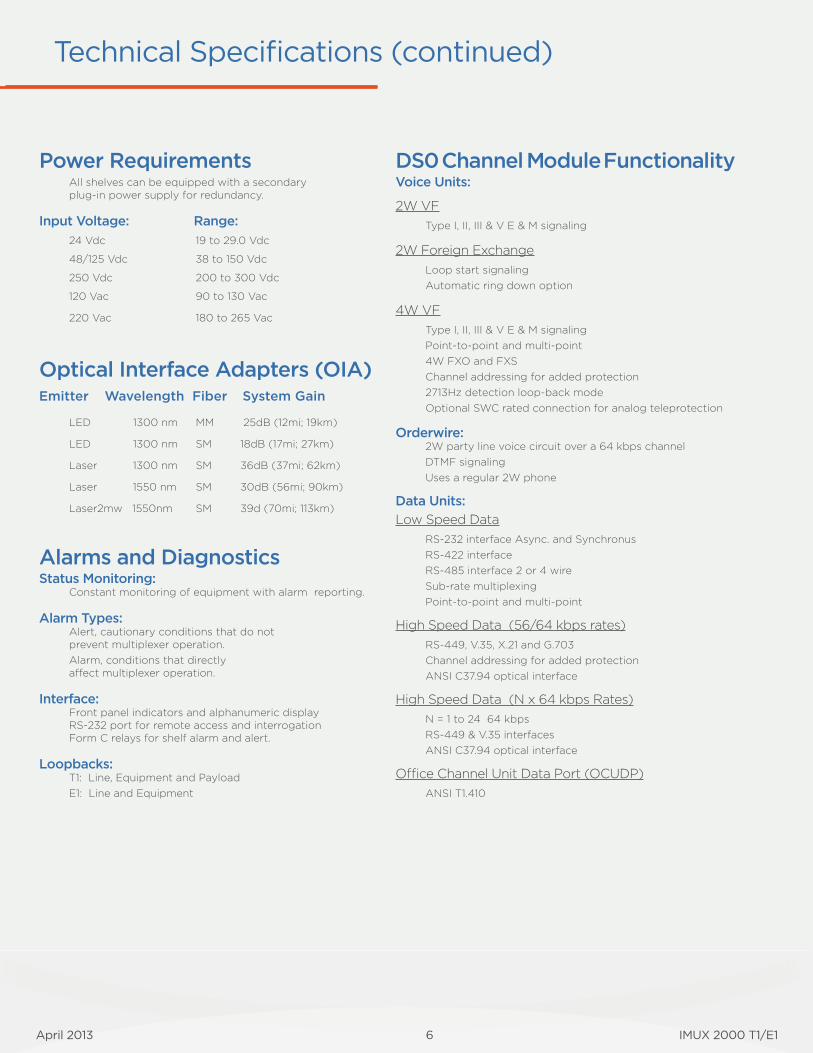
Power RequirementsAll shelves can be equipped with a secondary plug-in power supply for redundancy.
Input Voltage: Range:
24 Vdc 19 to 29.0 Vdc
48/125 Vdc 38 to 150 Vdc
250 Vdc 200 to 300 Vdc
120 Vac 90 to 130 Vac
220 Vac 180 to 265 Vac
Optical Interface Adapters (OIA)Emitter Wavelength Fiber System Gain
LED 1300 nm MM 25dB (12mi; 19km)
LED 1300 nm SM 18dB (17mi; 27km)
Laser 1300 nm SM 36dB (37mi; 62km)
Laser 1550 nm SM 30dB (56mi; 90km)
Laser2mw 1550nm SM 39d (70mi; 113km)
Alarms and DiagnosticsStatus Monitoring:
Constant monitoring of equipment with alarm reporting.
Alarm Types: Alert, cautionary conditions that do not prevent multiplexer operation. Alarm, conditions that directly a� ect multiplexer operation.
Interface: Front panel indicators and alphanumeric displayRS-232 port for remote access and interrogationForm C relays for shelf alarm and alert.
Loopbacks:T1: Line, Equipment and PayloadE1: Line and Equipment
DS0 Channel Module FunctionalityVoice Units:
2W VFType I, II, III & V E & M signaling
2W Foreign ExchangeLoop start signalingAutomatic ring down option
4W VFType I, II, III & V E & M signalingPoint-to-point and multi-point4W FXO and FXSChannel addressing for added protection2713Hz detection loop-back modeOptional SWC rated connection for analog teleprotection
Orderwire:2W party line voice circuit over a 64 kbps channelDTMF signalingUses a regular 2W phone
Data Units:
Low Speed DataRS-232 interface Async. and SynchronusRS-422 interfaceRS-485 interface 2 or 4 wireSub-rate multiplexingPoint-to-point and multi-point
High Speed Data (56/64 kbps rates)RS-449, V.35, X.21 and G.703Channel addressing for added protectionANSI C37.94 optical interface
High Speed Data (N x 64 kbps Rates)N = 1 to 24 64 kbpsRS-449 & V.35 interfacesANSI C37.94 optical interface
O ce Channel Unit Data Port (OCUDP)ANSI T1.410
IMUX 2000 T1/E1 7 April 2013
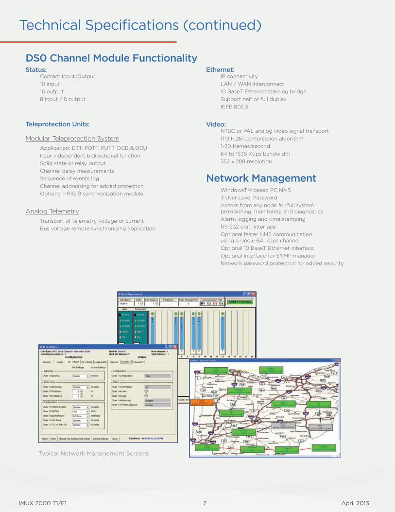
DS0 Channel Module FunctionalityStatus:
Contact Input/Output16 input16 output8 input / 8 output
Teleprotection Units:
Modular Teleprotection SystemApplication: DTT, POTT, PUTT, DCB & DCUFour independent bidirectional functionSolid state or relay outputChannel delay measurementsSequence of events logChannel addressing for added protectionOptional I-RIG B synchronization module
Analog TelemetryTransport of telemetry voltage or currentBus voltage remote synchronizing application
Ethernet:IP connectivityLAN / WAN interconnect10 BaseT Ethernet learning bridgeSupport half or full duplexIEEE 802.3
Video:NTSC or PAL analog video signal transportITU H.261 compression algorithm1-20 frames/second64 to 1536 Kbps bandwidth352 x 288 resolution
Network ManagementWindowsTM based PC NMS3 User Level Password Access from any node for full system provisioning, monitoring and diagnosticsAlarm logging and time stampingRS-232 craft interfaceOptional faster NMS communication using a single 64 kbps channelOptional 10 BaseT Ethernet InterfaceOptional interface for SNMP managerNetwork password protection for added security
Typical Network Management Screens
Technical Specifi cations (continued)
April 2013 12 IMUX 2000 T1/E1
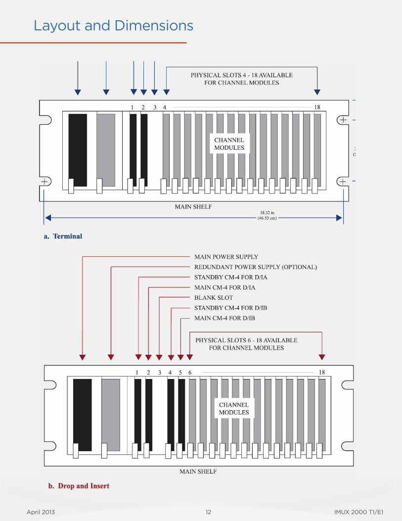
Layout and Dimensions

Your world is changing and so are we.
IMUX 2000 T1/E1 April 2013
Notes

April 2013 IMUX 2000 T1/E1
RFL Electronics Inc.353 Powerville Road
Boonton, NJ 07005, USA
Tel: 973.334.3100Fax:973.334.3863www.rfl elect.com