Embed Size (px)
Citation preview
Certificates and reports shall not be reproduced except in full, without the written permission of H.B Compliance Solutions, LLC.
RF Test Report
For the
Microchip Technology Inc.
IEEE 802.15.4 RF Transceiver Module with PA/LNA
Tested under
ETSI EN 300 328 V1.8.1 for
Wideband transmission systems; Data transmission equipment operating in 2.4GHz ISM band
February 21, 2014
Prepared for:
Microchip Technology Inc.
2355 W. Chandler Blvd.
Chandler, Arizona 85224
Prepared By:
H.B. Compliance Solutions
5005 S. Ash Avenue, Suite # A-10
Tempe, Arizona 85282
Reviewed By:
Hoosamuddin Bandukwala
Cert # ATL-0062-E
Engineering Statement: The measurements shown in this report were made in accordance with the procedure
indicated, and the emissions from this equipment were found to be within the limits applicable. I assume full
responsibility for the accuracy and completeness of these measurements, and for the qualifications of all
persons taking them. It is further stated that upon the basis of the measurement made, the equipment tested is
capable of operation in accordance with the requirements of ETSI EN 300 328 Rules under normal use and
maintenance.
HBCS Report # RF_13052_3 Page 2 of 36
Report Status Sheet
Revision # Report Date Reason for Revision
Ø February 21, 2014 Initial Issue
HBCS Report # RF_13052_3 Page 3 of 36
Table of Contents
EXECUTIVE SUMMARY ............................................................................................ 4
1. Testing Summary ........................................................................................ 4
EQUIPMENT CONFIGURATION ................................................................................ 5
1. Overview .................................................................................................... 5
2. Test Facility ................................................................................................. 6
3. Description of Test Sample ......................................................................... 6
4. Equipment Configuration ........................................................................... 6
5. Support Equipment .................................................................................... 7
6. Ports and Cabling Information .................................................................... 7
7. Method of Monitoring EUT Operation ........................................................ 7
8. Mode of Operation ..................................................................................... 7
9. Modifications ............................................................................................. 7
10. Disposition of EUT ...................................................................................... 8
Criteria for Transmitter Test Suite .......................................................................... 9
1. RF Output Power & Duty Cycle ................................................................... 9
2. Power Spectral Density ............................................................................. 13
3. Medium Utilization (MU) factor ............................................................... 16
4. Occupied Channel Bandwidth ................................................................... 18
5. Transmitter unwanted emissions in the out-of-band domain................... 20
6. Transmitter Spurious Emissions ................................................................ 23
7. Receiver Spurious Emissions ..................................................................... 28
Test Setup Photos ................................................................................................. 34
I. Test Equipment .............................................................................................. 36
HBCS Report # RF_13052_3 Page 4 of 36
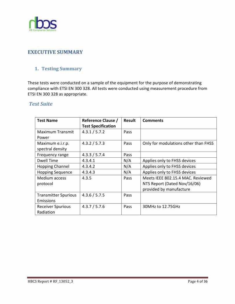
EXECUTIVE SUMMARY
1. Testing Summary
These tests were conducted on a sample of the equipment for the purpose of demonstrating
compliance with ETSI EN 300 328. All tests were conducted using measurement procedure from
ETSI EN 300 328 as appropriate.
Test Suite
Test Name Reference Clause /
Test Specification
Result Comments
Maximum Transmit
Power
4.3.1 / 5.7.2 Pass
Maximum e.i.r.p.
spectral density
4.3.2 / 5.7.3 Pass Only for modulations other than FHSS
Frequency range 4.3.3 / 5.7.4 Pass
Dwell Time 4.3.4.1 N/A Applies only to FHSS devices
Hopping Channel 4.3.4.2 N/A Applies only to FHSS devices
Hopping Sequence 4.3.4.3 N/A Applies only to FHSS devices
Medium access
protocol
4.3.5 Pass Meets IEEE 802.15.4 MAC. Reviewed
NTS Report (Dated Nov/16/06)
provided by manufacture
Transmitter Spurious
Emissions
4.3.6 / 5.7.5 Pass
Receiver Spurious
Radiation
4.3.7 / 5.7.6 Pass 30MHz to 12.75GHz
HBCS Report # RF_13052_3 Page 5 of 36
EQUIPMENT CONFIGURATION
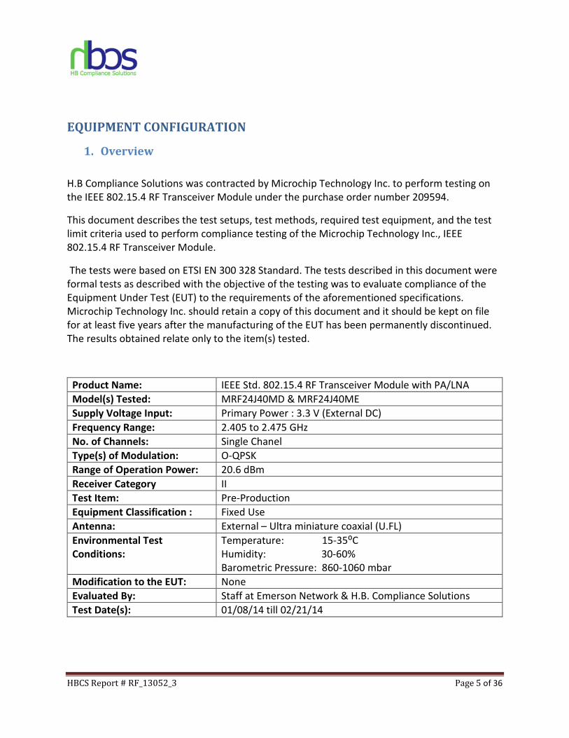
1. Overview
H.B Compliance Solutions was contracted by Microchip Technology Inc. to perform testing on
the IEEE 802.15.4 RF Transceiver Module under the purchase order number 209594.
This document describes the test setups, test methods, required test equipment, and the test
limit criteria used to perform compliance testing of the Microchip Technology Inc., IEEE
802.15.4 RF Transceiver Module.
The tests were based on ETSI EN 300 328 Standard. The tests described in this document were
formal tests as described with the objective of the testing was to evaluate compliance of the
Equipment Under Test (EUT) to the requirements of the aforementioned specifications.
Microchip Technology Inc. should retain a copy of this document and it should be kept on file
for at least five years after the manufacturing of the EUT has been permanently discontinued.
The results obtained relate only to the item(s) tested.
Product Name: IEEE Std. 802.15.4 RF Transceiver Module with PA/LNA
Model(s) Tested: MRF24J40MD & MRF24J40ME
Supply Voltage Input: Primary Power : 3.3 V (External DC)
Frequency Range: 2.405 to 2.475 GHz
No. of Channels: Single Chanel
Type(s) of Modulation: O-QPSK
Range of Operation Power: 20.6 dBm
Receiver Category II
Test Item: Pre-Production
Equipment Classification : Fixed Use
Antenna: External – Ultra miniature coaxial (U.FL)
Environmental Test
Conditions:
Temperature: 15-35⁰C
Humidity: 30-60%
Barometric Pressure: 860-1060 mbar
Modification to the EUT: None
Evaluated By: Staff at Emerson Network & H.B. Compliance Solutions
Test Date(s): 01/08/14 till 02/21/14
HBCS Report # RF_13052_3 Page 6 of 36
2. Test Facility
Radiated Emission testing was performed at Emerson Network Power. This facility is located at
2900 S. Diablo Way, Suite 190, Tempe, AZ 85282. All equipment used in making physical
determination is accurate and bears recent traceability to the National Institute of Standards
and Technology.
Test facility at Emerson Network power is an A2LA accredited test site. The A2LA certificate
number is 2716.01. The scope of accreditation covers the FCC Method - 47 CFR Part 15, ICES-
003, CISPR 22, AS/NZS 3548 and VCCI.
Conducted testing was performed at H.B. Compliance Solutions. This facility is located at 5005
S. Ash Avenue, Suite # A-10, Tempe AZ-85282
Radiated Emissions measurements were performed in a semi-anechoic chamber (equivalent to
an Open Area Test Site). In accordance with §2.948(a)(3), a complete site description is
contained at Emerson Network Power.
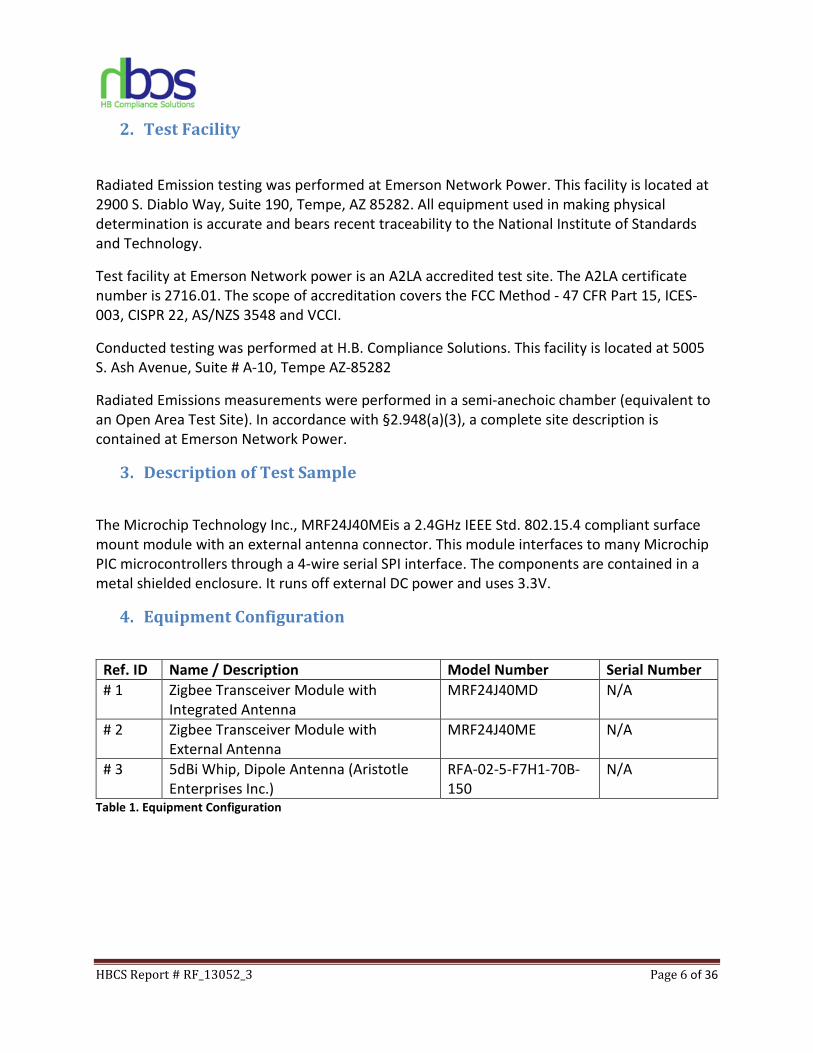
3. Description of Test Sample
The Microchip Technology Inc., MRF24J40MEis a 2.4GHz IEEE Std. 802.15.4 compliant surface
mount module with an external antenna connector. This module interfaces to many Microchip
PIC microcontrollers through a 4-wire serial SPI interface. The components are contained in a
metal shielded enclosure. It runs off external DC power and uses 3.3V.
4. Equipment Configuration
Ref. ID Name / Description Model Number Serial Number
# 1 Zigbee Transceiver Module with
Integrated Antenna
MRF24J40MD N/A
# 2 Zigbee Transceiver Module with
External Antenna
MRF24J40ME N/A
# 3 5dBi Whip, Dipole Antenna (Aristotle
Enterprises Inc.)
RFA-02-5-F7H1-70B-
150
N/A
Table 1. Equipment Configuration
HBCS Report # RF_13052_3 Page 7 of 36
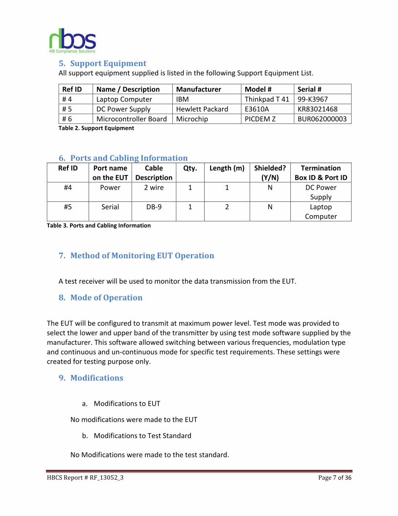
5. Support Equipment All support equipment supplied is listed in the following Support Equipment List.
Ref ID Name / Description Manufacturer Model # Serial #
# 4 Laptop Computer IBM Thinkpad T 41 99-K3967
# 5 DC Power Supply Hewlett Packard E3610A KR83021468
# 6 Microcontroller Board Microchip PICDEM Z BUR062000003 Table 2. Support Equipment
6. Ports and Cabling Information Ref ID Port name
on the EUT
Cable
Description
Qty. Length (m) Shielded?
(Y/N)
Termination
Box ID & Port ID
#4 Power 2 wire 1 1 N DC Power
Supply
#5 Serial DB-9 1 2 N Laptop
Computer Table 3. Ports and Cabling Information
7. Method of Monitoring EUT Operation
A test receiver will be used to monitor the data transmission from the EUT.
8. Mode of Operation
The EUT will be configured to transmit at maximum power level. Test mode was provided to
select the lower and upper band of the transmitter by using test mode software supplied by the
manufacturer. This software allowed switching between various frequencies, modulation type
and continuous and un-continuous mode for specific test requirements. These settings were
created for testing purpose only.
9. Modifications
a. Modifications to EUT
No modifications were made to the EUT
b. Modifications to Test Standard
No Modifications were made to the test standard.
HBCS Report # RF_13052_3 Page 8 of 36
10. Disposition of EUT
The test sample including all support equipment submitted to H.B Compliance Solutions for
testing will be returned to Microchip Technology Inc. upon completion of testing.
HBCS Report # RF_13052_3 Page 9 of 36
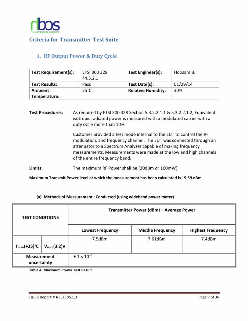
Criteria for Transmitter Test Suite
1. RF Output Power & Duty Cycle
Test Requirement(s): ETSI 300 328
§4.3.2.1
Test Engineer(s): Hoosam B.
Test Results: Pass Test Date(s): 01/29/14
Ambient
Temperature:
25˚C Relative Humidity: 30%
Test Procedures: As required by ETSI 300 328 Section 5.3.2.2.1.1 & 5.3.2.2.1.2, Equivalent
isotropic radiated power is measured with a modulated carrier with a
duty cycle more than 10%.
Customer provided a test mode internal to the EUT to control the RF
modulation, and frequency channel. The EUT was connected through an
attenuator to a Spectrum Analyzer capable of making frequency
measurements. Measurements were made at the low and high channels
of the entire frequency band.
Limits: The maximum RF Power shall be (20dBm or 100mW)
Maximum Transmit Power level at which the measurement has been calculated is 19.59 dBm
(a) Methods of Measurement : Conducted (using wideband power meter)
TEST CONDITIONS
Transmitter Power (dBm) – Average Power
Lowest Frequency Middle Frequency Highest Frequency
Tnom(+25)°C
Vnom(3.2)V
7.5dBm 7.61dBm 7.4dBm
Measurement
uncertainty
± 1 × 10¯⁷
Table 4. Maximum Power Test Result
HBCS Report # RF_13052_3 Page 10 of 36
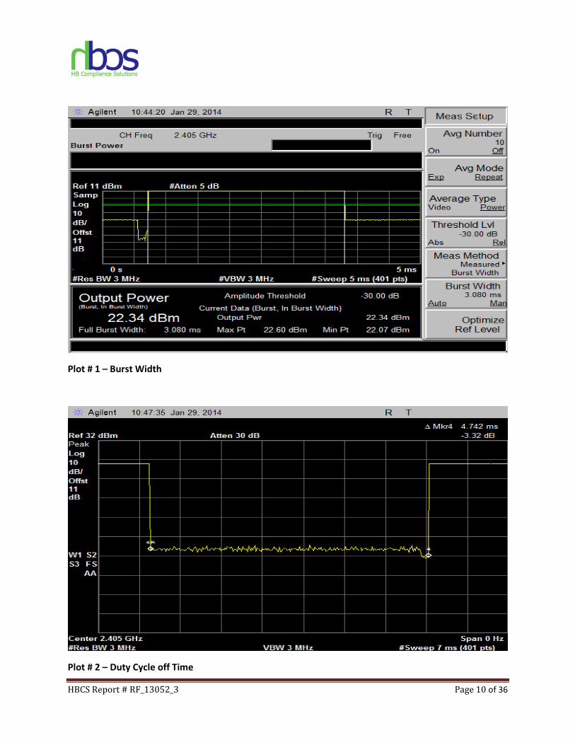
Plot # 1 – Burst Width
Plot # 2 – Duty Cycle off Time
HBCS Report # RF_13052_3 Page 11 of 36
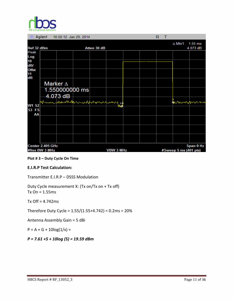
Plot # 3 – Duty Cycle On Time
E.I.R.P Test Calculation:
Transmitter E.I.R.P – DSSS Modulation
Duty Cycle measurement X: (Tx on/Tx on + Tx off)
Tx On = 1.55ms
Tx Off = 4.742ms
Therefore Duty Cycle = 1.55/(1.55+4.742) = 0.2ms = 20%
Antenna Assembly Gain = 5 dBi
P = A + G + 10log(1/x) =
P = 7.61 +5 + 10log (5) = 19.59 dBm
HBCS Report # RF_13052_3 Page 12 of 36
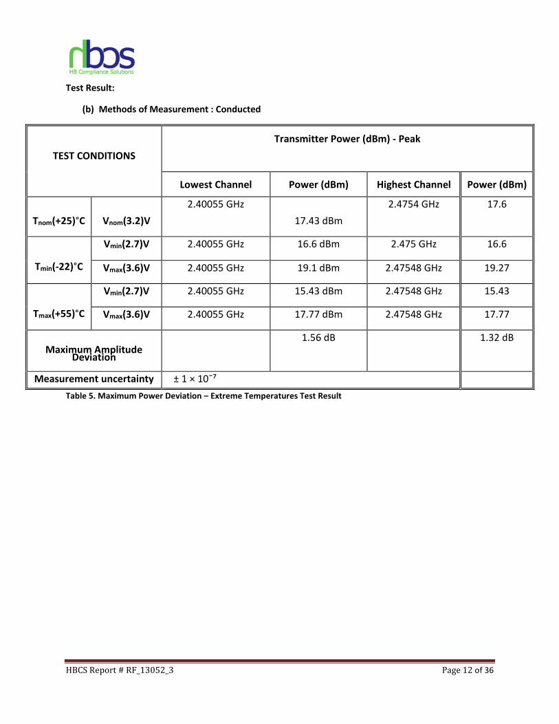
Test Result:
(b) Methods of Measurement : Conducted
TEST CONDITIONS
Transmitter Power (dBm) - Peak
Lowest Channel Power (dBm) Highest Channel Power (dBm)
Tnom(+25)°C
Vnom(3.2)V
2.40055 GHz
17.43 dBm
2.4754 GHz 17.6
Tmin(-22)°C
Vmin(2.7)V 2.40055 GHz 16.6 dBm 2.475 GHz 16.6
Vmax(3.6)V 2.40055 GHz 19.1 dBm 2.47548 GHz 19.27
Tmax(+55)°C
Vmin(2.7)V 2.40055 GHz 15.43 dBm 2.47548 GHz 15.43
Vmax(3.6)V 2.40055 GHz 17.77 dBm 2.47548 GHz 17.77
Maximum Amplitude Deviation
1.56 dB 1.32 dB
Measurement uncertainty ± 1 × 10¯⁷
Table 5. Maximum Power Deviation – Extreme Temperatures Test Result
HBCS Report # RF_13052_3 Page 13 of 36
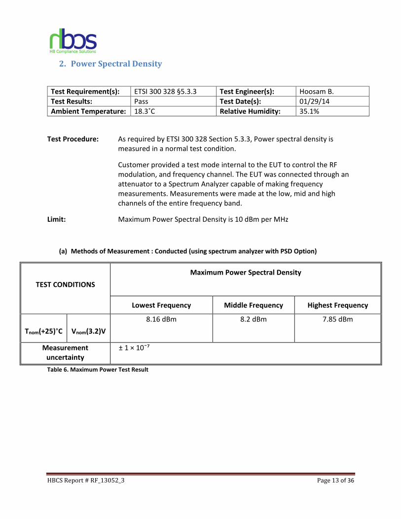
2. Power Spectral Density
Test Requirement(s): ETSI 300 328 §5.3.3 Test Engineer(s): Hoosam B.
Test Results: Pass Test Date(s): 01/29/14
Ambient Temperature: 18.3˚C Relative Humidity: 35.1%
Test Procedure: As required by ETSI 300 328 Section 5.3.3, Power spectral density is
measured in a normal test condition.
Customer provided a test mode internal to the EUT to control the RF
modulation, and frequency channel. The EUT was connected through an
attenuator to a Spectrum Analyzer capable of making frequency
measurements. Measurements were made at the low, mid and high
channels of the entire frequency band.
Limit: Maximum Power Spectral Density is 10 dBm per MHz
(a) Methods of Measurement : Conducted (using spectrum analyzer with PSD Option)
TEST CONDITIONS
Maximum Power Spectral Density
Lowest Frequency Middle Frequency Highest Frequency
Tnom(+25)°C
Vnom(3.2)V
8.16 dBm 8.2 dBm 7.85 dBm
Measurement
uncertainty
± 1 × 10¯⁷
Table 6. Maximum Power Test Result
HBCS Report # RF_13052_3 Page 14 of 36
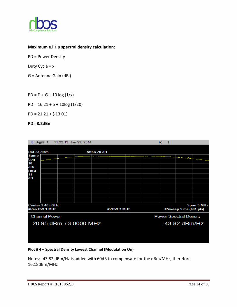
Maximum e.i.r.p spectral density calculation:
PD = Power Density
Duty Cycle = x
G = Antenna Gain (dBi)
PD = D + G + 10 log (1/x)
PD = 16.21 + 5 + 10log (1/20)
PD = 21.21 + (-13.01)
PD= 8.2dBm
Plot # 4 – Spectral Density Lowest Channel (Modulation On)
Notes: -43.82 dBm/Hz is added with 60dB to compensate for the dBm/MHz, therefore
16.18dBm/MHz
HBCS Report # RF_13052_3 Page 15 of 36
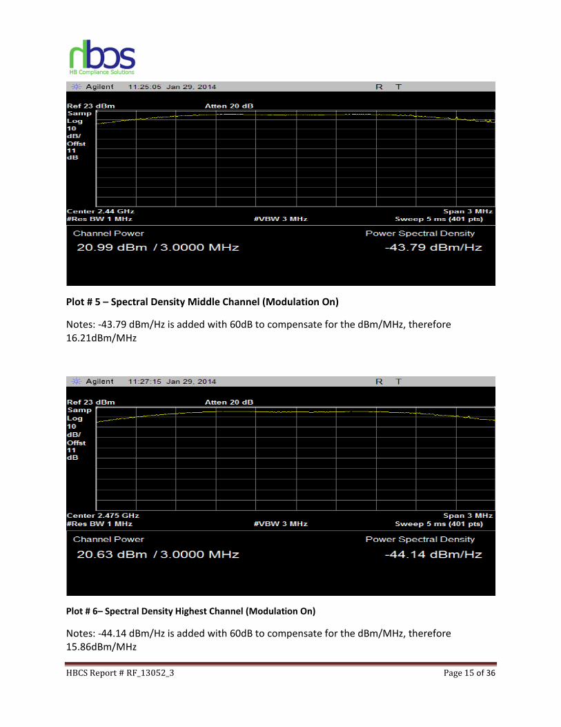
Plot # 5 – Spectral Density Middle Channel (Modulation On)
Notes: -43.79 dBm/Hz is added with 60dB to compensate for the dBm/MHz, therefore
16.21dBm/MHz
Plot # 6– Spectral Density Highest Channel (Modulation On)
Notes: -44.14 dBm/Hz is added with 60dB to compensate for the dBm/MHz, therefore
15.86dBm/MHz
HBCS Report # RF_13052_3 Page 16 of 36
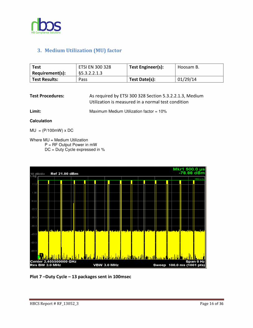
3. Medium Utilization (MU) factor
Test
Requirement(s):
ETSI EN 300 328
§5.3.2.2.1.3
Test Engineer(s): Hoosam B.
Test Results: Pass Test Date(s): 01/29/14
Test Procedures: As required by ETSI 300 328 Section 5.3.2.2.1.3, Medium
Utilization is measured in a normal test condition
Limit: Maximum Medium Utilization factor = 10%
Calculation
MU = (P/100mW) x DC Where MU = Medium Utilization P = RF Output Power in mW DC = Duty Cycle expressed in %
Plot 7 –Duty Cycle – 13 packages sent in 100msec
HBCS Report # RF_13052_3 Page 17 of 36
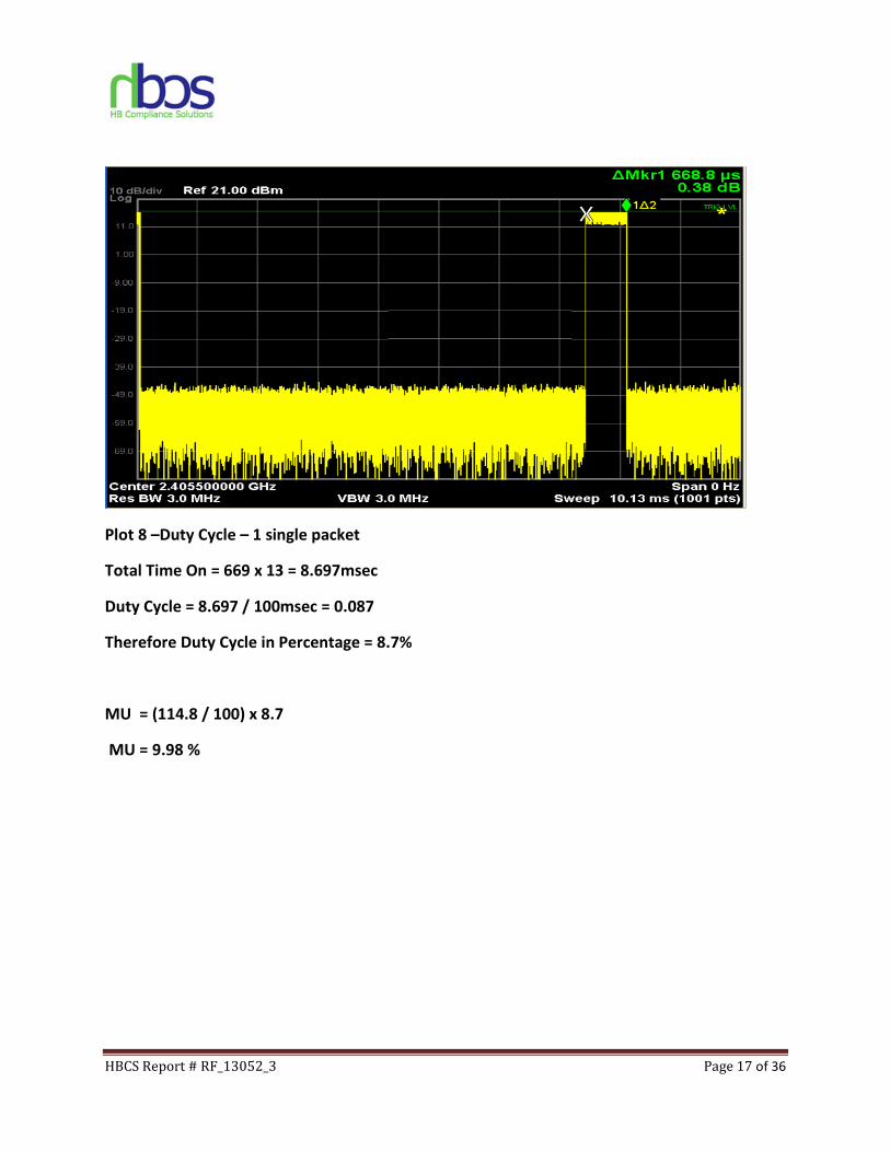
Plot 8 –Duty Cycle – 1 single packet
Total Time On = 669 x 13 = 8.697msec
Duty Cycle = 8.697 / 100msec = 0.087
Therefore Duty Cycle in Percentage = 8.7%
MU = (114.8 / 100) x 8.7
MU = 9.98 %
HBCS Report # RF_13052_3 Page 18 of 36
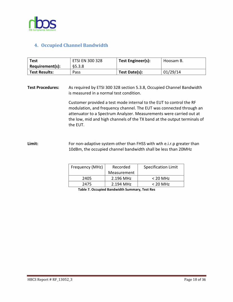
4. Occupied Channel Bandwidth
Test
Requirement(s):
ETSI EN 300 328
§5.3.8
Test Engineer(s): Hoosam B.
Test Results: Pass Test Date(s): 01/29/14
Test Procedures: As required by ETSI 300 328 section 5.3.8, Occupied Channel Bandwidth
is measured in a normal test condition.
Customer provided a test mode internal to the EUT to control the RF
modulation, and frequency channel. The EUT was connected through an
attenuator to a Spectrum Analyzer. Measurements were carried out at
the low, mid and high channels of the TX band at the output terminals of
the EUT.
Limit: For non-adaptive system other than FHSS with wth e.i.r.p greater than
10dBm, the occupied channel bandwidth shall be less than 20MHz
Frequency (MHz) Recorded
Measurement
Specification Limit
2405 2.196 MHz < 20 MHz
2475 2.194 MHz < 20 MHz Table 7. Occupied Bandwidth Summary, Test Res
HBCS Report # RF_13052_3 Page 19 of 36
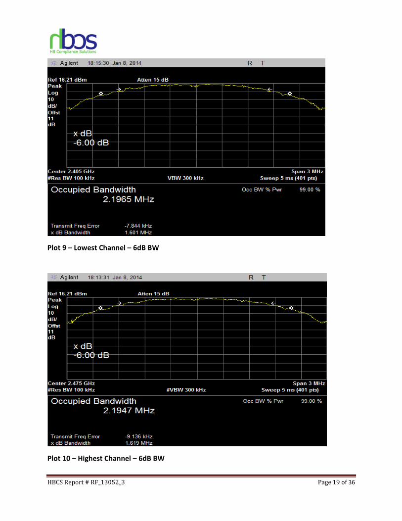
Plot 9 – Lowest Channel – 6dB BW
Plot 10 – Highest Channel – 6dB BW
HBCS Report # RF_13052_3 Page 20 of 36
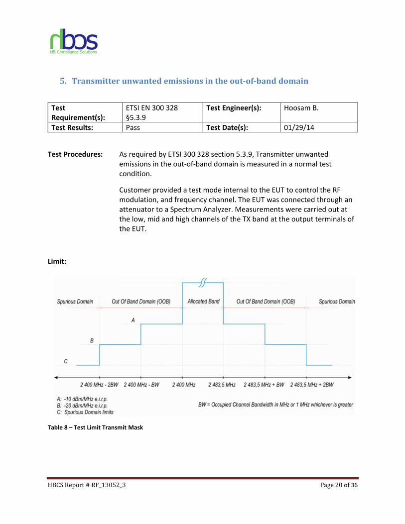
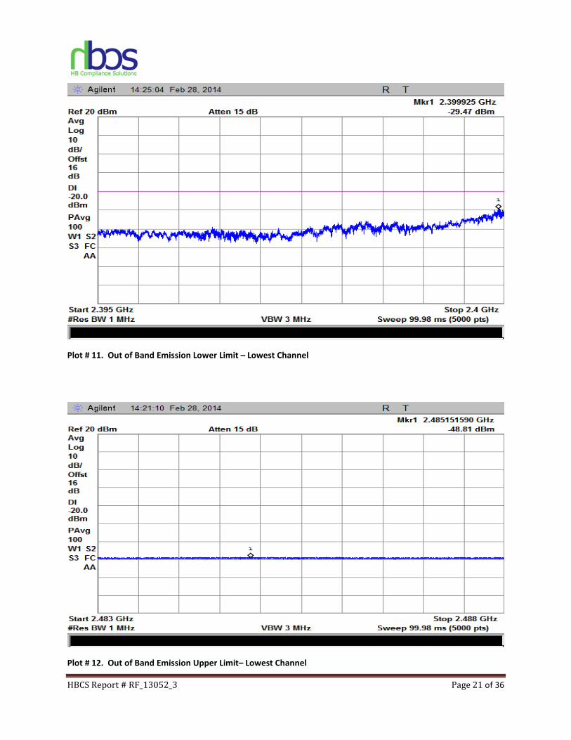
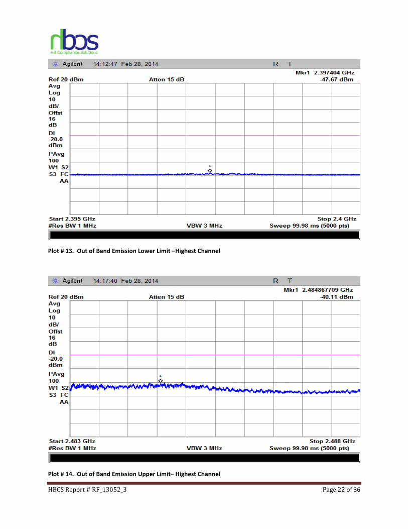
5. Transmitter unwanted emissions in the out-of-band domain
Test
Requirement(s):
ETSI EN 300 328
§5.3.9
Test Engineer(s): Hoosam B.
Test Results: Pass Test Date(s): 01/29/14
Test Procedures: As required by ETSI 300 328 section 5.3.9, Transmitter unwanted
emissions in the out-of-band domain is measured in a normal test
condition.
Customer provided a test mode internal to the EUT to control the RF
modulation, and frequency channel. The EUT was connected through an
attenuator to a Spectrum Analyzer. Measurements were carried out at
the low, mid and high channels of the TX band at the output terminals of
the EUT.
Limit:
Table 8 – Test Limit Transmit Mask
HBCS Report # RF_13052_3 Page 21 of 36
Plot # 11. Out of Band Emission Lower Limit – Lowest Channel
Plot # 12. Out of Band Emission Upper Limit– Lowest Channel
HBCS Report # RF_13052_3 Page 22 of 36
Plot # 13. Out of Band Emission Lower Limit –Highest Channel
Plot # 14. Out of Band Emission Upper Limit– Highest Channel
HBCS Report # RF_13052_3 Page 23 of 36
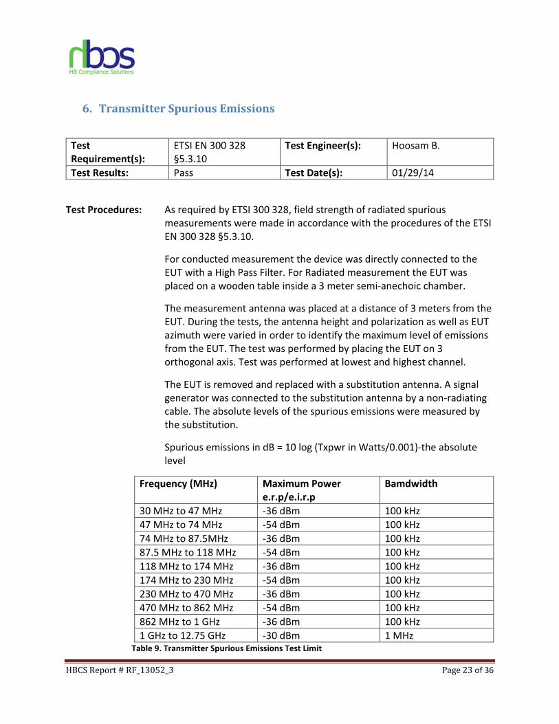
6. Transmitter Spurious Emissions
Test
Requirement(s):
ETSI EN 300 328
§5.3.10
Test Engineer(s): Hoosam B.
Test Results: Pass Test Date(s): 01/29/14
Test Procedures: As required by ETSI 300 328, field strength of radiated spurious
measurements were made in accordance with the procedures of the ETSI
EN 300 328 §5.3.10.
For conducted measurement the device was directly connected to the
EUT with a High Pass Filter. For Radiated measurement the EUT was
placed on a wooden table inside a 3 meter semi-anechoic chamber.
The measurement antenna was placed at a distance of 3 meters from the
EUT. During the tests, the antenna height and polarization as well as EUT
azimuth were varied in order to identify the maximum level of emissions
from the EUT. The test was performed by placing the EUT on 3
orthogonal axis. Test was performed at lowest and highest channel.
The EUT is removed and replaced with a substitution antenna. A signal
generator was connected to the substitution antenna by a non-radiating
cable. The absolute levels of the spurious emissions were measured by
the substitution.
Spurious emissions in dB = 10 log (Txpwr in Watts/0.001)-the absolute
level
Frequency (MHz) Maximum Power
e.r.p/e.i.r.p
Bamdwidth
30 MHz to 47 MHz -36 dBm 100 kHz
47 MHz to 74 MHz -54 dBm 100 kHz
74 MHz to 87.5MHz -36 dBm 100 kHz
87.5 MHz to 118 MHz -54 dBm 100 kHz
118 MHz to 174 MHz -36 dBm 100 kHz
174 MHz to 230 MHz -54 dBm 100 kHz
230 MHz to 470 MHz -36 dBm 100 kHz
470 MHz to 862 MHz -54 dBm 100 kHz
862 MHz to 1 GHz -36 dBm 100 kHz
1 GHz to 12.75 GHz -30 dBm 1 MHz Table 9. Transmitter Spurious Emissions Test Limit
HBCS Report # RF_13052_3 Page 24 of 36
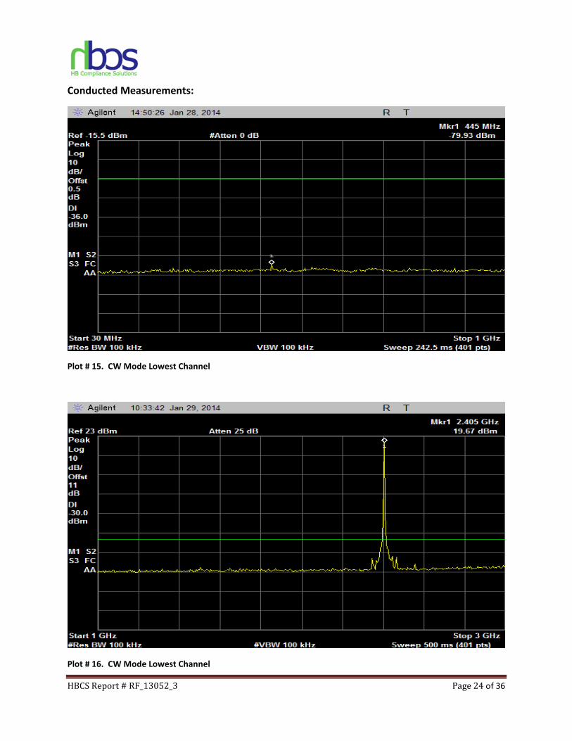
Conducted Measurements:
Plot # 15. CW Mode Lowest Channel
Plot # 16. CW Mode Lowest Channel

HBCS Report # RF_13052_3 Page 25 of 36
Plot # 17. CW Mode Lowest Channel
Plot # 18. CW Mode Highest Channel
HBCS Report # RF_13052_3 Page 26 of 36
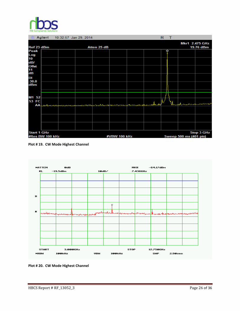
Plot # 19. CW Mode Highest Channel
Plot # 20. CW Mode Highest Channel
HBCS Report # RF_13052_3 Page 27 of 36
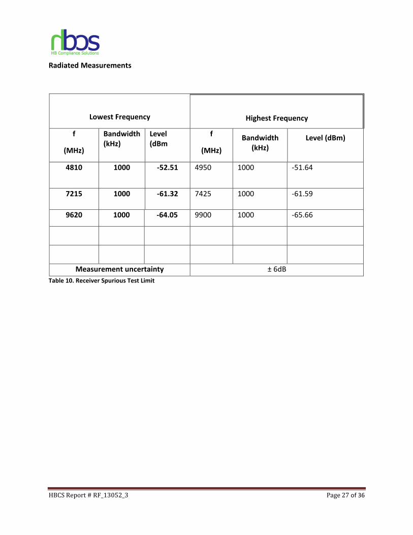
Radiated Measurements
Lowest Frequency
Highest Frequency
f
(MHz)
Bandwidth
(kHz)
Level
(dBm
f
(MHz)
Bandwidth
(kHz)
Level (dBm)
4810 1000 -52.51 4950 1000 -51.64
7215 1000 -61.32 7425 1000 -61.59
9620 1000 -64.05 9900 1000 -65.66
Measurement uncertainty ± 6dB
Table 10. Receiver Spurious Test Limit
HBCS Report # RF_13052_3 Page 28 of 36
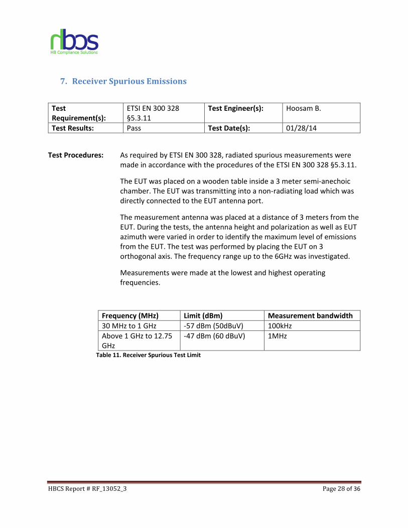
7. Receiver Spurious Emissions
Test
Requirement(s):
ETSI EN 300 328
§5.3.11
Test Engineer(s): Hoosam B.
Test Results: Pass Test Date(s): 01/28/14
Test Procedures: As required by ETSI EN 300 328, radiated spurious measurements were
made in accordance with the procedures of the ETSI EN 300 328 §5.3.11.
The EUT was placed on a wooden table inside a 3 meter semi-anechoic
chamber. The EUT was transmitting into a non-radiating load which was
directly connected to the EUT antenna port.
The measurement antenna was placed at a distance of 3 meters from the
EUT. During the tests, the antenna height and polarization as well as EUT
azimuth were varied in order to identify the maximum level of emissions
from the EUT. The test was performed by placing the EUT on 3
orthogonal axis. The frequency range up to the 6GHz was investigated.
Measurements were made at the lowest and highest operating
frequencies.
Frequency (MHz) Limit (dBm) Measurement bandwidth
30 MHz to 1 GHz -57 dBm (50dBuV) 100kHz
Above 1 GHz to 12.75
GHz
-47 dBm (60 dBuV) 1MHz
Table 11. Receiver Spurious Test Limit
HBCS Report # RF_13052_3 Page 29 of 36
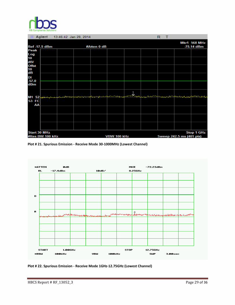
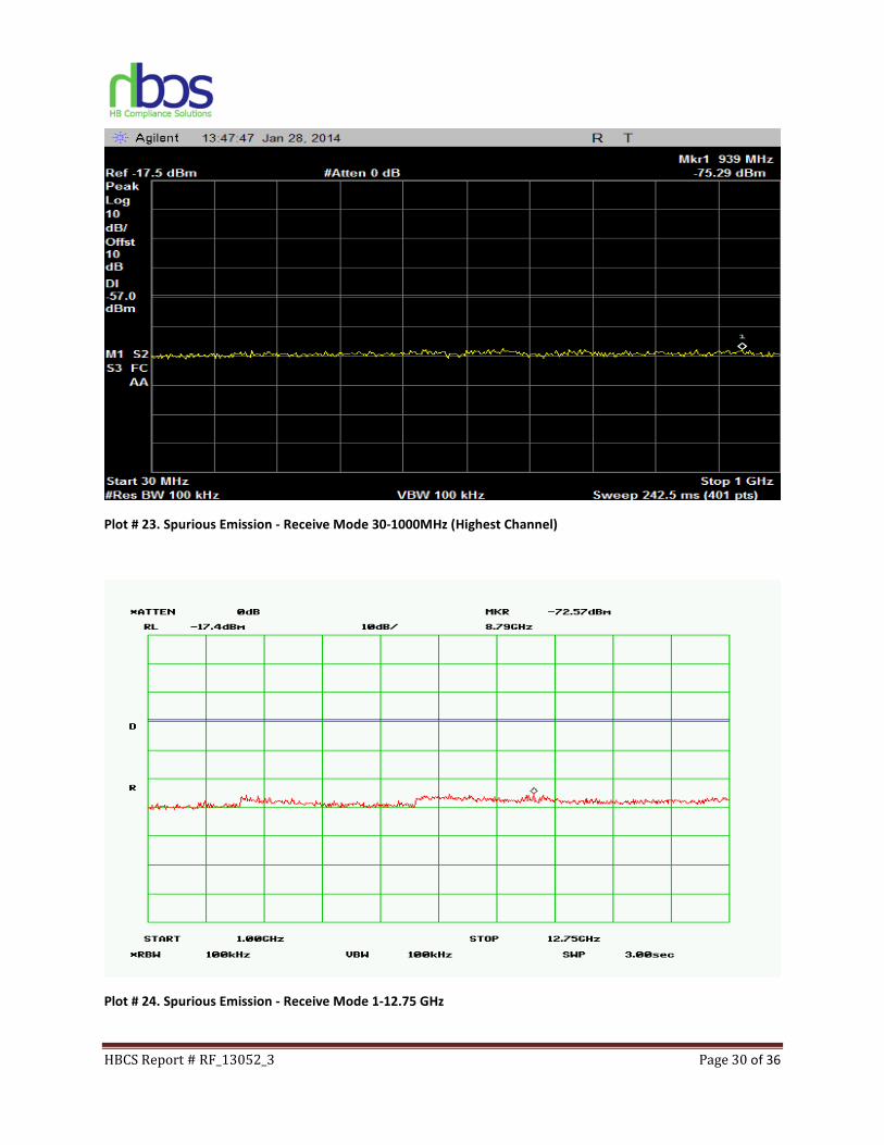
Plot # 21. Spurious Emission - Receive Mode 30-1000MHz (Lowest Channel)
Plot # 22. Spurious Emission - Receive Mode 1GHz-12.75GHz (Lowest Channel)
HBCS Report # RF_13052_3 Page 30 of 36
Plot # 23. Spurious Emission - Receive Mode 30-1000MHz (Highest Channel)
Plot # 24. Spurious Emission - Receive Mode 1-12.75 GHz
HBCS Report # RF_13052_3 Page 31 of 36
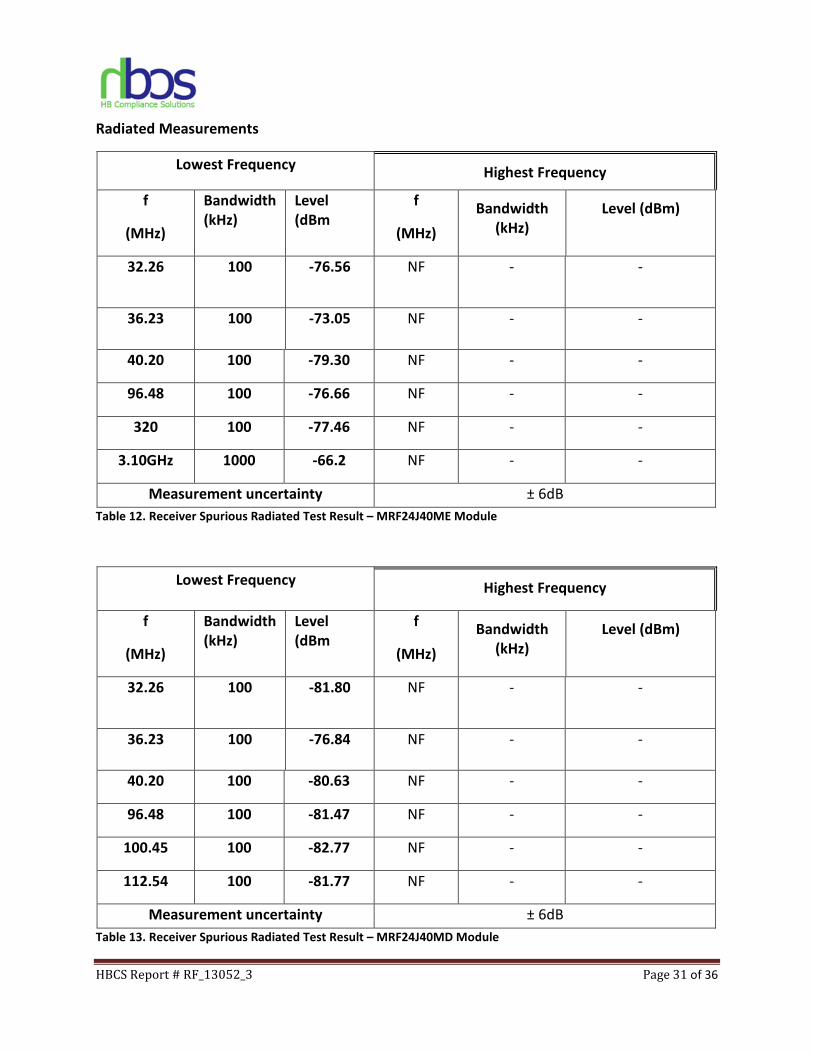
Radiated Measurements
Lowest Frequency Highest Frequency
f
(MHz)
Bandwidth
(kHz)
Level
(dBm
f
(MHz)
Bandwidth
(kHz)
Level (dBm)
32.26 100 -76.56 NF - -
36.23 100 -73.05 NF - -
40.20 100 -79.30 NF - -
96.48 100 -76.66 NF - -
320 100 -77.46 NF - -
3.10GHz 1000 -66.2 NF - -
Measurement uncertainty ± 6dB
Table 12. Receiver Spurious Radiated Test Result – MRF24J40ME Module
Lowest Frequency Highest Frequency
f
(MHz)
Bandwidth
(kHz)
Level
(dBm
f
(MHz)
Bandwidth
(kHz)
Level (dBm)
32.26 100 -81.80 NF - -
36.23 100 -76.84 NF - -
40.20 100 -80.63 NF - -
96.48 100 -81.47 NF - -
100.45 100 -82.77 NF - -
112.54 100 -81.77 NF - -
Measurement uncertainty ± 6dB
Table 13. Receiver Spurious Radiated Test Result – MRF24J40MD Module

HBCS Report # RF_13052_3 Page 32 of 36
Plot # 25. Spurious Emission - Receive Mode 30-1000MHz – MRF24J40ME Module
Plot # 26. Spurious Emission - Receive Mode 30-1000MHz – MRF24J40MD Module
0
10
20
30
40
50
60
70
80
Level [dBµV/m]
30M40M 50M 70M 100M 200M 300M400M 600M 1G
Frequency [Hz]
MES ME_1-16_0_pre PK LIM FCC_Class B_3M
0
10
20
30
40
50
60
70
80
Level [dBµV/m]
30M40M 50M 70M 100M 200M 300M 400M 600M 1G
Frequency [Hz]
x
x
x xx xx
x xMES MD_1-16_0_red PK MES MD_1-16_0_pre PK LIM FCC_Class B_3M
HBCS Report # RF_13052_3 Page 33 of 36
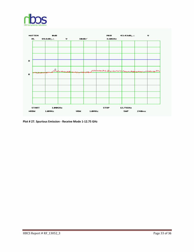
Plot # 27. Spurious Emission - Receive Mode 1-12.75 GHz
HBCS Report # RF_13052_3 Page 34 of 36
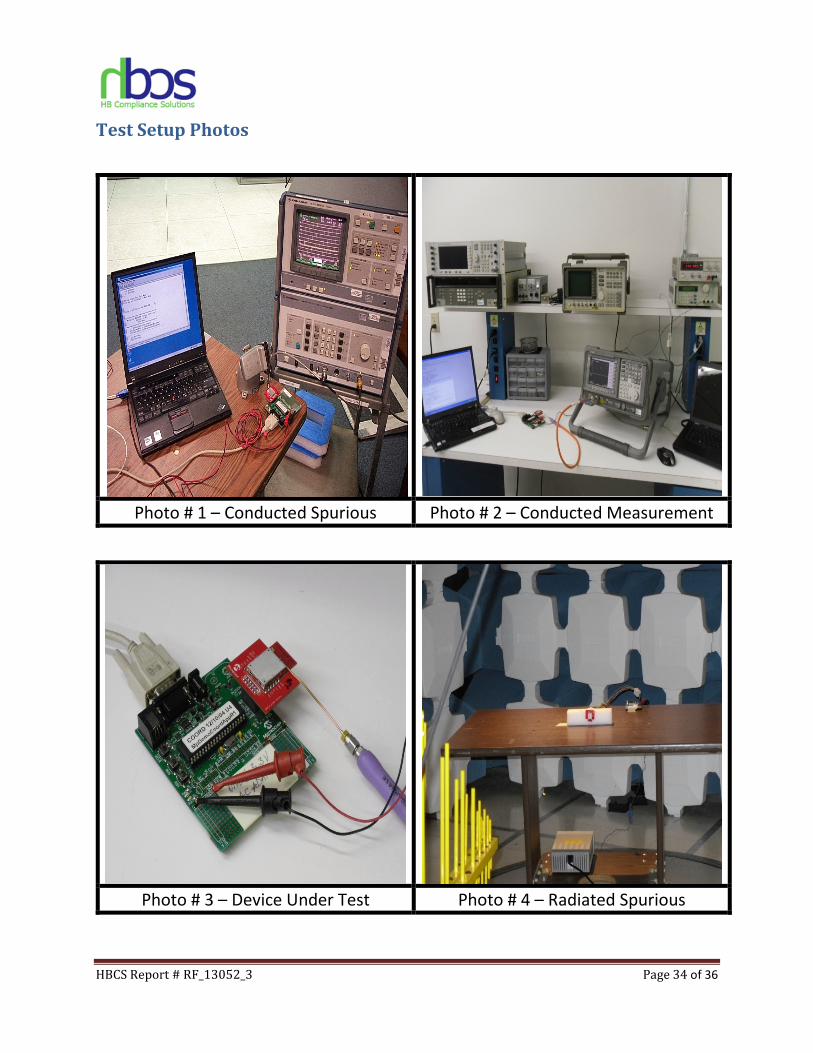
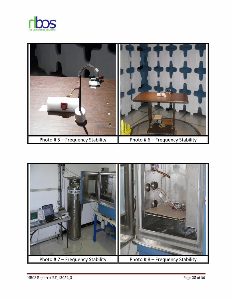
Test Setup Photos
Photo # 1 – Conducted Spurious Photo # 2 – Conducted Measurement
Photo # 3 – Device Under Test Photo # 4 – Radiated Spurious
HBCS Report # RF_13052_3 Page 35 of 36
Photo # 5 – Frequency Stability Photo # 6 – Frequency Stability
Photo # 7 – Frequency Stability Photo # 8 – Frequency Stability
HBCS Report # RF_13052_3 Page 36 of 36
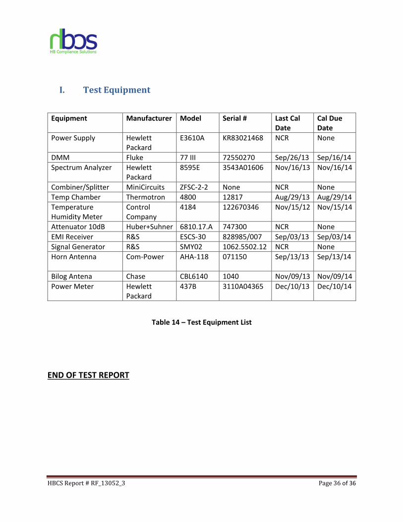
I. Test Equipment
Equipment Manufacturer Model Serial # Last Cal
Date
Cal Due
Date
Power Supply Hewlett
Packard
E3610A KR83021468 NCR None
DMM Fluke 77 III 72550270 Sep/26/13 Sep/16/14
Spectrum Analyzer Hewlett
Packard
8595E 3543A01606
Nov/16/13 Nov/16/14
Combiner/Splitter MiniCircuits ZFSC-2-2 None NCR None
Temp Chamber Thermotron 4800 12817 Aug/29/13 Aug/29/14
Temperature
Humidity Meter
Control
Company
4184 122670346 Nov/15/12 Nov/15/14
Attenuator 10dB Huber+Suhner 6810.17.A 747300 NCR None
EMI Receiver R&S ESCS-30 828985/007 Sep/03/13 Sep/03/14
Signal Generator R&S SMY02 1062.5502.12 NCR None
Horn Antenna Com-Power AHA-118 071150
Sep/13/13 Sep/13/14
Bilog Antena Chase CBL6140 1040 Nov/09/13 Nov/09/14
Power Meter Hewlett
Packard
437B 3110A04365 Dec/10/13 Dec/10/14
Table 14 – Test Equipment List
END OF TEST REPORT