Embed Size (px)
Citation preview
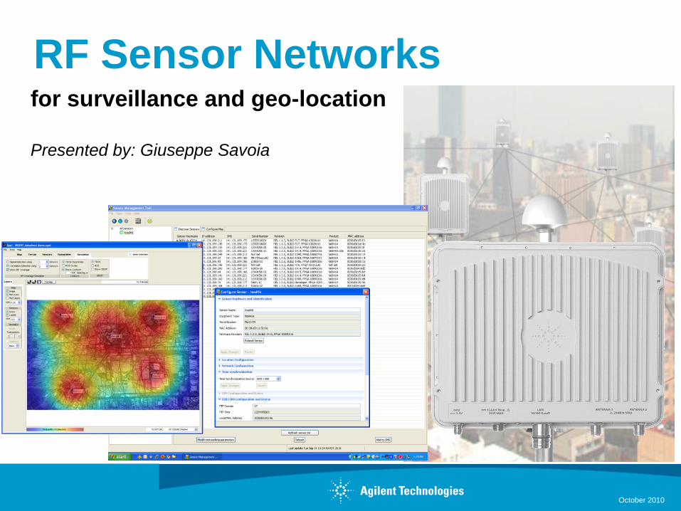
for surveillance and geo-location
Presented by: Giuseppe Savoia
RF Sensor Networks
October 2010
Creating Sensor Networks with the N6841A
S800 Module 305
RF Sensor Networks Overview
October 2010
• Why RF Sensors
• Key Capabilities and Applications
• RF Sensor main features
• Monitoring & Analysis Software
• Emitter Geolocation Software
• Summary
Page 2
Creating Sensor Networks with the N6841A
S800 Module 305
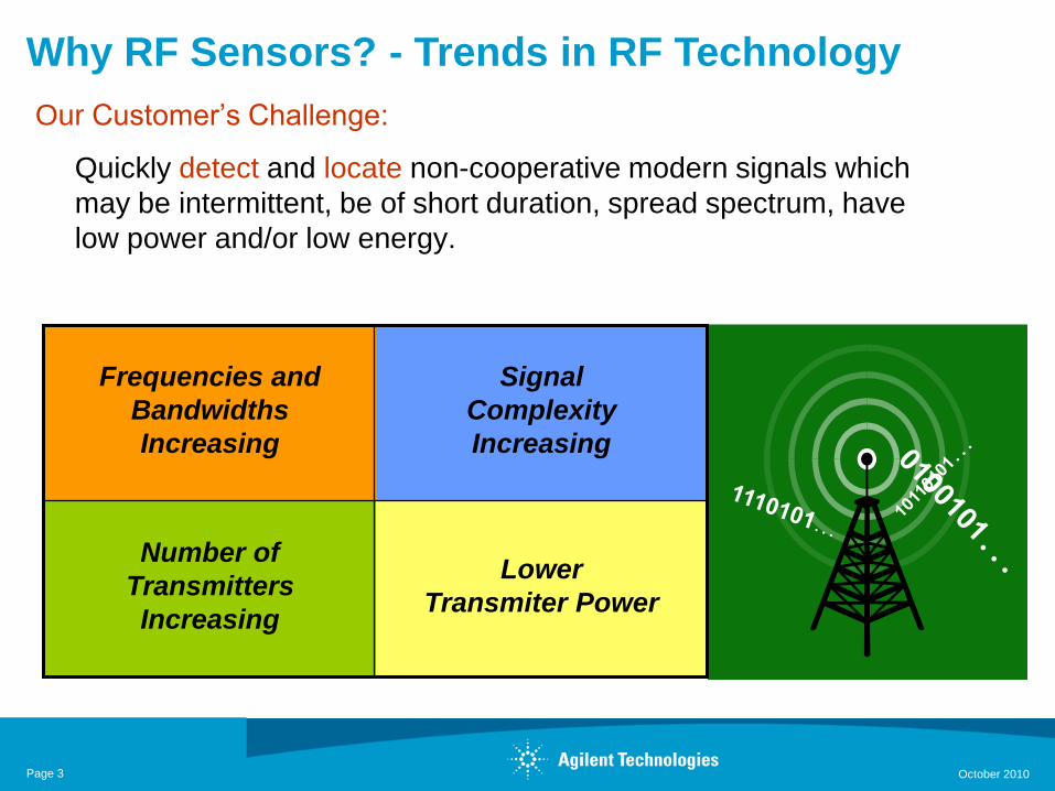
Why RF Sensors? - Trends in RF Technology
Page 3
Our Customer’s Challenge:
Quickly detect and locate non-cooperative modern signals which
may be intermittent, be of short duration, spread spectrum, have
low power and/or low energy.
Frequencies and
Bandwidths
Increasing
Signal
Complexity
Increasing
Number of
Transmitters
Increasing
Lower
Transmiter Power
October 2010
Creating Sensor Networks with the N6841A
S800 Module 305
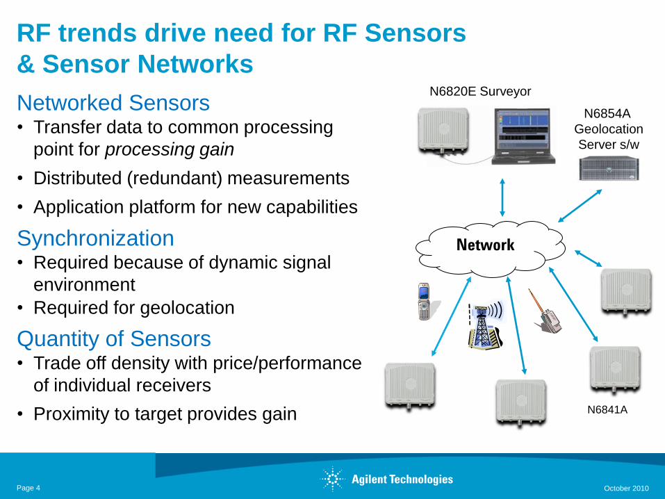
RF trends drive need for RF Sensors
& Sensor Networks
Networked Sensors• Transfer data to common processing
point for processing gain
• Distributed (redundant) measurements
• Application platform for new capabilities
Synchronization• Required because of dynamic signal
environment
• Required for geolocation
Quantity of Sensors• Trade off density with price/performance
of individual receivers
• Proximity to target provides gain
Page 4
Network
N6854A
Geolocation
Server s/w
N6820E Surveyor
N6841A
October 2010
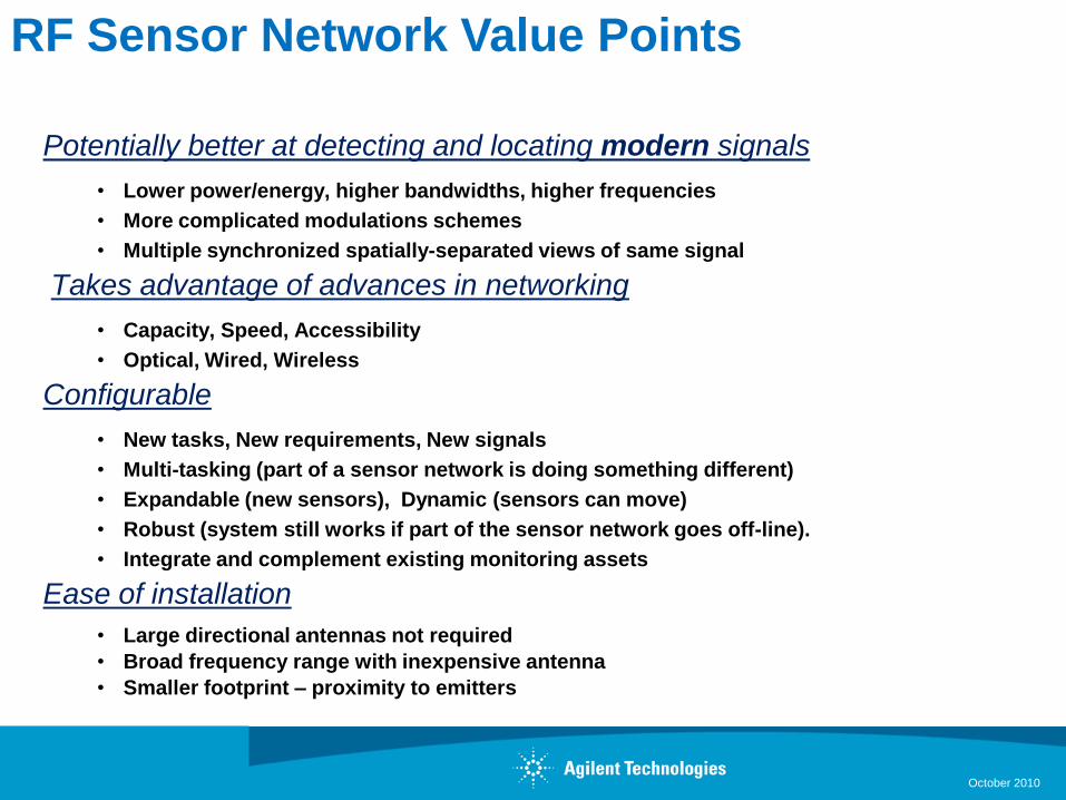
Potentially better at detecting and locating modern signals
• Lower power/energy, higher bandwidths, higher frequencies
• More complicated modulations schemes
• Multiple synchronized spatially-separated views of same signal
Takes advantage of advances in networking
• Capacity, Speed, Accessibility
• Optical, Wired, Wireless
Configurable
• New tasks, New requirements, New signals
• Multi-tasking (part of a sensor network is doing something different)
• Expandable (new sensors), Dynamic (sensors can move)
• Robust (system still works if part of the sensor network goes off-line).
• Integrate and complement existing monitoring assets
Ease of installation
• Large directional antennas not required
• Broad frequency range with inexpensive antenna
• Smaller footprint – proximity to emitters
RF Sensor Network Value Points
October 2010
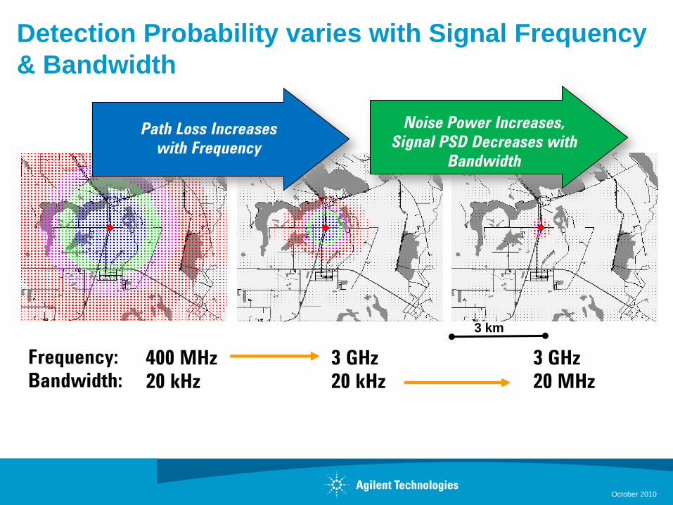
Detection Probability varies with Signal Frequency
& Bandwidth
400 MHz
20 kHz
3 GHz
20 kHz
3 GHz
20 MHz
Frequency:
Bandwidth:
Noise Power Increases,
Signal PSD Decreases with
Bandwidth
Path Loss Increases
with Frequency
3 km
October 2010
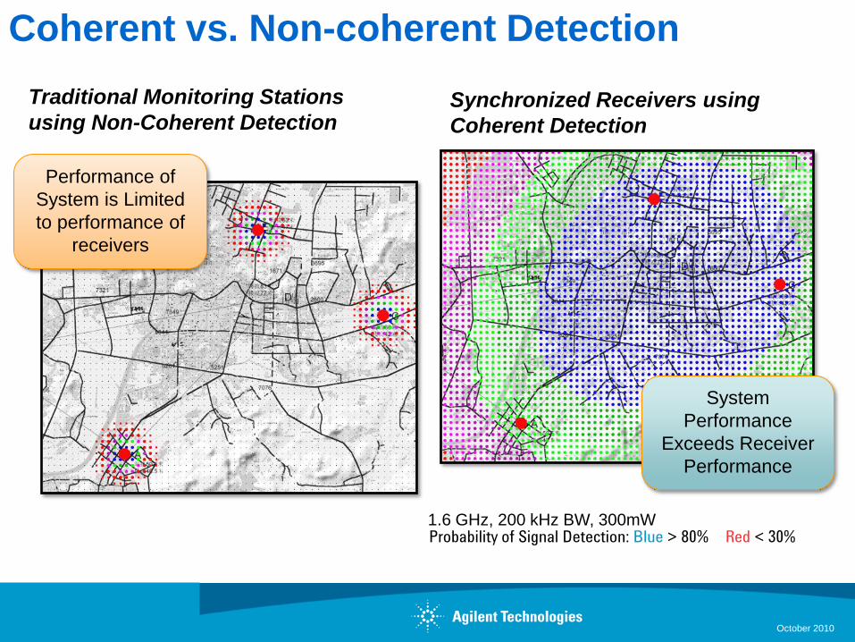
Coherent vs. Non-coherent Detection
Probability of Signal Detection: Blue > 80% Red < 30%
Synchronized Receivers using
Coherent Detection
Traditional Monitoring Stations
using Non-Coherent Detection
1.6 GHz, 200 kHz BW, 300mW
Performance of
System is Limited
to performance of
receivers
System
Performance
Exceeds Receiver
Performance
October 2010
Creating Sensor Networks with the N6841A
S800 Module 305
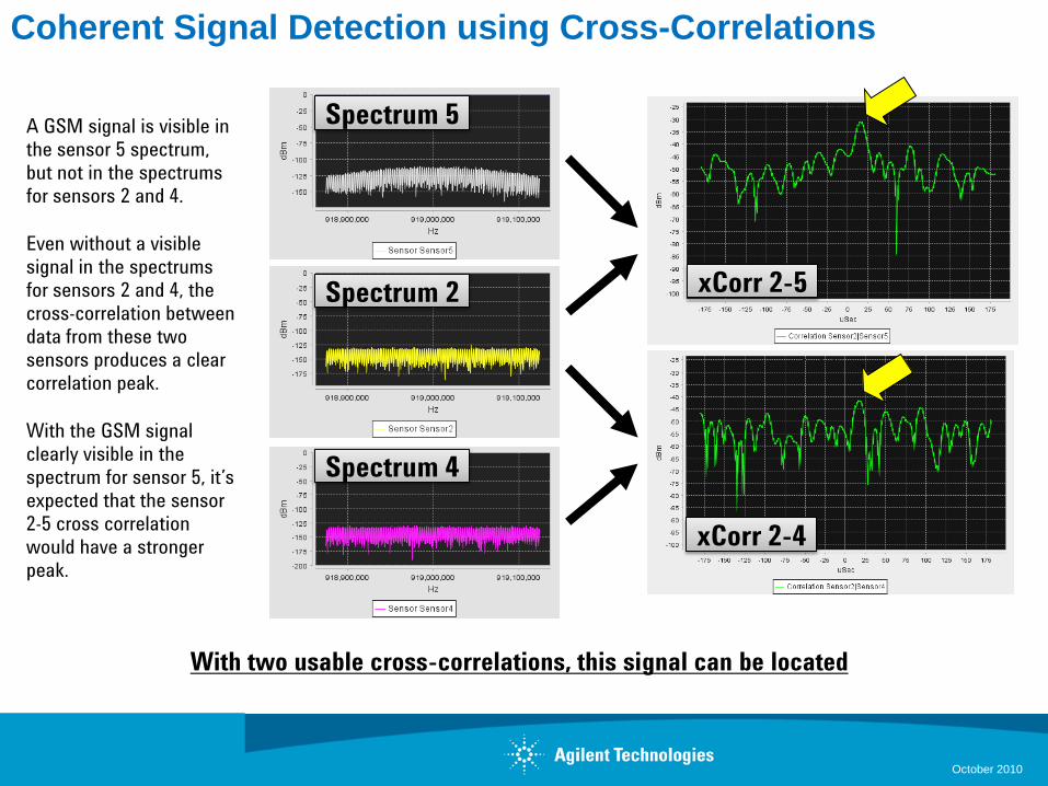
Coherent Signal Detection using Cross-Correlations
A GSM signal is visible in
the sensor 5 spectrum,
but not in the spectrums
for sensors 2 and 4.
Even without a visible
signal in the spectrums
for sensors 2 and 4, the
cross-correlation between
data from these two
sensors produces a clear
correlation peak.
With the GSM signal
clearly visible in the
spectrum for sensor 5, it’s
expected that the sensor
2-5 cross correlation
would have a stronger
peak.
Spectrum 5
Spectrum 2
Spectrum 4
xCorr 2-5
xCorr 2-4
With two usable cross-correlations, this signal can be located
October 2010
Creating Sensor Networks with the N6841A
S800 Module 305
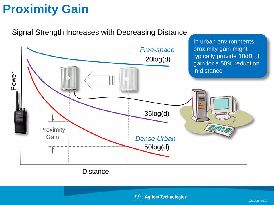
Proximity GainP
ow
er
Distance
20log(d)
35log(d)
50log(d)
Signal Strength Increases with Decreasing DistanceIn urban environments
proximity gain might
typically provide 10dB of
gain for a 50% reduction
in distance
Proximity
Gain
Free-space
Dense Urban
October 2010
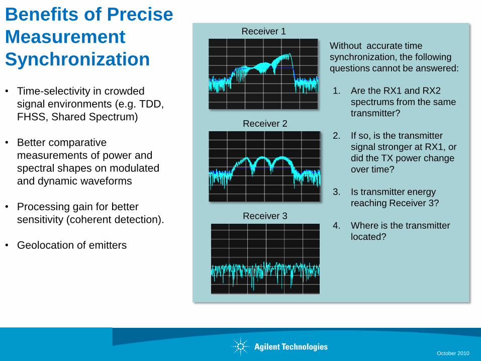
Benefits of Precise
Measurement
Synchronization
• Time-selectivity in crowded
signal environments (e.g. TDD,
FHSS, Shared Spectrum)
• Better comparative
measurements of power and
spectral shapes on modulated
and dynamic waveforms
• Processing gain for better
sensitivity (coherent detection).
• Geolocation of emitters
Receiver 1
Receiver 2
Without accurate time
synchronization, the following
questions cannot be answered:
1. Are the RX1 and RX2
spectrums from the same
transmitter?
2. If so, is the transmitter
signal stronger at RX1, or
did the TX power change
over time?
3. Is transmitter energy
reaching Receiver 3?
4. Where is the transmitter
located?
Receiver 3
October 2010
Sensor Network Deployment Considerations
Measurement Environment
• Outdoor rural, urban or indoor
Sensor Density & Geometry
• Number of sensors –site options
• Accuracy Requirements
• Detection of weak signals
• Multi-path
Sensor receiver & antenna specifications
• Performance versus quantity tradeoff
System time coherency
• Nanoseconds of timing jitter for best accuracy
Network backhaul
• Available bandwidth
• Traffic & network management
October 2010
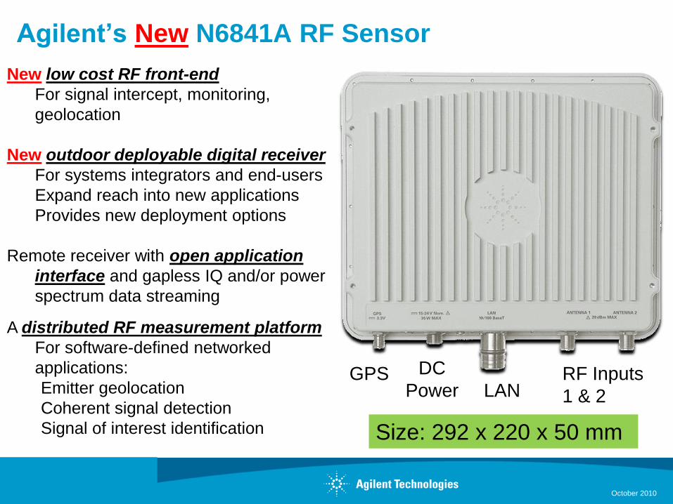
Agilent’s New N6841A RF Sensor
New low cost RF front-end
For signal intercept, monitoring,
geolocation
New outdoor deployable digital receiver
For systems integrators and end-users
Expand reach into new applications
Provides new deployment options
Remote receiver with open application
interface and gapless IQ and/or power
spectrum data streaming
A distributed RF measurement platform
For software-defined networked
applications:
Emitter geolocation
Coherent signal detection
Signal of interest identification
LANRF Inputs
1 & 2
DC
PowerGPS
Size: 292 x 220 x 50 mm
October 2010
October 2010
N6841A RF Features
• 20 to 6000 MHz coverage
• 3rd party up/down converters available
• 20 MHz information bandwidth
• Co-location of receiver with antenna minimizes RF coax
length and signal loss
• 2 RF inputs for multiple antennas
• Software auto-selects port based on frequency (user specified)
• Front end pre-selection filters
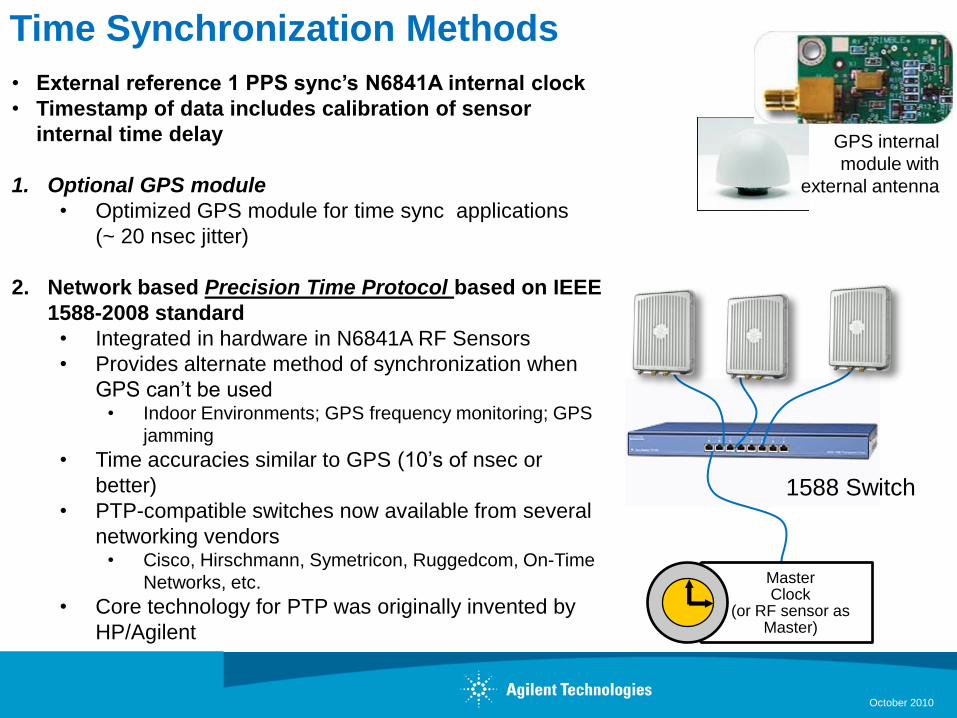
Time Synchronization Methods
• External reference 1 PPS sync’s N6841A internal clock
• Timestamp of data includes calibration of sensor
internal time delay
1. Optional GPS module
• Optimized GPS module for time sync applications
(~ 20 nsec jitter)
2. Network based Precision Time Protocol based on IEEE
1588-2008 standard
• Integrated in hardware in N6841A RF Sensors
• Provides alternate method of synchronization when
GPS can’t be used• Indoor Environments; GPS frequency monitoring; GPS
jamming
• Time accuracies similar to GPS (10’s of nsec or
better)
• PTP-compatible switches now available from several
networking vendors• Cisco, Hirschmann, Symetricon, Ruggedcom, On-Time
Networks, etc.
• Core technology for PTP was originally invented by
HP/Agilent
1588 Switch
MasterClock
(or RF sensor as Master)
GPS internal
module with
external antenna
October 2010
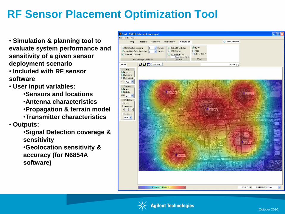
RF Sensor Placement Optimization Tool
October 2010
• Simulation & planning tool to
evaluate system performance and
sensitivity of a given sensor
deployment scenario
• Included with RF sensor
software
• User input variables:
•Sensors and locations
•Antenna characteristics
•Propagation & terrain model
•Transmitter characteristics
• Outputs:
•Signal Detection coverage &
sensitivity
•Geolocation sensitivity &
accuracy (for N6854A
software)
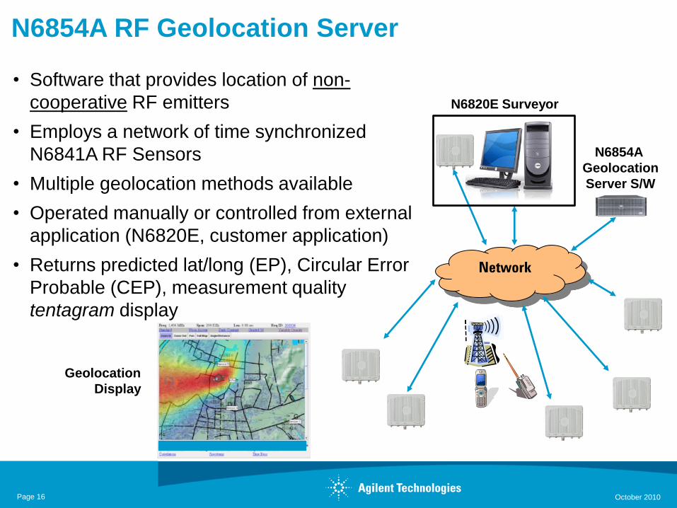
N6854A RF Geolocation Server
• Software that provides location of non-
cooperative RF emitters
• Employs a network of time synchronized
N6841A RF Sensors
• Multiple geolocation methods available
• Operated manually or controlled from external
application (N6820E, customer application)
• Returns predicted lat/long (EP), Circular Error
Probable (CEP), measurement quality
tentagram display
Geolocation
Display
Network
N6854A
Geolocation
Server S/W
N6820E Surveyor
Page 16 October 2010
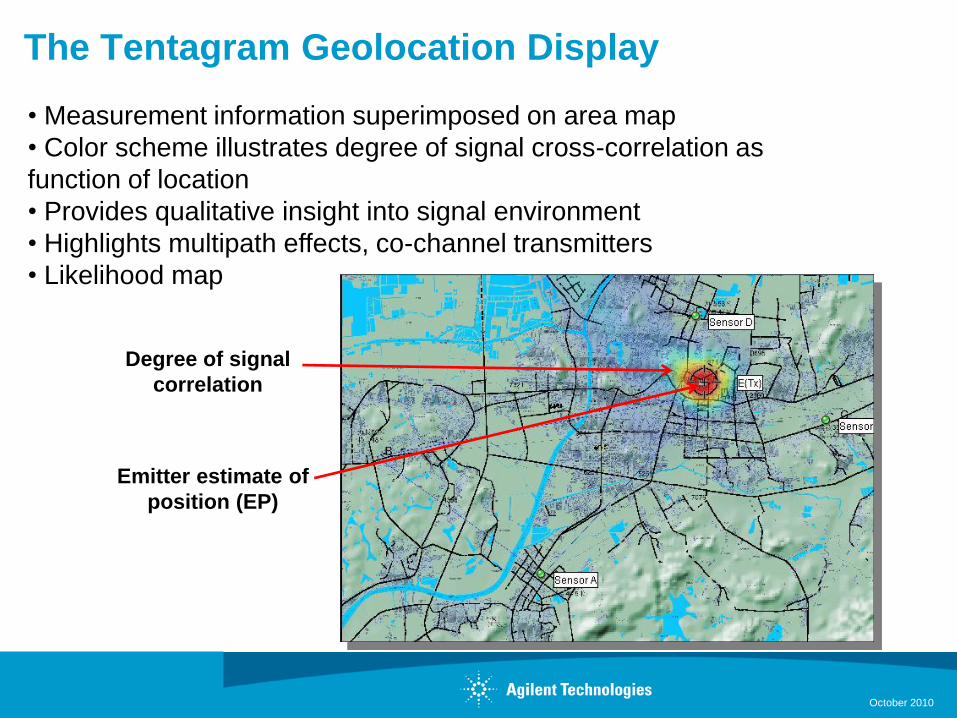
The Tentagram Geolocation Display
October 2010
• Measurement information superimposed on area map
• Color scheme illustrates degree of signal cross-correlation as
function of location
• Provides qualitative insight into signal environment
• Highlights multipath effects, co-channel transmitters
• Likelihood map
Degree of signal
correlation
Emitter estimate of
position (EP)
Geolocation Methods Available
• Time Difference of Arrival
• Measure Time of arrival of signal feature at 3 or more sensors
• Time difference between sensors forms hyperbolic of position
• Intersection of hyperbolic is EP
• Relative Signal Strength Amplitude Ratio
• Compares signal strength at 4 or more sensors
• Amplitude ratio between sensors forms circle of position
• Intersection of circles is EP
• Hybrid
• Combines both techniques in an adaptive approach
• Different weighting of variables depending on measurement environment
October 2010
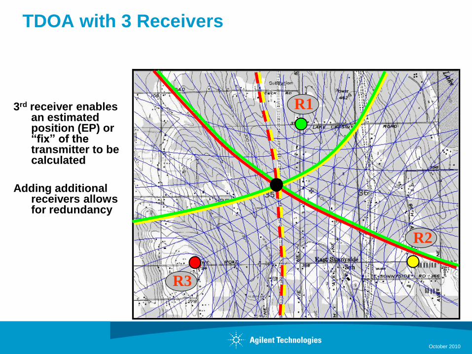
TDOA with 3 Receivers
3rd receiver enables an estimated position (EP) or “fix” of the transmitter to be calculated
Adding additional receivers allows for redundancy
R1
R3
R2
October 2010
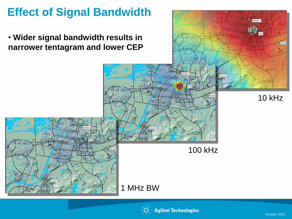
Effect of Signal Bandwidth
1 MHz BW
100 kHz
10 kHz
• Wider signal bandwidth results in
narrower tentagram and lower CEP
October 2010
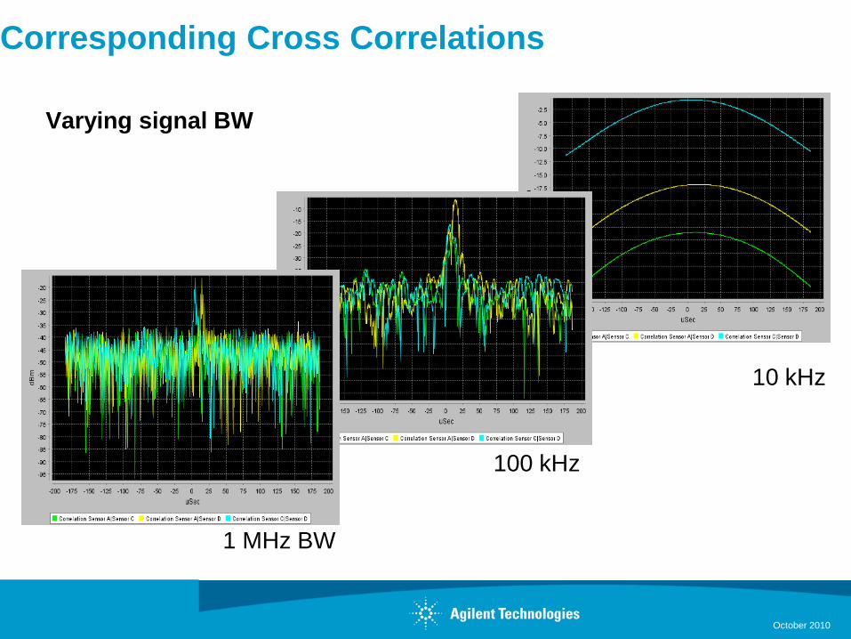
Corresponding Cross Correlations
Varying signal BW
1 MHz BW
100 kHz
10 kHz
October 2010
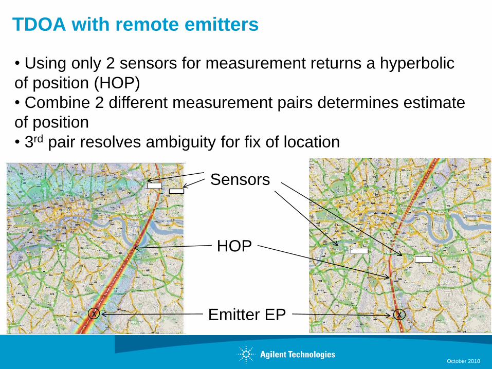
TDOA with remote emitters
October 2010
• Using only 2 sensors for measurement returns a hyperbolic
of position (HOP)
• Combine 2 different measurement pairs determines estimate
of position
• 3rd pair resolves ambiguity for fix of location
Emitter EP
Sensors
HOP
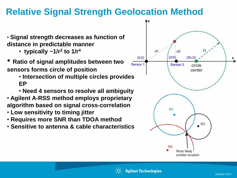
Relative Signal Strength Geolocation Method
October 2010
• Signal strength decreases as function of
distance in predictable manner
• typically ~1/r2 to 1/r4
• Ratio of signal amplitudes between two
sensors forms circle of position
• Intersection of multiple circles provides
EP
• Need 4 sensors to resolve all ambiguity
• Agilent A-RSS method employs proprietary
algorithm based on signal cross-correlation
• Low sensitivity to timing jitter
• Requires more SNR than TDOA method
• Sensitive to antenna & cable characteristics
Hybrid Geolocation Method
• Adaptive technique that combines A-TDOA and A-RSS
algorithms
• Input parameters include signal power, measurement
bandwidth and sensor spacing
• Weighs algorithms using proprietary technique for optimum
results
October 2010
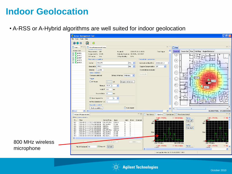
Indoor Geolocation
• A-RSS or A-Hybrid algorithms are well suited for indoor geolocation
800 MHz wireless
microphone
October 2010
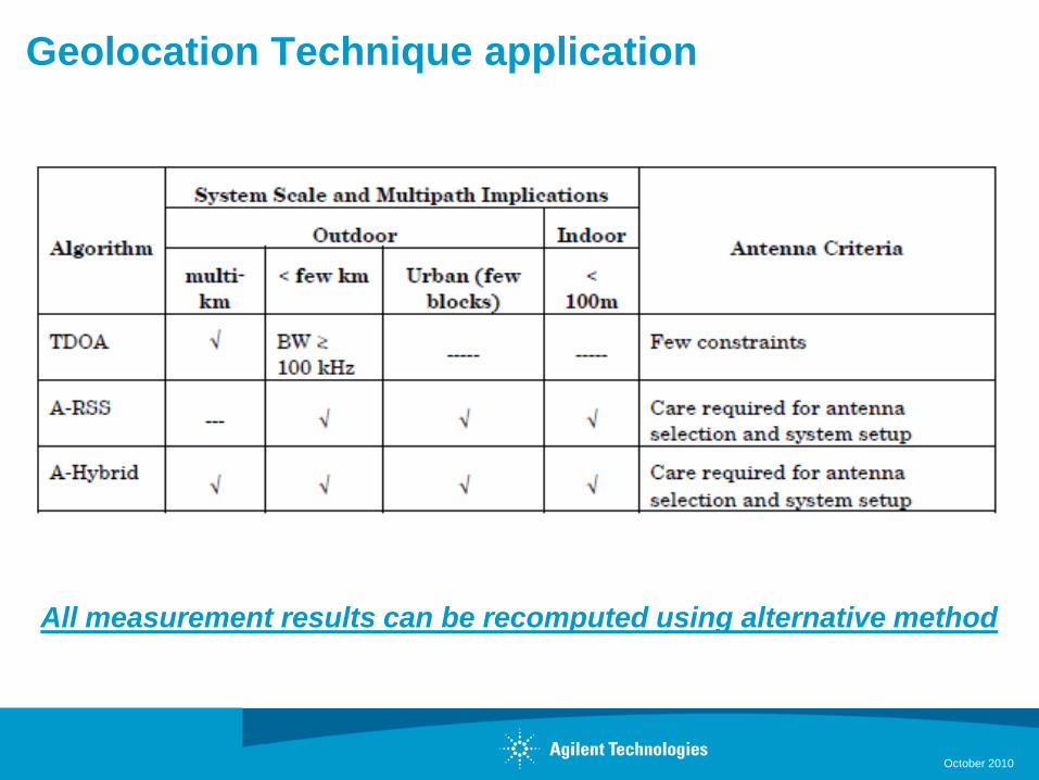
Geolocation Technique application
October 2010
All measurement results can be recomputed using alternative method

Creating Sensor Networks with the N6841A
S800 Module 305
Geolocation Visualization Tools
Software includes utility
to export geolocation
results in KML format
October 2010
October 2010
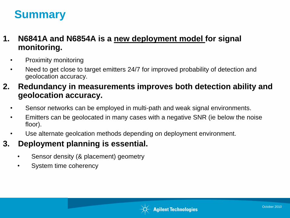
Summary
1. N6841A and N6854A is a new deployment model for signal monitoring.
• Proximity monitoring
• Need to get close to target emitters 24/7 for improved probability of detection and geolocation accuracy.
2. Redundancy in measurements improves both detection ability and geolocation accuracy.
• Sensor networks can be employed in multi-path and weak signal environments.
• Emitters can be geolocated in many cases with a negative SNR (ie below the noise floor).
• Use alternate geolcation methods depending on deployment environment.
3. Deployment planning is essential.
• Sensor density (& placement) geometry
• System time coherency

Creating Sensor Networks with the N6841A
S800 Module 305
Q & A
October 2010


![Error Control Coding in Low-Power Wireless Sensor ...hcdc/Library/HowSchIni2006.pdfMinimizing transmitted RF power is the key to energy-efficient wireless sensor networks [1–3]](https://img.pdfslide.us/doc/110x75/5adbb9207f8b9a52528ea23f/error-control-coding-in-low-power-wireless-sensor-hcdclibraryhowschini2006pdfminimizing.jpg)