Embed Size (px)
Citation preview

RF Mogul
Satellite Dish Controller
Model: SDC1
Manual
07 July 2012


i
Index
Quick Start! 1 (Start Here!)
SDC1 – Satellite Dish Controller – Features 1
Minimum required Hardware 2
Wiring Controller to the Antenna 3 (simplified)
Using the Controller to move the Dish 4 (install and service)
HTML
Configuring the SDC1 Network - HTML 5 (LAN port)
Dish (Sensors) Calibration - HTML 7 (!!! IMPORTANT !!!)
Search Settings Page - HTML 8 (Modem or SNG)
System Status Page - HTML 9 (Normal Operation Screen)
RF Settings – LNB Configuration - HTML 10 (LNB and BUC Settings)
System Diagnostics Page – HTML 11 (service and repair)
Front Panel
AC Power – Front Panel 12 (HPA/BUC Kill Switch)
Power, Search, and Stow – Front Panel 12 (Normal Operation Buttons)
LCD Display Control – Front Panel 13 (Functions and Settings)
Manual Motor Control – Front Panel 13 (Manual JOG Control)
Front Panel Graphic Display
Normal Status Display 14 (Main Display Page)
Menu Functions 15 (Function Control)
Satellite Select Drop Down 15 (Satellite Table List)
Manual Location – GPS 15 (Location Control)
Network Settings (Information) 16 (IT Use Only)
Network – Restore Defaults 16 (Consult IT!)
FLASH (USB) Import and Export 17 (Advanced Setup)
Sat Tables Import and Export 17 (Advanced Setup)
Configuration Import and Export 17 (Advanced Setup)
FCC and Safety Compliance 18 (Statements)
SDC1 Controller Specifications 19 (Spec Sheet)
End of Document 20
1
SDC1 - Satellite Dish Controller - Features
Fast and easy Install and Setup
2RU 19” Rack Mount Chassis
Fully Controllable through HTML on any Browser
Front Panel 3.5” TFT LCD Display 320 X 240 pixels
Full Feature Front Panel Operation
Unlimited Satellite Drop Down Box
Automatic Dish Calibration
Automatic Modem Configuration
Automatic Satellite Table Configuration (GPS based)
Worldwide Satellite Table Installed (editable)
Manual Motor Jog Controls (all Axis)
Identification methods, DVBS, DVB-S2, and NID
USB Flash Upgrade Port on Front Panel
USB Flash direct Configuration (no computer connection required)
Quick Start!
Following the Instructions located on Pages 2 through 9 without skipping any pages will allow
you to quickly get the SDC1 Satellite dish Controller mated to the General Dynamics C1xxM
Antenna Positioner.
These pages will guide you through the;
Minimum required hardware
Wiring the SDC1 Controller to the Antenna Positioner
Moving the Dish using the SDC1 Controller for Installation.
Configuring the SDC1 Controller Network Settings.
Calibrating the Dish Sensors.
Configuring the Search Settings.
Finding the First Satellite(s).
2
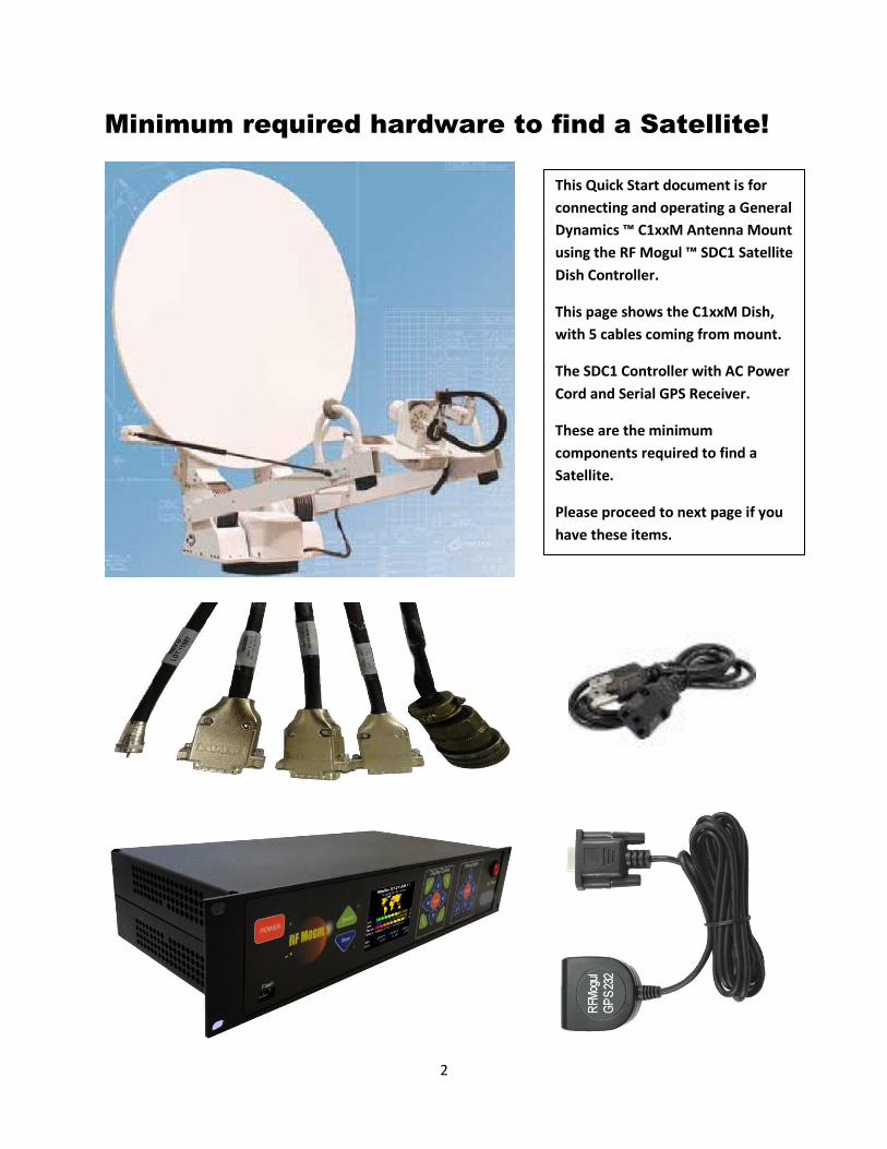
Minimum required hardware to find a Satellite!
This Quick Start document is for
connecting and operating a General
Dynamics ™ C1xxM Antenna Mount
using the RF Mogul ™ SDC1 Satellite
Dish Controller.
This page shows the C1xxM Dish,
with 5 cables coming from mount.
The SDC1 Controller with AC Power
Cord and Serial GPS Receiver.
These are the minimum
components required to find a
Satellite.
Please proceed to next page if you
have these items.
3
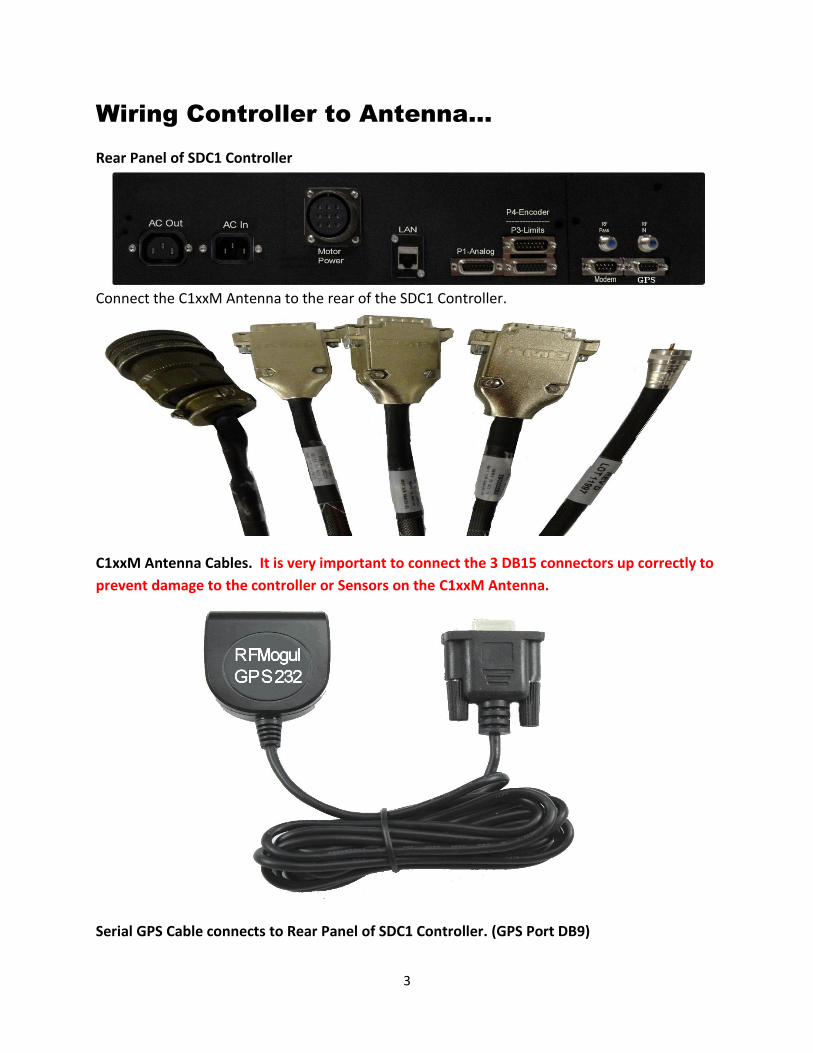
Wiring Controller to Antenna…
Rear Panel of SDC1 Controller
Connect the C1xxM Antenna to the rear of the SDC1 Controller.
C1xxM Antenna Cables. It is very important to connect the 3 DB15 connectors up correctly to
prevent damage to the controller or Sensors on the C1xxM Antenna.
Serial GPS Cable connects to Rear Panel of SDC1 Controller. (GPS Port DB9)

4
Other connections:
AC Power Cord
LAN Cable to Router or Switch
Optional Modem Connections:
Modem RF Input Cable (RG6)
Modem Serial Cable (LAN preferred)
Optional HPA (BUC) Connections
AC Out to control High Powered Amplifiers (Switched Port)
Using the Controller to install the C1xxM …
The C1xxM Antenna Positioner can be moved using the SDC1 Controller once all cables are
connected and power is applied to the SDC1 Controller.
Front Panel VGA LCD Display Front Panel Manual Motor
Using the Manual Motor Controls the C1XXM Antenna Positioner can be moved to facilitate
installation or service.
It is very important when moving the C1XXM for the first time that a spotter is close to the
Dish for assistance.
Press the RED Manual button in the center to activate Manual Motor control. The Red LED
will illuminate. The EL, AZ and SK commands are now active. NOTE: Elevation must be
raised above 0 degrees (74 degrees from stowed) before Azimuth can be moved.

5
Configuring the SDC1 Network …
The SDC1 Controller can be configured through the LAN port (RJ45 Cat 5e) located on the back
of the Controller or by importing a modified NETCFG file through the front Flash (USB) port.
When using the LAN Port, with the DHCP enabled the default IP Address is 169.1.1.254. This
port can auto detect both normal and crossover LAN cables. Because of this you can directly
connect your PC to the LAN port of the SDC1 and use IP Address 169.1.1.254 to set up the
controller. You can also enter rfmsdc on your browser address line to access the SDC1
Controller.
If the IP Address is unknown you can find the current IP Address by accessing the Network
Menu on the Front Panel Display. From the Display Control press Menu, Down Arrow, then
select, to view the current Network Settings.
Front Panel VGA LCD Display Front Panel Display Control
From the Network Menu you can Restore Defaults if the current IP Information is not usable
or if the User Name and Password have changed and you cannot access the HTML Network
Settings Page.
Network Settings can be modified in the SDC1 HTML Network Settings Page. The default
username is admin and the password is password. To access the SDC1 HTML you will be
required to enter the username and password. These can be removed or changed once you
have accessed the Network Settings Page.

6
The SDC1 Controller is usually connected through a Router or Switch. Enter the proper IP
settings for the network that is in use. Consult with your IT Department for proper network
configuration.
If you are using Firmware Version 1.4 (July 2012) or newer you can now modify the current
network settings by exporting, modifying, and importing modified NETCFG files through the
front Flash (USB) port.
See the SDC1 Advanced Configuration and Setup Manual for additional information.
Network Settings Page
Once the Network Settings have been modified press the Apply button to save.
Remember you can always restore default IP settings from the SDC1 Controller Front Panel.
The SDC1 Controller will return to the Main System Status Page.
7
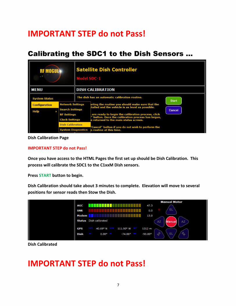
IMPORTANT STEP do not Pass!
Calibrating the SDC1 to the Dish Sensors …
Dish Calibration Page
IMPORTANT STEP do not Pass!
Once you have access to the HTML Pages the first set up should be Dish Calibration. This
process will calibrate the SDC1 to the C1xxM Dish sensors.
Press START button to begin.
Dish Calibration should take about 3 minutes to complete. Elevation will move to several
positions for sensor reads then Stow the Dish.
Dish Calibrated
IMPORTANT STEP do not Pass!

8
HTML Search Settings Page …
Search Settings Page
Set up Modem parameters as required (contact your NMC/NOC for more information). If no
modem is connected select None.
The correct satellite longitude is automatically selected when a Hughes™ or iDirect™ Modem
is commissioned properly. You will need to consult your NOC/NMC for proper polarization
settings for the iDirect™ Modem.
Unless you are using multiple LNBs or multiple Local Oscillators, leave LNB0 as default the
default selection for Search, Target, and Modem LNBs.
Default Satellite is set to Last Selected. See the SDC1 Advanced Configuration and Setup
Manual for additional information.
Location Method is set as GPS is active (default). If a GPS is not connected to the Controller
you can select Manual and input the current Latitude and Longitude.

9
HTML Main Status Page …
System Status (default) Page
After completing the quick steps above the SDC1 Controller is ready to Find Satellite.
Select the proper Satellite Longitude/Polarity/Name from the drop down menu above then
press the Search (Arrow) Button. The dish will begin a search for the selected Satellite.
Typical Search times will vary from 4 to 8 Minutes. If a Modem is connected additional time
will be required for TX timing lock.

10
ADVANCED RF Settings Page …
RF Settings Page
Most Mobile Satellite Antenna Systems are configured with one LNB and one Transmitter
(BUC). The default condition is BUC Polarity set to Vertical and LNB Polarity set to Horizontal.
These conditions are based on viewing the BUC and LNB when the Dish Skew Angle is at 0
degrees.
If additional LNBs are used the SDC1 Controller can be configured to automatically switch and
operate them as required in Search, Identification, and Modem use.
Each LNB can be set up to be activated by Voltage, 22KHz Tones, or DiSEqC commands. If the
LNB can see additional polarities electrically then multiple Voltages can be selected.
It is important to set the LO Frequency and the RF Band (Min to Max) for proper searching.
NOTE: Additional LNBs can also be set off Center Focus and Azimuth and Elevation Offsets
can be set to locate their position based on Center Feed Focus. (This can be helpful when
wanting to switch to a different RF Band (C, Ku, Ka, X)).

11
ADVANCED System Diagnostics Page …
System Diagnostics Page
Used as a Diagnostic and Service tool the System Diagnostics Page shows the real time
conditions of the Dish/Mount Sensors, Counters and Limit Switches.
Using this Page all sensors, pots, counters, and switches can be replaced and calibrated.
GPS, LNB Voltages and the External AC Power port are also displayed.
Contact your system integrator or Mount Manufacture for assistance in service.
Important! Do not run the Dish in normal operation from this page. For Service Only!

12
Front Panel Operations…
The SDC1 Controller can be operated from the Front Panel.
Besides the ability to Search (for a satellite) and Stow the Dish, the customer (user) can make
Satellite Selections, Manually Input LAT/LON Location, Import and Export Satellite Tables,
and manually move the Satellite Dish.
All of this is accomplished using the 3.5” Color LCD Graphic Display and Tactile Membrane
Switches.
Front Panel AC Power…
Front Panel Power, Search, Stow, …
The Flash Connector will accept USB2.0 Memory devices. This port is used to upgrade the
Controller Firmware, Sat Tables, and Configuration Files.
AC Power Switch controls 100 – 240 VAC Power to the SDC1
Controller.
This Switch can be used as a HPA/BUC Kill Switch if needed.
In normal operation we recommend shutting down the SDC1
Controller by first using the soft POWER switch in the top left
corner of the Front Panel before switching OFF the AC power
switch.
Gold Label displays the Model and Serial Number of the
Controller.
The Power Switch shuts down the
internal DC Power to the PCBs
and keeps the unit in a low power
condition.
It is recommended to power
down the SDC1 Controller using
this Button first before shutting
off the AC Power rocker switch.

13
The Search Button will initiate an Antenna Search for the Satellite Name displayed at the Top
of the LCD Screen. (This Satellite Name can be changed using the Menu and changing the
Satellite Name in the Drop Down Box).
The Stow Button will lower the Antenna back into a Travel Position.
Front Panel Display and Motor Controls…
The Display Control includes all of the Buttons used to navigate the LCD Graphic Display
Menu’s.
When pressed, the Menu Button will change the LCD Graphic Display to the MENU Mode.
This Menu will allow the user to change the Search Satellite, update Latitude and Longitude
Location when GPS is not available, view current Network configuration, and reset the
Network to Default settings, and Import or Export Satellite Tables when updating is
necessary.
When the Manual Button is pressed the RED LED will illuminate indicating the Satellite
Antenna Positioner can now be manually moved in all three axis, Azimuth, Elevation, and
Skew (Polarization). This allows the user additional flexibility when trying to position the
antenna in difficult situations.
IMPORTANT!!! Even though the SDC1 Controller has built in safeguards to prevent the user
from causing damage to the Antenna Positioner during Manual Motor movement, caution
should always be taken when moving the Antenna to prevent injury or damage to persons
and equipment.
14
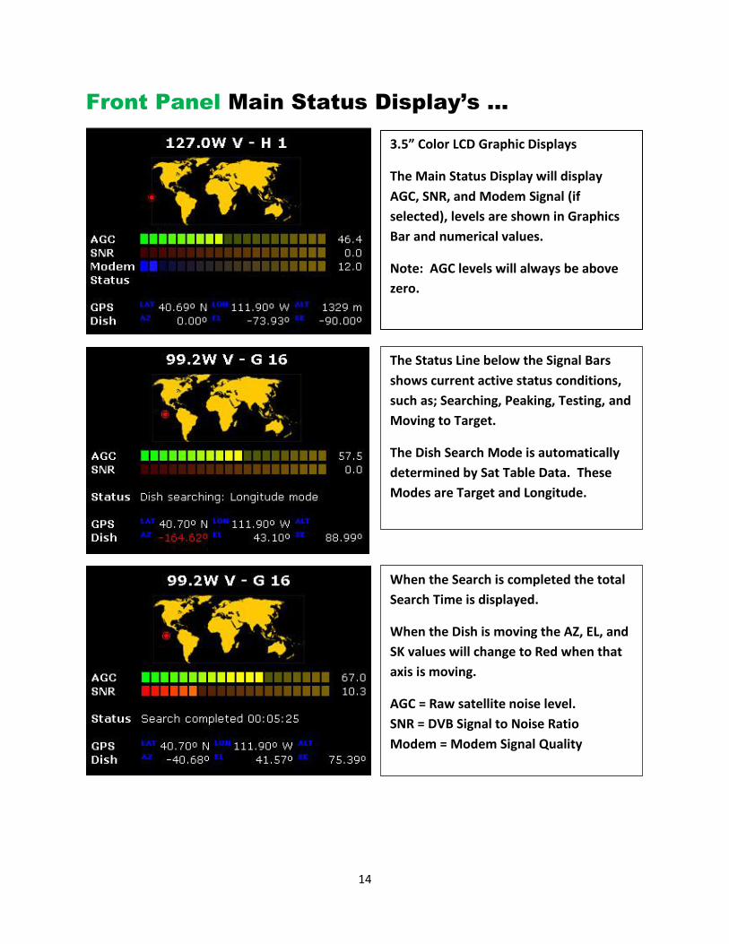
Front Panel Main Status Display’s …
3.5” Color LCD Graphic Displays
The Main Status Display will display
AGC, SNR, and Modem Signal (if
selected), levels are shown in Graphics
Bar and numerical values.
Note: AGC levels will always be above
zero.
The Status Line below the Signal Bars
shows current active status conditions,
such as; Searching, Peaking, Testing, and
Moving to Target.
The Dish Search Mode is automatically
determined by Sat Table Data. These
Modes are Target and Longitude.
When the Search is completed the total
Search Time is displayed.
When the Dish is moving the AZ, EL, and
SK values will change to Red when that
axis is moving.
AGC = Raw satellite noise level.
SNR = DVB Signal to Noise Ratio
Modem = Modem Signal Quality

15
Front Panel Menu Selections
Satellite
Up and Down Arrows
Highlight Satellite/Polarity
Press Select
Press Exit
The Main Status Screen will show the
new Satellite and Polarity.
Press Search to Find that Satellite
Function Menu
Press Menu
Up and Down Arrows
Select Function
(Satellite, Location, Network, or Flash)
Press Select
Location
Up and Down Arrows will change the
Box entry or numerical value.
Left and Right Arrows will advance to
the next Box.
Enter will save the changes.
Exit will jump to Status Display.

16
Location - Manual selected
Used when GPS is not available.
Up and Down Arrows will change the
numerical values.
Left and Right Arrows will advance to
next Box.
Enter will save the changes.
Exit will jump to Status Display.
Network
Press Select
Used to allow IT a quick view of
Network settings.
Cancel, Enter, or Select to exit without
changing Network Settings.
Exit returns to Status Screen.
Network - Default Settings
Use up and down arrows to select
Restore Defaults.
Press Enter to Restore Defaults.
Warning this will change the current
network settings!

17
Configuration Files import and export like Sat Table Files. Exported Files can be edited then
re-imported into the SDC1 Controller. Always BACK UP the Exported files in case of
accidental corruption of edited files!
Flash Menu
The Flash Menu works with a USB
Memory Device plugged into the
Front Panel FLASH (USB) port.
Satellite Tables and Configuration
Files may be Imported or Exported
using this operation.
Files will be placed into the root
directory of the USB Device.
Flash Import
To Import, the Satellite Table must be
named SATTBL.XML and should be placed
in the Root Directory of the USB Device.
Insure USB Stick is in the FLASH port.
Use the Up and Down Arrows
Select Import Satellite Table.
Wait for Busy Indicator to expire.
Sat Table is imported.
Flash Export
To Export the Satellite Table. Insure USB
Stick is in the FLASH port.
Use the Up and Down Arrows
Select Export Satellite Table.
Wait for Busy Indicator to expire.
The Satellite Table has been exported to
the Root Directory of the USB Device as
SATTBL.XML and is located the Root
Directory of the USB Device.
18
FCC and Safety Compliance
Federal Communications Commission (FCC) Statement
Note: This equipment has been tested and found to comply with the limits for a Class A digital device, pursuant to Part 15 of the FCC Rules. These limits are designed to provide reasonable protection against harmful interference when the equipment is operated in a commercial environment. This equipment generates, uses, and can radiate radio frequency energy and, if not installed and used in accordance with the instruction manual, may cause harmful interference to radio communications. Operation of this equipment in a residential area is likely to cause harmful interference, in which case the user will be required to correct the interference at his own expense.
Properly shielded and grounded cables and connectors must be used in order to meet FCC emission limits. RF Mogul LLC is not responsible for any radio or television interference caused by using other than recommended cables and connectors or by unauthorized changes or modifications to this equipment. Unauthorized changes or modifications could void the user's authority to operate the equipment.
This device complies with Part 15 of the FCC rules. Operation is subject to the following two conditions: (1) this device may not cause harmful interference, and (2) this device must accept any interference received, including interference that may cause undesired operation.
This device complies with FCC Section 15.103(a)(d)
1. Digital devices used EXCLUSIVELY in any transportation vehicle including motor
vehicles, aircraft, and watercraft.
2. Digital devices used EXCLUSIVELY to move something by converting electrical
energy into motion.
Responsible Party: RF Mogul LLC 3604 S. Via Terra Street Salt Lake City, Utah 84115
19
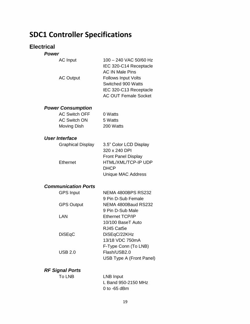
SDC1 Controller Specifications
Electrical
Power
AC Input 100 – 240 VAC 50/60 Hz
IEC 320-C14 Receptacle
AC IN Male Pins
AC Output Follows Input Volts
Switched 900 Watts
IEC 320-C13 Receptacle
AC OUT Female Socket
Power Consumption
AC Switch OFF 0 Watts
AC Switch ON 5 Watts
Moving Dish 200 Watts
User Interface
Graphical Display 3.5” Color LCD Display
320 x 240 DPI
Front Panel Display
Ethernet HTML/XML/TCP-IP UDP
DHCP
Unique MAC Address
Communication Ports
GPS Input NEMA 4800BPS RS232
9 Pin D-Sub Female
GPS Output NEMA 4800Baud RS232
9 Pin D-Sub Male
LAN Ethernet TCP/IP
10/100 BaseT Auto
RJ45 Cat5e
DiSEqC DiSEqC/22KHz
13/18 VDC 750mA
F-Type Conn (To LNB)
USB 2.0 Flash/USB2.0
USB Type A (Front Panel)
RF Signal Ports
To LNB LNB Input
L Band 950-2150 MHz
0 to -65 dBm

20
F-Type Conn (To LNB)
To Modem LNB Signal Pass Thru
L Band 950-2150 MHz
0 to -65 dBm
F-Type Conn (To Modem)
Antenna Interface
Motor Power AZ, EL, SK (Pol)
Variable Motor 7 to 24 VDC
Up to 9.0 Amps
MS3102A22-20S (Female)
Analog Ports AZ, EL, SK (Pol)
P1 Analog +/- 12VDC Regulated
15 Pin D-Sub Female
Digital Ports AZ, EL Limit Detects
P3 Limits 5 VDC - VCC
15 Pin D-Sub Female
Digital Ports AZ, EL Encoders Counters
P4 Encoders 5 VDC - VCC
15 Pin D-Sub Male
Mechanical
Weight
Lbs. (pounds) 10 Lbs.
Kgs (kilograms) 4.5 kgs
Dimensions
Inches 19L x 8.5D x 3.5H
Centimeters 48.3L x 21.6 x 8.9
2 Rack Units (2RU)
Temperature
Fahrenheit +32 to +158 F
Centigrade 0 to +70 C
Storage Temp
Fahrenheit -30 to +185 F
Centigrade -35 to +85 C
Features
Satellite Identification
DVB-S, DVB-S2, NID (Network Identification)
Stackable Controllers
Use multiple Controllers on same Network
End of Document