Embed Size (px)
Citation preview
RF Energy Harvesting System from Cell Towers in900MHz Band
Mahima ArrawatiaElectrical Engineering Department
Indian Institute of Technology BombayPowai, Mumbai-400076, IndiaEmail: [email protected]
Maryam Shojaei BaghiniElectrical Engineering Department
Indian Institute of Technology BombayPowai, Mumbai-400076, IndiaEmail: [email protected]
Girish KumarElectrical Engineering Departmen
Indian Institute of Technology BombayPowai, Mumbai-400076, IndiaEmail: [email protected]
Abstract—An experimental RF energy harvesting system toharvest energy from cell towers is presented in this paper.An electromagnetically-coupled square microstrip antenna isdesigned and fabricated for deployment in the presented system.Antenna gain of 9.1dB and bandwidth from 877 MHz to 998MHz is achieved. A Schottky diode-based single stage voltagedoubler and six-stage voltage doubler has also been designed andfabricated for DC voltage generation. Measured results show thata voltage of 2.78V is obtained at a distance of 10m from the celltower and a voltage of 0.87V is obtained at a distance of 50m.
I. INTRODUCTION
Available RF energy in the ambient or areas close totransmission towers provides an opportunity to harvest thatenergy. Some of the most prominent sources are FM radiosystems ((88-108 MHz, transmitted power few tens of KW),TV Transmission (180-220 MHz, transmitted power few tensof KW), Cell Tower Transmission (10 to 20 W per carrier),Wi-Fi (2.45GHz, 5.8GHz), AM Transmission (540-1600 KHz,transmitted power few hundred KW) and mobile phones(transmitted power 1W to 2W), etc.
Cell towers can be used as a continuous source of renewableenergy as they transmit 24 hours. In India cell towers transmitin the frequency range of 869- 890 MHz in CDMA, 935-960MHz in GSM 900 and 1810-1880MHz in GSM 1800 bands.It transmits 10 to 20W per carrier; there maybe 3 to 4 carriersand 3 to 4 operators on a single tower or spread over the rooftop of buildings. Gain of the cell tower transmitter antennais typically 17dB. The half power beam width (HPBW) ofthe antenna in horizontal direction maybe between 60o to 90o
and in vertical direction varies between 5oto 10o. Maximumpower is received when the receiver is in the main beam. Forcell site consisting of transmitting towers of GSM900 band,signal strengths are calculated in Table I at various distancesaccording to Friis transmission equation.
Pr = PtGtGr[λ/(4πR)]2 (1)
Where,Pr = Received PowerPt= Transmitted PowerGt= Gain of the transmitted AntennaGr= Gain of the receiver AntennaR= Distance between the transmitter and receiver antennas
TABLE IPOWER RECEIVED FROM CELL TOWERS (GSM 900 BAND)
Distance (m) 200 100 50 10 5Number of Carriers 1 1 1 1 1
Number of Operators 1 1 1 1 1Power Received(mW) 0.13 0.50 6.03 50.28 201.12Power Received(dBm) -9.01 -2.99 7.81 17.01 24.01
Fig. 1. Basic Block Diagram of RF Energy Harvesting System
The gain of the cell tower transmitter antenna is 17dB.Receiver antenna gain is taken as 9dB according to thefabricated microstrip antenna gain. Transmitted power is 20Wfrom the cell towers. Frequency is taken as 950MHz which isapproximately middle value of GSM 900 band.
For full signal strength, a cell phone requires only -69dBmpower. In a radius within 50m from a cell tower, power levelis very high. Such high power levels cause various healthhazards, such as, headache, memory loss, nausea, dizziness,tingling, altered reflexes, muscle and joint pain, and ultimatelyleading to cancer [1].
There are more than 4 lakhs cell towers in India, thereforeharvesting ambient RF energy would provide an alternateenergy source for various applications and reduce radiationhealth hazards. Fig.1 shows the basic block diagram of RFEnergy harvesting system.
However, harvesting energy from them poses severalchallenges.
1. Available power varies with distance, direction and gainof the receiver antenna; therefore high gain antenna forall frequency bands would be required.

(a) Side view of Electromagneti-cally Coupled SMSA
(b) Top view of Electromagneti-cally Coupled SMSA
Fig. 2. (a) Side view of Electromagnetically Coupled SMSA(b) Top viewof Electromagnetically Coupled SMSA.
2. Due to non-linear dependence of the rectifier impedanceon the frequency and power, broadband impedance match-ing network is essential for maximum power transfer.
3. High efficiency of RF-DC conversion and low power DC-DC converter is required.
Minimum numbers of components are used in the design ofthe RF Energy harvesting system to reduce power dissipationin the circuit itself.
II. MICROSTRIP ANTENNA DESIGN
Antenna is one of the most crucial components in RFenergy harvesting system to extract maximum power. Variousantenna topologies have been reported in [2-4] for RF energyharvesting but high gain and bandwidth have not been achievedsimultaneously.
In this paper, broadband electromagnetically coupled Squaremicrostrip antenna (SMSA) [6] is used for the proposedRF energy harvesting system. It uses stacked multi-resonatorconfiguration for broadband operation. Only the bottom patchis fed and top patch is coupled electromagnetically.
Antenna has a stacked configuration. Two 2mm thickaluminum radiating patches are electromagnetically coupledthrough an air gap of 1.3cm. First and second square patchare of length 15.2cm and 12.8cm respectively. The groundplane size is 24 cm X 24 cm. The total height of the antennais 2.6cm. Fig. 2 shows fabricated electromagnetically coupledSMSA designed for GSM 900 band using IE3D software fromZeland [7].
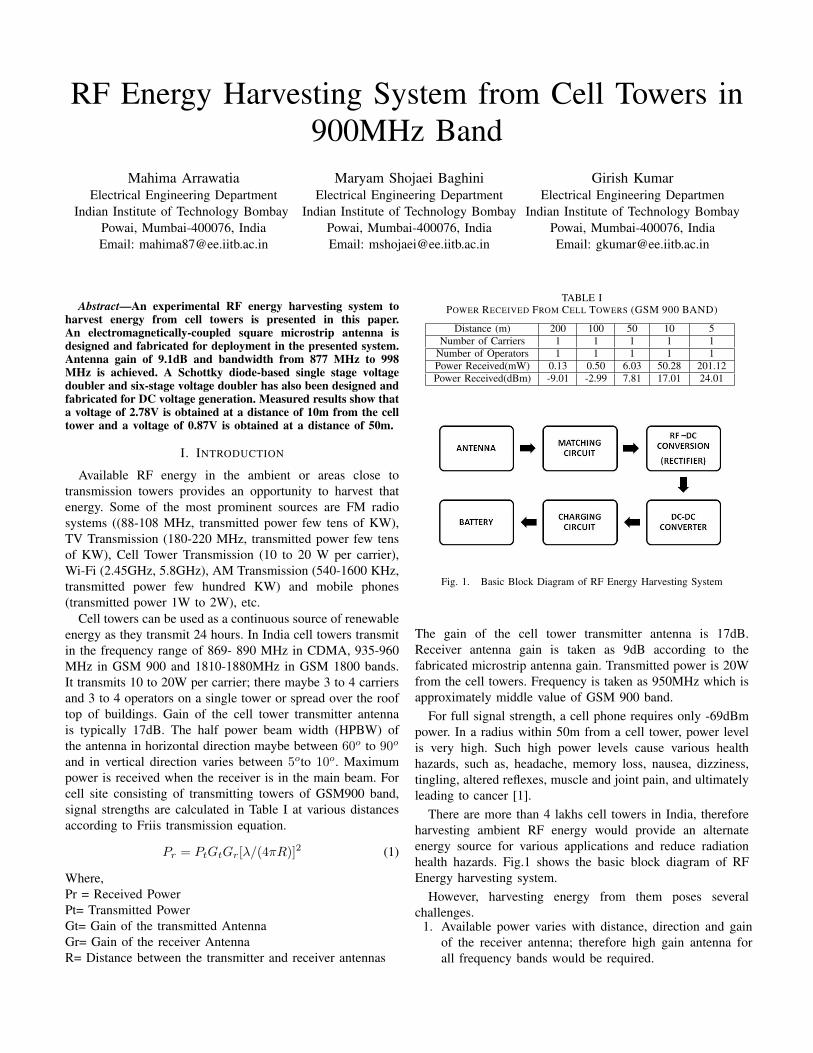
Simulated VSWR and input impedance plots of electro-magnetically coupled SMSA are shown Fig. 3(a) and (b).Bandwidth for VSWR less than 2 is from 877 to 998 MHzFig.4 shows the gain plot of the antenna. The gain of antennais 9.1 dB. Fig.5 shows measured VSWR plot and inputimpedance plot of SMSA. The antenna is designed for the935-960 MHz (GSM 900) band but it can also covers partof CDMA transmission band (869-890MHz).To enhance thegain, array of SMSA can be used.
III. RF TO DC CONVERSION USING SCHOTTKY DIODES
A voltage doubler is designed using Dickson Multipliertopology. Silicon based Schottky diode having threshold volt-age of 230 mV and diode capacitance of 0.26 pF is chosen.
(a) VSWR of Electromagnetically Coupled SMSA
(b) Input Impedance of Electromagnetically Coupled SMSA
Fig. 3. Simulated (a) VSWR and (b) Input impedance of ElectromagneticallyCoupled SMSA
At microwave frequency, the non-linear capacitance of thediode governs the maximum power transfer to the load andamplitude of the rectified output as input impedance of therectifier changes with frequency. Fig. 6 (a) and (b) shows asingle stage voltage doubler and 6 stage voltage doubler.
Both single stage and 6 stage voltage doubler circuits arefabricated. Fig.7 (a) and (b) show fabricated single stagevoltage doubler and 6-stage voltage doubler circuits respec-tively. Six-stage voltage doubler is implemented to measurethe power dependence of the rectifier for lower power level asthe voltage measured at single stage is very low. Single stagevoltage douber is used for rectenna measurements inside thelab and near the cell towers as the power level are higher atthese places.
Input impedance of the diode changes with the input power
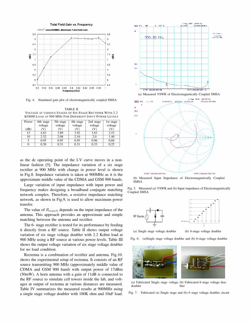
Fig. 4. Simulated gain plot of electromagnetically coupled SMSA
TABLE IIVOLTAGE AT VARIOUS STAGES OF SIX STAGE RECTIFIER WITH 2.2KOHM LOAD AT 900 MHZ FOR DIFFERENT INPUT POWER LEVELS
Power 6th stage 5th stage 4th stage 2nd stage 1st stagevoltage voltage voltage voltage voltage
(dB) (V) (V) (V) (V) (V)15 4.83 3.89 3.92 3.63 2.5310 2.32 2.08 2.10 2.0 1.405 0.95 0.95 0.95 0.96 0.680 0.30 0.31 0.31 0.33 0.25
as the dc operating point of the I-V curve moves in a non-linear fashion [5]. The impedance variation of a six stagerectifier at 900 MHz with change in power level is shownin Fig.8. Impedance variation is taken at 900MHz as it is theapproximate middle value of the CDMA and GSM 900 bands.
Large variation of input impedance with input power andfrequency makes designing a broadband conjugate matchingnetwork complex. Therefore, a resistive impedance matchingnetwork, as shown in Fig.9, is used to allow maximum powertransfer.
The value of Rmatch depends on the input impedance of theantenna. This approach provides an approximate and simplematching between the antenna and rectifier.
The 6- stage rectifier is tested for its performance by feedingit directly from a RF source. Table II shows output voltagevariation of six stage voltage doubler with 2.2 Kohm load at900 MHz using a RF source at various power levels. Table IIIshows the output voltage variation of six stage voltage doublerfor no load condition.
Rectenna is a combination of rectifier and antenna. Fig.10.shows the experimental setup of rectenna. It consists of an RFsource transmitting 900 MHz (approximately middle value ofCDMA and GSM 900 band) with output power of 17dBm(50mW). A horn antenna with a gain of 11dB is connected tothe RF source to simulate cell towers inside the lab, and volt-ages at output of rectenna at various distances are measured.Table IV summarizes the measured results at 900MHz usinga single stage voltage doubler with 100K ohm and 10uF load.
(a) Measured VSWR of Electromagnetically Coupled SMSA
(b) Measured Input Impedance of Electromagnetically CoupledSMSA
Fig. 5. Measured (a) VSWR and (b) Input impedance of ElectromagneticallyCoupled SMSA
(a) Single stage voltage doubler (b) 6-stage voltage doubler
Fig. 6. (a)Single stage voltage doubler and (b) 6-stage voltage doubler
(a) Fabricated Single stage voltagedoubler
(b) Fabricated 6-stage voltage dou-bler
Fig. 7. Fabricated (a) Single stage and (b) 6 stage voltage doubler circuit

(a) Input impedance and VSWR plot of six stage rectifier for an inputpower of -10dBm
(b) Input impedance and VSWR plot of six stage rectifier for aninput power of 10dBm
Fig. 8. Input impedance and VSWR plot of six stage rectifier for an inputpower of (a) -10dBm (b) 10dBm
Fig. 9. Approach used for resistive impedance matching
IV. MEASUREMENT AT ACTUAL SITE
Voltage levels are measured at actual site consisting oftransmission cell towers at Indian Institute of TechnologyBombay (IIT-B) using the fabricated electromagnetically cou-pled microstrip antenna and single stage voltage doubler.Figs.11 and 12 show the experimental setup for rectennameasurement at 50 m and 10 m from cell towers respectively.
The voltage obtained at 50 m was 0.87V.This voltage canbe stepped up using a boost converter. A stand alone boostconverter from Texas Instrument TPS61220 has been designedto work from an input voltage of 0.7V. Voltage at 50m after
TABLE IIIVOLTAGES AT 4TH - 6TH STAGES OF SIX STAGE VOLTAGE DOUBLER FOR
LOW INPUT POWER LEVELS FOR NO LOAD AT 900 MHz
Power 6th stage 5th stage 4th stage(dB) voltage (V) voltage (V) voltage (V)
-1 1.34 0.88 0.65-2 1.10 0.72 0.54-5 0.60 0.39 0.32
-10 0.21 0.14 0.16
TABLE IVRESULTS OF RECTENNA WITH SINGLE STAGE VOLTAGE DOUBLER AT
900MHz WITH 17dBm TRANSMITTED POWER
Distance Voltage(V) Voltage(V)(dB) no load 100K load60 3.45 3.3880 2.31 2.27
100 1.67 1.52120 1.48 1.34140 1.14 1.02160 0.83 0.68180 0.58 0.46
Fig. 10. Experimental setup for Rectenna measurement at 900MHz
Fig. 11. Experimental setup for Rectenna measurement at 50m from celltower (IIT-B)
stepping up can be used to charge a battery using a chargingcircuit.
At a distance of 10m voltage of 2.78V is obtained. Thislarge voltage can be used to charge a battery using a chargingcircuit.
The power level observed using a hand-held radiation mon-itor was 4dBm and 5dBm at 50m and 10m respectively.
Lower power levels are observed as the rectenna is not inthe main beam of the cell towers antenna.
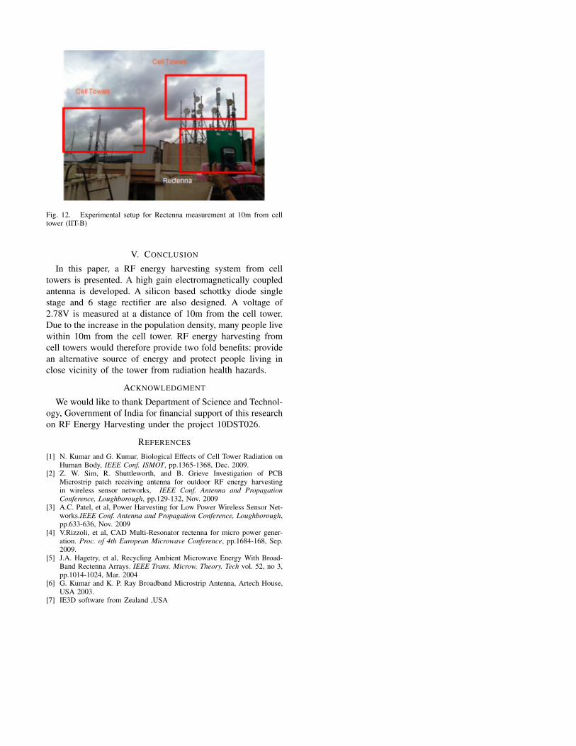
Fig. 12. Experimental setup for Rectenna measurement at 10m from celltower (IIT-B)
V. CONCLUSION
In this paper, a RF energy harvesting system from celltowers is presented. A high gain electromagnetically coupledantenna is developed. A silicon based schottky diode singlestage and 6 stage rectifier are also designed. A voltage of2.78V is measured at a distance of 10m from the cell tower.Due to the increase in the population density, many people livewithin 10m from the cell tower. RF energy harvesting fromcell towers would therefore provide two fold benefits: providean alternative source of energy and protect people living inclose vicinity of the tower from radiation health hazards.
ACKNOWLEDGMENT
We would like to thank Department of Science and Technol-ogy, Government of India for financial support of this researchon RF Energy Harvesting under the project 10DST026.
REFERENCES
[1] N. Kumar and G. Kumar, Biological Effects of Cell Tower Radiation onHuman Body, IEEE Conf. ISMOT, pp.1365-1368, Dec. 2009.
[2] Z. W. Sim, R. Shuttleworth, and B. Grieve Investigation of PCBMicrostrip patch receiving antenna for outdoor RF energy harvestingin wireless sensor networks, IEEE Conf. Antenna and PropagationConference, Loughborough, pp.129-132, Nov. 2009
[3] A.C. Patel, et al, Power Harvesting for Low Power Wireless Sensor Net-works.IEEE Conf. Antenna and Propagation Conference, Loughborough,pp.633-636, Nov. 2009
[4] V.Rizzoli, et al, CAD Multi-Resonator rectenna for micro power gener-ation. Proc. of 4th European Microwave Conference, pp.1684-168, Sep.2009.
[5] J.A. Hagetry, et al, Recycling Ambient Microwave Energy With Broad-Band Rectenna Arrays. IEEE Trans. Microw. Theory. Tech vol. 52, no 3,pp.1014-1024, Mar. 2004
[6] G. Kumar and K. P. Ray Broadband Microstrip Antenna, Artech House,USA 2003.
[7] IE3D software from Zealand ,USA