Embed Size (px)
Citation preview

RF Energy Harvesting and Battery-
Free Wireless Sensors
Pierre Mars, VP Applications Engineering, CAP-XX
Charlie Greene, Head of Technology Platforms, Powercast
Darnell nanoPower Forum, May 2009

Overview
• About CAP-XX
• About Powercast
• Application – Wireless Sensors
• System Overview
• System Performance
• Next Steps
• Summary
2

About CAP-XX
• World leader in thin, flat, small supercapacitors suitable for portable electronic devices
• Research-based, market-driven electronic components manufacturer. Founded in Australia in 1997. Listed on AIM in London, April 2006
• Turn-key power design solutions
• Production in Sydney & Malaysia
• Significant sales to big brand customers in Europe, Asia and North America
• CAP-XX supercapacitor technology licensed to Murata in 2008
• Distributors throughout USA, Europe and Asia
3
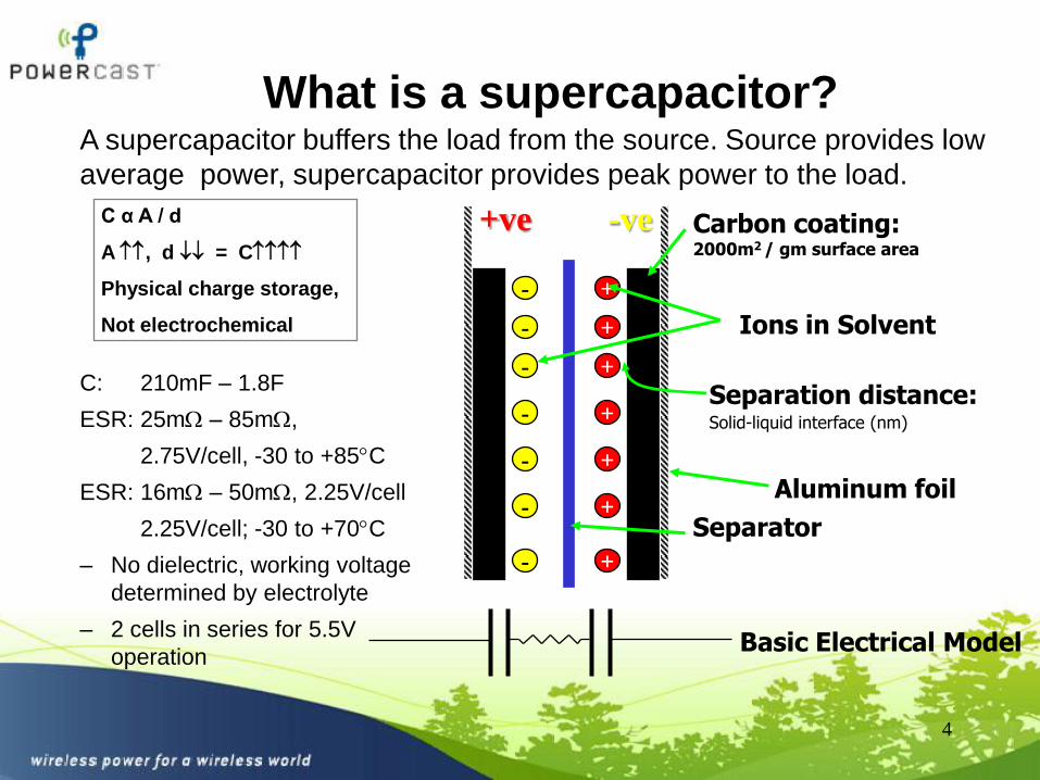
What is a supercapacitor?
4
Aluminum foil
Carbon coating:2000m2 / gm surface area
Separator
-
-
-
-
-
-
-
+
+
+
+
+
+
+
+ve -ve
Separation distance:Solid-liquid interface (nm)
C α A / d
A , d = C
Physical charge storage,
Not electrochemical Ions in Solvent
Basic Electrical Model
A supercapacitor buffers the load from the source. Source provides low
average power, supercapacitor provides peak power to the load.
C: 210mF – 1.8F
ESR: 25m – 85m,
2.75V/cell, -30 to +85C
ESR: 16m – 50m, 2.25V/cell
2.25V/cell; -30 to +70C
– No dielectric, working voltage
determined by electrolyte
– 2 cells in series for 5.5V
operation

About Powercast
• Driving innovation in the transmission, reception, and conversion of RF Energy
– Wireless Power Systems
– Renewable Power
• Applications
– Wireless sensors, RTLS, Long-range RFID
– Device recharging
– Lighting
– Defense
• Privately held, Founded 2003
5
Powerharvester™
Module
2009 Product
Showcase

Wireless Power
• Dedicated source transmits common radio waves– Ambient sources also available: Mobile/cellular, TV, Radio, etc.
• Proprietary receiver– captures the RF energy with an antenna
– efficiently converts the RF energy to the appropriate DC voltage
• Energy transfer is controllable and predictable by design
6

Wireless Sensors
• Building automation
• Energy management
• Process monitoring
• Condition monitoring
• Location tracking
• Reduced wiring
• Sealed devices
• Reduced maintenance
• Controllable power
• Difficult locations
7
Applications Benefits of Wireless Power

Issues with Primary Batteries
in Wireless Sensor Networks
• Intentional constraints to save power
– design, operation, application
• Reliability
• Temperature performance
• Battery replacement cost
• Limitations of scale
• Majority of energy is consumed in sleep mode
10s 100s 1000s
Man
ag
em
en
t E
ffo
rt
Size of Sensor Network
Battery-Free
Battery-Powered
Battery
Replacement
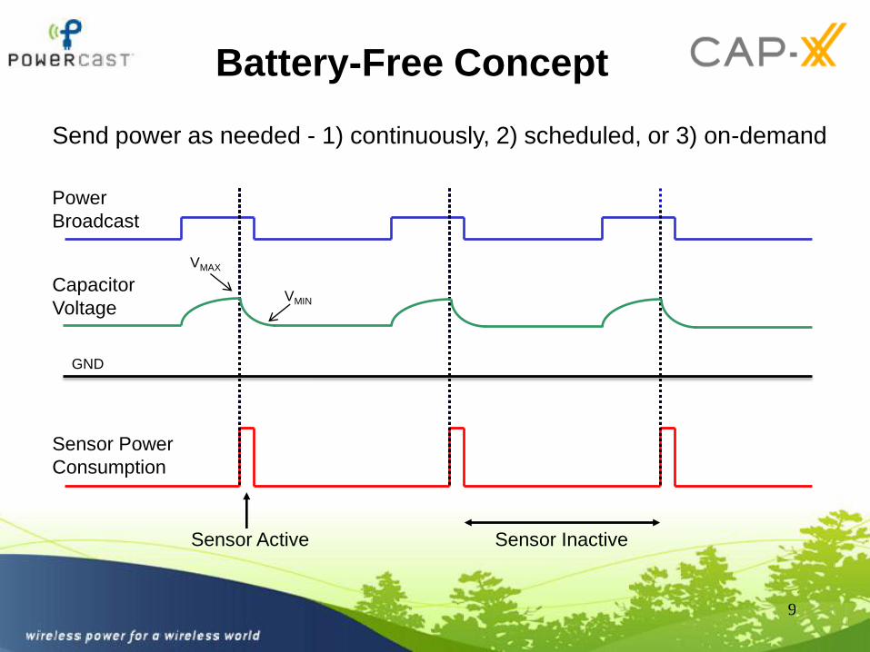
Sensor Inactive
Capacitor
Voltage
Power
Broadcast
Sensor Power
Consumption
Sensor Active
Battery-Free Concept
Send power as needed - 1) continuously, 2) scheduled, or 3) on-demand
9
VMIN
VMAX
GND
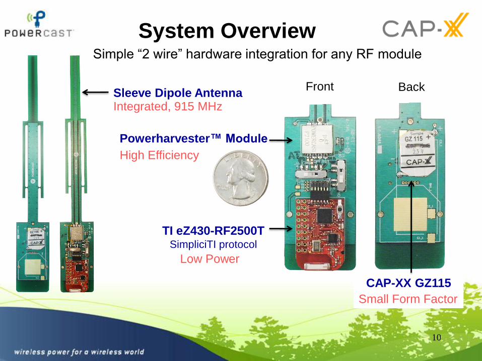
System Overview
10
Powerharvester™ Module
Front Back
TI eZ430-RF2500TSimpliciTI protocol
CAP-XX GZ115
Sleeve Dipole Antenna
Simple “2 wire” hardware integration for any RF module
High Efficiency
Low Power
Small Form Factor
Integrated, 915 MHz
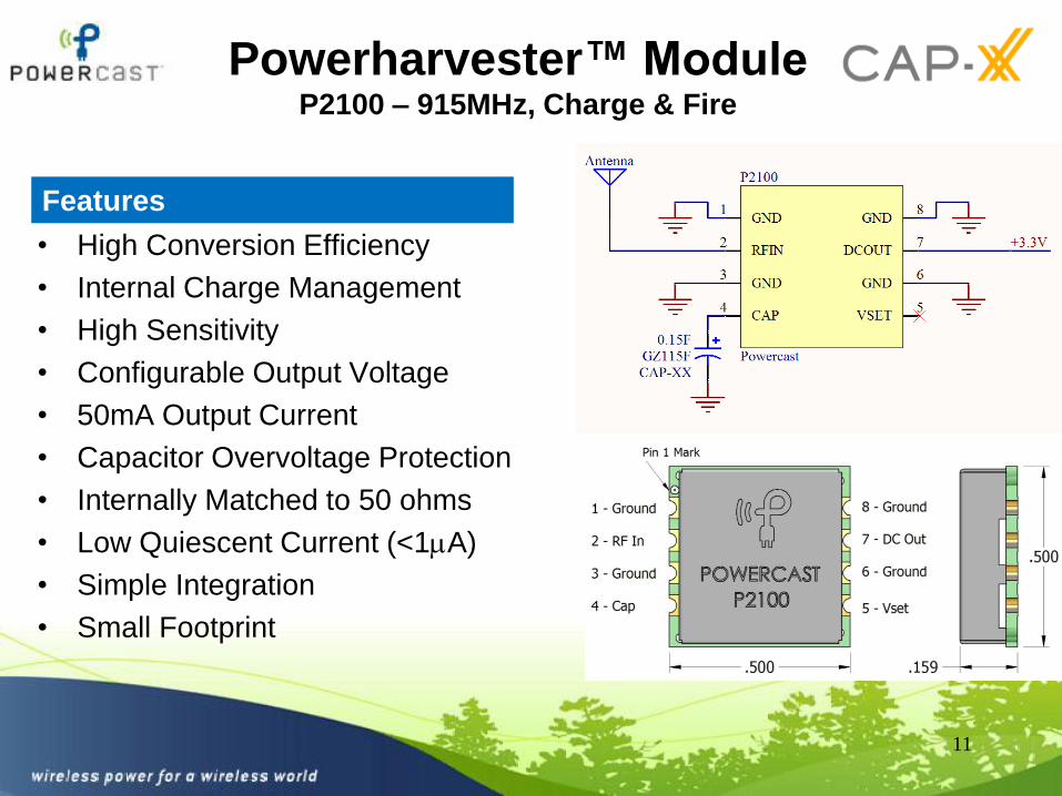
Powerharvester™ ModuleP2100 – 915MHz, Charge & Fire
• High Conversion Efficiency
• Internal Charge Management
• High Sensitivity
• Configurable Output Voltage
• 50mA Output Current
• Capacitor Overvoltage Protection
• Internally Matched to 50 ohms
• Low Quiescent Current (<1A)
• Simple Integration
• Small Footprint
11
Features
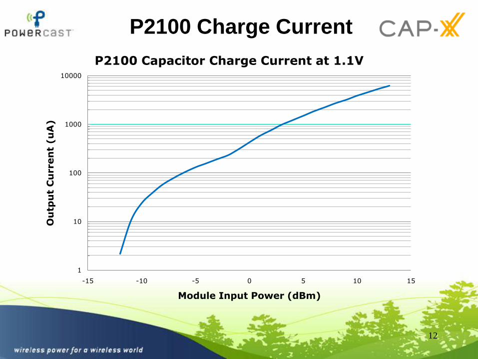
P2100 Charge Current
12
1
10
100
1000
10000
-15 -10 -5 0 5 10 15
Ou
tpu
t C
urren
t (u
A)
Module Input Power (dBm)
P2100 Capacitor Charge Current at 1.1V

Advantages of Low
Supercapacitor Voltage
• The P2100 charges the superapacitor to only ~1.2V
• Supercapacitor cell voltage is limited by the voltage stability of the electrolyte, there is no dielectric. Cell voltage of supercapacitors with organic electrolytes < 2.3V to 2.7V depending on the electrolyte.
• A low supply voltage allows the use of a single cell supercapacitor. This avoids the need for balancing between cells
– No balancing circuitry
– No current drawn by balancing circuit
• Reduced rate of supercapacitor ageing at lower voltage
• Reduced leakage current at lower voltage
13
GZ115 Leakage Current @ 23 deg C, 2.3V
0
2
4
6
8
10
12
14
16
18
20
0 10 20 30 40 50 60 70 80 90 100
Time (Hours)
Le
ak
ag
e C
urr
en
t (m
icro
Am
ps
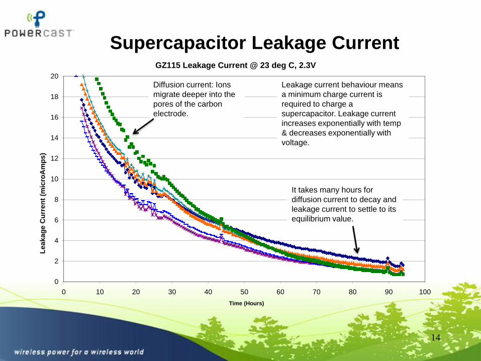
)Supercapacitor Leakage Current
14
Diffusion current: Ions
migrate deeper into the
pores of the carbon
electrode.
It takes many hours for
diffusion current to decay and
leakage current to settle to its
equilibrium value.
Leakage current behaviour means
a minimum charge current is
required to charge a
supercapacitor. Leakage current
increases exponentially with temp
& decreases exponentially with
voltage.
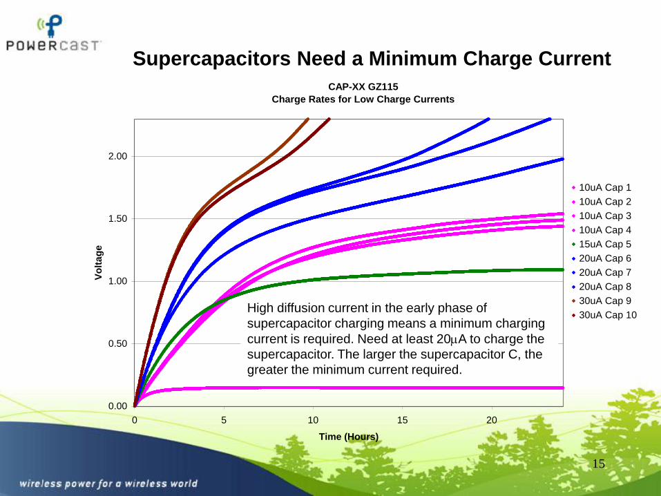
CAP-XX GZ115
Charge Rates for Low Charge Currents
0.00
0.50
1.00
1.50
2.00
0 5 10 15 20
Time (Hours)
Vo
lta
ge
10uA Cap 1
10uA Cap 2
10uA Cap 3
10uA Cap 4
15uA Cap 5
20uA Cap 6
20uA Cap 7
20uA Cap 8
30uA Cap 9
30uA Cap 10
Supercapacitors Need a Minimum Charge Current
15
High diffusion current in the early phase of
supercapacitor charging means a minimum charging
current is required. Need at least 20A to charge the
supercapacitor. The larger the supercapacitor C, the
greater the minimum current required.
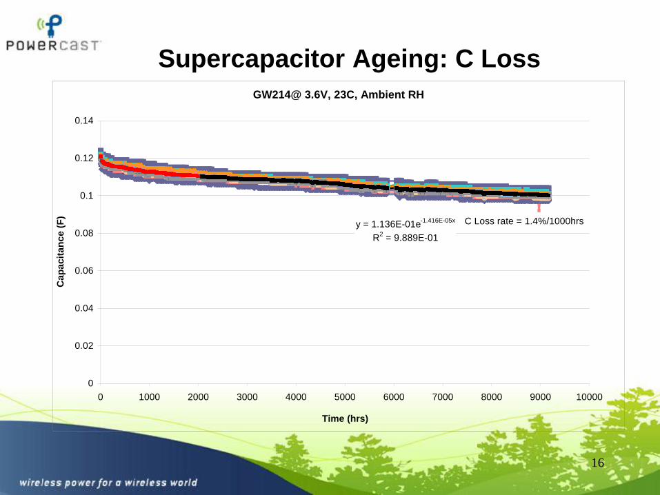
Supercapacitor Ageing: C Loss
16
GW214@ 3.6V, 23C, Ambient RH
y = 1.136E-01e-1.416E-05x
R2 = 9.889E-01
0
0.02
0.04
0.06
0.08
0.1
0.12
0.14
0 1000 2000 3000 4000 5000 6000 7000 8000 9000 10000
Time (hrs)
Ca
pa
cit
an
ce
(F
)
C Loss rate = 1.4%/1000hrs

GW214 ESR @ 3.6V, 23C, Ambient RH
y = 0.0027x + 71.706
R2 = 0.9168
0
20
40
60
80
100
120
140
160
180
200
0 1000 2000 3000 4000 5000 6000 7000 8000 9000 10000
Time (hrs)
ES
R (
mO
hm
s)
ESR rise rate of
2.7mOhms/1000hrs, or 3.4%
of initial ESR/1000hrs
Supercapacitor Ageing: ESR Rise
17
Supercapacitor Ageing
• Allow for ageing when sizing the supercapacitor
• Ageing depends on operating temperature and voltage
• GZ115 initial values 0.15F, 60m. At 1.2V, 23C:
– C loss after 10years 30% GZ115 C = 0.1F
– ESR increase after 10yrs 40% GZ115 ESR = 83m
• At 1.2V, 50C:
– C loss after 10years 70% GZ115 C = 0.047F
– ESR increase after 10yrs 40% GZ115 ESR = 230m
– This still operates the wireless transmitter. Supercapacitor will discharge from 1.16V to 1.04V.
• As a “rule of thumb”, double ESR and reduce C by 1/3 when sizing the supercapacitor.
18
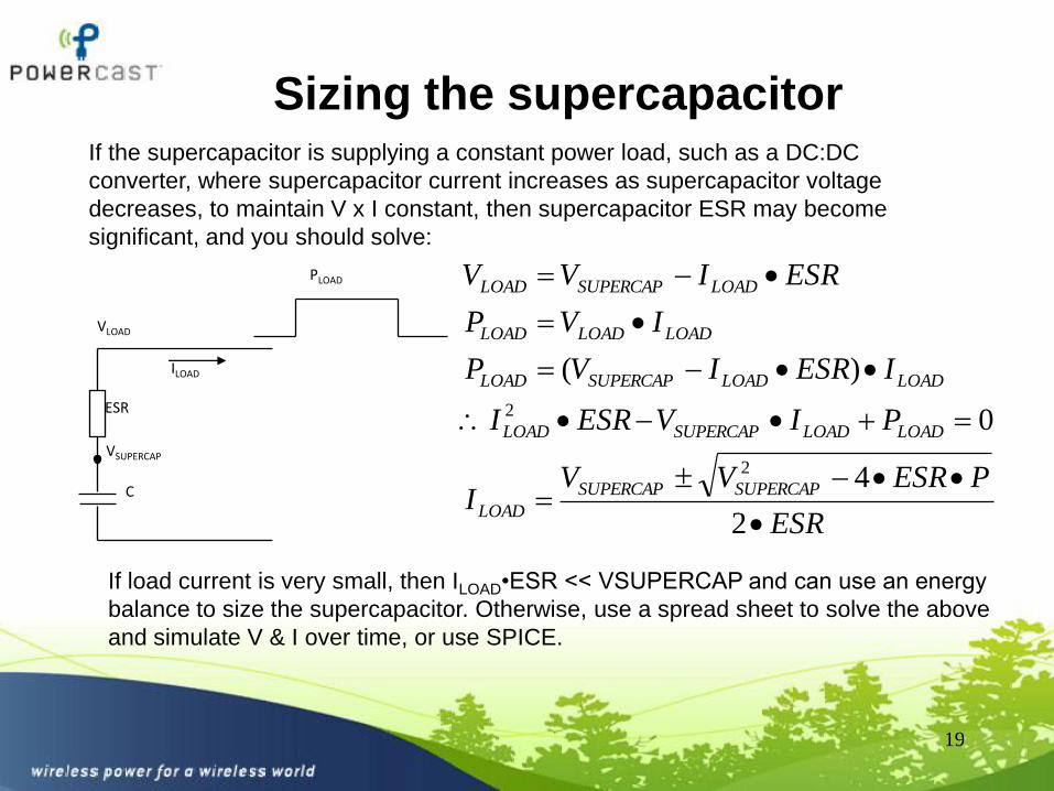
Sizing the supercapacitor
19
If the supercapacitor is supplying a constant power load, such as a DC:DC
converter, where supercapacitor current increases as supercapacitor voltage
decreases, to maintain V x I constant, then supercapacitor ESR may become
significant, and you should solve:
ESR
C
VSUPERCAP
VLOAD
ILOAD
PLOAD
ESR
PESRVVI
PIVESRI
IESRIVP
IVP
ESRIVV
SUPERCAPSUPERCAP
LOAD
LOADLOADSUPERCAPLOAD
LOADLOADSUPERCAPLOAD
LOADLOADLOAD
LOADSUPERCAPLOAD
2
4
0
)(
2
2
If load current is very small, then ILOAD•ESR << VSUPERCAP and can use an energy
balance to size the supercapacitor. Otherwise, use a spread sheet to solve the above
and simulate V & I over time, or use SPICE.
20
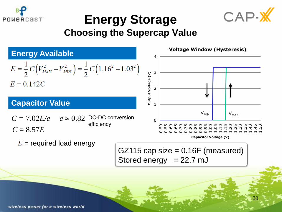
Energy StorageChoosing the Supercap Value
0
1
2
3
4
0.5
0
0.5
5
0.6
0
0.6
5
0.7
0
0.7
5
0.8
0
0.8
5
0.9
0
0.9
5
1.0
0
1.0
5
1.1
0
1.1
5
1.2
0
1.2
5
1.3
0
1.3
5
1.4
0
1.4
5
1.5
0
Ou
tpu
t V
olt
ag
e (
V)
Capacitor Voltage (V)
Voltage Window (Hysteresis)
DC-DC conversion
efficiency
Energy Available
Capacitor Value
= required load energyGZ115 cap size = 0.16F (measured)
Stored energy = 22.7 mJ
VMIN VMAX
C = 7.02E/e e 0.82
C = 8.57E
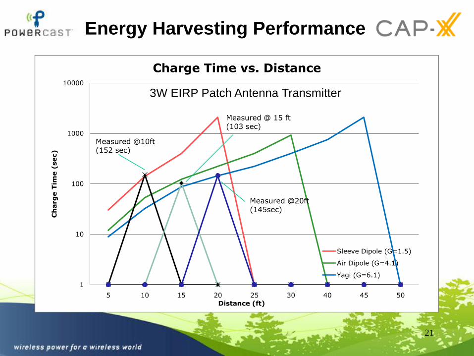
Energy Harvesting Performance
21
1
10
100
1000
10000
5 10 15 20 25 30 40 45 50
Ch
arg
e T
ime (
sec)
Charge Time vs. Distance
Sleeve Dipole (G=1.5)
Air Dipole (G=4.1)
Yagi (G=6.1)
Distance (ft)
Measured @10ft (152 sec)
Measured @ 15 ft(103 sec)
Measured @20ft (145sec)
3W EIRP Patch Antenna Transmitter
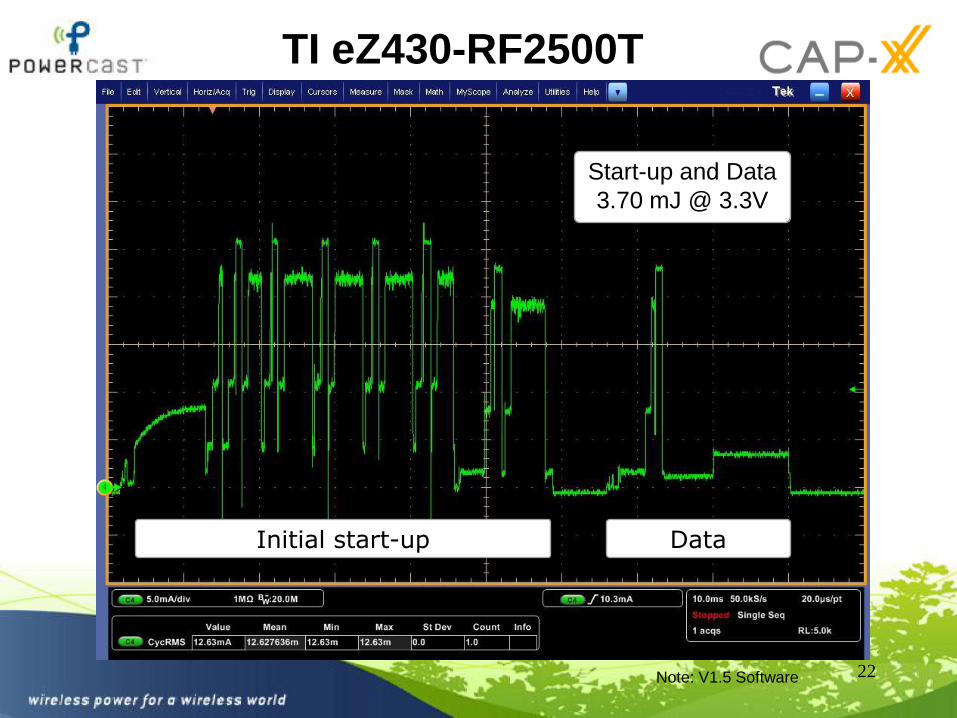
TI eZ430-RF2500T
22
Start-up and Data
3.70 mJ @ 3.3V
Note: V1.5 Software
Initial start-up Data
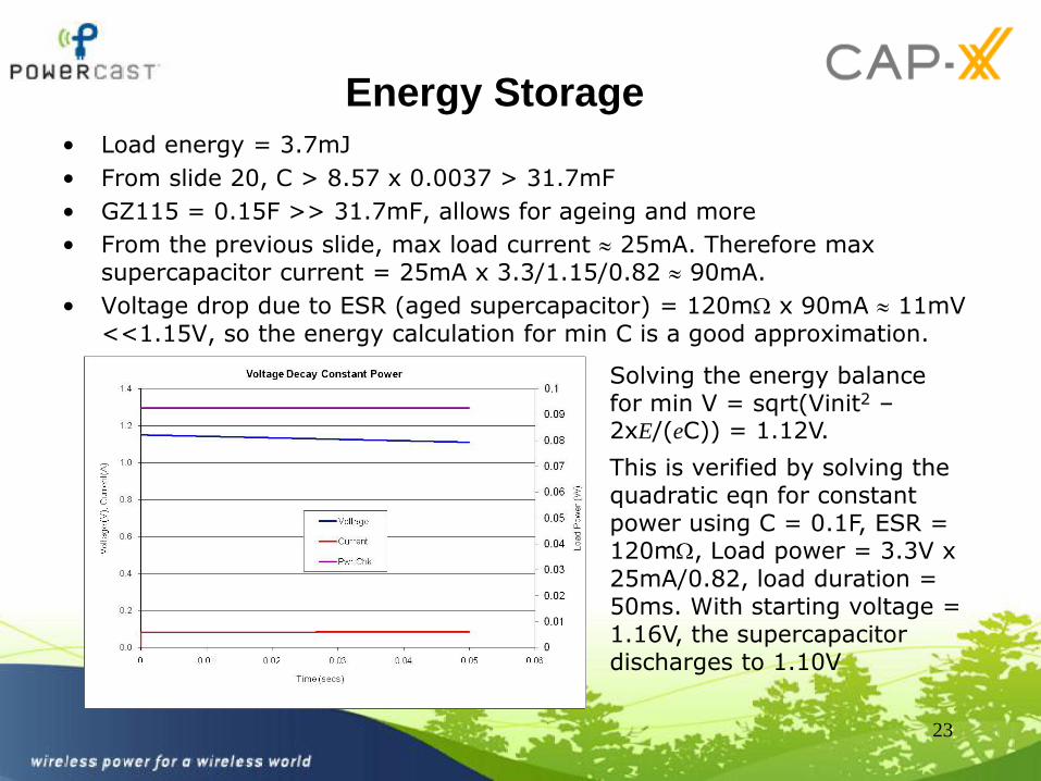
Energy Storage• Load energy = 3.7mJ
• From slide 20, C > 8.57 x 0.0037 > 31.7mF
• GZ115 = 0.15F >> 31.7mF, allows for ageing and more
• From the previous slide, max load current 25mA. Therefore max supercapacitor current = 25mA x 3.3/1.15/0.82 90mA.
• Voltage drop due to ESR (aged supercapacitor) = 120m x 90mA 11mV <<1.15V, so the energy calculation for min C is a good approximation.
23
Solving the energy balance for min V = sqrt(Vinit2 –2xE/(eC)) = 1.12V.
This is verified by solving the quadratic eqn for constant power using C = 0.1F, ESR = 120m, Load power = 3.3V x 25mA/0.82, load duration = 50ms. With starting voltage = 1.16V, the supercapacitordischarges to 1.10V
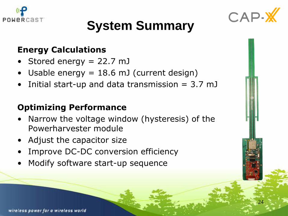
System Summary
Energy Calculations
• Stored energy = 22.7 mJ
• Usable energy = 18.6 mJ (current design)
• Initial start-up and data transmission = 3.7 mJ
Optimizing Performance
• Narrow the voltage window (hysteresis) of the Powerharvester module
• Adjust the capacitor size
• Improve DC-DC conversion efficiency
• Modify software start-up sequence
24
Next Steps
• Enable user configurable voltage hysteresis for additional flexibility
• Optimize software startup sequence to minimize the “energy overhead”
• Improve harvester input sensitivity to extend range
• Release system as a reference design
25

Summary
• Battery-free = maintenance-free
• Voltage window and cap sizing is important for operation cycle
• Low voltage charging increases life cycle performance of supercap
26

27
www.cap-xx.com
www.powercastco.com