Embed Size (px)
Citation preview
Page 1
1
Revisions to IEEE-519
Robert E. Fuhr, P.E.
2
What are Harmonics? A harmonic is a component frequency
of a harmonic motion of an electromagnetic wave that is an integral Multiply of the fundamental frequency. (Webster’s Dictionary)
Key words are – “Fundamental Frequency”– “Multiply”

Page 2
3
What are Harmonics? It is a mathematical way to break down
a non sinusoidal repeating waveforms (Fourier Analysis)
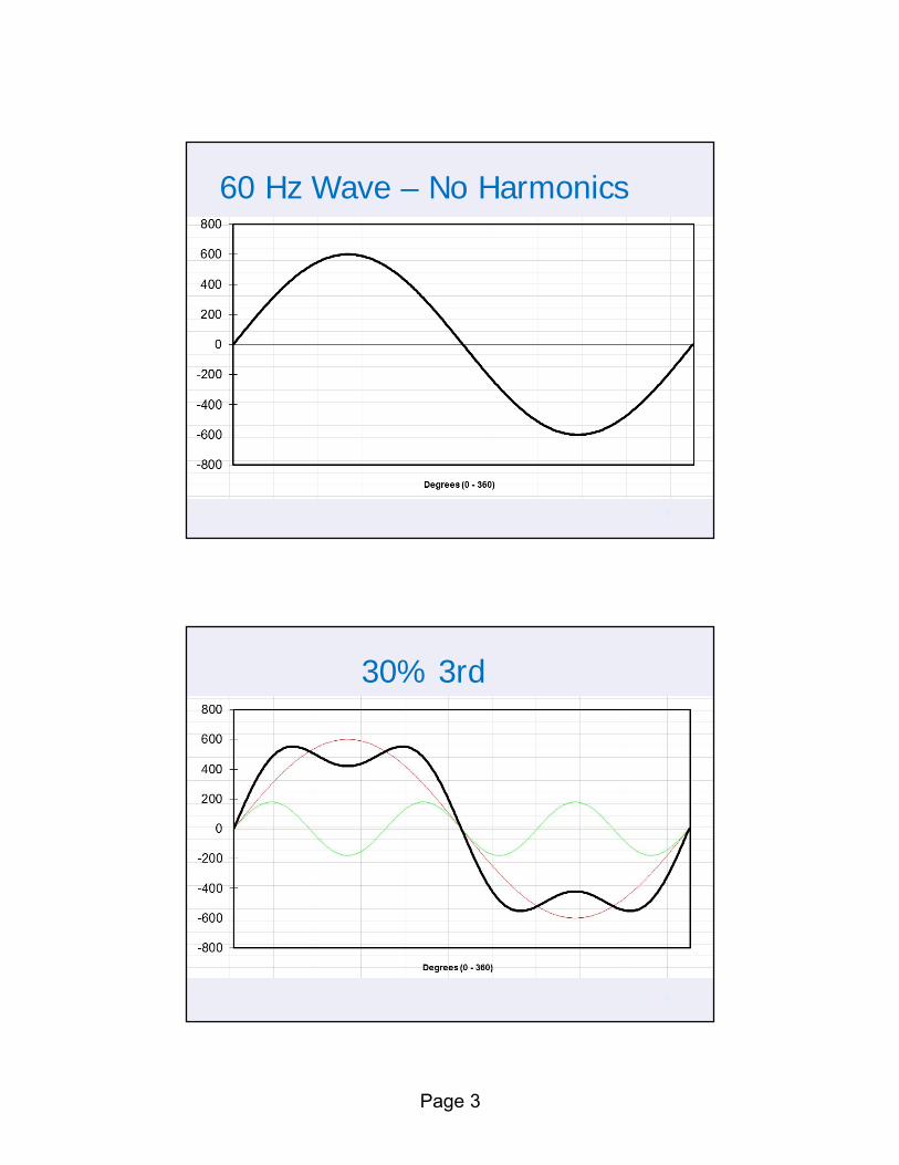
The total waveform is the sum of multiple sine waves that have different frequencies from the fundamental (60 Hz)
4
In the US, the fundamental frequency is 60 Hz
Integral Multiply means multiplying the fundamental frequency by a whole number(i.e. 2, 3, 4, …etc.)
3rd Harmonic is 3 X 60 Hz = 180 Hz
What are Harmonics?
Page 3
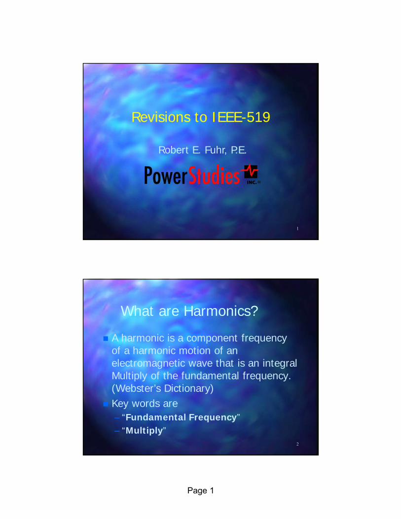
60 Hz Wave – No Harmonics
5
30% 3rd
6

Page 4
30% 3rd & 15% 5th
7
30% 3rd,15% 5th, & 5% 7th
8

Page 5
9
Sources of Harmonics Solid State Variable Speed Drives Arc Furnaces Rectifiers (AC-DC Converters) Solid State electronic devices which
contains a poor power supply– computers, TVs, laser printers, copy
machines… Solid State UPS units
10
Sources of Harmonics Welding Units Solid State Fluorescent & LED Lighting
Ballast Usually a problem for Industrial
Facilities– Heavy users of VSDs

Page 6
11
What Causes Harmonics?
Answer: Non-linear loads.
There are two types of loads: Linear and Non-linear.
12
Impedance Characteristics for Linear and Non-linear Devices
Volt-Amps graph for a linear device Volt-Amps graph for a non-linear device
A
V
A
V

Page 7
13
Linear Load
When a sine-wave voltage is connected to a load of linear elements, the current will always be a sine-wave of the same frequency.
14
Non-Linear Load
When the load contains a combination of linear and non-linear elements, the current can be distorted containing harmonics of higher frequencies.

Page 8
15
A Typical Non-Linear Load
The diode -capacitor input circuit draws short pulses of line current during the peak of the line voltage.
16
Electrical Equivalent Circuit
The load can be represented by a resistor in parallel with several current generators operating at harmonic frequencies.

Page 9
17
Effects of Harmonics Overheated Transformers Heating Of Motors Abnormal skin effect heating on
conductors. Heating Of Neutral Conductors Low Voltage At End Loads High Neutral To Ground Voltages At
End Loads
18
Effects of Harmonics Distorted Voltage Communication Problems Capacitor Bank Application Problems Unreliable Operation Of Electronic
Equipment Control Of Speed And Voltage Problems
On Emergency Generators Current Measurement Problems
Page 10
19
Effects of Harmonics Operation Problems Of Relays And
Circuit Breakers
20
IEEE – 519Recommended Practice
andRequirements for
Harmonic Control inElectric Power Systems

Page 11
21
It is a “Recommended Practice”, not a “Standard”.
It is a “system” practice, not an “equipment” practice.
Addresses the steady state condition. Only addresses harmonic limits at PCC,
not within the facility. Harmonic Current Limits For Utility
Customers`
IEEE – 519 – What is it?
22
IEEE-519 - Philosophy of the Standard
The customer is responsible for limiting the amount of harmonic current injected back into the overall power system.
The utility is responsible for avoiding resonance conditions on the power system – causes unacceptable distortion levels.

Page 12
23
IEEE-519 - Philosophy of the Standard
Basically, the utility promises a voltage quality.
IEEE – 519 - PCC Harmonic current limits are measured
at the point of common coupling (PCC) between the utility and the customer.
PCC: A point on a public power supply system where it connects to the customer.– Usually where the utility meter is
connected.24

Page 13
IEEE – 519 IL
Maximum Demand Load Current, IL: established at PCC and should be taken as the sum of the current corresponding to the maximum demand during each of the twelve previous months divided by 12.
IL = maximum demand load current at PCC under normal load operating conditions. 25
IEEE – 519 Isc ISC = maximum short-circuit current at
PCC.
26

Page 14
IEEE – 519 - THD% THD (total harmonic distortion): ratio of
the root mean square of the harmonic content, – Uses harmonic components up to the 50th
order – Excludes interharmonics– Expressed as a percent of the fundamental– Typical PQ meter measurement
27
IEEE – 519 - TDD% TDD (total demand distortion): ratio of
the root mean square of the harmonic content. – Uses harmonic components up to the 50th
order – Excludes interharmonics.– Expressed as a percent of maximum
demand current.– Most PQ Meters do not measure TDD%.
28
Page 15
IEEE – 519 – THD & TDD THD and TDD are not the same! TDD prevents a user from being
penalized for harmonics during periods of light loading.
Chapter 4 contains new info regarding harmonic measurements – instruments must comply with IEC 61000-4-7 and IEC 61000-4-30
29
30
At the PCC, system owners or operators (Utilities) should limit line-to-neutral voltage harmonics as follows:– Daily 99th percentile very short time (3 s)
values should be less than 1.5 times the values given in Table 1.
– Weekly 95th percentile short time (10 min) values should be less than the values given in Table 1.
IEEE-519 Voltage Distortion Limits

Page 16
31
IEEE-519 Voltage Distortion Limits
IEEE – 519 Current Limits Harmonic Current Limits For Utility
Customers Harmonic current limits are measured
at the point of common coupling (PCC) between the utility and the customer.
32

Page 17
33
IEEE-519 Current Distortion Limits - 120 V to 69 kV
34
IEEE-519 Current Distortion Limits - 69 kV to 161 kV

Page 18
35
IEEE-519 Current Distortion Limits - >161 kV
36
IEEE-519 Current Distortion Limits -
At the PCC, users should limit harmonic currents shown in the (3) Limit Tables.

Page 19
37
IEEE-519 - Current Distortion Limits
Daily 99th percentile very short time (3 s) harmonic currents should be less than 2.0 times the values given in Table 2.
Weekly 99th percentile short time (10 min) harmonic currents should be less than 1.5 times the values given in Table 2.
Weekly 95th percentile short time (10 min) harmonic currents should be less than the values given in Table 2.
38
IEEE-519 - Harmonics – How to Reduce Them
Filters– Passive (Tuned Filters)– Active (Fast Switching Harmonic Canceling)
Higher Pulse Drives (12, 18 vs 6 Pulse) Phase Shifting Transformers Specify higher quality power supplies
for computers, PLCs and other electronic equipment.
Page 20
39
Key Points to Remember!!! Non-linear loads create harmonics. Harmonics create abnormal skin effect
heating on conductors. Capacitors and harmonics (non-linear
loads) do not mix!!!! IEEE-519 Standard is to be applied at
the PCC, not downstream equipment (i.e. MCCs, Panelboards, VSDs)
40
Key Points to Remember!!! Incorrect to specify equipment that
must meet IEEE 519 Standard.

Page 21
41
For More Information… www.powerstudies.com Contact us! Bob Fuhr
Ph 253-639-8535Fax 253-639-868522443 SE 240th StMaple Valley, [email protected]