Embed Size (px)
Citation preview
E05122-K00084-00
Ver3-1.05
COPYRIGHT (C) 2014,2015,2016 HKS CO.,LTD. ALLRIGHT RESERVED.
Revision History
Revision Date Contents
Change the procedure of the Installation of the EVC6-IR 2.4 driver software(Ver3-1.04)2015/3/20
Add "Windows 10" to system requirements(Ver3-1.05)2016/1/20
Add the description of the Installation of the EVC6-IR 2.4 driver software(Ver3-1.03)2015/1/10
Add the description of the EVC6-IR 2.4(Ver3-1.02)2014/12/25
Create New(Ver3-1.01)2014/3/10
Thank you for purchasing the HKS EVC and EasyWriter for EVC6.
The EasyWriter for EVC6 is a data editing tool for the EVC.
The EVC data can be edited using this software.
Please read the following instructions carefully to understand the functions effectively and in a safe manner.
The symbols indicated below depict the warning levels.
There may be risk of severe injury or death.
There may be risk of injury.There may be risk of fire damage to the vehicle.
●Do not attempt to tune the vehicle on the street. � Always tune on a dynomometer.
●Be extremely careful not to input wrong values. � There is a risk of damaging the engine.� HKS will not be responsible for any damages. ●The driver should not attempt to use the EasyWriter for EVC6 while driving. � There may be risk of causing an accident.
●This manual indicates items you need to pay attention to in order to install this product safely and lists precautions to avoid any
possible damage and/or accidents.
●Please contact your dealer for purchasing consumable parts and lost or missing part.
●To use this product on the public road, follow the necessary procedures if there are any regulations for a tuned vehicle.
●HKS will not be responsible for any damage caused by incorrect use or use after modification and/or dismantling of this product.
●This product was designed for installation and use on a factory vehicle or a vehicle using other HKS products. The performance
and/or safety cannot be guaranteed if this product is installed onto other vehicles than mentioned above.
●This product is applicable for any vehicle that operates on a DC12V negative ground.
●The specifications of this product including installation are subject to change without prior notice.
●This manual is subject to revise without prior notice.
1
This software is intended only for those who have accepted the following terms and agreements. �Read the following agreement and proceed upon approval.
1.EasyWriter for EVC6 software requires a permit for usage
2.Copyright
3.Rights
4.Reproduction and modification
5.Disclaimer
・Pentium M 1GHz or greater processor (Multi-core CPU recommended)
・Windows XP Service Pack 3 (SP3), Vista, Windows 7, Windows 8, Windows 8.1, Windows 10
・.NET Framework 3.5-
・256MB or more RAM(512MB or more recommended)
・500MB or higher available hard disk space
・XGA(1,024×768) or higher resolution monitor(WXGA(1,280×800) or higher resolution recommended)
・Mouse or other pointing device
・USB connector
・Internet Accessible
※This program may not function in some computers even if it meets system requirements due to incompatibility reasons.
※Windows XP, Vista, Windows7, Windows 8, Windows 8.1 and Windows 10 Operating Systems, .NET Framework are products of Microsoft
Corporation.
Copyright is property of HKS Co., Ltd.
1)User is allowed to install on only one computer system per software purchased.
2)This software may not be transferred or lended to any third party other than what is indicated in 3).
3)Software may be transferred to another party only if the following requirements are met.
・All contents including but not limited to the Software Usage Agreement, instruction manual, and all software are transferred to the new user. ・The original user must delete all copies of the program on the original computer(s). ・The new user must agree to this contract. If the software is upgraded to a newer version, and any previous versions are saved, all older versions of the software must be transferred to the new user.
4)This agreement is effective from the date the EasyWriter for EVC6 is installed.
1) The EasyWriter for EVC6 disk and documents included are not to be reproduced (copied) or modified in any way.
2)The user and/or any third party may not edit, change, disperse, or disassemble the program or hardware. Failure to comply will void all warranty claims.
3)Reproduction of all or any part of this manual without written consent from HKS Co., Ltd. is prohibited unless stated by law.
HKS Co., Ltd. will not be held responsible for any damages caused to the vehicle(s) or to the computer(s) by use of this software. HKS Co., Ltd. cannot guarantee that this product will suit the users'needs, nor guarantee that the program will be error-free. HKS Co., Ltd. will not be held responsible for any damages inflicted directly or indirectly by use of this program. HKS Co., Ltd. will not be held responsible for any conflict or dispute that may arise between the user and a third party as a result of using this program.
2
Introduction�・・・・・・・・・・・・・・・・・・・・・・・・・・・・・� �1
Warnings for safety�・・・・・・・・・・・・・・・・・・・・・・・・・� �1
Software usage consent�・・・・・・・・・・・・・・・・・・・・・・・� �2
System Requirements�・・・・・・・・・・・・・・・・・・・・・・・・� �2
Contents�・・・・・・・・・・・・・・・・・・・・・・・・・・・・・・・� �3
1.Connecting the Communication Adaptor�・・・・・・・・・・・・・・� �4
2.Installation� ・・・・・・・・・・・・・・・・・・・・・・・・・・・・� �5
2- 1.Download of the EasyWriter for EVC6�・・・・・・・・・・・� �5
2-2.Installation of the USB driver�・・・・・・・・・・・・・・・� �6
Oparation
3.Icon�・・・・・・・・・・・・・・・・・・・・・・・・・・・・・・・・� �10
4.Setting Tabs�・・・・・・・・・・・・・・・・・・・・・・・・・・・・� �11
4- 1.[Basic Setting]Tab �・・・・・・・・・・・・・・・・・・・・� �11
4-2.[Map Set]Tab �・・・・・・・・・・・・・・・・・・・・・・� �12
4-3.[Vehicle Set]Tab �・・・・・・・・・・・・・・・・・・・・・� �17
4-4.[Initial Set-Up]Tab �・・・・・・・・・・・・・・・・・・・・� �18
4-5.[Function]Tab �・・・・・・・・・・・・・・・・・・・・・・� �19
4-6.[Scramble]Tab �・・・・・・・・・・・・・・・・・・・・・・� �20
4-7.[Data Lock]Tab �・・・・・・・・・・・・・・・・・・・・・� �21
4-8.[Comment]Tab �・・・・・・・・・・・・・・・・・・・・・・� �21
5.Data Monitor Function�・・・・・・・・・・・・・・・・・・・・・・・� �22
5- 1.Data Monitor� ・・・・・・・・・・・・・・・・・・・・・・・� �22
6.Data Log Function�・・・・・・・・・・・・・・・・・・・・・・・・・� �23
6- 1.Data Log� ・・・・・・・・・・・・・・・・・・・・・・・・・� �23
6-2.Log Link� ・・・・・・・・・・・・・・・・・・・・・・・・・� �24
6-3.Comparison Log�・・・・・・・・・・・・・・・・・・・・・・� �24
7.Option Funciton�・・・・・・・・・・・・・・・・・・・・・・・・・・� �25
7- 1.Display Comparison File/Paste from Comparison File�・・・� �25
8.Other�・・・・・・・・・・・・・・・・・・・・・・・・・・・・・・・� �26
8- 1.All Reset� ・・・・・・・・・・・・・・・・・・・・・・・・・� �26
8-2.COM Port�・・・・・・・・・・・・・・・・・・・・・・・・・� �26
8-3.Language�・・・・・・・・・・・・・・・・・・・・・・・・・� �26
8-4.About EasyWriter�・・・・・・・・・・・・・・・・・・・・・� �26
3
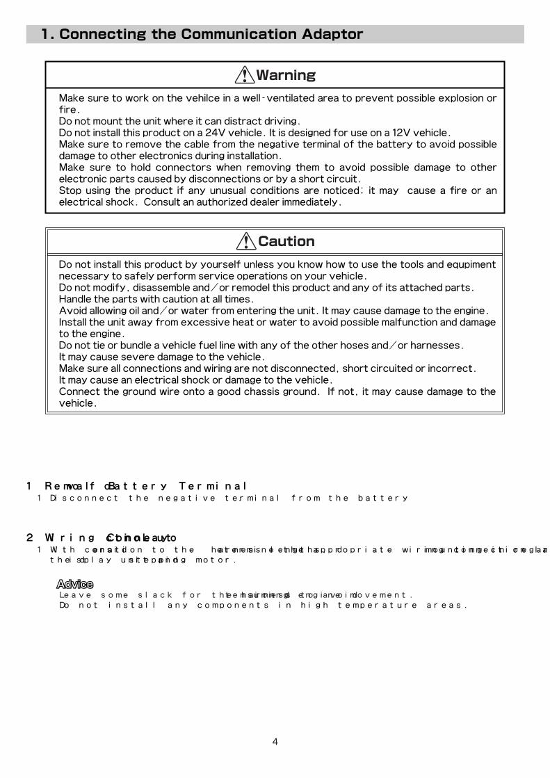
●Make sure to work on the vehilce in a well-ventilated area to prevent possible explosion or fire.
●Do not mount the unit where it can distract driving.●Do not install this product on a 24V vehicle. It is designed for use on a 12V vehicle.●Make sure to remove the cable from the negative terminal of the battery to avoid possible
damage to other electronics during installation.●Make sure to hold connectors when removing them to avoid possible damage to other
electronic parts caused by disconnections or by a short circuit.●Stop using the product if any unusual conditions are noticed; it may cause a fire or an
electrical shock. Consult an authorized dealer immediately.
1.Removal of Battery Terminal
2.Wiring Connection Layout
(1)�Disconnect the negative terminal from the battery.
(1)�With consideration to the harness lengths, determine the appropriate wiring connection layout and mounting in regards to � the display unit and stepping motor.
●Do not install this product by yourself unless you know how to use the tools and equpiment necessary to safely perform service operations on your vehicle.
●Do not modify, disassemble and/or remodel this product and any of its attached parts.●Handle the parts with caution at all times.●Avoid allowing oil and/or water from entering the unit. It may cause damage to the engine.●Install the unit away from excessive heat or water to avoid possible malfunction and damage
to the engine.●Do not tie or bundle a vehicle fuel line with any of the other hoses and/or harnesses. ●It may cause severe damage to the vehicle.●Make sure all connections and wiring are not disconnected, short circuited or incorrect. ●It may cause an electrical shock or damage to the vehicle.●Connect the ground wire onto a good chassis ground. If not, it may cause damage to the
vehicle.
・Leave some slack for the harness to avoid tension during engine movement.・Do not install any components in high temperature areas.
4
EngineCompartment
Vehicle Interior
EVC Stepping Motor
3 PIN Connector
Main Harness
Extension Harness
4 PIN ConnectorDisplay Unit
Display Unit
Power Harness
Speed / RPM Signal Harness(White)
Connection Adaptor
Connection Cable (USB cable)To PC
Throttle Signal Harness (Blue)
2 PIN Connector
CONNECT
5 PIN Connector
(3)�Reinstall all removed factory parts.
(4)�Reconnect the negative battery cable to the battery terminal.
2-1.Download of the EasyWriter for EVC6
(1)�Download the EasyWriter for EVC6 from HKS’ website.
(2)�Unzip the downloaded file. “EasyWriter_6.exe” in the � folder is the software of EasyWriter for EVC6.
The following is the procedure to install the EasyWriter for EVC6 software.
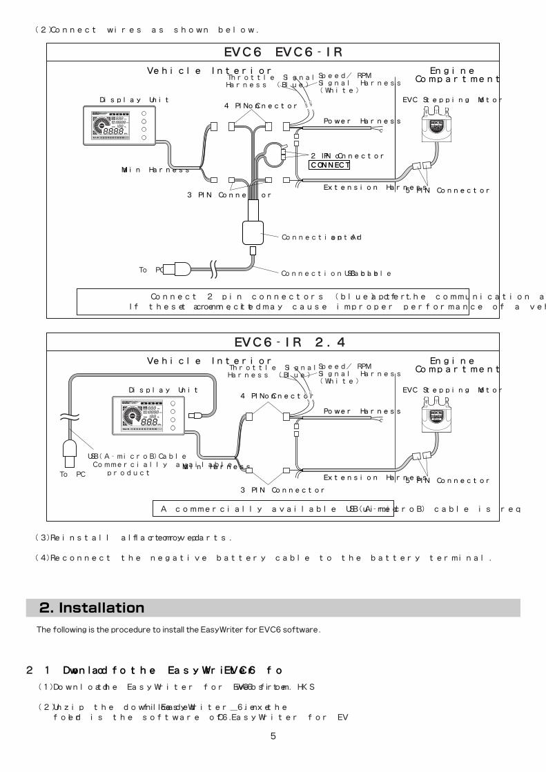
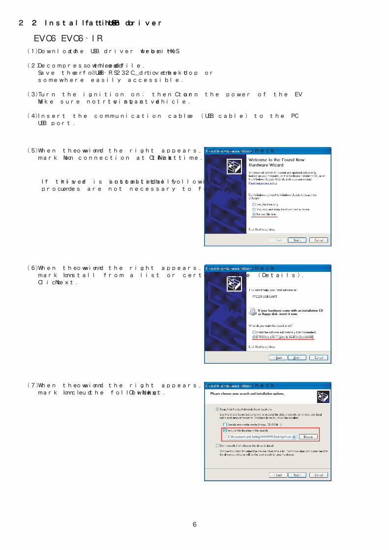
(2)�Connect wires as shown below.
3 PIN Connector
4 PIN Connector
EngineCompartment
Vehicle Interior
EVC Stepping Motor
Main Harness
Extension Harness
Power Harness
Speed / RPM Signal Harness(White)
USB(A-microB)Cable (Commercially available product)To PC
Throttle Signal Harness (Blue)
5 PIN Connector
EVC6、EVC6-IR
EVC6-IR 2.4
Connect 2 pin connectors (blue) of the communication adapter.If these aren’t connected, it may cause improper performance of a vehicle.
A commercially available USB(A-microB) cable is required.
5
2-2.Installation of the USB driver
(1)�Download the USB driver from HKS’ website.
(2)�Decompress the downloaded file. � Save the folder (USB-RS232C_driver)to the desktop or � somewhere easily accessible.
(3)�Turn the ignition on; then turn the power of the EVC on. � Make sure not to start driving a vehicle.
(4)�Insert the communication cable (USB cable) to the PC’s � USB port.
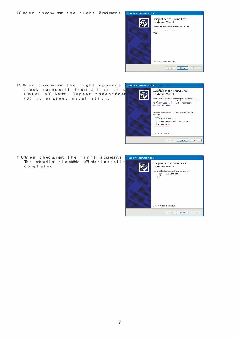
(5)�When the window on the right appears, place a check � mark on “No connection at this time.” Click “Next.”
(6)�When the window on the right appears, place a check � mark on “Install from a list or certain place (Details).” � Click “Next.”
(7)�When the window on the right appears, place a check � mark on “Include the following:” Click “Next.”
●If this driver is installed automatically, the following procedures are not necessary to follow.
6
◆EVC6、EVC6-IR
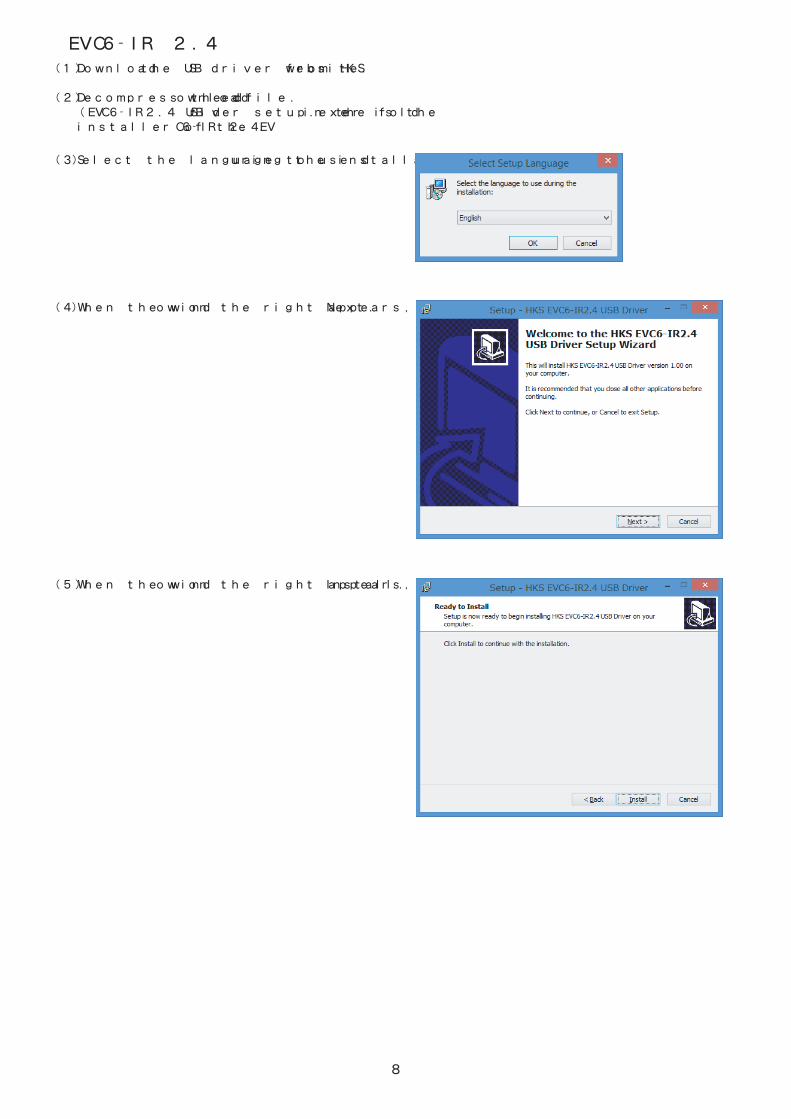
(8)�When the window on the right appears, click “Finish.”
(9)�When the window on the right appears again, place a � check mark on “Install from a list or certain place � (Details).” Click “Next.” Repeat the procedure (6) to � (8) to proceed with installation.
(10)�When the window on the right appears, click “Finish.” � The window is closed, and the USB driver’s installation is � completed.
7
8
◆EVC6-IR 2.4
(1)�Download the USB driver from HKS’ website.
(2)�Decompress the downloaded file. � (EVC6-IR2.4 USB driver setup.exe) in the folder is the � installer of the EVC6-IR 2.4.
(3)�Select the language to use during the installation.
(4)�When the window on the right appears, click “Next.”
(5)�When the window on the right appears, click “Install.”

9
(6)�When the window on the right appears, click “Finish.” � The window is closed, and the USB driver’s installation is � completed.
10
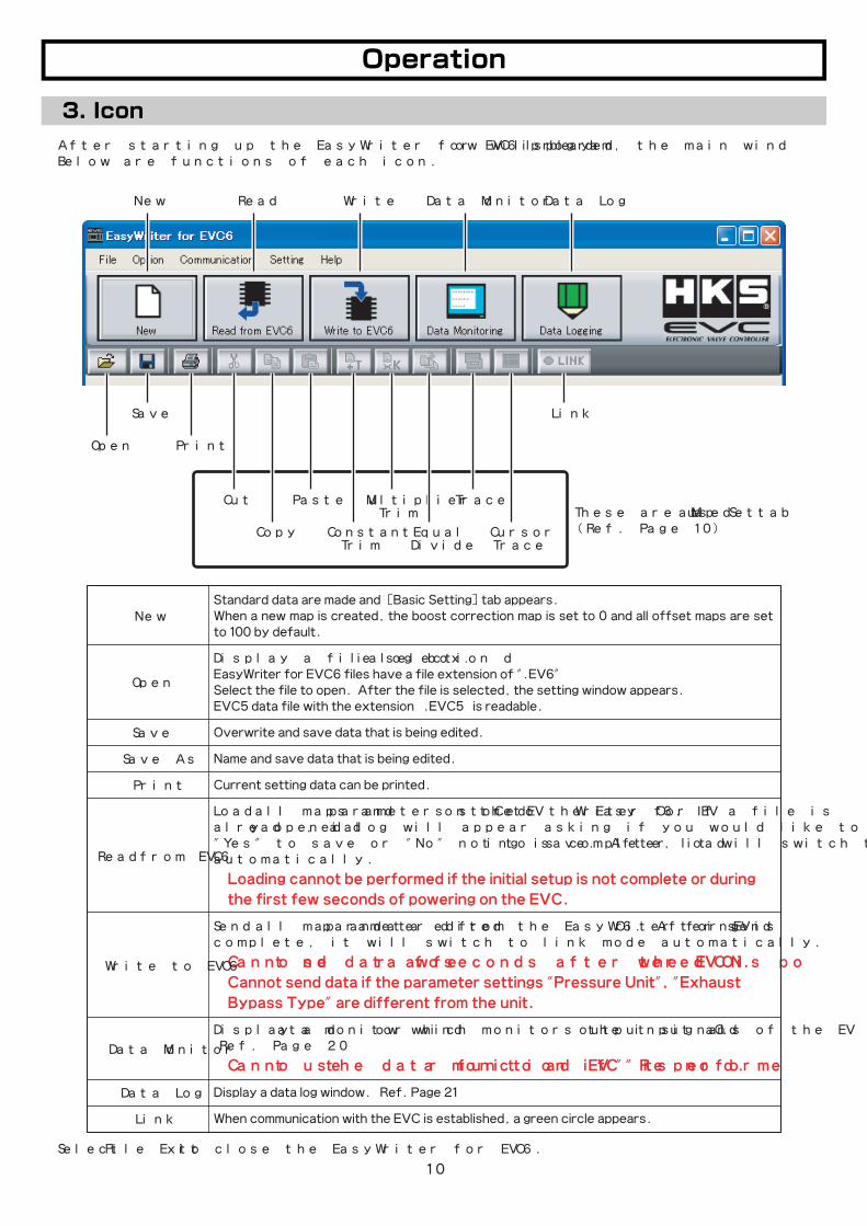
After starting up the EasyWriter for EVC6 program, the main window will be displayed. Below are functions of each icon.
Standard data are made and [Basic Setting]tab appears.When a new map is created, the boost correction map is set to 0 and�all offset maps are set to 100 by default.
Display a file selection dialog box. EasyWriter for EVC6 files have a file extension of ".EV6"Select the file to open. After the file is selected, the setting window appears.EVC5 data file with the extension “.EVC5” is readable.
Overwrite and save data that is being edited.
Name and save data that is being edited.
Current setting data can be printed.
Load all maps and parameters stored on the EVC to the EasyWriter for EVC6. If a file is already opened, a dialog will appear asking if you would like to save before closing. Select "Yes" to save or "No" not to save. After loading is complete, it will switch to link mode automatically.
※Loading cannot be performed if the initial setup is not complete or during
the first few seconds of powering on the EVC.
Send all map and parameter data edited from the EasyWriter for EVC6. After sending is complete, it will switch to link mode automatically.
※Cannot send data for a few seconds after the EVC is powered ON.
※Cannot send data if the parameter settings "Pressure Unit", "Exhaust
Bypass Type" are different from the unit.
Display a data monitor window which monitors the input and output signals of the EVC. (Ref. Page 20)
※Cannot use the data monitor function if "Read EVC" is not performed.
Display a data log window. (Ref. Page 21)
When communication with the EVC is established, a green circle appears.
Select 「File→Exit」 to close the EasyWriter for EVC6.
New
Open
Save
Save As
Data Log
Link
Data Monitor
Write to EVC6
New
ConstantTrim
Read
Open
MultiplierTrim
Write
Save
EqualDivide
Link
Data Log
Data Monitor
Cut Trace
CursorTrace
Copy
PasteThese are used at [Map Set] tab(Ref. Page 10)
Read from EVC6
・After setting the initial setup, start up the data monitor to make sure the RPM, speed, and throttle are displayed correctly.
11
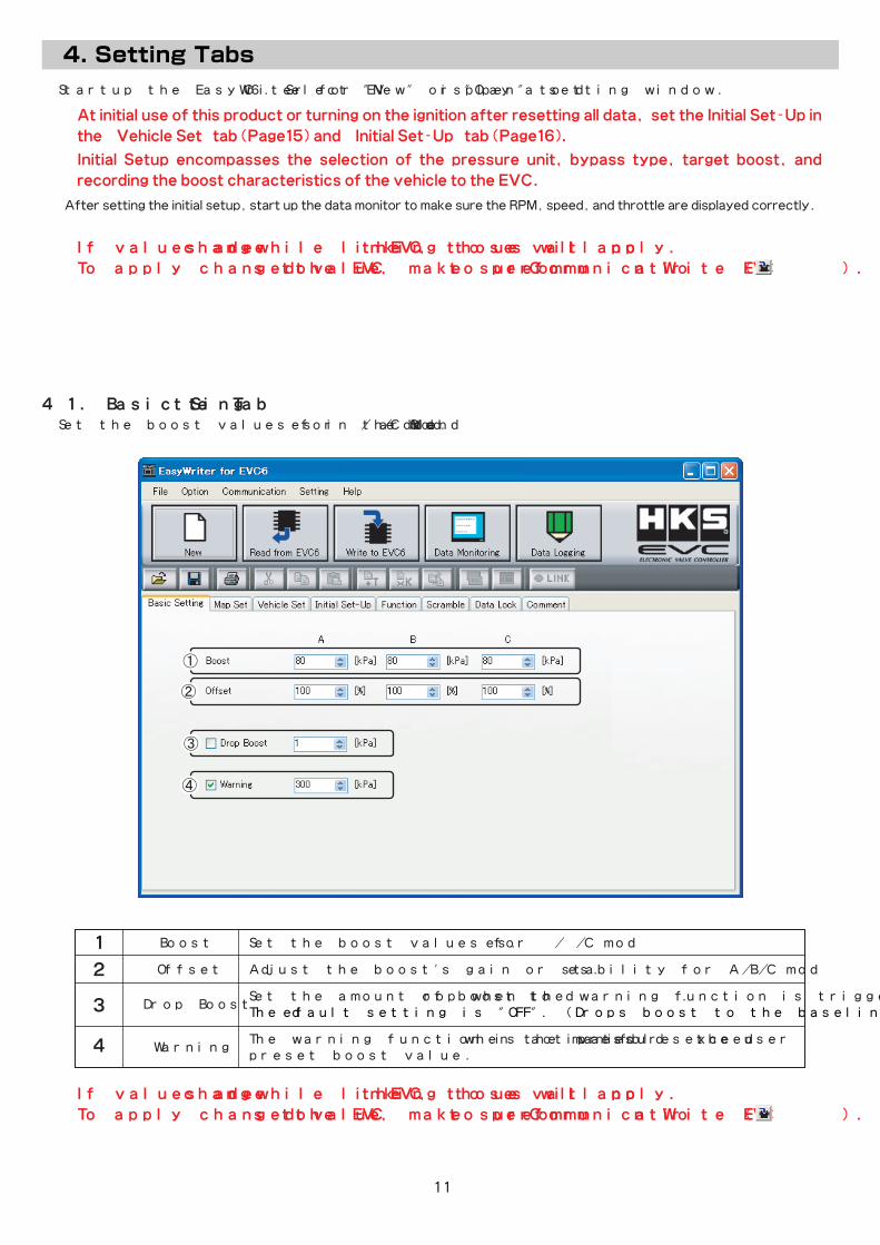
Startup the EasyWriter for EVC6. Select "New" or "Open" to display a setting window.
※At initial use of this product or turning on the ignition after resetting all data, set the Initial Set-Up in
the [Vehicle Set] tab(Page15) and [Initial Set-Up] tab(Page16).
●Initial Setup encompasses the selection of the pressure unit, bypass type, target boost, and
recording the boost characteristics of the vehicle to the EVC.
4-1.� [Basic Setting] TabSet the boost values for A/B/C modes in the Standard Mode.
� Boost� Set the boost values for A/B/C modes.
� Offset� Adjust the boost's gain or stability for A/B/C modes.
� .� Set the amount of boost to drop when the warning function is triggered. �
Drop Boost� The default setting is "OFF". (Drops boost to the baseline boost value)
�Warning
� The warning function is activated when the manifold pressure exceeds the user � .� preset boost value.
※If values are changed while linking to the EVC, those values will not apply.
To apply changed values to the EVC, make sure to perform 「Communication→Write EVC」( ).
※If values are changed while linking to the EVC, those values will not apply.
To apply changed values to the EVC, make sure to perform 「Communication→Write EVC」( ).
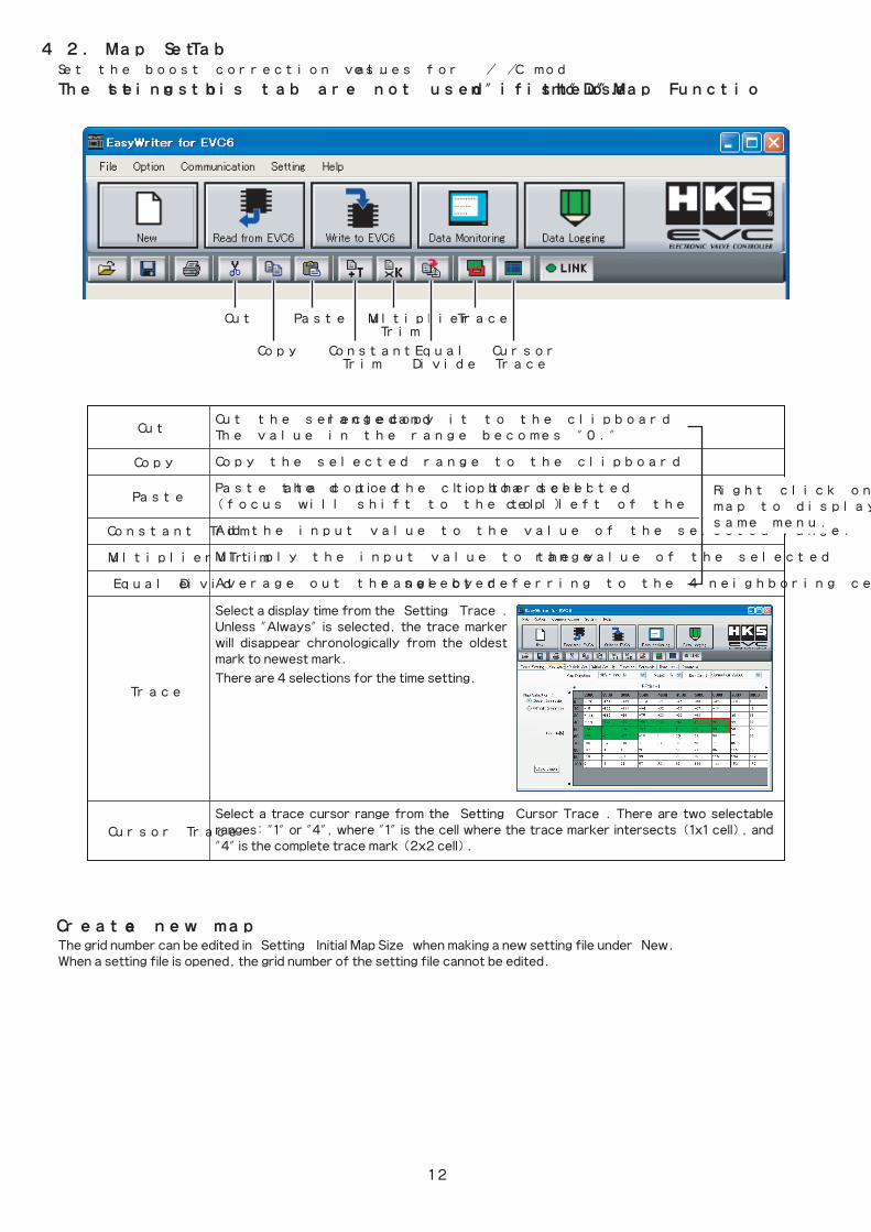
Cut the selected range and copy it to the clipboard.The value in the range becomes "0."
Copy the selected range to the clipboard.
Paste the data copied to the clipboard to the selected cell.(focus will shift to the top left of the selected cell)
Add the input value to the value of the selected range.
Multiply the input value to the value of the selected range.
Average out the selected range by referring to the 4 neighboring cell values.
Select a display time from the 「Setting→Trace」. Unless "Always" is selected, the trace marker will disappear chronologically from the oldest mark to newest mark.
There are 4 selections for the time setting.
Select a trace cursor range from the 「Setting→Cursor Trace」. There are two selectable ranges: "1" or "4", where "1" is the cell where the trace marker intersects (1x1 cell), and "4" is the complete trace mark (2x2 cell).
12
4-2.� [Map Set] TabSet the boost correction values for A/B/C modes.
Right click on the map to display the same menu.
�Constant Trim
�Multiplier Trim
�Equal Divide
Trace
Cursor Trace
Cut
�Copy
�Paste
The settings on this tab are not used if the "Map Function" is "Do not use".
ConstantTrim
MultiplierTrim
EqualDivide
Cut Trace
CursorTrace
Copy
Paste
The grid number can be edited in 「Setting→Initial Map Size」 when making a new setting file under “New.”When a setting file is opened, the grid number of the setting file cannot be edited.
◆Create a new map
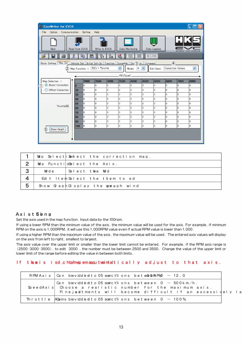
Set the axis used in the map function. Input data by the 100rpm.
If using a lower RPM than the minimum value of the axis, the minimum value will be used for the axis. For example, if minimum RPM on the axis is 1,000RPM, it will use this 1,000RPM value even if actual RPM value is lower than 1,000.
If using a higher RPM than the maximum value of the axis, the maximum value will be used. The entered axis values will display on the axis from left to right, smallest to largest.
The axis value over the upper limit or smaller than the lower limit cannot be entered. For example, if the RPM axis range is (2500-3000-3500), to edit “3000”, the number must be between 2500 and 3500. Change the value of the upper limit or lower limit of the range before editing the value in between both limits.
13
If the axis is changed, the map will automatically adjust to that axis.
◆Axis Setting
� RPM Axis� Can be divided into 5 or 10 sections between 0 ̃ 12,000RPM.
� � Can be divided into 5 or 10 sections between 0 ̃ 500km/h. � Speed Axis� ※Choose a realistic number for the maximum axis.� � Fine adjustments will become difficult if an excessively large value is entered.
� Throttle Axis� Can be divided into 5 or 10 sections between 0 ̃ 100%.
� Map Selection� Select the correction map.
� Map Function� Select the Axis.
� Mode� Select the Mode.
� Edit Item� Select the item to edit.
� Show Graph� Display the graph window.
14
◆Boost Correction Map
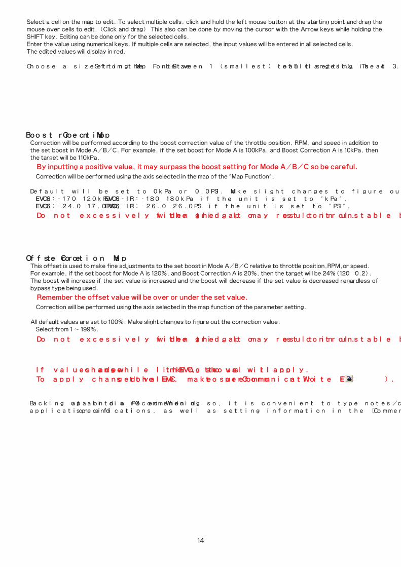
Select a cell on the map to edit. To select multiple cells, click and hold the left mouse button at the starting point and drag the mouse over cells to edit. (Click and drag) This also can be done by moving the cursor with the Arrow keys while holding the SHIFT key. Editing can be done only for the selected cells. Enter the value using numerical keys. If multiple cells are selected, the input values will be entered in all selected cells.The edited values will display in red.
Choose a size from the 「Setting→Map FontSize」 between 1 (smallest) to 5 (largest). The default setting is at 3.
◆Offset Correction Map
※If values are changed while linking to the EVC, those values will not apply.
To apply changed values to the EVC, make sure to perform 「Communication→Write EVC」( ).
※Do not excessively widen the gap of the grid. It may result in unstable boost control.
※Do not excessively widen the gap of the grid. It may result in unstable boost control.
Correction will be performed according to the boost correction value of the throttle position, RPM, and speed in addition to the set boost in Mode A/B/C. For example, if the set boost for Mode A is 100kPa, and Boost Correction A is 10kPa, then the target will be 110kPa.
※By inputting a positive value, it may surpass the boost setting for Mode A/B/C so be careful.
※Correction will be performed using the axis selected in the map of the "Map Function".
Default will be set to 0kPa or 0.0PSI. Make slight changes to figure out the correction value. EVC6:-170~120kPa,� EVC6-IR:-180~180kPa if the unit is set to "kPa". EVC6:-24.0~17.0PSI,�EVC6-IR:-26.0~26.0PSI if the unit is set to "PSI".
This offset is used to make fine adjustments to the set boost in Mode A/B/C relative to throttle position,RPM,or speed.For example, if the set boost for Mode A is 120%, and Boost Correction A is 20%, then the target will be 24%(120×0.2). The boost will increase if the set value is increased and the boost will decrease if the set value is decreased regardless of bypass type being used.
※Remember the offset value will be over or under the set value.
※Correction will be performed using the axis selected in the map function of the parameter setting.
All default values are set to 100%. Make slight changes to figure out the correction value. Select from 1 ̃ 199%.
Backing up all data onto a PC is recommended. When doing so, it is convenient to type notes/comments about the vehicle application and specifications, as well as setting information in the [Comment] tab.
15
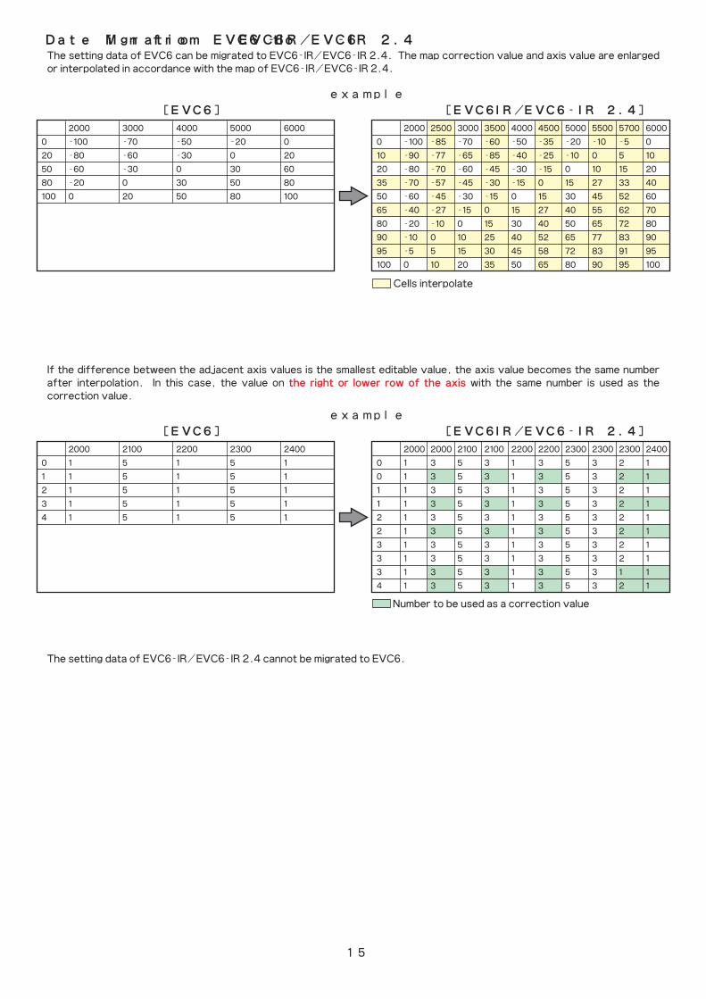
The setting data of EVC6 can be migrated to EVC6-IR/EVC6-IR 2.4. The map correction value and axis value are enlarged or interpolated in accordance with the map of EVC6-IR/EVC6-IR 2.4.
Cells interpolate
If the difference between the adjacent axis values is the smallest editable value, the axis value becomes the same number after interpolation. In this case, the value on the right or lower row of the axis with the same number is used as the correction value.
◆Date Migration from EVC6 to EVC6-IR/EVC6-IR 2.4
� 2000� 3000� 4000� 5000� 6000
0� -100� -70� -50� -20� 0
20� -80� -60� -30� 0� 20
50� -60� -30� 0� 30� 60
80� -20� 0� 30� 50� 80
100� 0� 20� 50� 80� 100
� 2000�2500�3000�3500�4000�4500�5000�5500�5700�6000
0� -100�-85� -70� -60� -50� -35� -20� -10� -5� 0
10� -90� -77� -65� -85� -40� -25� -10� 0� 5� 10
20� -80� -70� -60� -45� -30� -15� 0� 10� 15� 20
35� -70� -57� -45� -30� -15� 0� 15� 27� 33� 40
50� -60� -45� -30� -15� 0� 15� 30� 45� 52� 60
65� -40� -27� -15� 0� 15� 27� 40� 55� 62� 70
80� -20� -10� 0� 15� 30� 40� 50� 65� 72� 80
90� -10� 0� 10� 25� 40� 52� 65� 77� 83� 90
95� -5� 5� 15� 30� 45� 58� 72� 83� 91� 95
100� 0� 10� 20� 35� 50� 65� 80� 90� 95� 100
� 2000� 2100� 2200� 2300� 2400
0� 1� 5� 1� 5� 1
1� 1� 5� 1� 5� 1
2� 1� 5� 1� 5� 1
3� 1� 5� 1� 5� 1
4� 1� 5� 1� 5� 1
� 2000�2000�2100�2100�2200�2200�2300�2300�2300�2400
0� 1� 3� 5� 3� 1� 3� 5� 3� 2� 1
0� 1� 3� 5� 3� 1� 3� 5� 3� 2� 1
1� 1� 3� 5� 3� 1� 3� 5� 3� 2� 1
1� 1� 3� 5� 3� 1� 3� 5� 3� 2� 1
2� 1� 3� 5� 3� 1� 3� 5� 3� 2� 1
2� 1� 3� 5� 3� 1� 3� 5� 3� 2� 1
3� 1� 3� 5� 3� 1� 3� 5� 3� 2� 1
3� 1� 3� 5� 3� 1� 3� 5� 3� 2� 1
3� 1� 3� 5� 3� 1� 3� 5� 3� 1� 1
4� 1� 3� 5� 3� 1� 3� 5� 3� 2� 1
<example>
[EVC6] [EVC6-IR/EVC6-IR 2.4]
<example>
[EVC6] [EVC6-IR/EVC6-IR 2.4]
Number to be used as a correction value
The setting data of EVC6-IR/EVC6-IR 2.4 cannot be migrated to EVC6.
Axis List
Edit CellView
AdjustmentButton
16
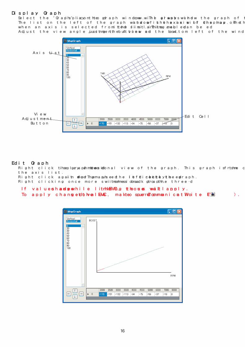
※If values are changed while linking to the EVC, those values will not apply.
To apply changed values to the EVC, make sure to perform 「Communication→Write EVC」( ).
Display Graph� Select the "Graph" icon to display the graph window. The graph window will always show the graph of the map. � The list on the left of the graph window is the axis of the map. The data of the axis will display on the bottom cell of the graph � when an axis is selected from the list. This cell can be edited similar to map editing. � Adjust the view angle using the 4 view adjustment buttons on the bottom left of the window.
Edit Graph� Right click the graph to display a two-dimensional view of the graph. This graph is the cross section of the axis selected from � the axis list. � Right click again for graph edit mode. Then use the left click to edit directly onto the graph. � Right clicking once more switches back to the three-dimensional graph.
17
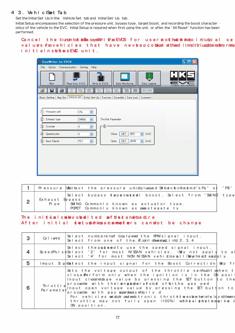
Set the Initial Set-Up in the [Vehicle Set] tab and [Initial Set-Up] tab.
Initial Setup encompasses the selection of the pressure unit, bypass type, target boost, and recording the boost character-istics of the vehicle to the EVC. Initial Setup is required when first using the unit, or after the "All Reset" function has been performed.
4-3.�[Vehicle Set] Tab
※Cancel the initial setup on the EasyWriter for EVC6 for users that do not know the initial setup
values or for vehicles that have never completed initial setup. Use the instruction manual to perform
initial setup on the EVC unit.
※The initial setup can only be edited after new data is created.
After initial setup is complete, these parameters cannot be changed.
�Cylinder
� Select number of cylinders to use the RPM signal input.� � � Select from one of the following: 1,2,3,4,6,or 8 cylinders.
� � Select the speed pulse to use the speed signal input.� Speed Pulse� Select "2" for most NISSAN vehicles. (May not apply to all NISSAN vehicles) � � Select "4" for most NON-NISSAN vehicles. (May not apply to all vehicles)
� Imput Signal� Select the input signal for the Boost Correction Map from "Revolution(RPM)" or "Speed".
� � Sets the voltage output of the throttle sensor when the throttle is fully open and fully � � closed. Perform only when the ignition is in the ON position and the engine is stopped. � � � Input closed voltage value by pressing the SET button to the right of CLOSE. Perform this �
Throttle � procedure with the engine at idle and your foot off the gas pedal.
�Parameter
� Input open voltage value by pressing the SET button to the right of OPEN. Perform this � � procedure with gas pedal fully depressed.� � ※For vehicles equipped with electronic throttle control systems (drive-by-wire), the � � throttle may not fully open (100%) while the engine is stopped and the ignition is in the � � ON position.
� Pressure Unit� Select the pressure unit used for boost display. Select from "kPa" or "PSI"
� � Select bypass type used to control boost. Select from "SWING" type or "POPPET" type.� Exhaust Bypass�� Pipe� SWING�:Commonly known as actuator type.� � POPET�:Commonly known as wastegate type.

18
Set the Initial Set-Up in the [Vehicle Set] tab and [Initial Set-Up] tab.
Initial Setup encompasses the selection of the pressure unit, bypass type, target boost, and recording the boost character-istics of the vehicle to the EVC. Initial Setup is required when first using the unit, or after the "All Reset" function has been performed.
4-4.� [Initial Set-Up] Tab
If known, set the maximum boost value, after installing the EVC.
When the standard maximum boost value is larger than the initial boost value or the boost mode A/B/C, the same value of the standard maximum boost is entered to the initial boost value or the boost mode A/B/C.
The initial value when creating new data is 60kPa or 8.7PSI.※For vehicles equipped with a variable solenoid valve, the maximum boost will be lower after the EVC is installed.
Set target boost.The initial value when creating new data is 80kPa or 11.6PSI.A value lower than the maximum boost cannot be entered. Maximum setting value is 300kPa if the unit is set to "kPa". Maximum setting value is 43.0PSI if the unit is set to "PSI".※It is recommended to set the initial target boost pressure 10kPa(1.5PSI) higher than the ※standard maximum boost pressure to learn the vehicle's characteristics.
If the target boost cannot be reached, increase or decrease the initial offset to achieve target boost.The boost will increase if the set value is increased and the boost will decrease if the set value is decreased regardless of bypass type being used.
Select the background color of the EVC unit from 8 colors.Background color cannot be changed till the EVC is rebooted.
Select the language displayed in the EVC display unit from "Japanese" or "English".
Standard MaximumBoost
Initial Offset
Initial Boost
Background Color
Language
19
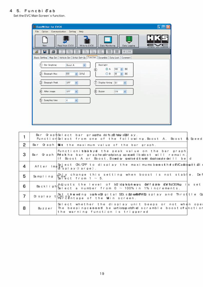
Set the EVC Main Screen's function.
4-5.� [Function] Tab
Select bar graph display data of the EVC display.Select from one of the following.Boost A, Boost B,Speed,RPM,or Throttle.
Set the maximum value of the bar graph.
Function that displays the peak value on the bar graph. If the bar graph drops, a cell depicting peak boost will remain.If Boost A or Boost B was selected, only positive boost will be displayed.
Select ON/OFF to display the maximum boost for about 3 seconds on the EVC digital display(large).
Only change this setting when boost is not stable. Defaut setting is set to 4.Select from 1 ̃ 5.
Adjusts the level of brightness of the EVC display. Defaut setting is set to 100%/30%. Select a number from 0 ̃ 100% in 1% increments.
Set the drawing speed of Digital Display (L・S), Speed/RPM Display and Throttle Opening Percentage of the Main screen.
Select whether the display unit beeps or not when operating it. The beeping sound cannot be stopped during the scramble boost function is triggered or the warning function is triggered.
Bar GraphFunction
Bar Graph Max
Bar Graph Peak
After Image
Sampling Time
Backlight
Display timing
Buzzer
20
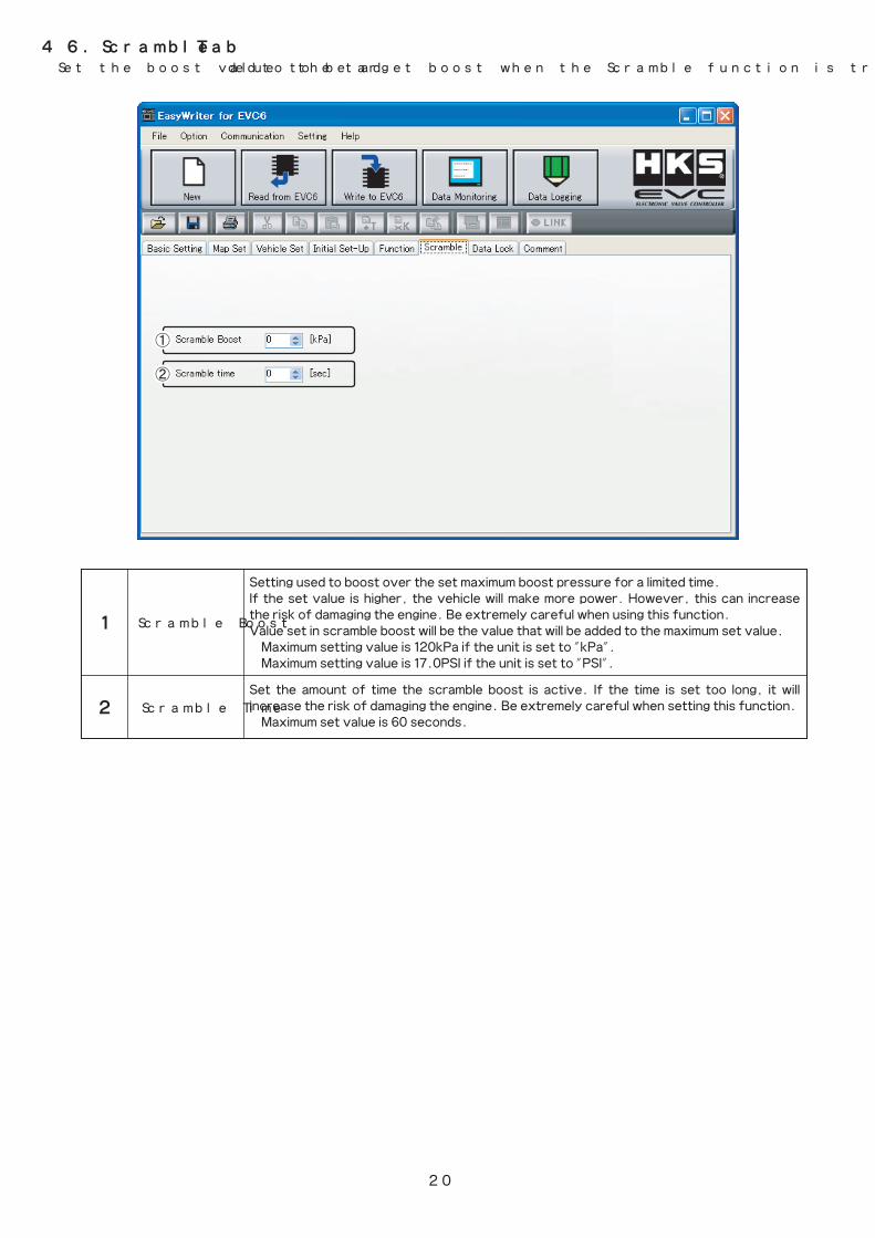
Set the boost value to be added to the target boost when the Scramble function is triggered.
4-6.�[Scramble] Tab
Setting used to boost over the set maximum boost pressure for a limited time.If the set value is higher, the vehicle will make more power. However, this can increase the risk of damaging the engine. Be extremely careful when using this function.Value set in scramble boost will be the value that will be added to the maximum set value. Maximum setting value is 120kPa if the unit is set to "kPa". Maximum setting value is 17.0PSI if the unit is set to "PSI".
Set the amount of time the scramble boost is active. If the time is set too long, it will �increase the risk of damaging the engine. Be extremely careful when setting this function. Maximum set value is 60 seconds.
Scramble Boost
Scramble Time
21
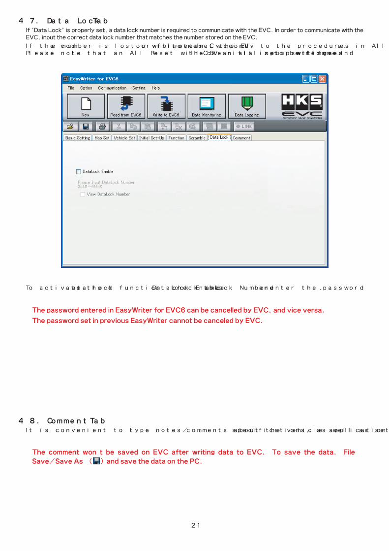
※The password entered in EasyWriter for EVC6 can be cancelled by EVC, and vice versa.
※The password set in previous EasyWriter cannot be canceled by EVC.
If "Data Lock" is properly set, a data lock number is required to communicate with the EVC. In order to communicate with the EVC, input the correct data lock number that matches the number stored on the EVC.
If the code number is lost or forgotten, you will need to reset the EVC accordinly to the procedures in All Reset Mode. Please note that an All Reset will clear all input settings and the EVC's initial setup will need to be redone.
To activate the data lock function, check the “DataLock Enable” and “Lock Number” and enter the password.
4-7.� [Data Lock] Tab
It is convenient to type notes/comments about the vehicle application and specifications, as well as setting information.
4-8.� [Comment] Tab
※The comment won’t be saved on EVC after writing data to EVC. To save the data, 「File→
Save/Save As」 ( ) and save the data on the PC.
22
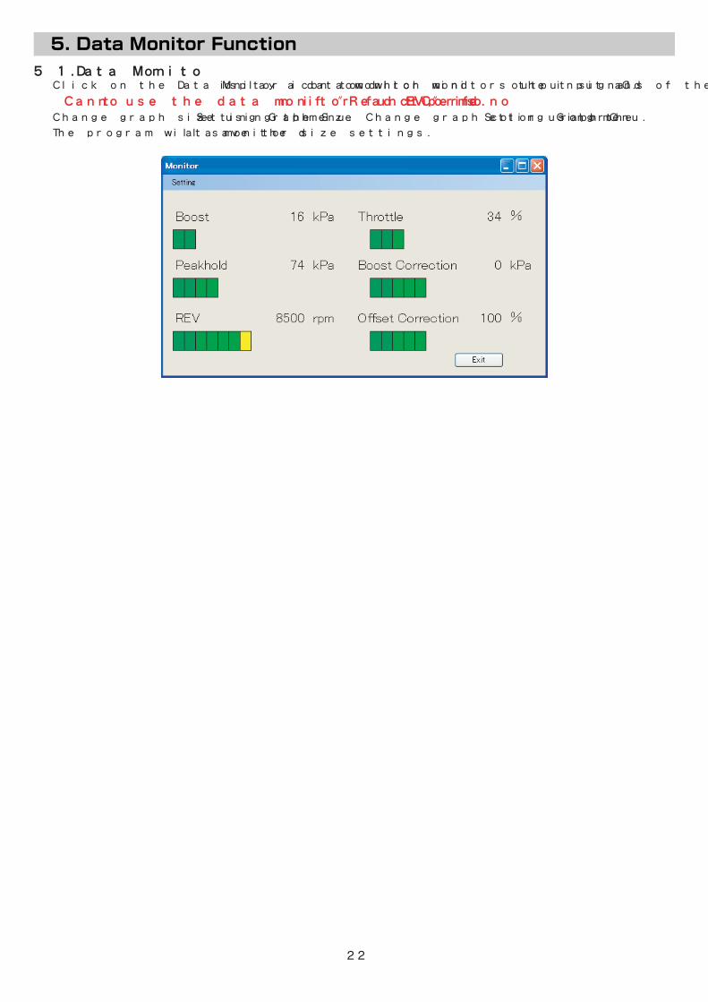
5-1.�Data Monitor� Click on the Data Monitor icon to display a data monitor window which monitors the input and output signals of the EVC.
� ※Cannot use the data monitor function if "Read EVC" is not performed. � Change graph size using the 「Setting→Graph Size」 menu. Change graph color using the 「Setting→Graph Color」 menu.
� The program will save the data monitor size settings.

23
6-1.�Data Log� Click the Data Log icon to display a data log window as shown below.
Display a list of log files to open. Files that can be opened will have a file extension of ".LE6".
Save all the log data being displayed. Saved files will have a file extension of ".LE6". The data log file can also be saved as a text file by selecting ".txt" in the "Save As Type" section of the save dialog window.
Minimize the time axis display of the log data.
Maximize the time axis display of the log data.
Open a log display setting window as shown below. Select display settings in this data log window.
Display the data monitor window and start logging. The parameters displayed in the log monitor window will be the parameters logged. Place markings by pressing the space bar on the keyboard while logging.Press the ESC key or Exit button to finish logging.
※Data logging will not start unless the "Read EVC" process is completed.
Current graph range can be printed.
・Select display settings in this data log window. ・The display/hide, color, maximum/minimum range of
an item can be displayed by selecting an item from the list on the left.
・To change the color of the display, click on the "Color" panel to open a dialog box to list the available colors.
・Input values in the "Maximum" and "Minimum" column to set the desired maximum and minimum display area.
・To change the color of the background, click on the "Background Color" panel to open a dialog box to list the available colors.
・Click OK to complete setup.
Display Setting
Open Log File
Save Log File
Minimize
Maximize
Start
24
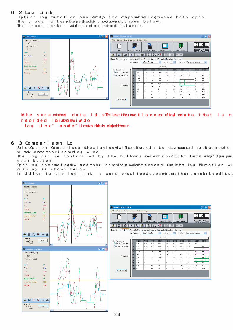
Make sure the correct data is selected. This function will execute even for log data that is not
recorded in the display window.
"Log Link" and "Link Mode" cannot be used together.
6-2.�Log Link� 「Option→Log Link」 function can only be used when the map window and data log window are both open. � The trace marker can be displayed on the data log window as shown below. � The trace marker will be colored green in this instance.
6-3.�Comparison Log� Select 「Option→Comparison Log」 to display a data log window. The log data can be compared by opening both the data log� window and comparison log window. � The log can be controlled by the buttons on the bottom left of the window. Refer to "6-1. Data Log"(page 21) for details of � each button.� Opening the map, data log window, and comparison log windows together and executing the 「Option→Log Link」 function will � display as shown below.� In addition to the log link, a purple-colored trace marker will be displayed for use with the comparison log.

25
7-1.�Display Comparison File/Paste from Comparison File� Select 「Option→Open Comparison File」 to open a dialog selection of the file(s) to be compared. � Select the comparison file to display as shown below.
This function is simply a comparison of values on the maps. These values will be displayed regard-
less of the axis values being used on the edit map and comparison map.
� The top section of each cell indicates the edit map and the bottom indicates the comparison file map. � Yellow-colored cells indicate that the edit map value is greater than the comparison map value. Conversely, light blue-colored � cells indicate that the edit map value is less than the comparison map value. White-colored cells indicate that the values are � equal.
� 「Option→Paste from Comparison」 can be used in "Open Comparison File". � Select 「Option→Paste from Comparison」 to paste the comparison data onto the edit map.
� Cannot compare EVC6's map with EVC6-IR/EVC6-IR 2.4's map.
26
8-2.�COM Port� Select 「Setting→EasyWriter Setting→COM Port」 to select the COM port to connect the EVC. Usually, the port is selected by � “Auto”, however when the EVC is not recognized, select the port to connect the communication cable by “Manual”.
8-3.�Language� Select 「Setting→Language」 to select from "Japanese" or "English".
8-4.�About� Select 「Help→About EasyWriter」 to display a dialog box with current version information. EasyWriter version, display � version, and valve version can be confirmed. � However, the display version and valve version will only be viewable with the EVC connected.
8-1.�All Reset� Select 「Communication→All Reset」 to reset all data including the EVC data lock setting. � All saved settings and data will be deleted as well.