Embed Size (px)
Citation preview
REVISION DESCRIPTION: 1) Page: 12-03 REV 1: Step 1: and Figure 1: Final-Drill s.b. Match-Drill. Step 4: Updated flox mixture description to match later description (removed "peanut butter-like" description). Page 12-07 REV 1: Step 2: Added "Match-Drill #40" before "Final-Drill #30" Step 4: Moved "machine countersink" to beginning of second sentence and deleted "Deburr" Page 12-08 REV 1: In Figure 1 moved forward bend to better match installation with empennage fairing. Page 12-09 REV 1: Step 1: Added "Adjust the bends of the empennage gap cover if/as required to achieve a good fit." Step 2: Added "...and cleco..." aft "Match-Drill" 2) Page 12-10 REV 1: Page completely redone, new instructions and images Page 12-11 REV 1: Complete re-write Page 12-12 REV 1: Complete re-write Page 12-13 REV 1: Complete re-write Page 12-14 REV 1: Was page 10 Page 12-15 REV 0: Was page 11 Page 12-16 REV 0: Was page 12

PAGEREVISION:DATE:
VAN'S AIRCRAFT, INC.
PARTICIPANTS:
04/15/13 0 RV-14
DATE OF COMPLETION:
12-01
SECTION 12:EMPENNAGE
FAIRINGSF-01496
EMPENNAGEFAIRING
VS-909VERTICAL
STABILIZER TIP
R-909RUDDER TIP
HS-910HORIZONTALSTABILIZERTIP FAIRING
E-912ELEVATORTIP FAIRING
R-911RUDDERBOTTOMFAIRING
R-00911BRUDDERFAIRINGDOUBLER
VERTICALSTABILIZERASSEMBLY
TAILCONEASSEMBLY
HS-910HORIZONTAL
STABILIZERTIP FAIRING
E-912ELEVATOR
TIP FAIRING
ELEVATORASSEMBLY
RUDDERASSEMBLY
F-14111-LEMPENNAGEGAP COVER
PAGE REVISION: DATE:
VAN'S AIRCRAFT, INC.
04/15/13PAGE 12-02 RV-14 REVISION: 0 DATE:
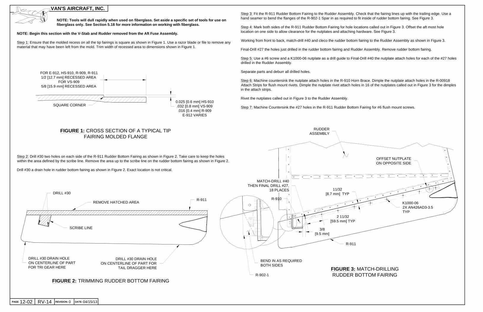
FOR E-912, HS-910, R-909, R-9111/2 [12.7 mm] RECESSED AREA
FOR VS-9095/8 [15.9 mm] RECESSED AREA
FIGURE 1: CROSS SECTION OF A TYPICAL TIPFAIRING MOLDED FLANGE
SQUARE CORNER
NOTE: Tools will dull rapidly when used on fiberglass. Set aside a specific set of tools for use on fiberglass only. See Section 5.18 for more information on working with fiberglass.
NOTE: Begin this section with the V-Stab and Rudder removed from the Aft Fuse Assembly.
Step 1: Ensure that the molded recess on all the tip fairings is square as shown in Figure 1. Use a razor blade or file to remove anymaterial that may have been left from the mold. Trim width of recessed area to dimensions shown in Figure 1.
0.025 [0.6 mm] HS-910.032 [0.8 mm] VS-909.016 [0.4 mm] R-909
E-912 VARIES
R-911REMOVE HATCHED AREA
SCRIBE LINE
DRILL #30
Step 2: Drill #30 two holes on each side of the R-911 Rudder Bottom Fairing as shown in Figure 2. Take care to keep the holeswithin the area defined by the scribe line. Remove the area up to the scribe line on the rudder bottom fairing as shown in Figure 2.
Drill #30 a drain hole in rudder bottom fairing as shown in Figure 2. Exact location is not critical.
FIGURE 2: TRIMMING RUDDER BOTTOM FAIRING
Step 3: Fit the R-911 Rudder Bottom Fairing to the Rudder Assembly. Check that the fairing lines up with the trailing edge. Use ahand seamer to bend the flanges of the R-902-1 Spar in as required to fit inside of rudder bottom fairing. See Figure 3.
Step 4: Mark both sides of the R-911 Rudder Bottom Fairing for hole locations called out in Figure 3. Offset the aft most holelocation on one side to allow clearance for the nutplates and attaching hardware. See Figure 3.
Working from front to back, match-drill #40 and cleco the rudder bottom fairing to the Rudder Assembly as shown in Figure 3.
Final-Drill #27 the holes just drilled in the rudder bottom fairing and Rudder Assembly. Remove rudder bottom fairing.
Step 5: Use a #6 screw and a K1000-06 nutplate as a drill guide to Final-Drill #40 the nutplate attach holes for each of the #27 holesdrilled in the Rudder Assembly.
Separate parts and deburr all drilled holes.
Step 6: Machine countersink the nutplate attach holes in the R-910 Horn Brace. Dimple the nutplate attach holes in the R-00918Attach Strips for flush mount rivets. Dimple the nutplate rivet attach holes in 16 of the nutplates called out in Figure 3 for the dimplesin the attach strips.
Rivet the nutplates called out in Figure 3 to the Rudder Assembly.
Step 7: Machine Countersink the #27 holes in the R-911 Rudder Bottom Fairing for #6 flush mount screws.
3/8[9.5 mm]
11/32[8.7 mm] TYP
2 11/32[59.5 mm] TYP
RUDDERASSEMBLY
FIGURE 3: MATCH-DRILLINGRUDDER BOTTOM FAIRING
R-911
MATCH-DRILL #40THEN FINAL DRILL #27,
18 PLACES
OFFSET NUTPLATEON OPPOSITE SIDE
R-910K1000-062X AN426AD3-3.5TYP
DRILL #30 DRAIN HOLEON CENTERLINE OF PARTFOR TRI GEAR HERE
DRILL #30 DRAIN HOLEON CENTERLINE OF PART FOR
TAIL DRAGGER HERE
BEND IN AS REQUIREDBOTH SIDES
R-902-1

PAGEREVISION:DATE:
VAN'S AIRCRAFT, INC.
FIGURE 2: ATTACHING RUDDER FAIRING DOUBLER
Step 2: Remove hatched area of the R-911 Rudder Bottom Fairing asshown in Figure 2. Drill several holes around the inside of the traced line,but stop short of the line traced in Step 1. Finish removing the material upto the traced line with sandpaper wrapped around a round object.
Step 3: Use coarse sandpaper, 60 grit works well, to roughen the surface of the R-911 Rudder Bottom Fairing and the facingsurface of the R-00911B Rudder Fairing Doubler.
Clean both surfaces well with a solvent such as denatured alcohol.
Step 4: Mix a small batch of epoxy resin and add flox to a smooth consistency that will not drip, but is not too stiff to sag when themixing cup is tipped from side to side. Spread this mixture on the roughened surface of the R-911 Rudder bottom Fairing.
Install the R-00911B Rudder Fairing Doubler with the rivets called out in Figure 2. There should be enough of the epoxy resin floxmixture between the parts to come up to, or just beyond, the adjacent edges of the parts. These edges can be sanded to a smoothfinish after curing.
Run a drill bit through the top and bottom holes left open for later attachment of tail light (see Figure 1 for drill size). Clean bit beforeepoxy cures.
Allow assembly to cure before sanding or installing the rudder bottom fairing.
Step 5: Tap 4-40 the holes for light mounting screws (screws installed in Section OP-56) as shown in Figure 2.
DATE: 12-03103/18/15 REVISION: RV-14 PAGE
REMOVE HATCHED AREA
ROUGHEN SURFACE
CS4-4,2 PLACES
R-00911B
R-911
R-00911BR-911
NOTE: The steps on this page apply only if installing a tail light. Detailed tail light installation instructions are supplied inSection OP-56 Tail Lighting. If not installing the tail light, skip to Page 12-04.
Step 1: Center the R-00911B Rudder Fairing Doubler on the aft end of the R-911 Bottom Rudder Fairing as shown in Figure 1.Tape in place.
Match-Drill #30 and cleco the holes called out in Figure 1. Match-Drill the #43 holes called out in Figure 1.
Use a marker to trace around the opening in the rudder fairing doubler. Remove the rudder fairing doubler, deburr, and machinecountersink as shown in Figure 1.
MATCH-DRILL #30MACHINE COUNTERSINK 120°
MATCH-DRILL #43
FIGURE 1: FITTING RUDDER FAIRING DOUBLER
TRACE AROUNDTHE INSIDE OFTHIS OPENING
TAP FOR 4-40FLUSH MOUNT SCREW,2 PLACES

PAGE REVISION: DATE:
VAN'S AIRCRAFT, INC.
03/18/15PAGE 12-04 RV-14 REVISION: 1 DATE:
FIGURE 3: RUDDER BOTTOM FAIRING
Step 3: Remove hatched area of the R-911 Rudder Bottom Fairing as shown in Figure 3, but stop short of the line traced in Step 2.Finish removing the material up to the traced line with a sanding block.
REMOVEHATCHED
AREA
R-911
NOTE: Steps 4-7 see Page 12-06 Figure 2, 3 and 4 for similar fabrication process.
Step 4: Cut two pieces of glass fabric large enough to fit over the opening created in the R-911 Rudder Bottom Fairing. Glass fabricshould be oversized to allow for trimming and sanding later.
Coat a piece of scrap aluminum sheet with wax (candle wax will work) to use as a form for the fiberglass patch. Lay up the twolayers of glass fabric using epoxy resin. Apply peel ply or similar material over the patch for a good surface finish.
Allow patch to cure flat, then remove peel ply fabric. The patch should pop off of the aluminum sheet easily when the aluminum isgently flexed.
Step 5: Place the fiberglass patch over the opening cut in the R-911 Rudder Bottom Fairing in Step 3. Trace edge of opening ontopatch piece.
Remove patch and trim the piece, leave a small amount of material beyond the traced line. The edges will be sanded after the partshave bonded together.
Step 6: Sand surface of R-911 Rudder Bottom Fairing where parts meet, and the interior around the opening with coarse sandpaper. Clean all surfaces with a solvent such as denatured alcohol.
Bond the patch to the rudder bottom fairing with a small amount of epoxy resin and allow to set.
Step 7: Cut a piece of glass fabric to fit inside the R-911 Rudder Bottom Fairing. The template used to cut the hole in the rudderbottom fairing has a trace line for the interior fabric that allows for 1/2 inch [12.7 mm] overlap.
Apply a fillet of flox mixture around the interior of the cutout. Place glass fabric layer inside the rudder bottom fairing and bond topatch and rudder bottom fairing with epoxy resin.
Allow rudder bottom fairing to cure fully before sanding patch edges.
NOTE: It is necessary to modify the R-911 Bottom Rudder Fairingto clear the tail spring in tail wheel configurations. Steps on thispage apply only to tail wheel configurations. Skip to Page 12-05for tri-gear configuration.
Step 1: Measure and mark the location shown in Figure 1 on the R-911 Rudder Bottom Fairing. The markshould be located along the center line of the part as shown in Figure 2.
FIGURE 1: MARKING RUDDER BOTTOM FAIRING
FIGURE 2: TEMPLATE PLACEMENT
3 1/8[79.4 mm]
R-911
R-911
ALIGNCENTERLINE
WITH MARK
CENTER TEMPLATEON PART CENTERLINE
TEMPLATE
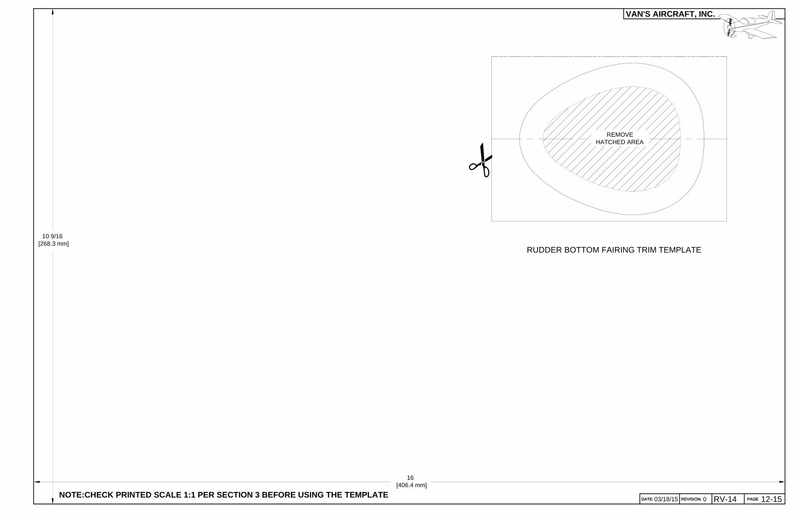
Step 2: Cut and paste the Rudder Bottom Fairing Trim Template (found on Page 12-13) to stiff material such as poster board.Remove hatched area in the center of the template so that it will fit over the end of the R-911 Rudder Bottom Fairing as shown inFigure 2.
Align the template with the mark on the rudder bottom fairing made in Step 1 andcenter the template along the centerline of the part as shown in Figure 2.Trace a line around the rudder bottom fairing where thetemplate meets the fairing.
TRACE INSIDEOF TEMPLATE
MARKHERE
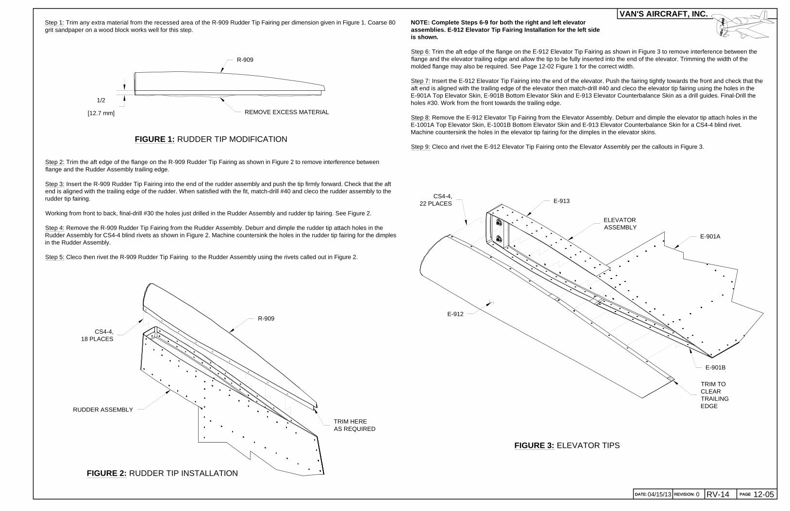
FIGURE 3: ELEVATOR TIPS
PAGEREVISION:DATE:
VAN'S AIRCRAFT, INC.
DATE: 12-05004/15/13 REVISION: RV-14 PAGE
1/2
[12.7 mm]
R-909
REMOVE EXCESS MATERIAL
FIGURE 1: RUDDER TIP MODIFICATION
Step 1: Trim any extra material from the recessed area of the R-909 Rudder Tip Fairing per dimension given in Figure 1. Coarse 80grit sandpaper on a wood block works well for this step.
Step 2: Trim the aft edge of the flange on the R-909 Rudder Tip Fairing as shown in Figure 2 to remove interference betweenflange and the Rudder Assembly trailing edge.
Step 3: Insert the R-909 Rudder Tip Fairing into the end of the rudder assembly and push the tip firmly forward. Check that the aftend is aligned with the trailing edge of the rudder. When satisfied with the fit, match-drill #40 and cleco the rudder assembly to therudder tip fairing.
Working from front to back, final-drill #30 the holes just drilled in the Rudder Assembly and rudder tip fairing. See Figure 2.
Step 4: Remove the R-909 Rudder Tip Fairing from the Rudder Assembly. Deburr and dimple the rudder tip attach holes in theRudder Assembly for CS4-4 blind rivets as shown in Figure 2. Machine countersink the holes in the rudder tip fairing for the dimplesin the Rudder Assembly.
Step 5: Cleco then rivet the R-909 Rudder Tip Fairing to the Rudder Assembly using the rivets called out in Figure 2.
FIGURE 2: RUDDER TIP INSTALLATION
R-909
CS4-4,18 PLACES
RUDDER ASSEMBLY
TRIM HEREAS REQUIRED
NOTE: Complete Steps 6-9 for both the right and left elevatorassemblies. E-912 Elevator Tip Fairing Installation for the left sideis shown.
Step 6: Trim the aft edge of the flange on the E-912 Elevator Tip Fairing as shown in Figure 3 to remove interference between theflange and the elevator trailing edge and allow the tip to be fully inserted into the end of the elevator. Trimming the width of themolded flange may also be required. See Page 12-02 Figure 1 for the correct width.
Step 7: Insert the E-912 Elevator Tip Fairing into the end of the elevator. Push the fairing tightly towards the front and check that theaft end is aligned with the trailing edge of the elevator then match-drill #40 and cleco the elevator tip fairing using the holes in theE-901A Top Elevator Skin, E-901B Bottom Elevator Skin and E-913 Elevator Counterbalance Skin as a drill guides. Final-Drill theholes #30. Work from the front towards the trailing edge.
Step 8: Remove the E-912 Elevator Tip Fairing from the Elevator Assembly. Deburr and dimple the elevator tip attach holes in theE-1001A Top Elevator Skin, E-1001B Bottom Elevator Skin and E-913 Elevator Counterbalance Skin for a CS4-4 blind rivet.Machine countersink the holes in the elevator tip fairing for the dimples in the elevator skins.
Step 9: Cleco and rivet the E-912 Elevator Tip Fairing onto the Elevator Assembly per the callouts in Figure 3.
TRIM TOCLEARTRAILINGEDGE
CS4-4,22 PLACES
E-912
ELEVATORASSEMBLY
E-913
E-901A
E-901B

PAGE REVISION: DATE:
VAN'S AIRCRAFT, INC.
04/15/1312-06 RV-14 REVISION:REVISION: 0 DATE:DATE:
NOTE: Complete Steps on this page for both sides of theHorizontal Stabilizer Assembly.
NOTE: Temporarily attach the Elevator Assembly to the Horizontal Stabilizer Assembly for thefollowing steps. See Section 11 for assembly instructions.
Step 1: Trim the width of the molded flange on the HS-910 Horizontal Stabilizer Tip Fairing if required to meet the dimensions givenon Page 12-02 Figure 1. Progressively trim away the aft edge of the horizontal stabilizer tip fairing to leave a minimum 1/8 inch gapbetween the aft edge of the tip fairing and the forward face of the elevator counterbalance arm. Move the elevator to checkclearance at all positions. See Figure 1.
Step 2: Match Drill #40 the HS-910 Horizontal Stabilizer Tip Fairing to the HS-901 Horizontal Stabilizer Skin. Final-Drill #30 the #40holes.
Step 5: Cleco the HS-910 Horizontal Stabilizer Tip Fairing to the Horizontal Stabilizer Assembly. Place the fiberglass patch over theopening in the HS-910 Horizontal Stabilizer Tip Fairing and trace edge of opening onto patch piece.
Remove patch and trim the piece, leave a small amount of material beyond the traced line. The edges will be sanded after the partshave bonded together. See Figure 3 and Figure 4.
Step 6: Sand surface of HS-910 Horizontal Stabilizer Tip Fairing where parts meet, and the interior around the opening with coarsesand paper. Clean all surfaces with a solvent such as denatured alcohol.
Bond the patch to the horizontal stabilizer tip fairing with a small amount of epoxy resin. Secure patch to the fairing with tape andallow to cure.
Step 7: Cut a piece of glass fabric to fit inside the HS-910 Horizontal Stabilizer Tip Fairing. Allow for 1/2 inch [12.7 mm] overlap.
Apply a fillet of flox mixture around the interior where the two pieces meet. Place this glass fabric layer inside the horizontalstabilizer tip fairing and bond to the patch and the horizontal stabilizer tip fairing with epoxy resin.
Allow horizontal stabilizer tip fairing to cure fully before sanding patch edges.
APPROX.6
[152.6 mm]
1/8 [3.3 mm] MINIMUM
FIGURE 1: CREATING GAP
HS-910
FIGURE 2: FIBERGLASS FABRICATION(LEFT AND RIGHT LAY-UPS SHOWN)
MATCH-DRILL #40FINAL-DRILL #30
TYP
Step 3: Take a piece of scrap aluminum sheet large enough to fit over the aft opening of the HS-910 Horizontal Stabilizer TipFairing. Bend scrap sheet to fit the angle of the horizontal stabilizer tip fairing aft edge (exact angle is not critical).
Place the horizontal stabilizer tip on the aluminum scrap sheet and trace the edge onto the sheet.Coat the scrap aluminum sheetwith wax (candle wax will work).
Step 4: Using the traced area as a guide, cut two layers of glass fabric larger than traced area to allow for trimming and sandinglater. Lay up two layers of glass fabric using epoxy resin on the bent sheet. Apply peel ply or similar material over the patch for agood surface finish.
Allow patch to cure, then remove peel ply fabric. The patch should pop off of the aluminum sheet easily when the aluminum isgently flexed. See Figure 2.
RIGHT
FWD
FIGURE 3: FIBERGLASS PATCH FIGURE 4: TIP FAIRING MODIFICATION
Step 8: Deburr and dimple the horizontal stabilizer tip attach holes in the HS-901 Horizontal Stabilizer Skin for CS4-4 blind rivets.Machine countersink the holes in the HS-910 Horizontal Stabilizer Tip Fairing for the dimples in the horizontal stabilizer skins.
Step 9: Cleco and rivet the HS-910 Horizontal Stabilizer Tip Fairingto the Horizontal Stabilizer Assembly. See Figure 5.
FIGURE 5: HORIZONTAL STABILIZER TIP FAIRING INSTALLATION
CS4-4,8 PLACES
HS-910
HS-901
HORIZONTAL STABILIZERASSEMBLY
ELEVATOR ASSEMBLY
PAGEREVISION:DATE:
VAN'S AIRCRAFT, INC.
DATE: 12-07103/18/15 REVISION: RV-14 PAGE
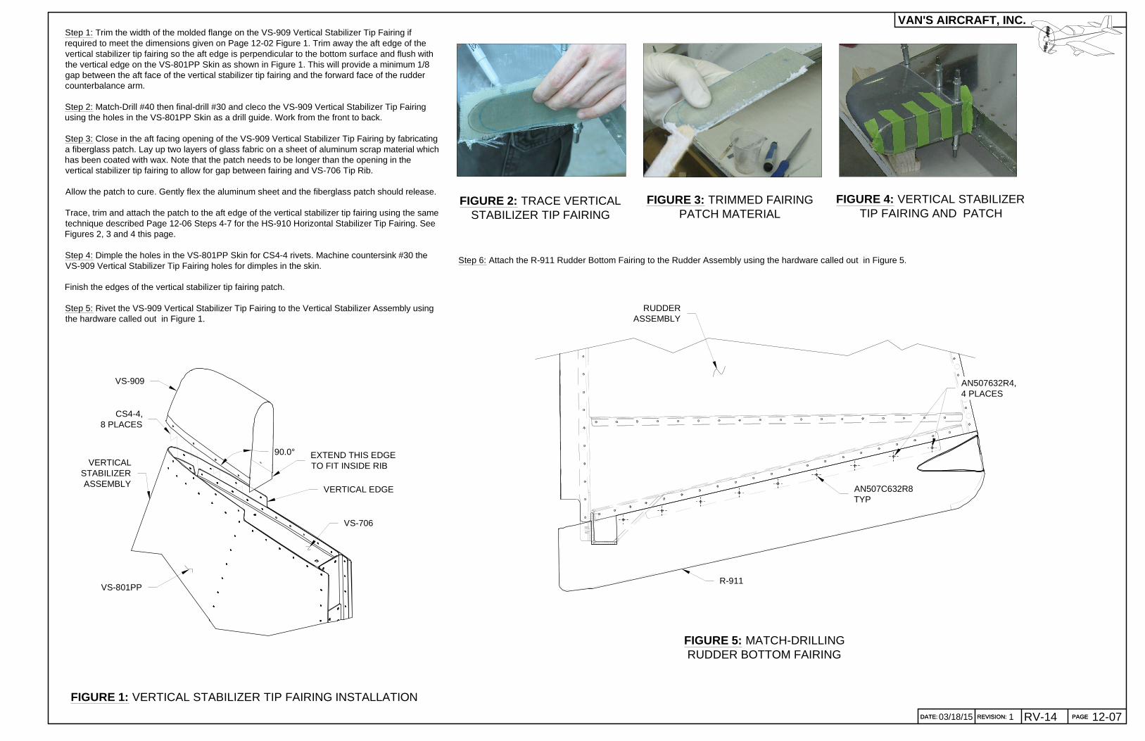
FIGURE 1: VERTICAL STABILIZER TIP FAIRING INSTALLATION
Step 1: Trim the width of the molded flange on the VS-909 Vertical Stabilizer Tip Fairing ifrequired to meet the dimensions given on Page 12-02 Figure 1. Trim away the aft edge of thevertical stabilizer tip fairing so the aft edge is perpendicular to the bottom surface and flush withthe vertical edge on the VS-801PP Skin as shown in Figure 1. This will provide a minimum 1/8gap between the aft face of the vertical stabilizer tip fairing and the forward face of the ruddercounterbalance arm.
Step 2: Match-Drill #40 then final-drill #30 and cleco the VS-909 Vertical Stabilizer Tip Fairingusing the holes in the VS-801PP Skin as a drill guide. Work from the front to back.
Step 3: Close in the aft facing opening of the VS-909 Vertical Stabilizer Tip Fairing by fabricatinga fiberglass patch. Lay up two layers of glass fabric on a sheet of aluminum scrap material whichhas been coated with wax. Note that the patch needs to be longer than the opening in thevertical stabilizer tip fairing to allow for gap between fairing and VS-706 Tip Rib.
Allow the patch to cure. Gently flex the aluminum sheet and the fiberglass patch should release.
Trace, trim and attach the patch to the aft edge of the vertical stabilizer tip fairing using the sametechnique described Page 12-06 Steps 4-7 for the HS-910 Horizontal Stabilizer Tip Fairing. SeeFigures 2, 3 and 4 this page.
Step 4: Dimple the holes in the VS-801PP Skin for CS4-4 rivets. Machine countersink #30 theVS-909 Vertical Stabilizer Tip Fairing holes for dimples in the skin.
Finish the edges of the vertical stabilizer tip fairing patch.
Step 5: Rivet the VS-909 Vertical Stabilizer Tip Fairing to the Vertical Stabilizer Assembly usingthe hardware called out in Figure 1.
VS-801PP
VERTICAL EDGE
VS-909
VERTICALSTABILIZERASSEMBLY
CS4-4,8 PLACES
EXTEND THIS EDGETO FIT INSIDE RIB
VS-706
FIGURE 3: TRIMMED FAIRINGPATCH MATERIAL
FIGURE 2: TRACE VERTICALSTABILIZER TIP FAIRING
FIGURE 4: VERTICAL STABILIZERTIP FAIRING AND PATCH
90.0°
RUDDERASSEMBLY
FIGURE 5: MATCH-DRILLINGRUDDER BOTTOM FAIRING
R-911
AN507C632R8TYP
Step 6: Attach the R-911 Rudder Bottom Fairing to the Rudder Assembly using the hardware called out in Figure 5.
AN507632R4,4 PLACES
PAGE REVISION: DATE:
VAN'S AIRCRAFT, INC.
03/18/1512-08 RV-14 REVISION:REVISION: 1 DATE:DATE:
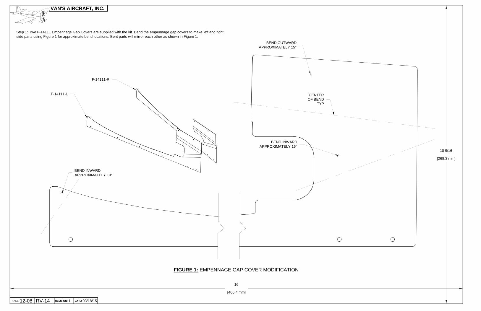
FIGURE 1: EMPENNAGE GAP COVER MODIFICATION
Step 1: Two F-14111 Empennage Gap Covers are supplied with the kit. Bend the empennage gap covers to make left and rightside parts using Figure 1 for approximate bend locations. Bent parts will mirror each other as shown in Figure 1.
10 9/16
[268.3 mm]
16
[406.4 mm]
BEND INWARDAPPROXIMATELY 10°
BEND INWARDAPPROXIMATELY 16°
BEND OUTWARDAPPROXIMATELY 15°
F-14111-L
F-14111-R
CENTEROF BEND
TYP

PAGEREVISION:DATE:
VAN'S AIRCRAFT, INC.
DATE: 12-09103/18/15 REVISION: RV-14 PAGE
FIGURE 2: DRILLING EMPENNAGE GAP COVERS(SHOWN DRILLING LEFT, RIGHT SIDE IS MIRRORED)
MATCH-DRILL #40FROM OPPOSITE SIDE
FWD
UP
LEFT
F-14111-L
HORIZONTALSTABILIZERASSEMBLY
VERTICALSTABILIZERASSEMBLY
NOTE: Attach the Vertical Stabilizer Assembly to the Aft Fuse Assembly for the following steps. See Section 11 forassembly instructions.
Step 1: Secure the F-14111-L Empennage Gap Cover to the Empennage Assembly using the hardware shown in Figure 1. Adjustthe bends of the empennage gap cover if/as required to achieve a good fit.
Step 2: The bottom edge of the Vertical Stabilizer Assembly has a series of holes left open for the F-01496 Empennage Fairing andF-14111-L and F-14111-R Empennage Gap Covers. Match-Drill #40 and cleco the left empennage gap cover using a 12" extensionbit as shown in Figures 1 and 2. Remove the left side empennage gap cover.
Screw the right side empennage gap cover to the Empennage Assembly and match-drill #40 and cleco the holes in the samemanner as the left. See Figure 2. Reinstall the left side empennage gap cover.
FIGURE 1: EMPENNAGE GAPCOVER MODIFICATION
F-14111-L
EMPENNAGEASSEMBLY
AN526C632R4
AN526C632R65 PLACES/SIDE

PAGE REVISION: DATE:
VAN'S AIRCRAFT, INC.
03/18/1512-10 RV-14 REVISION:REVISION: 1 DATE:DATE:
NOTE: The F-01496 Empennage Fairing is supplied in the Finish Kit.
NOTE: Use a slow turning drill when blind drilling to prevent the bit from wandering. Press the fairingtightly against metal surface before drilling.
Step 1: Trim the F-01496 Empennage Fairing to 1/8 [3.2 mm] outside of the scribe line as shown in Figure 1.
Step 2: Apply tape to the aft upper inner surface of empennage fairing corners to prevent scratching the Vertical Stabilizer Assemblyduring the fitting process.
Step 3: Hold the empennage fairing in position on the empennage and check for continuous contact between the fairing flanges andthe aircraft skins.
Mark the fairing and sand to remove any thick spots. See Figure 1.
Step 4: Hold fairing in position and check the empennage fairing fit to the leading edges of the Horizontal and Vertical StabilizerAssemblies as shown in Figure 2.
Mark areas of interference and sand to shape as required to match the profile of the fairing to the leading edges.
Step 5: If there is a gap between the Horizontal Stabilizer Assembly leading edge and the empennage fairing that is more than 1/16[1.6 mm] when the Vertical Stabilizer Assembly and fairing are in contact, trim the fairing at the contact point between the VerticalStabilizer Assembly and the empennage fairing as shown in Figure 3.
Recheck the fit, sand if required to achieve a better fit.
It is acceptable to trim to orbeyond the scribe line asrequired to allow the fairing tomove aft into alignment with theHorizontal Stabilizer Assemblyas shown in Figure 2.
FIGURE 1: EMPENNAGE FAIRING TRIM
OFFSET TRIM1/8 [3.2 mm]FROM SCRIBE LINE
MARK THICK AREAS
FIGURE 2: EMPENNAGE FAIRING PLACEMENT
MARK AREASAND SAND TO
FIT AS REQUIRED
F-01496
F-01496
HORIZONTALSTABILIZERASSEMBLY
MAXIMUM GAP1/16 [1.6 mm]
FIGURE 3: EMPENNAGE FAIRING AT VERTICAL STABILIZER
F-01496
VERTICAL STABILIZER ASSEMBLY
SCRIBE LINE
TRIMHERE IF/ASREQUIRED

PAGEREVISION:DATE:
VAN'S AIRCRAFT, INC.
DATE: 12-11103/18/15 REVISION: RV-14 PAGE
Step 1: Place a light inside the Aft Fuselage Assembly to make the holes in the upper portion of the tailcone more visible. Positionthe F-01496 Empennage Fairing on the Empennage Assembly. Once properly positioned, tape the fairing firmly in place.
NOTE: If the F-01496 Empennage Fairing was sanded at the location of a screw attach point, and visibility is hindered,sand the inner surface with 320 grit sandpaper and wet the surface to allow good visibility through the part.
Step 2: Blind-Drill #40 the holes through the empennage fairing starting in the forward most fairing attach holes of the VerticalStabilizer Assembly and the Horizontal Stabilizer Assembly. Work toward the back alternating side to side and clecoing each holeas it is drilled. See Figures 1 & 2.
Step 3: Blind-Drill #27 the holes around the front of the fairing that are common to the aft fuse skins and insert 1/8 clecos.
Final-Drill #27 the #40 holes drilled in Step 2.
Final-Drill #27 the aft upper hole in the F-14111-L & -R Empennage Gap Covers as shown in Figure 2 .
FIGURE 1: EMPENNAGE FAIRING MODIFICATION
BLIND-DRILL #27
AFT FUSEASSEMBLY
F-01496
BLIND DRILL #40,FINAL-DRILL #2710 PLACES
TRIM TOSCRIBE LINETHIS EDGE
FWD
LEFT
FWD
UP
FIGURE 2: EMPENNAGE FAIRING MODIFICATION
BLIND-DRILL #40,FINAL-DRILL #277 PLACES/SIDE
VERTICALSTABILIZERASSEMBLY
F-01496
MAKE FLUSHWITH F-14111
FWD ANDBOTTOM EDGE
MARK FLUSHWITH AFT EDGE
HORIZONTALSTABILIZER
F-14111-R
3/8[9.5 mm]EDGE
DISTANCE
5/16[7.9 mm]EDGE
DISTANCE
5/16[7.9 mm]
EDGE DISTANCE
ALIGN WITHSKIN HERE
HORIZONTALSTABILIZERASSEMBLY FINAL-DRILL #27
AND DIMPLETHIS HOLE
BOTH SIDES
Step 4: Machine countersink the #27 holes in the empennage fairing for#6 flush screws before removing the fairing from the Aft FuselageAssembly. Countersinks that are slightly too shallow are preferred infiberglass.
Step 5: Remove the empennage fairing and empennage gap covers from the Aft Fuselage Assembly.
Step 6: Dimple the upper aft hole in the empennage gap covers for the head of a flush #6 screw. See Figure 2.
Dimple the corresponding holes in the Vertical Stabilizer Assembly as shown in Figure 2. These dimples may be finished with amachine countersink if required to achieve a better final fit with the empennage gap covers.
Step 7: Using a nutplate with a #6 screw screwed through from the back side as a guide pin, match-drill #40 the nutplate attachholes into the Vertical Stabilizer Assembly and Horizontal Stabilizer Assembly. There will be some play between the screw and thehole, make an effort to center the screw in the hole while drilling. Cleco the first hole before drilling the second.

PAGE REVISION: DATE:
VAN'S AIRCRAFT, INC.
03/18/1512-12 RV-14 REVISION:REVISION: 1 DATE:DATE:
NOTE: Removal of the Vertical Stabilizer Assembly will ease thecompletion of the next few steps.
Step 1: Deburr the drilled holes, then machine countersink the nutplate attach holes in the VerticalStabilizer Assembly.
Step 2: Dimple the nutplate attach holes in the Horizontal Stabilizer Assembly. Note that some of the nutplate attach holes will havevery little edge distance on the rib flanges and the dimples will appear to form poorly. At this location the fairing will cover theimperfect dimples.
Step 3: Machine countersink the aft #27 hole on both sides of the Vertical Stabilizer Assembly to accept the dimpled F-14111-L &-R Empennage Gap Covers. See Figure 2.
Step 4: Install all Emp Gap Cover and Emp Fairing attach nutplates to the Vertical Stabilizer Assembly, Horizontal StabilizerAssembly and Aft Fuselage Assembly as shown in Figure 1 & 2.
Dimple nutplates at attach holes as appropriate.
FIGURE 1: EMPENNAGE FAIRING INSTALLATION(TOP VIEW)
AFT FUSEASSEMBLY
F-01496
FWD
LEFTUP
FIGURE 2: EMPENNAGE FAIRING INSTALLATION(SIDE VIEW)
VERTICALSTABILIZERASSEMBLY
F-01496
F-14111-R
HORIZONTALSTABILIZERASSEMBLY
F-01496
3XK1000-062X AN426AD3-3.5AN507C632R6
10XK1000-062X AN426AD3-4AN507C632R6
6 PLACES /SIDEK1000-062X AN426AD3-4AN507C632R6
2 PLACES/SIDE
K1000-062X AN426AD3-3.5
AN507C632R6
MACHINE COUNTERSINKVERTICAL STABILIZER
FOR DIMPLE INEMPENNAGE GAP COVER
Step 5: Reinstall the Vertical Stabilizer Assembly if removed (see Section 11 Page 07-08 for reference).
Attach the Emp Fairing and Gap Covers with screws. Boelube on the screws will ease insertion of the screws. Tighten screws onlyenough to hold the fairing snug to the surface.
Step 6: Mark the aft edges of the F-14111-L & -R Gap Covers where they extend aft of the Vertical Stabilizer Assembly and aftfuselage skins and trim as required to be flush.
MARKAND TRIM
OVERHANG
FWD
TRIM LINEBETWEEN
GAP COVERAND FAIRING

PAGEREVISION:DATE:
VAN'S AIRCRAFT, INC.
DATE: 12-13103/18/15 REVISION: RV-14 PAGE
Step 1: Inspect the F-01496 Empennage Fairing edges for consistent contact with the skins. Mark onthe skin and on the fairing in the areas where gap is occurring.
Step 2: Remove the fairing and adjust the finish trim line for screw hole edge distance as requiredsee Page 12-11 Figures 1 & 2.
Trim the fairing to the scribe lines and/or marked lines around the perimeter.
Sand the trimmed edges smooth and scuff any areas that were marked as having a gap from theunderlying skins.
Clean the surface with compressed air to remove dust.
Step 3: Apply thin cellophane packing tape as a release agent to fuselage, horizontal stabilizer skins,and vertical stabilizer skin in areas where gap was noticed. See Figure 1.
Step 4: Mix epoxy with flox to a smooth consistency that will not drip, but is not too stiff to sag whenthe mixing cup is tipped from side to side.
Smear the flox mixture onto the areas that had gaps. Carefully reinstall the fairing and attach withscrews. Check for epoxy that squeezed out in gapped areas, and press flox mixture in from theoutside if a gap is still apparent. Allow the epoxy to cure.
Step 5: In areas where the edge of the fairing is thicker than desired (possibly at the leading edgeinterfaces) apply tape to the adjacent metal skin for protection and sand fairing to the desired profileand thickness.
Step 6: Remove the fairing.
Use medium grit sandpaper to sand the inner surface of the fairing where it has contact with anymetal skin when installed.
Clean the sanded areas and brush a wet coat of epoxy into the surface to seal in and cover all theweave of the fiberglass. This will prevent the fibers from wearing through the paint and metal skins inservice.
The outer surface of the fairing can now be prepped for finishing as desired and all tape removedfrom the metal skins.
Step 7: Attach the empennage fairing using the hardware called out on Page 12-12 Figures 1 & 2.
FIGURE 1: FILLING GAPS WITH THE EMPENNAGE FAIRING
F-01496
PACKING TAPE
MARK AREASTO BE FILLED

PAGE REVISION: DATE:
VAN'S AIRCRAFT, INC.
03/18/1512-14 RV-14 REVISION:REVISION: 1 DATE:DATE:
FIGURE 2: ELEVATOR TRAVEL
"FULL UP"POSITION
"TRAIL"POSITION
"FULL DOWN"POSITION
30.0°+0.0°-0.5°
25.0°+0.0°-0.5°
FIGURE 1: GAP COVER CLEARANCESOME PARTS NOT SHOWN FOR CLARITY
Step 1: Attach the Elevator Assembly to the Empennage Assembly per instructions in Section 11. Check thatthe F-14111-L and F-1411-R Empennage Gap Covers have the minimum clearance as listed in Figure 1 at alltravel positions as shown in Figure 2. Remove the empennage gap covers and trim (if required) to meet theminimum clearance.
NOTE: Empennage fairing installations are now complete. Final install all empennage assemblies per Section 11. Attachmenthardware must match the callouts for final installation as noted in Section 11.
ELEVATORASSEMBLY
F-14111-L
WD-605-L-1
MINIMUM GAPOF 1/16 [1.6 mm]
PAGEREVISION:DATE:
VAN'S AIRCRAFT, INC.
RUDDER BOTTOM FAIRING TRIM TEMPLATE
DATE: 12-15003/18/15 REVISION: RV-14 PAGE
�16
[406.4 mm]
10 9/16 [268.3 mm]
NOTE:CHECK PRINTED SCALE 1:1 PER SECTION 3 BEFORE USING THE TEMPLATE
REMOVEHATCHED AREA

PAGE REVISION: DATE:
VAN'S AIRCRAFT, INC.
THIS PAGE INTENTIONALLY LEFT BLANK
REVISION:REVISION: DATE:DATE: 03/18/1512-16 RV-14 0