Embed Size (px)
Citation preview
STOL CH750
Zenith Aircraft Company www.zenithair.com
Fin & Rudder Cable Fairing InstallationSection 75-ZA-3, Page 1 of 18
Revision 1.0 (12/3/2010) © 2010 Zenith Aircraft Co.
Section 75-ZA-3 Fin & Rudder Cable Fairing Installation
This manual has been prepared for installation of the Fin and Fairings. This photo assembly manual is intended as a supplement to the drawings. If there is any discrepancy between this manual and the drawings, the drawings supersede this manual. For more information on building standards and allowable tolerances see “Construction Standards for Zenair Light Aircraft” available from Zenith Aircraft Co.
STOL CH750
Zenith Aircraft Company www.zenithair.com
Fin & Rudder Cable Fairing InstallationSection 75-ZA-3, Page 2 of 18
Revision 1.0 (12/3/2010) © 2010 Zenith Aircraft Co.
P/N: 75Z1-5 Rudder Cable Outlet Fairing
It is helpful to use a string or rod to determine the installed angle of the Rudder Cable to position the Fairing. The above photo has a small steel rod on the Rudder Horn running into the Fuselage at the cable outlet.
STOL CH750
Zenith Aircraft Company www.zenithair.com
Fin & Rudder Cable Fairing InstallationSection 75-ZA-3, Page 3 of 18
Revision 1.0 (12/3/2010) © 2010 Zenith Aircraft Co.
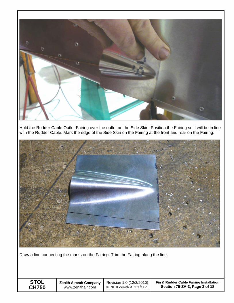
Hold the Rudder Cable Outlet Fairing over the outlet on the Side Skin. Position the Fairing so it will be in line with the Rudder Cable. Mark the edge of the Side Skin on the Fairing at the front and rear on the Fairing.
Draw a line connecting the marks on the Fairing. Trim the Fairing along the line.
STOL CH750
Zenith Aircraft Company www.zenithair.com
Fin & Rudder Cable Fairing InstallationSection 75-ZA-3, Page 4 of 18
Revision 1.0 (12/3/2010) © 2010 Zenith Aircraft Co.
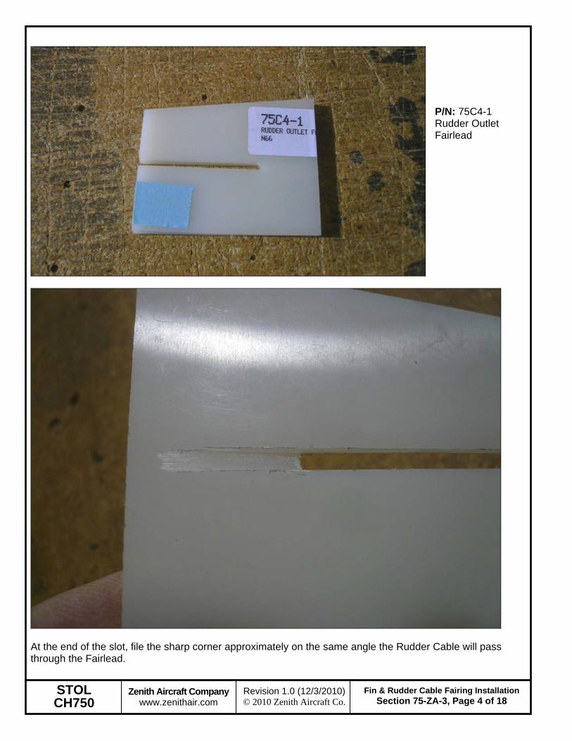
P/N: 75C4-1 Rudder Outlet Fairlead
At the end of the slot, file the sharp corner approximately on the same angle the Rudder Cable will pass through the Fairlead.

STOL CH750
Zenith Aircraft Company www.zenithair.com
Fin & Rudder Cable Fairing InstallationSection 75-ZA-3, Page 5 of 18
Revision 1.0 (12/3/2010) © 2010 Zenith Aircraft Co.
Center the slot in the Fairlead on the outlet of the Fairing. Clamp the Fairlead to the Fairing. Mark the bottom edge of the Fairing on the Fairlead. Mark the top corners of the Fairlead on the top of the Fairing. Then connect the marks on the Fairing.
Mark a line 10mm from the bottom edge of the Fairing and a line 10mm from the top edge of the Fairlead. Layout rivet locations 10mm from each end and one centered between the ends on both the top and bottom.
STOL CH750
Zenith Aircraft Company www.zenithair.com
Fin & Rudder Cable Fairing InstallationSection 75-ZA-3, Page 6 of 18
Revision 1.0 (12/3/2010) © 2010 Zenith Aircraft Co.
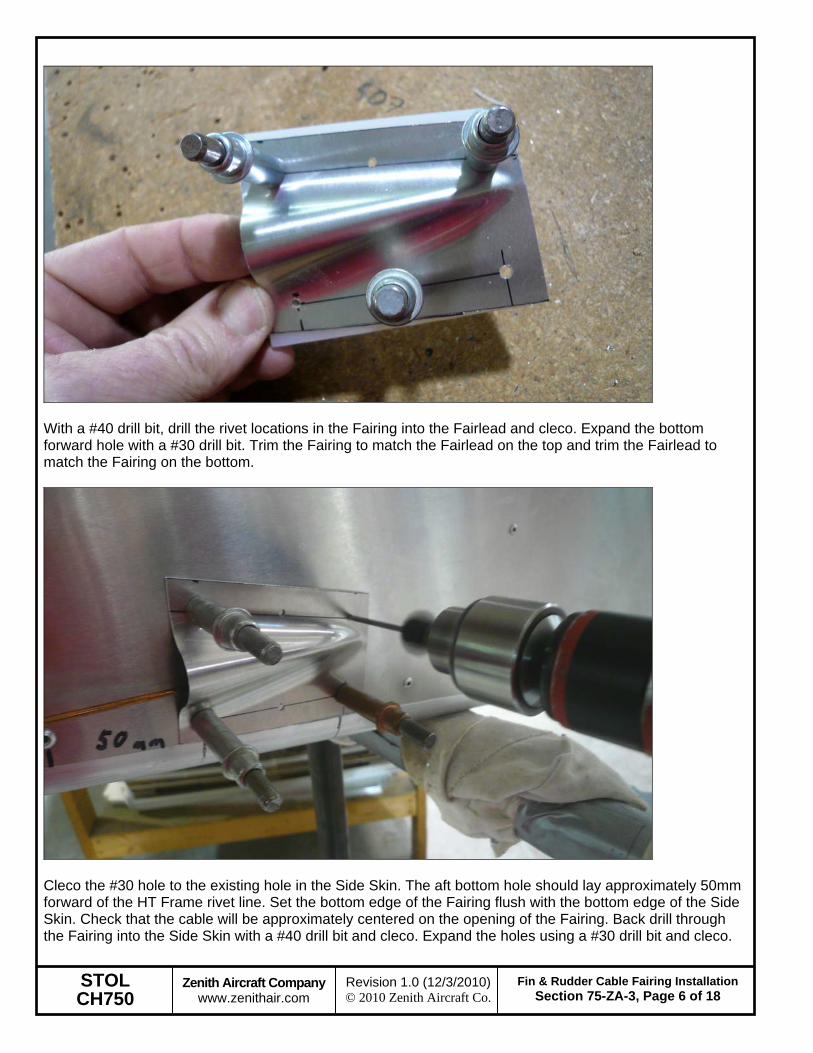
With a #40 drill bit, drill the rivet locations in the Fairing into the Fairlead and cleco. Expand the bottom forward hole with a #30 drill bit. Trim the Fairing to match the Fairlead on the top and trim the Fairlead to match the Fairing on the bottom.
Cleco the #30 hole to the existing hole in the Side Skin. The aft bottom hole should lay approximately 50mm forward of the HT Frame rivet line. Set the bottom edge of the Fairing flush with the bottom edge of the Side Skin. Check that the cable will be approximately centered on the opening of the Fairing. Back drill through the Fairing into the Side Skin with a #40 drill bit and cleco. Expand the holes using a #30 drill bit and cleco.
STOL CH750
Zenith Aircraft Company www.zenithair.com
Fin & Rudder Cable Fairing InstallationSection 75-ZA-3, Page 7 of 18
Revision 1.0 (12/3/2010) © 2010 Zenith Aircraft Co.
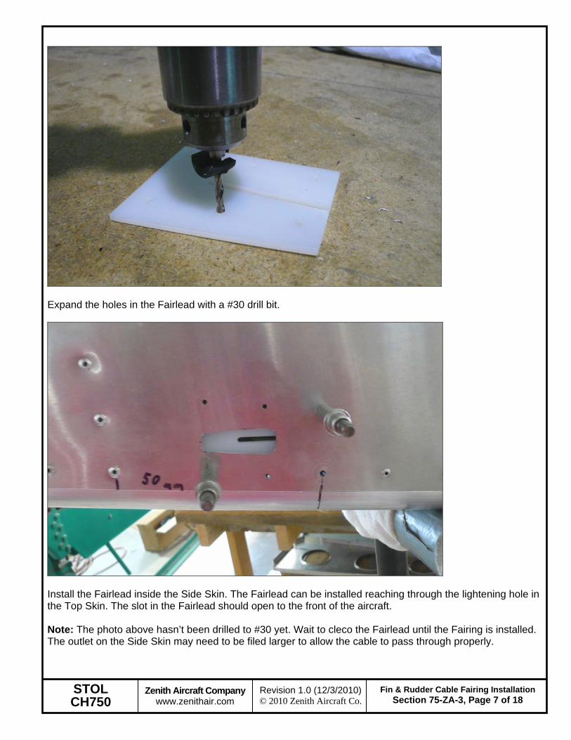
Expand the holes in the Fairlead with a #30 drill bit.
Install the Fairlead inside the Side Skin. The Fairlead can be installed reaching through the lightening hole in the Top Skin. The slot in the Fairlead should open to the front of the aircraft. Note: The photo above hasn’t been drilled to #30 yet. Wait to cleco the Fairlead until the Fairing is installed. The outlet on the Side Skin may need to be filed larger to allow the cable to pass through properly.
STOL CH750
Zenith Aircraft Company www.zenithair.com
Fin & Rudder Cable Fairing InstallationSection 75-ZA-3, Page 8 of 18
Revision 1.0 (12/3/2010) © 2010 Zenith Aircraft Co.
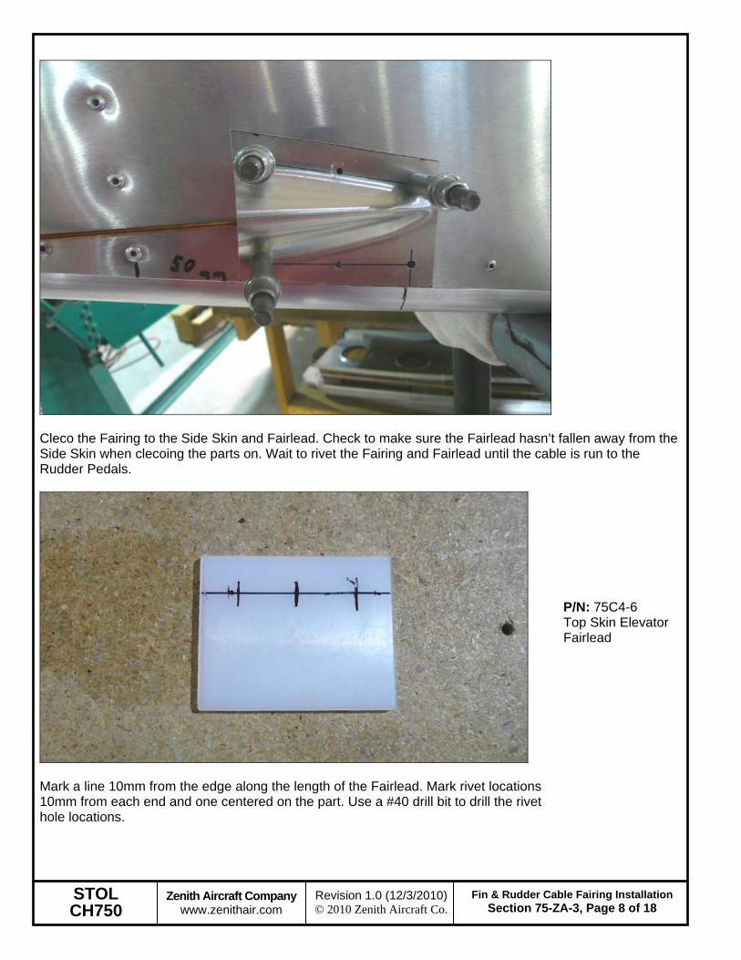
Cleco the Fairing to the Side Skin and Fairlead. Check to make sure the Fairlead hasn’t fallen away from the Side Skin when clecoing the parts on. Wait to rivet the Fairing and Fairlead until the cable is run to the Rudder Pedals.
Mark a line 10mm from the edge along the length of the Fairlead. Mark rivet locations 10mm from each end and one centered on the part. Use a #40 drill bit to drill the rivet hole locations.
P/N: 75C4-6 Top Skin Elevator Fairlead
STOL CH750
Zenith Aircraft Company www.zenithair.com
Fin & Rudder Cable Fairing InstallationSection 75-ZA-3, Page 9 of 18
Revision 1.0 (12/3/2010) © 2010 Zenith Aircraft Co.
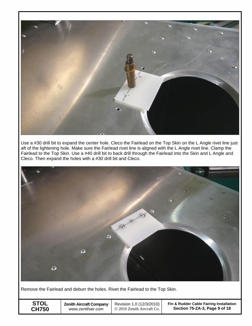
Use a #30 drill bit to expand the center hole. Cleco the Fairlead on the Top Skin on the L Angle rivet line just aft of the lightening hole. Make sure the Fairlead rivet line is aligned with the L Angle rivet line. Clamp the Fairlead to the Top Skin. Use a #40 drill bit to back drill through the Fairlead into the Skin and L Angle and Cleco. Then expand the holes with a #30 drill bit and Cleco.
Remove the Fairlead and deburr the holes. Rivet the Fairlead to the Top Skin.
STOL CH750
Zenith Aircraft Company www.zenithair.com
Fin & Rudder Cable Fairing InstallationSection 75-ZA-3, Page 10 of 18
Revision 1.0 (12/3/2010) © 2010 Zenith Aircraft Co.
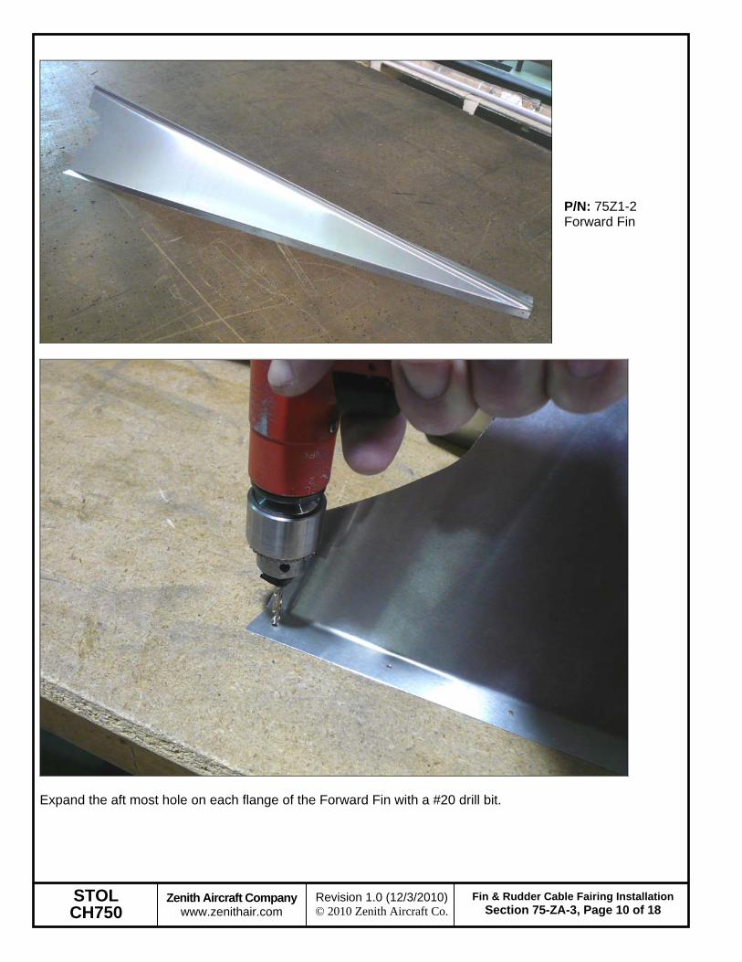
P/N: 75Z1-2 Forward Fin
Expand the aft most hole on each flange of the Forward Fin with a #20 drill bit.
STOL CH750
Zenith Aircraft Company www.zenithair.com
Fin & Rudder Cable Fairing InstallationSection 75-ZA-3, Page 11 of 18
Revision 1.0 (12/3/2010) © 2010 Zenith Aircraft Co.
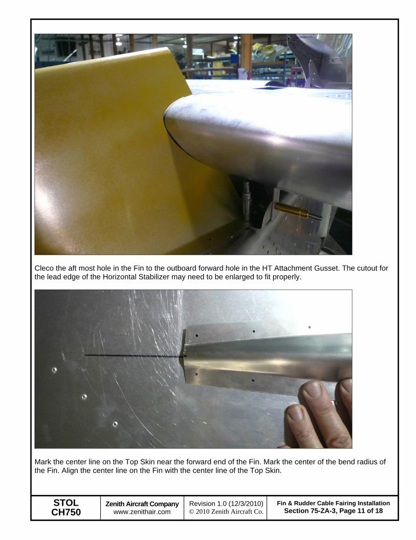
Cleco the aft most hole in the Fin to the outboard forward hole in the HT Attachment Gusset. The cutout for the lead edge of the Horizontal Stabilizer may need to be enlarged to fit properly.
Mark the center line on the Top Skin near the forward end of the Fin. Mark the center of the bend radius of the Fin. Align the center line on the Fin with the center line of the Top Skin.
STOL CH750
Zenith Aircraft Company www.zenithair.com
Fin & Rudder Cable Fairing InstallationSection 75-ZA-3, Page 12 of 18
Revision 1.0 (12/3/2010) © 2010 Zenith Aircraft Co.
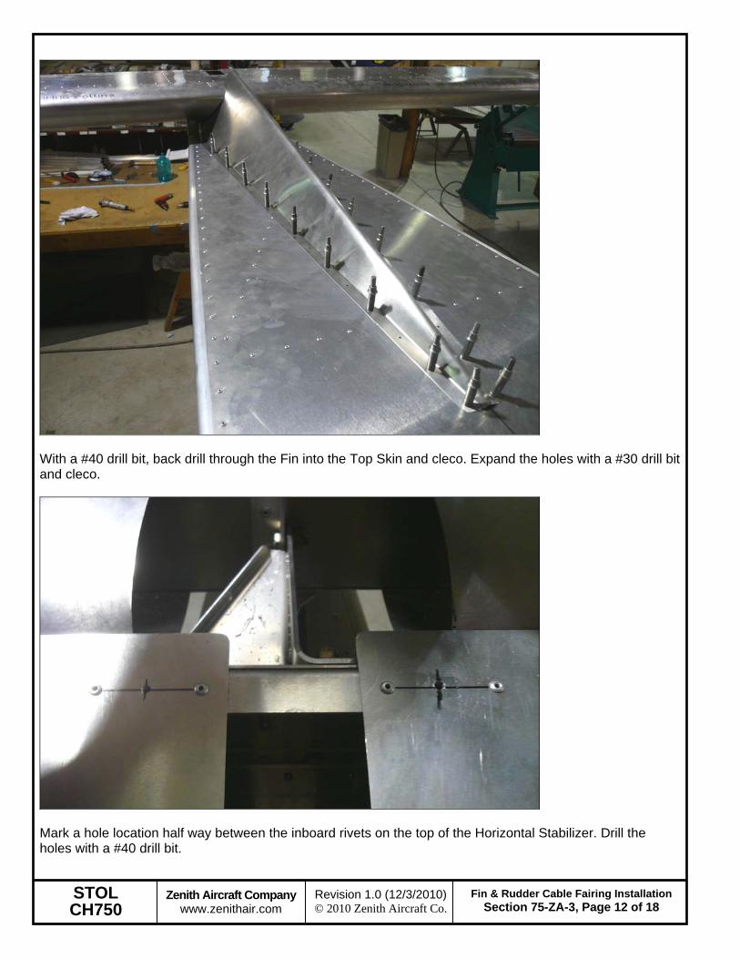
With a #40 drill bit, back drill through the Fin into the Top Skin and cleco. Expand the holes with a #30 drill bit and cleco.
Mark a hole location half way between the inboard rivets on the top of the Horizontal Stabilizer. Drill the holes with a #40 drill bit.
STOL CH750
Zenith Aircraft Company www.zenithair.com
Fin & Rudder Cable Fairing InstallationSection 75-ZA-3, Page 13 of 18
Revision 1.0 (12/3/2010) © 2010 Zenith Aircraft Co.
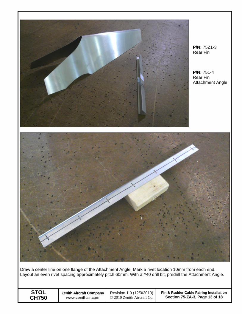
P/N: 75Z1-3 Rear Fin P/N: 751-4 Rear Fin Attachment Angle
Draw a center line on one flange of the Attachment Angle. Mark a rivet location 10mm from each end. Layout an even rivet spacing approximately pitch 60mm. With a #40 drill bit, predrill the Attachment Angle.
STOL CH750
Zenith Aircraft Company www.zenithair.com
Fin & Rudder Cable Fairing InstallationSection 75-ZA-3, Page 14 of 18
Revision 1.0 (12/3/2010) © 2010 Zenith Aircraft Co.
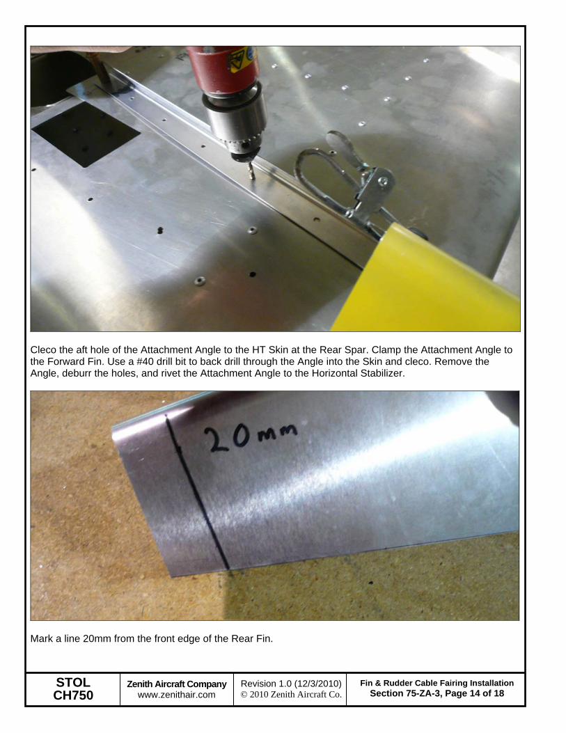
Cleco the aft hole of the Attachment Angle to the HT Skin at the Rear Spar. Clamp the Attachment Angle to the Forward Fin. Use a #40 drill bit to back drill through the Angle into the Skin and cleco. Remove the Angle, deburr the holes, and rivet the Attachment Angle to the Horizontal Stabilizer.
Mark a line 20mm from the front edge of the Rear Fin.
STOL CH750
Zenith Aircraft Company www.zenithair.com
Fin & Rudder Cable Fairing InstallationSection 75-ZA-3, Page 15 of 18
Revision 1.0 (12/3/2010) © 2010 Zenith Aircraft Co.
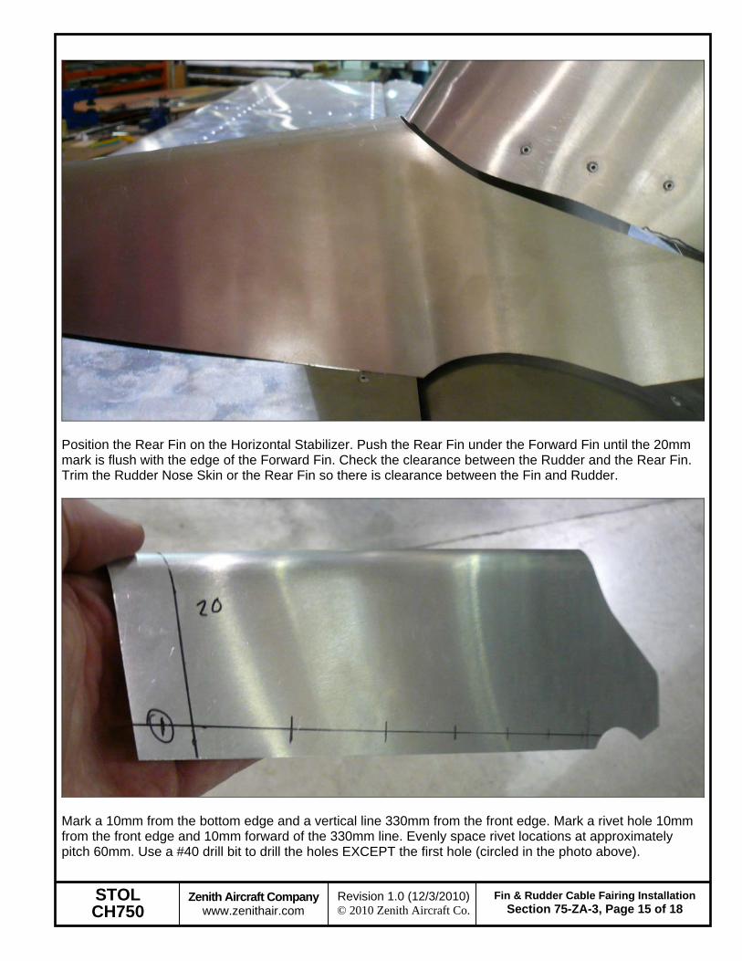
Position the Rear Fin on the Horizontal Stabilizer. Push the Rear Fin under the Forward Fin until the 20mm mark is flush with the edge of the Forward Fin. Check the clearance between the Rudder and the Rear Fin. Trim the Rudder Nose Skin or the Rear Fin so there is clearance between the Fin and Rudder.
Mark a 10mm from the bottom edge and a vertical line 330mm from the front edge. Mark a rivet hole 10mm from the front edge and 10mm forward of the 330mm line. Evenly space rivet locations at approximately pitch 60mm. Use a #40 drill bit to drill the holes EXCEPT the first hole (circled in the photo above).
STOL CH750
Zenith Aircraft Company www.zenithair.com
Fin & Rudder Cable Fairing InstallationSection 75-ZA-3, Page 16 of 18
Revision 1.0 (12/3/2010) © 2010 Zenith Aircraft Co.
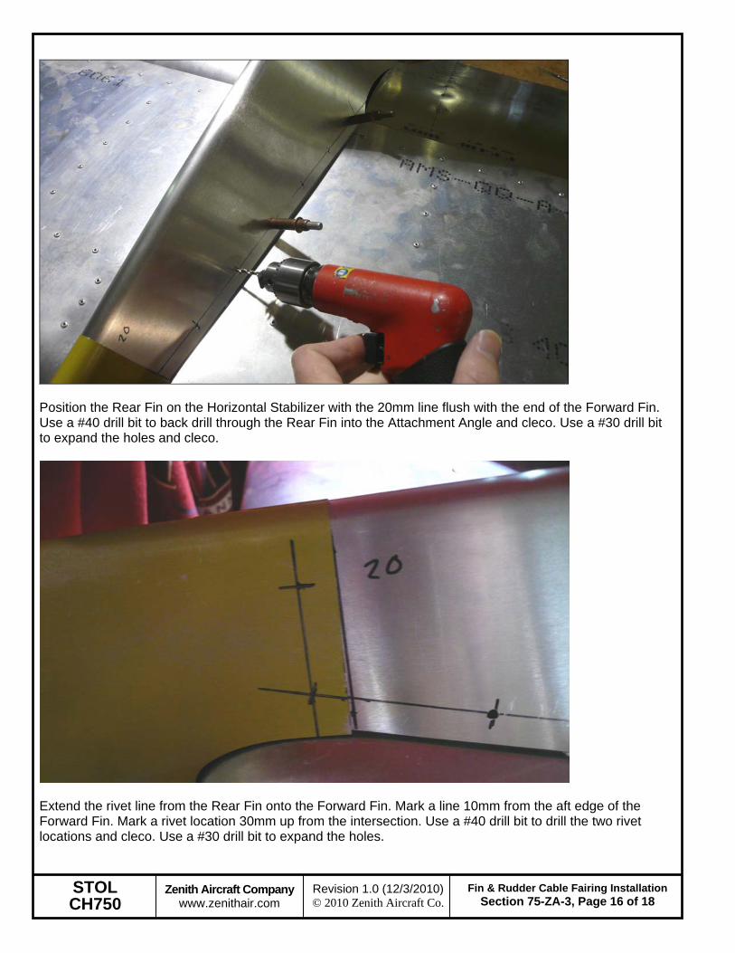
Position the Rear Fin on the Horizontal Stabilizer with the 20mm line flush with the end of the Forward Fin. Use a #40 drill bit to back drill through the Rear Fin into the Attachment Angle and cleco. Use a #30 drill bit to expand the holes and cleco.
Extend the rivet line from the Rear Fin onto the Forward Fin. Mark a line 10mm from the aft edge of the Forward Fin. Mark a rivet location 30mm up from the intersection. Use a #40 drill bit to drill the two rivet locations and cleco. Use a #30 drill bit to expand the holes.
STOL CH750
Zenith Aircraft Company www.zenithair.com
Fin & Rudder Cable Fairing InstallationSection 75-ZA-3, Page 17 of 18
Revision 1.0 (12/3/2010) © 2010 Zenith Aircraft Co.
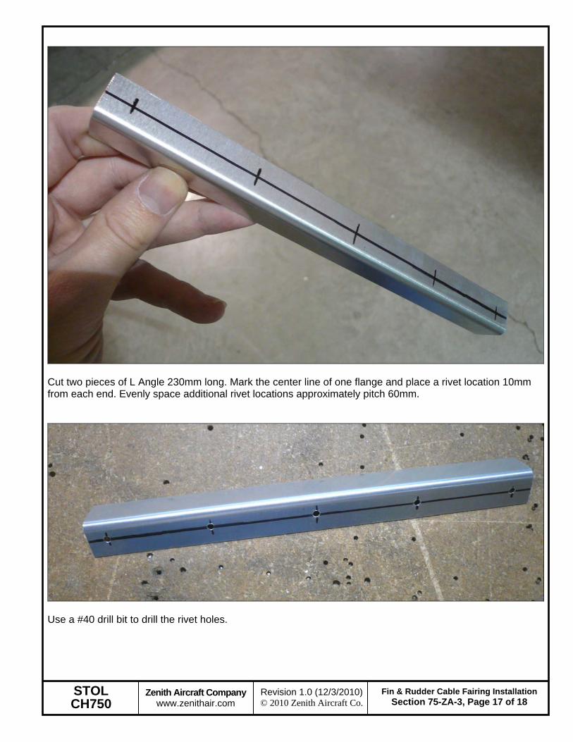
Cut two pieces of L Angle 230mm long. Mark the center line of one flange and place a rivet location 10mm from each end. Evenly space additional rivet locations approximately pitch 60mm.
Use a #40 drill bit to drill the rivet holes.
STOL CH750
Zenith Aircraft Company www.zenithair.com
Fin & Rudder Cable Fairing InstallationSection 75-ZA-3, Page 18 of 18
Revision 1.0 (12/3/2010) © 2010 Zenith Aircraft Co.
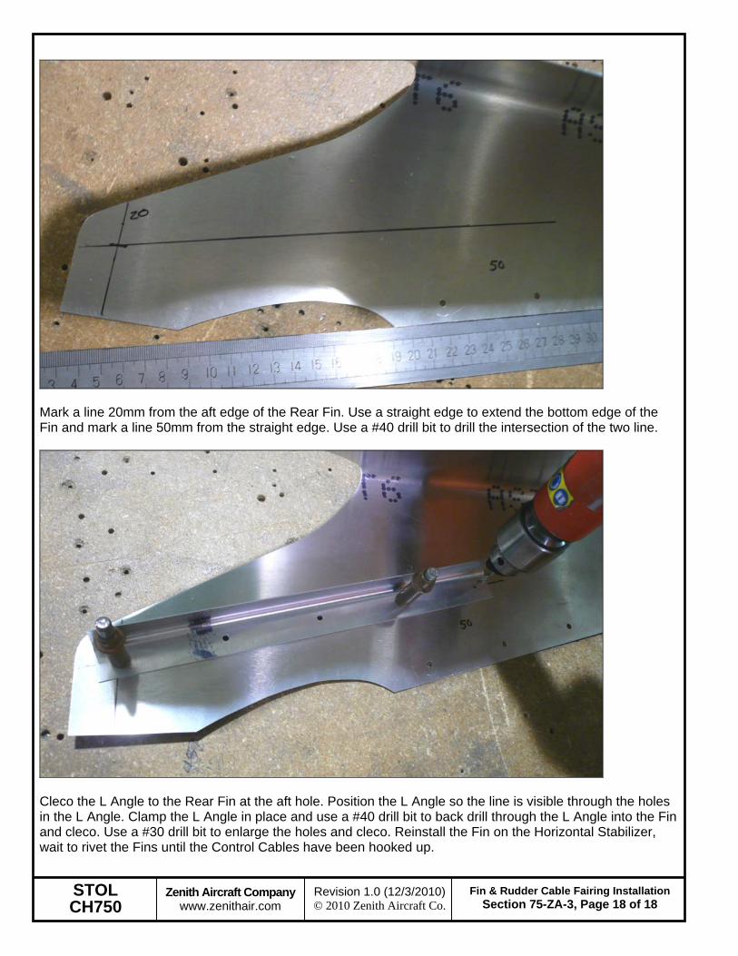
Mark a line 20mm from the aft edge of the Rear Fin. Use a straight edge to extend the bottom edge of the Fin and mark a line 50mm from the straight edge. Use a #40 drill bit to drill the intersection of the two line.
Cleco the L Angle to the Rear Fin at the aft hole. Position the L Angle so the line is visible through the holes in the L Angle. Clamp the L Angle in place and use a #40 drill bit to back drill through the L Angle into the Fin and cleco. Use a #30 drill bit to enlarge the holes and cleco. Reinstall the Fin on the Horizontal Stabilizer, wait to rivet the Fins until the Control Cables have been hooked up.