Embed Size (px)
Citation preview
Handbook
Prevention of dropped objects
Working Together for Safety (SfS): Recommended Practice 024E/2018 – Part 1
REVISION 4
2018
Prevention of dropped objects | Revision 4 3
2 Chapter 1
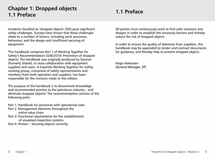
All parties must continuously work to find safer solutions and designs in order to establish the necessary barriers and thereby reduce the risk of dropped objects.
In order to ensure the quality of deliveries from suppliers, this handbook may be appended to tender and contract documents for guidance, and thereby help to prevent dropped objects.
Hugo HalvorsenGeneral Manager, SfS
Chapter 1: Dropped objects1.1 Preface 1.1 Preface
Incidents classified as ‘dropped objects’ (DO) pose significant safety challenges. Surveys have shown that these challenges relate to a number of factors, including work processes, behaviour, and the design and insufficient securing of equipment.
This handbook comprises Part 1 of Working Together for Safety’s Recommendation 024E/2018: Prevention of dropped objects. The handbook was originally produced by Equinor (formerly Statoil), in close collaboration with equipment suppliers and users. A tripartite Working Together for Safety working group, comprised of safety representatives and members from both operators and suppliers, has been responsible for the revisions made to this edition.
The purpose of the handbook is to disseminate knowledge and recommended practice to the petroleum industry – and eliminate dropped objects! The recommendation consists of the following parts:
Part 1: Handbook for personnel with operational rolesPart 2: Management elements throughout the
entire value chainPart 3: Functional requirements for the establishment
of visualised inspection systemsPart 4: Posters – Securing objects correctly
Prevention of dropped objects | Revision 4 54 Chapter 1
Chapter 6 Lifting equipment
Chapter 8Electrical equipment and instruments
Chapter 7 Securing of structures
Chapter 9 Securing of other equipment
Chapter 10Terms and abbreviations
Chapter 1 Dropped objects
Chapter 2 Risk Management
Chapter 3 Prevention of dropped objects
Chapter 4 Attachment and securing
Chapter 5 Work at height
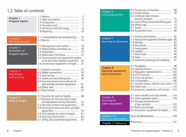
1.1 Preface ........................................... 21.2 Table of contents ............................ 41.3 Introduction.................................... 61.4 The value chain ............................. 71.5 Fall factors and fall energy............... 81.6 Reporting ....................................... 10
2.1 Understanding risk and planning .... 122.2 Barriers ........................................... 14
3.1 Management and control ............... 163.2 Responsibility and follow-up ........... 183.3 Inspections ..................................... 193.4 Observation technique .................... 223.5 Securing tools and equipment against
wind and other weather conditions . 243.6 Unnecessary equipment at height ... 25
4.1 Galvanic corrosion .......................... 274.2 Bolted connections ......................... 304.3 Lock-wiring ..................................... 384.4 Cotter pins and locking pins ............ 394.5 Securing devices and methods for
permanently installed equipment .... 414.6 Safety nets ...................................... 454.7 Wire clamps .................................... 47
5.1 Routines for work at height............. 485.2 Routines for the securing of tools
and equipment during relocation .... 525.3 Securing of tools and equipment .... 535.4 Securing of tools and other portable
equipment ...................................... 595.5 Tool cabinets for work at height ...... 615.6 Securing of personnel ..................... 646.1 Lifting and suspended equipment ... 67
1.2 Table of contents 6.2 Correct use of shackles .................... 696.3 Snatch blocks .................................. 706.4 Umbilical roller sheaves
(banana sheaves) ........................... 726.5 Loose lifting equipment/lifting gear . 746.6 Lifting lugs ...................................... 776.7 Tackle .............................................. 796.8 Suspended hose.............................. 80
7.1 Grating and hatches ....................... 827.2 Piping and equipment feedthroughs 857.3 Railings ........................................... 877.4 Toe boards ...................................... 897.5 Swing gates .................................... 907.6 Ladders ........................................... 927.7 Wind walls ...................................... 947.8 Signs .............................................. 967.9 Insulation jacketing and cladding .... 97
8.1 Floodlights ...................................... 988.2 Lighting fixtures .............................. 1008.3 Navigation lights/lanterns ................ 1028.4 CCTV cameras ................................. 1048.5 Crane equipment ............................ 1068.6 Loudspeakers .................................. 1088.7 Junction boxes, cabinets and covers 1108.8 Cable trays ...................................... 1128.9 Antennas, windsocks and sensors ... 114
9.1 Valve handles and valve wheels ...... 1169.2 Chain-operated valves .................... 1189.3 Storage and placement
of gas cylinders ............................... 1209.4 Racks and storage ........................... 1229.5 Evacuation equipment at height ..... 124
Terms & abbreviations ........................... 126
References ............................................ 131Chapter 11 References
6 Chapter 1
Prevention of dropped objects | Revision 4 7
Design Fabrikasjon Pakking Veitransport
Ved kai
Sjøtransport
Installasjon/Ferdigstillelse
Vedlikehold/reparasjon
Avvikling/demontering
Pakking
Drift
Anskaffelser
Modifikasjoner
Start her
1.4 The value chain1.3 Introduction
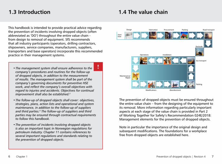
The prevention of dropped objects must be ensured throughout the entire value chain – from the designing of the equipment to its removal. More information regarding particularly important aspects at each stage of the value chain is provided in Part 2 of Working Together for Safety’s Recommendation 024E/2018: Management elements for the prevention of dropped objects.
Note in particular the importance of the original design and subsequent modifications. The foundations for a workplace free from dropped objects are established here.
This handbook is intended to provide practical advice regarding the prevention of incidents involving dropped objects (often abbreviated as ‘DO’) throughout the entire value chain - from design to removal of equipment. SfS recommends that all industry participants (operators, drilling contractors, shipowners, service companies, manufacturers, suppliers, transporters and base operators) incorporate this recommended practice in their management systems.
• The management system shall ensure adherence to the company’s procedures and routines for the follow-up of dropped objects, in addition to the measurement of results. The management system shall be part of the company’s governing documents for preventive HSE work, and reflect the company’s overall objectives with regard to injuries and accidents. Objectives for continual improvement shall also be established.3
• The follow-up of dropped objects shall cover: objectives, strategies, plans, action lists and operational and system maintenance, in addition to the follow-up of suppliers and third parties.4 The follow-up of suppliers and third parties may be ensured through contractual requirements to follow this handbook.
• The prevention of incidents involving dropped objects is also an important topic in Norwegian regulations for petroleum industry. Chapter 11 contains references to several important regulations and standards relating to the prevention of dropped objects.
Design Fabrication Procurement Packing Road transport
Dockside
Sea transport
InstallationOperations
Maintenance/Repair
Packing
Modifications Abandonment
Starthere
!
8 Chapter 1 Prevention of dropped objects | Revision 4 9
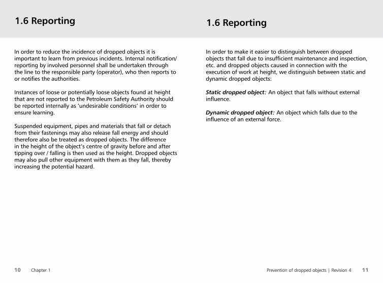
• A fall energy of over 120 joules (red zone) may result in death.13,36
• A fall energy of between 80 and 120 joules (orange zone) may result in serious injury.
• A fall energy of between 40 and 80 joules (yellow zone) may result in an injury that necessitates an absence from work.
• A fall energy of between 0 and 40 joules (green zone) may result in the need for medical treatment (20-40 Joule) or first aid/no injury.
After obtaining a preliminary classification, a full severity assessment must be performed. In addition to the fall energy, this must also take into account factors such as the object’s hardness and shape, where it hits the body, etc. Sharp objects with low kinetic energy may have a higher severity than that indicated by the preliminary classification; on the other hand, a heavy object that falls from a low height within a restricted area may have a lower severity than that indicated by the fall energy alone.
1.5 Fall factors and fall energy
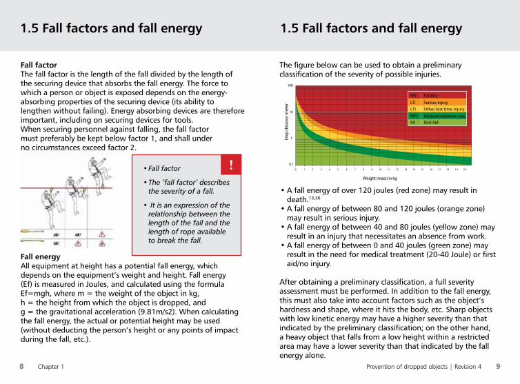
• Fall factor
• The ‘fall factor’ describes the severity of a fall.
• It is an expression of the relationship between the length of the fall and the length of rope available to break the fall.
Fall factorThe fall factor is the length of the fall divided by the length of the securing device that absorbs the fall energy. The force to which a person or object is exposed depends on the energy-absorbing properties of the securing device (its ability to lengthen without failing). Energy absorbing devices are therefore important, including on securing devices for tools.When securing personnel against falling, the fall factor must preferably be kept below factor 1, and shall under no circumstances exceed factor 2.
1.5 Fall factors and fall energy
Fall energyAll equipment at height has a potential fall energy, which depends on the equipment’s weight and height. Fall energy (Ef) is measured in Joules, and calculated using the formula Ef=mgh, where m = the weight of the object in kg, h = the height from which the object is dropped, and g = the gravitational acceleration (9.81m/s2). When calculating the fall energy, the actual or potential height may be used (without deducting the person’s height or any points of impact during the fall, etc.).
!
The figure below can be used to obtain a preliminary classification of the severity of possible injuries.
0,1
1
10
100
0 1 2 3 4 5 6 7 8 9 10 11 12 13 14 15 16 17 18 19 20
Weight (mass) in kg
Dro
p di
stan
ce i m
eter
FAT Fatality
LTI Serious injuryLTI Other lost time injury
MTC Medical treatment caseFA First Aid
Prevention of dropped objects | Revision 4 1110 Chapter 1
In order to reduce the incidence of dropped objects it is important to learn from previous incidents. Internal notification/reporting by involved personnel shall be undertaken through the line to the responsible party (operator), who then reports to or notifies the authorities.
Instances of loose or potentially loose objects found at height that are not reported to the Petroleum Safety Authority should be reported internally as ‘undesirable conditions’ in order to ensure learning.
Suspended equipment, pipes and materials that fall or detach from their fastenings may also release fall energy and should therefore also be treated as dropped objects. The difference in the height of the object’s centre of gravity before and after tipping over / falling is then used as the height. Dropped objects may also pull other equipment with them as they fall, thereby increasing the potential hazard.
1.6 Reporting
In order to make it easier to distinguish between dropped objects that fall due to insufficient maintenance and inspection, etc. and dropped objects caused in connection with the execution of work at height, we distinguish between static and dynamic dropped objects:
Static dropped object: An object that falls without external influence.
Dynamic dropped object: An object which falls due to the influence of an external force.
1.6 Reporting
12 Chapter 2 Prevention of dropped objects | Revision 4 13
2.1 Understanding risk and planning
Maintaining a good understanding of risk and risk management is a regulatory requirement4,12 and will reduce the probability of dropped objects by ensuring quality in the planning and facilitation stage, job preparations and maintenance and inspection routines.
Chapter 2: Risk Management2.1 Understanding risk and planning
a. Order, cleanliness and tidiness: Establish set (inspection)routines for the tidying up and checking of all areas in collaboration with the area responsible.
b. Safe job preparations: Understand all the subtasks involved in the work and the associated hazards and challenges.
c. Before and after the work: Perform inspections of the work site before and after the work (remember that loose objects may have been in the area over an extended period of time).
d. Assess the need for extra inspections in the event of lifting operations, special weather conditions, etc.
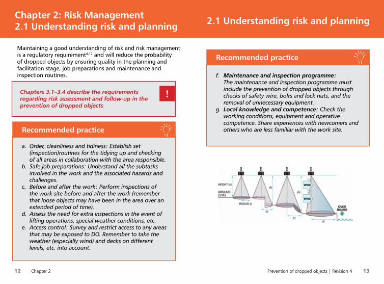
e. Access control: Survey and restrict access to any areas that may be exposed to DO. Remember to take the weather (especially wind) and decks on different levels, etc. into account.
Recommended practice
f. Maintenance and inspection programme: The maintenance and inspection programme must include the prevention of dropped objects through checks of safety wire, bolts and lock nuts, and the removal of unnecessary equipment.
g. Local knowledge and competence: Check the working conditions, equipment and operative competence. Share experiences with newcomers and others who are less familiar with the work site.
Recommended practice
Chapters 3.1–3.4 describe the requirements regarding risk assessment and follow-up in the prevention of dropped objects
!

14 Chapter 2
Prevention of dropped objects | Revision 4 15
2.2 Barriers
Human/operational solutions should not fulfil barrier functions alone; they must be combined with at least one of the other solutions. This handbook mainly describes technical and organisational barriers.
Barriers are measures intended to identify conditions that may result in faults, hazards and accident situations, prevent a specific course of events from occurring or developing, impact upon a course of events so that it takes an intended direction, or limit injuries and/or losses.5, 6 You should always be aware of the barriers protecting you, how and when they were last tested, and what might weaken them.
We have three main types of barriers: a) human/operational, b) technical and c) organisational.
2.2 Barriers
Human/operational: The actions or activities that personnel must perform in order to realise a barrier function (influenced by knowledge, experience, skills and methods).
Technical: Equipment and systems involved in the realisation of a barrier function (e.g. safety wires, cotter pins, safety valves, etc.). Often combined with organisational and/or human barriers.
Organisational: Personnel with defined roles or functions and specific competence involved in the realisation of a barrier function (e.g. procedures, specifications, checklists, etc.). Requirements regarding specific competence, training and exercises may be set for the involved personnel.
We have three main types of barriers: a) human/operational, b) technical and c) organisational.
16 Chapter 3
Prevention of dropped objects | Revision 4 17
In order to ensure the quality of deliveries from suppliers, this handbook may be appended to tender and contract documents for guidance, and thereby contribute to the prevention of dropped objects.
Management has a responsibility to
a. Ensure a high standard of orderliness and cleanliness, perform random checks and involve the area responsible.
b. Ensure that all areas have a designated area responsible.c. Ensure that a daily check of the area is performed:
• Equipment that is not in use shall be removed (or maintained).
• Equipment shall be checked for damage and wear.• Tools and equipment shall be cleaned after use and
stored correctly.• Loose lifting equipment shall be removed and stored
at an appropriate/dedicated location after use.d. Undertake weekly management inspections.e. Define and illustrate standards through the use of images
and checklists.f. Ensure that there are established routines/systems to
prevent dropped objects throughout the entire value chain.g. Facilitate and establish DO checks / control points in
maintenance and inspection programmes.h. Facilitate training in DO observation techniques (on the job
training)i. Establish a plan to control access to the work area and
secure the area against potential dropped objects. Plan the need for access and necessary tools/equipment. Coordinate simultaneous operations.
j. Establish risk assessments in plans and job planning. Establish and follow up the implementation of risk-reducing measures.
3.2 Responsibility and follow-up
In order to prevent incidents involving dropped objects, the organisation must maintain control of all personnel, tools and equipment at height, or that may fall to a lower level. It is important that the company’s management system incorporates work to prevent dropped objects that may occur during the execution of the organisation’s activities. This applies at all stages of the value chain – from the designing of equipment to its removal (see Chapter 1.4).
Chapter 3 covers conditions that must be handled by the company’s management system, and Chapter 5 contains several routines that should take the form of dedicated procedures for how the company handles various conditions. See also Working Together for Safety Recommendation 024E/2018 Part 2: Management elements for the prevention of dropped objects.
‘At height’ generally refers to objects located two or more metres above a permanent, solid deck (not above grating, scaffolding, etc.). A local assessment of the actual conditions at height should be performed.
!
Chapter 3: Prevention of DO3.1 Management and control
18 Chapter 3 Prevention of dropped objects | Revision 4 19
The identification and assessment of risk in connection with inspections and observations will reduce the possibility of dropped objects. Training in observation techniques and constant vigilance regarding possible dropped objects will result in a safer workplace.
3.3.1 Inspections
3.3 Inspections 3.2 Responsibility and follow-up
k. Establish a culture and system for learning and transfer of experience. Seek out results of inspections with regard to corrective and preventive measures – identify how recurrences can be prevented.
l. Ensure that time and resources are allocated to the implementation of these routines/systems.
You have a responsibility to
a. Follow established routines/systems for the prevention of DO, and follow up and consider your own actions in the context of any simultaneous activities.
b. Continually identify potential DO risks. Stop the operation in the event of changes and assess the need for new compensatory measures.
c. Ensure order, tidiness, cleanliness and control of all loose components during the course of the operation.
d. Check that the securing equipment for work at height is correct and in good condition.
e. Report findings or undesirable incidents.
One of management’s most important tasks is to ensure that all routines and systems are adhered to!
!
a. An annual, risk-based inspection plan shall be created. This shall specify who is responsible for the inspections and the intervals at which they shall be carried out, as well as when the plan should be updated and its current version status. The inspection of inaccessible areas may be performed using rope access.
b. Time shall be allotted to the inspection of equipment that is in continual use, or which is difficult to access due to its operation or location.
c. Nonconformities/findings should be documented using photos and text, and suggestions for corrective actions should be included. The criticality of nonconformities/findings must be assessed.
d. In addition to regular inspections, inspections shall also be carried out following major stresses to the equipment (adverse weather, jarring, collision, etc.). If possible, inspections shall also be carried out prior to significant known stresses.
Recommended practice

20 Chapter 3 Prevention of dropped objects | Revision 4 21
3.3 Inspections 3.3 Inspections
3.3.2 Periodic inspection programme using visualised inspection systems (picture books)
The expected standard shall be documented using both text and images. Equipment stored either permanently or temporarily at height and which poses a potential risk of dropped objects shall be identified and visualised with inspection points.
a. Periodic inspections focusing on dropped objects shall be carried out in accordance with the inspection programme. Such inspections are usually performed on a weekly basis.
b. Picture books containing checklists shall be prepared in accordance with Working Together for Safety’s Recommendation 024E/2018: Prevention of dropped objects – Part 3 (Functional requirements for the establishment of visualised inspection systems).
c. The periodic inspections shall be included, registered and followed up in the maintenance programme. Each picture book shall be entered in the maintenance system as a separate inspection, with all the checkpoints for each image.
d. The inspection shall cover equipment that is installed at height, but which is not in use. Equipment at height that is not in use shall be considered for removal.
Recommended practice
Remember that Part 3 of Working Together for Safety’s Recommendation 024E/2018: Prevention of dropped objects describes ‘Functional requirements for the establishment of visualised inspection systems’.
!
e. The status of the inspection plan shall be followed up and regularly reviewed at management meetings. Outstanding points/nonconformities shall be handled in accordance with the company’s internal requirements.
f. The frequency of inspections of areas and equipment, both with and without the use of rope access, shall be based on a risk assessment. The basis for this is an annual review of the entire facility. The frequency of inspections for certain parts of the facility/installation may be increased or reduced in accordance with a documented risk assessment and the subsequent conclusion and recommendation regarding the frequency of inspections.
22 Chapter 3 Prevention of dropped objects | Revision 4 23
3.4 Observation technique
Inspections should be carried out by personnel who have been trained in observation techniques. It is recommended that personnel from other departments participate in such inspection teams. It is particularly important that new/inexperienced members of staff participate in order to learn good observation techniques.
In addition to image-based inspections, periodic inspections focusing on dropped objects in all other zones/areas shall also be carried out.
Securing equipment shall be subject to regular maintenance in order to ensure that it functions as intended. Involved staff shall carry out a dropped objects risk assessment and implement the necessary measures during both planning and throughout the work process. These assessments shall be performed through inspections based on general observation technique.
3.4 Observation technique
Turn on your ‘DO radar’: Is there anything in the wrong place, any faults, or does anything look strange?
a. Set aside the necessary time for inspections at regular intervals.
b. Provide personnel with training in set inspection routines.
c. Limit the size of the area to be inspected.d. Limit the number of focus points to be inspected.e. Divide the areas and focus points between the
members of the inspection team. f. Check the area and focus points. This is best done
by a single member of the team or smaller group. Walk back and forth across the area in order to view the control points from several angles.
g. Remember to observe moving equipment, relating to planned operations, in order to identify possible collision points that can cause dynamic DO.
h. Findings that do not conform to an established standard, best practice or checklist should be photographed and an accurate description and site reference provided. Identified nonconformities must be corrected to ensure safe conditions.
i. Follow-up and the correction of findings are decisive factors in preventing dropped objects.
Recommended practice
!
24 Chapter 3 Prevention of dropped objects | Revision 4 25
3.6 Unnecessary equipment
at height3.5 Securing tools and equipment against
wind and other weather conditions
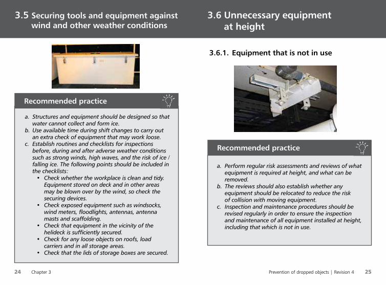
a. Structures and equipment should be designed so that water cannot collect and form ice.
b. Use available time during shift changes to carry out an extra check of equipment that may work loose.
c. Establish routines and checklists for inspections before, during and after adverse weather conditions such as strong winds, high waves, and the risk of ice / falling ice. The following points should be included in the checklists:
• Check whether the workplace is clean and tidy. Equipment stored on deck and in other areas may be blown over by the wind, so check the securing devices.
• Check exposed equipment such as windsocks, wind meters, floodlights, antennas, antenna masts and scaffolding.
• Check that equipment in the vicinity of the helideck is sufficiently secured.
• Check for any loose objects on roofs, load carriers and in all storage areas.
• Check that the lids of storage boxes are secured.
Recommended practice
a. Perform regular risk assessments and reviews of what equipment is required at height, and what can be removed.
b. The reviews should also establish whether any equipment should be relocated to reduce the risk of collision with moving equipment.
c. Inspection and maintenance procedures should be revised regularly in order to ensure the inspection and maintenance of all equipment installed at height, including that which is not in use.
Recommended practice
3.6.1. Equipment that is not in use
Prevention of dropped objects | Revision 4 27
26 Chapter 3
When installing equipment at height it is important to use the correct attachment methods. These must be weatherproof and not give grounds for galvanic corrosion.
Galvanic corrosion occurs when two dissimilar metals with different voltage potentials come into contact with each other in the presence of an electrolyte (damp film or seawater / fresh water). When this happens, the less noble metal becomes the anode and corrodes, and the more noble metal becomes the cathode.
In addition to the difference in voltage potential, the surface area of the exposed surface is an important factor for galvanic corrosion. A large anode surface area in relation to the cathode results in a significant reduction in galvanic corrosion, since the galvanic currents are distributed across a large area. This means that an acid-proof stainless steel screw installed in a large, thick aluminium sheet (of seawater resistant quality) will result in little galvanic corrosion, and therefore provide a good connection. On the other hand, an aluminium screw in a large sheet of stainless steel will corrode relatively quickly in a damp environment.
Chapter 4: Attachment and securing4.1 Galvanic corrosion
3.6 Unnecessary equipment at height
a. Perform DO inspections after all construction work, modifications, audit stoppages, etc.
b. Consider implementing ‘hazard hunts’ and similar campaigns to clear tools and equipment at height.
Recommended practice
The area responsible has a particular responsibility to ensure the area remains clean and tidy.
!
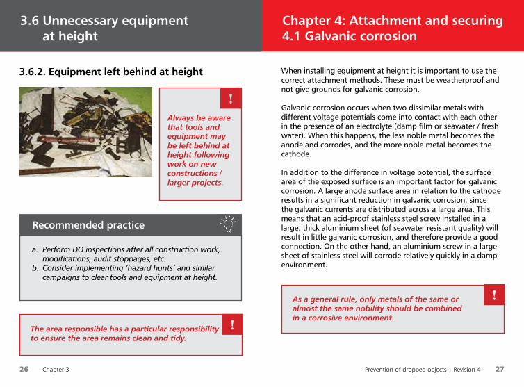
Always be aware that tools and equipment may be left behind at height following work on new constructions / larger projects.
!
As a general rule, only metals of the same or almost the same nobility should be combined in a corrosive environment.
!
3.6.2. Equipment left behind at height
28 Chapter 4 Prevention of dropped objects | Revision 4 29
4.1 Galvanic corrosion4.1 Galvanic corrosion
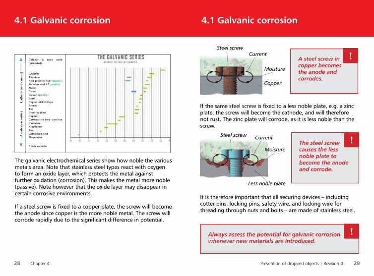
The galvanic electrochemical series show how noble the various metals area. Note that stainless steel types react with oxygen to form an oxide layer, which protects the metal against further oxidation (corrosion). This makes the metal more noble (passive). Note however that the oxide layer may disappear in certain corrosive environments.
If a steel screw is fixed to a copper plate, the screw will become the anode since copper is the more noble metal. The screw will corrode rapidly due to the significant difference in potential.
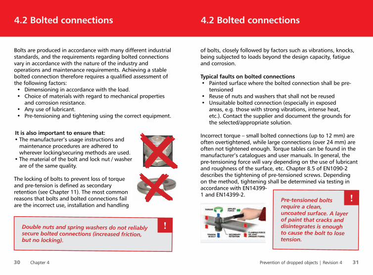
A steel screw in copper becomes the anode and corrodes.
!
The steel screw causes the less noble plate to become the anode and corrode.
!
Always assess the potential for galvanic corrosion whenever new materials are introduced.
!
If the same steel screw is fixed to a less noble plate, e.g. a zinc plate, the screw will become the cathode, and will therefore not rust. The zinc plate will corrode, as it is less noble than the screw.
It is therefore important that all securing devices – including cotter pins, locking pins, safety wire, and locking wire for threading through nuts and bolts – are made of stainless steel.
Steel screwCurrent
Copper
Moisture
Steel screw Current
Less noble plate
Moisture
27
Cathode is more noble (protected)
Graphite Titanium Acid-proof steel A4 (passive)Stainless steel A2 (passive)Monel Nickel Inconel (passive)Lead Copper-nickel alloys Bronze Tin Lead-tin alloys Copper Carbon steel, iron / cast iron Cadmium Aluminium Zinc Galvanised steel Magnesium
Anode corrodes
The galvanic electrochemical series show how noble the various metals area. Note that stainless steel types react with oxygen to form an oxide layer, which protects the metal against further oxidation (corrosion). This makes the metal more noble (passive). Note however that the oxide layer may disappear in certain corrosive environments.
If a steel screw is fixed to a copper plate, the screw will become the anode since copper is the more noble metal. The screw will corrode rapidly due to the significant difference in potential.
Ano
de (l
ess n
oble
)
C
atho
de (m
ore
nobl
e)
30 Chapter 4 Prevention of dropped objects | Revision 4 31
4.2 Bolted connections
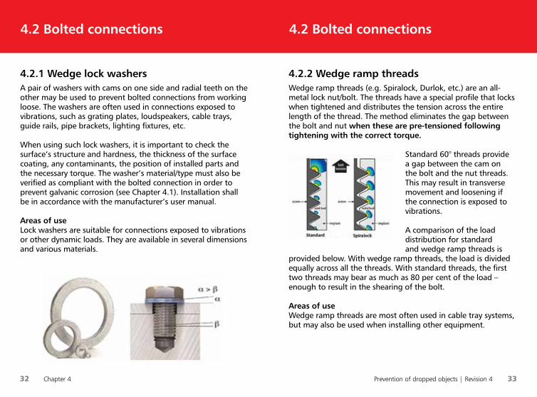
of bolts, closely followed by factors such as vibrations, knocks, being subjected to loads beyond the design capacity, fatigue and corrosion.
Typical faults on bolted connections• Painted surface where the bolted connection shall be pre-
tensioned• Reuse of nuts and washers that shall not be reused• Unsuitable bolted connection (especially in exposed
areas, e.g. those with strong vibrations, intense heat, etc.). Contact the supplier and document the grounds for the selected/appropriate solution.
Incorrect torque – small bolted connections (up to 12 mm) are often overtightened, while large connections (over 24 mm) are often not tightened enough. Torque tables can be found in the manufacturer’s catalogues and user manuals. In general, the pre-tensioning force will vary depending on the use of lubricant and roughness of the surface, etc. Chapter 8.5 of EN1090-2 describes the tightening of pre-tensioned screws. Depending on the method, tightening shall be determined via testing in accordance with EN14399-1 and EN14399-2.
Bolts are produced in accordance with many different industrial standards, and the requirements regarding bolted connections vary in accordance with the nature of the industry and operations and maintenance requirements. Achieving a stable bolted connection therefore requires a qualified assessment of the following factors:• Dimensioning in accordance with the load.• Choice of materials with regard to mechanical properties
and corrosion resistance.• Any use of lubricant.• Pre-tensioning and tightening using the correct equipment.
It is also important to ensure that:• The manufacturer’s usage instructions and
maintenance procedures are adhered to wherever locking/securing methods are used.
• The material of the bolt and lock nut / washer are of the same quality.
The locking of bolts to prevent loss of torque and pre-tension is defined as secondary retention (see Chapter 11). The most common reasons that bolts and bolted connections fail are the incorrect use, installation and handling
4.2 Bolted connections
Pre-tensioned bolts require a clean, uncoated surface. A layer of paint that cracks and disintegrates is enough to cause the bolt to lose tension.
!
Double nuts and spring washers do not reliably secure bolted connections (increased friction, but no locking).
!
32 Chapter 4 Prevention of dropped objects | Revision 4 33
4.2.2 Wedge ramp threads Wedge ramp threads (e.g. Spiralock, Durlok, etc.) are an all-metal lock nut/bolt. The threads have a special profile that locks when tightened and distributes the tension across the entire length of the thread. The method eliminates the gap between the bolt and nut when these are pre-tensioned following tightening with the correct torque.
Standard 60° threads provide a gap between the cam on the bolt and the nut threads. This may result in transverse movement and loosening if the connection is exposed to vibrations.
A comparison of the load distribution for standard and wedge ramp threads is
provided below. With wedge ramp threads, the load is divided equally across all the threads. With standard threads, the first two threads may bear as much as 80 per cent of the load – enough to result in the shearing of the bolt.
Areas of useWedge ramp threads are most often used in cable tray systems, but may also be used when installing other equipment.
4.2 Bolted connections
4.2.1 Wedge lock washers A pair of washers with cams on one side and radial teeth on the other may be used to prevent bolted connections from working loose. The washers are often used in connections exposed to vibrations, such as grating plates, loudspeakers, cable trays, guide rails, pipe brackets, lighting fixtures, etc.
When using such lock washers, it is important to check the surface’s structure and hardness, the thickness of the surface coating, any contaminants, the position of installed parts and the necessary torque. The washer’s material/type must also be verified as compliant with the bolted connection in order to prevent galvanic corrosion (see Chapter 4.1). Installation shall be in accordance with the manufacturer’s user manual.
Areas of useLock washers are suitable for connections exposed to vibrations or other dynamic loads. They are available in several dimensions and various materials.
4.2 Bolted connections
34 Chapter 4 Prevention of dropped objects | Revision 4 35
4.2 Bolted connections4.2 Bolted connections
Areas of useNylon lock nuts are usually used in stainless connections of dimension M10 or lower, where there is little or no vibration and within a temperature range of -70°C to +120°C.
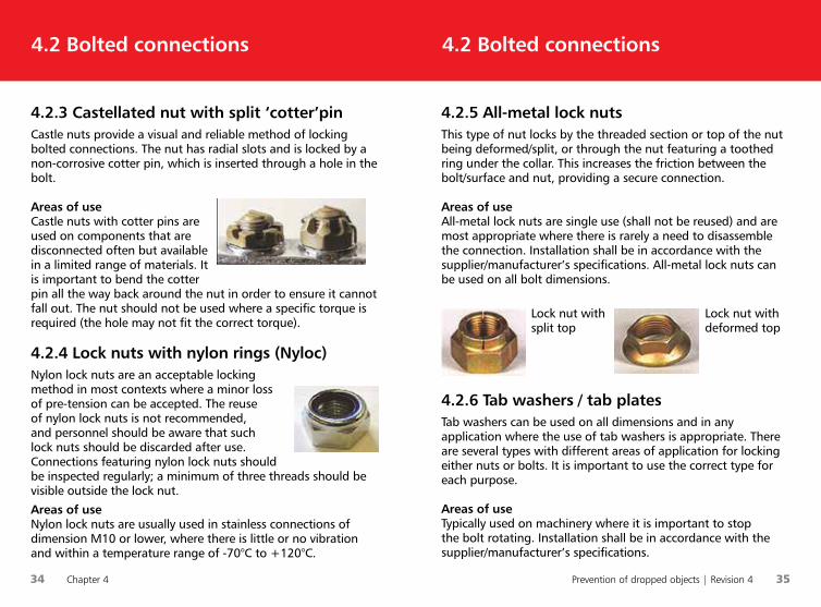
4.2.3 Castellated nut with split ‘cotter’pinCastle nuts provide a visual and reliable method of locking bolted connections. The nut has radial slots and is locked by a non-corrosive cotter pin, which is inserted through a hole in the bolt.
Areas of useCastle nuts with cotter pins are used on components that are disconnected often but available in a limited range of materials. It is important to bend the cotter pin all the way back around the nut in order to ensure it cannot fall out. The nut should not be used where a specific torque is required (the hole may not fit the correct torque).
4.2.4 Lock nuts with nylon rings (Nyloc) Nylon lock nuts are an acceptable locking method in most contexts where a minor loss of pre-tension can be accepted. The reuse of nylon lock nuts is not recommended, and personnel should be aware that such lock nuts should be discarded after use. Connections featuring nylon lock nuts should be inspected regularly; a minimum of three threads should be visible outside the lock nut.
4.2.5 All-metal lock nuts This type of nut locks by the threaded section or top of the nut being deformed/split, or through the nut featuring a toothed ring under the collar. This increases the friction between the bolt/surface and nut, providing a secure connection.
Areas of useAll-metal lock nuts are single use (shall not be reused) and are most appropriate where there is rarely a need to disassemble the connection. Installation shall be in accordance with the supplier/manufacturer’s specifications. All-metal lock nuts can be used on all bolt dimensions.
Lock nut with split top
Lock nut with deformed top
4.2.6 Tab washers / tab plates Tab washers can be used on all dimensions and in any application where the use of tab washers is appropriate. There are several types with different areas of application for locking either nuts or bolts. It is important to use the correct type for each purpose.
Areas of useTypically used on machinery where it is important to stop the bolt rotating. Installation shall be in accordance with the supplier/manufacturer’s specifications.
36 Chapter 4 Prevention of dropped objects | Revision 4 37
4.3 Lock-wiring 4.2 Bolted connections
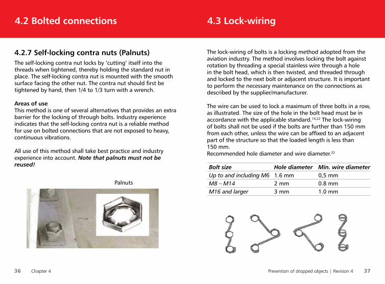
The lock-wiring of bolts is a locking method adopted from the aviation industry. The method involves locking the bolt against rotation by threading a special stainless wire through a hole in the bolt head, which is then twisted, and threaded through and locked to the next bolt or adjacent structure. It is important to perform the necessary maintenance on the connections as described by the supplier/manufacturer.
The wire can be used to lock a maximum of three bolts in a row, as illustrated. The size of the hole in the bolt head must be in accordance with the applicable standard.14,22 The lock-wiring of bolts shall not be used if the bolts are further than 150 mm from each other, unless the wire can be affixed to an adjacent part of the structure so that the loaded length is less than 150 mm.Recommended hole diameter and wire diameter.22
Bolt size Hole diameter Min. wire diameter Up to and including M6 1.6 mm 0,5 mm M8 – M14 2 mm 0.8 mm M16 and larger 3 mm 1.0 mm
4.2.7 Self-locking contra nuts (Palnuts)The self-locking contra nut locks by ‘cutting’ itself into the threads when tightened, thereby holding the standard nut in place. The self-locking contra nut is mounted with the smooth surface facing the other nut. The contra nut should first be tightened by hand, then 1/4 to 1/3 turn with a wrench.
Areas of useThis method is one of several alternatives that provides an extra barrier for the locking of through bolts. Industry experience indicates that the self-locking contra nut is a reliable method for use on bolted connections that are not exposed to heavy, continuous vibrations.
All use of this method shall take best practice and industry experience into account. Note that palnuts must not be reused!
Palnuts

38 Chapter 4 Prevention of dropped objects | Revision 4 39
4.4 Cotter pins and locking pins
Cotter pins are used to secure bolts and nuts and must be adapted to the size of the relevant bolt and nut.22, 24 Cotter pins will weaken with reuse, and single use is therefore recommended
Areas of useCotter pins and locking pins are used with scaffolding bolts, insulation cladding, safety bolts on removable railings, claw couplings and securing brackets on gas cylinder racks, etc.
4.3 Lock-wiring
Split ‘cotter’ pin
!
Areas of useThe lock-wiring of bolts is used extensively in locking external bolted connections on drilling and pipe-handling equipment. The method is often used where there are no through-bolts and/or it is necessary to be able to easily check the locking visually.
Lock-wiring of bolts shall be carried out by personnel with sufficient training.
Cotter pins and locking pins hould be stainless steel and of the correct dimension and quality.
40 Chapter 4 Prevention of dropped objects | Revision 4 41
Wherever possible, equipment installed at height shall feature integrated secondary retention. If this is not possible, or if there is a risk of the equipment being dropped, the equipment shall feature extra retention in the form of wire rope/net/chain or similar, attached to the structure.
The manufacturer shall provide a user manual that describes how the device shall be installed, and how the barriers shall be inspected and maintained. Securing devices shall be installed in accordance with such instructions, and in a manner that ensures the length of the fall is as short as possible.
The securing device shall tolerate the maximum load that may occur if the usual attachment method fails. The maximum load shall be documented. All equipment shall be secured based on factors including movement, vibration, load during use, temperature, corrosion, and wind/weather conditions (e.g. seafastening).
The equipment shall be designed so that inspections and maintenance can be easily carried out without a risk of the equipment being dropped. The system used to secure the equipment must tolerate the maximum load to which the equipment may be subjected.
In order to ensure continual improvement, a system for the transfer of experience between the owner/user and manufacturer should be established. Such a system will ensure that necessary information and experience regarding any equipment faults will be communicated to other users within a reasonable timeframe.
4.5 Securing devices and methods forpermanently installed equipment4.4 Cotter pins and locking pins
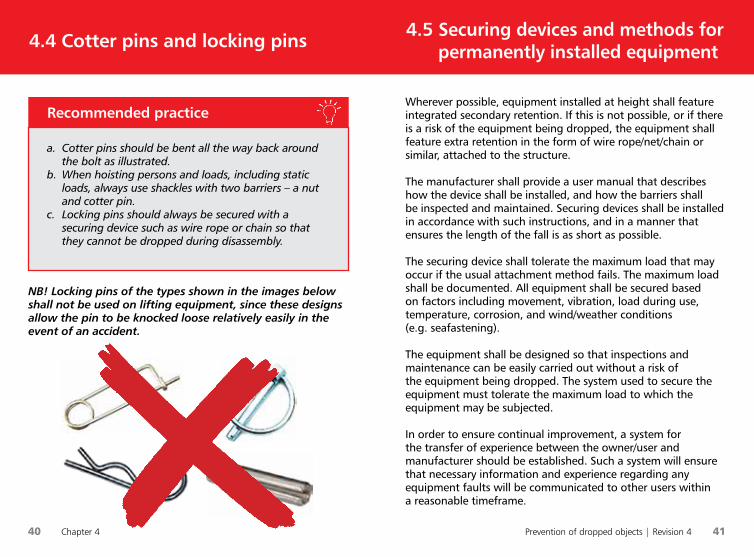
NB! Locking pins of the types shown in the images below shall not be used on lifting equipment, since these designs allow the pin to be knocked loose relatively easily in the event of an accident.
a. Cotter pins should be bent all the way back around the bolt as illustrated.
b. When hoisting persons and loads, including static loads, always use shackles with two barriers – a nut and cotter pin.
c. Locking pins should always be secured with a securing device such as wire rope or chain so that they cannot be dropped during disassembly.
Recommended practice

42 Chapter 4 Prevention of dropped objects | Revision 4 43
4.5 Securing devices and methods for
permanently installed equipment
All securing devices and attachment points on equipment shall be documented. Traceability information shall also be available, including a minimum of batch or ID labelling, manufacturer/importer, year and information about the maximum load (weight of the tool and maximum drop height). In addition, information about the material type, product standard and a user manual must be made available.
4.5 Securing devices and methods forpermanently installed equipment
• I løfteoperasjoner skal det IKKE benyttes traktorsplinter, sikkerhetsnåler eller hårnålsplinter.
• Splittpinner skal bøyes så mye at de ikke kan slås ut.
Sikker bruk av sjakler i løfteoperasjoner
Verktøy på bildene er kun ment som illustrasjon. Andre verktøy/sikring enheter kan være tilgjengelige i markedet.
a. Securing devices shall be dimensioned to withstand the forces that may occur if equipment falls down. Securing devices shall not be used for lifting.
b. Chains shall be made of acid-proof or hot-dip galvanized steel.
c. Stainless or acid-proof wire rope, e.g. 7x19, 6x7 – AISI 316, shall be used as safety wire.
d. Safety wires shall be manufactured with a soft eye and ferrules at each end, in accordance with the standard.16
e. Connectors linked to safety wires should be stainless alloy.
f. C-link (quick link) or shackles are the recommended connectors for the securing of permanently installed equipment.
g. Shackles for use with securing devices should have a nut and cotter pin.
h. The length of the securing device shall be as short as possible in order to minimise the potential fall energy.
i. Visual inspections of securing devices should be performed before installation.
j. Securing devices that have been exposed to a drop must be discarded.29
k. Securing devices shall be installed, maintained and inspected in line with the information given
Recommended practice
44 Chapter 4 Prevention of dropped objects | Revision 4 45
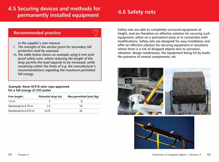
Safety nets are able to completely surround equipment at height, and are therefore an effective solution for securing such equipment, either on a permanent basis or in connection with modifications. Safety nets are designed for easy installation and offer an effective solution for securing equipment in situations where there is a risk of dropped objects due to corrosion, vibration, design weaknesses, the equipment being hit by loads, the presence of several components, etc.
4.6 Safety nets 4.5 Securing devices and methods forpermanently installed equipment
in the supplier’s user manual.l. The strength of the anchor point for secondary fall
protection shall be assessed. m. The table below shows an example using 6 mm acid-
proof safety wire, where reducing the length of the drop permits the load capacity to be increased, while remaining within the limits of e.g. the manufacturer’s recommendations regarding the maximum permitted fall energy.
Recommended practice
Example: 6mm SF316 wire rope approved for a fall energy of 235 joules
Free length: Potential drop (m) Max.permitted load (kg)
1,5 m 3 8
Shortened to 0.75 m 1,5 16
Shortened to 0.375 m 0,75 32
46 Chapter 4 Prevention of dropped objects | Revision 4 47
4.7 Wire clamps4.6 Safety nets
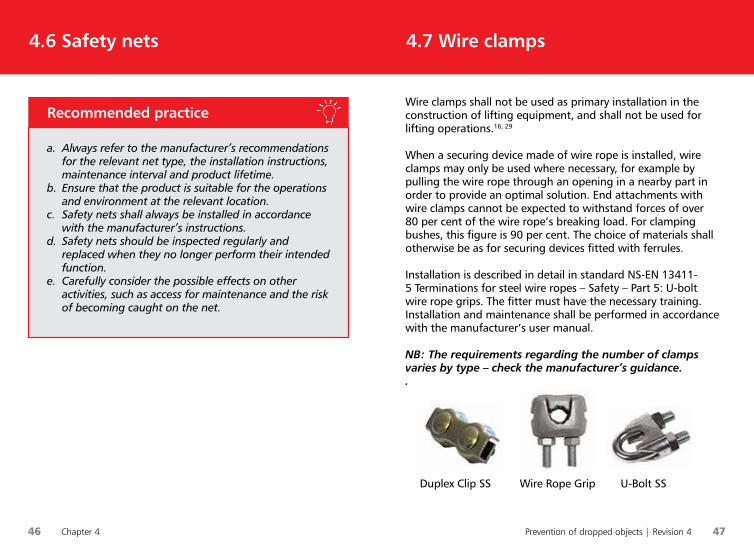
Wire clamps shall not be used as primary installation in the construction of lifting equipment, and shall not be used for lifting operations.16, 29
When a securing device made of wire rope is installed, wire clamps may only be used where necessary, for example by pulling the wire rope through an opening in a nearby part in order to provide an optimal solution. End attachments with wire clamps cannot be expected to withstand forces of over 80 per cent of the wire rope’s breaking load. For clamping bushes, this figure is 90 per cent. The choice of materials shall otherwise be as for securing devices fitted with ferrules.
Installation is described in detail in standard NS-EN 13411-5 Terminations for steel wire ropes – Safety – Part 5: U-bolt wire rope grips. The fitter must have the necessary training. Installation and maintenance shall be performed in accordance with the manufacturer’s user manual.
NB: The requirements regarding the number of clamps varies by type – check the manufacturer’s guidance..
Duplex Clip SS Wire Rope Grip U-Bolt SS
a. Always refer to the manufacturer’s recommendations for the relevant net type, the installation instructions, maintenance interval and product lifetime.
b. Ensure that the product is suitable for the operations and environment at the relevant location.
c. Safety nets shall always be installed in accordance with the manufacturer’s instructions.
d. Safety nets should be inspected regularly and replaced when they no longer perform their intended function.
e. Carefully consider the possible effects on other activities, such as access for maintenance and the risk of becoming caught on the net.
Recommended practice
48 Chapter 5 Prevention of dropped objects | Revision 4 49
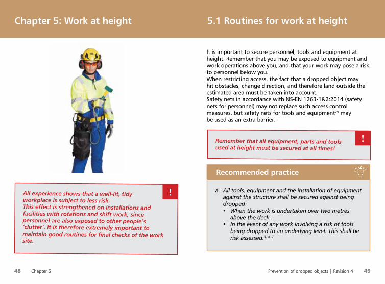
It is important to secure personnel, tools and equipment at height. Remember that you may be exposed to equipment and work operations above you, and that your work may pose a risk to personnel below you.When restricting access, the fact that a dropped object may hit obstacles, change direction, and therefore land outside the estimated area must be taken into account. Safety nets in accordance with NS-EN 1263-1&2:2014 (safety nets for personnel) may not replace such access control measures, but safety nets for tools and equipment29 may be used as an extra barrier.
5.1 Routines for work at heightChapter 5: Work at height
All experience shows that a well-lit, tidy workplace is subject to less risk.This effect is strengthened on installations and facilities with rotations and shift work, since personnel are also exposed to other people’s ‘clutter’. It is therefore extremely important to maintain good routines for final checks of the work site.
!
Remember that all equipment, parts and tools used at height must be secured at all times!
!
a. All tools, equipment and the installation of equipment against the structure shall be secured against being dropped:• When the work is undertaken over two metres
above the deck.• In the event of any work involving a risk of tools
being dropped to an underlying level. This shall be risk assessed.3, 4, 7
Recommended practice
50 Chapter 5 Prevention of dropped objects | Revision 4 51
5.1 Routines for work at height5.1 Routines for work at height
b. The risk assessment shall take into account who and what will be influenced by the work, and who must be notified before the work starts.
c. Use a helmet with a chin strap, preferably four-point.d. Appoint a tools responsible for jobs involving several
workers. The tools responsible shall ensure that tools taken up to height are brought down again.
e. Use approved checklists prior to work at height in order to check aspects including the following:• Does the job require a work permit/safe job
analysis?• Are all parts, equipment and materials that shall
be used at height secured against being dropped – including during transport?
• Has the procedure for work at height been read and understood?
• Has a sufficiently large area of the work site been cordoned off?
• Are smaller parts stored in boxes, bags or other types of closable storage? Storage solutions should also be secured against being dropped, and their contents should remain in place even if the storage solution is turned upside down.
f. Before starting the work, check the securing straps and attachment points on personal equipment, and inspect tools based on the supplier’s user manual.
Recommended practice
g. A log shall be used to register all tools used at height by both the area responsible and involved personnel. The following details should be provided when registering tools in the log:• Date and time• Tool and ID label• Signatures from both the relevant worker and area
responsibleh. All personnel who enter the derrick shall be logged,
with the date and time at which they enter and leave.i. In the event of deviations between the log and
registered tools and equipment found at height / in tool cabinets at height, immediate action shall be taken to check what is missing.
Recommended practice
The area responsible shall maintain an overview of all personnel working at height at all times.
!
52 Chapter 5 Prevention of dropped objects | Revision 4 53
5.3 Securing of tools and equipment 5.2 Routines for the securing of tools and equipment during relocation
a. All tools and equipment shall be secured against falling when being moved to and from the work site.
b. When using tool belts, tools and equipment shall be secured using the attachment point and transported on tool hooks. This must be documented by the supplier.
c. Bags, sacks and belts shall be marked with the maximum tool weight for storage during relocation. The maximum storage limit shall not be exceeded.
d. If tools and equipment weighing over 2 kg shall be transported, the use of suitable bags, sacks and belts is recommended.
e. When transporting tools and equipment with a weight of up to 5 kg, tools and equipment may be secured to attachment points approved by the supplier during transport only. Securing straps shall be made as short as possible to eliminate high potential fall energy.
Recommended practice
NB! Tools or equipment weighing over 2 kg shall not be secured to personnel during the work
!
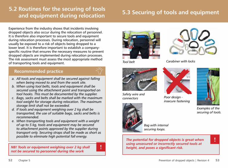
Tool belt Carabiner with locks
Examples of the securing of tools.
Safety wire and connectors
Bag with internalsecuring loops.
The potential for dropped objects is great when using unsecured or incorrectly secured tools at height, and poses a significant risk.
!
Experience from the industry shows that incidents involving dropped objects also occur during the relocation of personnel. It is therefore also important to secure tools and equipment during relocation processes. During relocation, personnel will usually be exposed to a risk of objects being dropped to a lower level. It is therefore important to establish a company-specific routine that ensures the necessary measures to prevent dropped objects are implemented during relocation processes. The risk assessment must assess the most appropriate method of transporting tools and equipment.
Poor design -insecure fastening

54 Chapter 5 Prevention of dropped objects | Revision 4 55
5.3 Securing of tools and equipment 5.3 Securing of tools and equipment
a. All tools, equipment and equipment installed against the structure shall be secured against being dropped when:• The work is undertaken over two metres above
the deck.• There is a risk of tools and equipment used at
height being dropped to the underlying level. The risk of tools and equipment used at height being dropped shall be risk assessed.
b. All tools and equipment shall be secured against being dropped, both during transport/relocation and during the work.8
c. Perform pre-use checks on securing straps and the attachment points on personal equipment and tools, based on the supplier’s recommendations.
d. Securing devices shall be dimensioned to withstand the forces that may occur if equipment falls down. The entire assembly must be of the same material quality.
e. If wire rope is used as a securing device, a corrosion resistant material (e.g. AISI 316, 7x19 IWRC) shall be used and inspected in accordance with the manufacturer’s user manual.35
f. Use securing devices, equipment and tools manufactured in accordance with the approved standard.29
Recommended practice
g. Securing straps for tools and equipment used at height supplied fitted with connectors shall feature locking devices and eyelets/eyes. These may be carabiners.
h. Straps and the like used to secure tools should be energy-absorbing (fall arrest). The total drop height must not represent a risk.
i. The length of the securing device shall be as short as possible in order to minimise the potential fall energy.
j. Securing devices that have been exposed to a drop must be discarded.29
k. Weak links shall only be used when these are an integrated part of the securing strap, and for tools weighing less than 1 kg.
l. Loose weak links / key rings shall not be used.m. The attachment points on tools, bags, backpacks or
belts shall be labelled and documented. Attachment points shall be tested and verified for the maximum arresting force. The maximum arresting force is based on the weight of the tool and the maximum drop height.
n. Bags, backpacks and belts shall be marked with the maximum tool weight for storage during transport. Tool bags or sacks with internal loops should be used when many tools, or heavy items, shall be used.
Recommended practice
56 Chapter 5 Prevention of dropped objects | Revision 4 57
5.3 Securing of tools and equipment5.3 Securing of tools and equipment
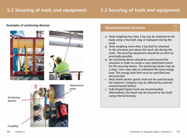
Anchoring devices
Attachment point
o. Tools weighing less than 2 kg may be attached to the body using a tool belt, bag or backpack during the work.
p. Tools weighing more than 2 kg shall be attached to the structure just above the work site during the work. The securing equipment should be as short as practically possible.
q. An anchoring device should be used around the structure in order to create a new attachment point for the securing device. The anchoring device may be a sling / wire rope able to withstand the total energy load. The energy load limit must be specified and documented.
r. Heat shrink anchor points shall not be used because the fastener’s integrity may be affected by external environmental factors.
s. Fully-forged impact tools are recommended. Alternatively, the head may be secured to the shaft using internal locking.
Recommended practice
Coupling
Examples of anchoring devices:
58 Chapter 5 Prevention of dropped objects | Revision 4 59
5.4 Securing of other
portable equipment5.3 Securing of tools and equipment
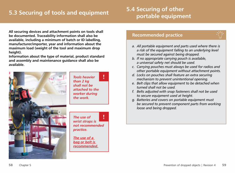
All securing devices and attachment points on tools shall be documented. Traceability information shall also be available, including a minimum of batch or ID labelling, manufacturer/importer, year and information about the maximum load (weight of the tool and maximum drop height). Information about the type of material, product standard and assembly and maintenance guidance shall also be available.
Tools heavier than 2 kg shall not be attached to the worker during the work.
!
The use of wrist straps is not recommended practice.
The use of a bag or belt is recommended.
!
a. All portable equipment and parts used where there is a risk of the equipment falling to an underlying level must be secured against being dropped.
b. If no appropriate carrying pouch is available, a universal safety net should be used.
c. Carrying pouches must always be used for radios and other portable equipment without attachment points.
d. Locks on pouches shall feature an extra securing mechanism to prevent unintentional opening.
e. Belt clips that allow equipment to be detached when turned shall not be used.
f. Belts adjusted with snap fasteners shall not be used to secure equipment used at height.
g. Batteries and covers on portable equipment must be secured to prevent component parts from working loose and being dropped.
Recommended practice
60 Chapter 5 Prevention of dropped objects | Revision 4 61
5.5 Tool cabinets for work at height5.4 Securing of other portable equipment
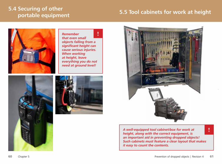
Remember that even small objects falling from a significant height can cause serious injuries.When working at height, leave everything you do not need at ground level!
!
A well-equipped tool cabinet/box for work at height, along with the correct equipment, is an important aid in preventing dropped objects! Such cabinets must feature a clear layout that makes it easy to count the contents.
!

62 Chapter 5 Prevention of dropped objects | Revision 4 63
5.5 Tool cabinets for work at height5.5 Tool cabinets for work at height
i. Securing devices for permanently installed equipment should be stored separately from tools for use at height (securing devices shall be tested as a unit – including connectors).
j. No tools or equipment should be stored in the derrick. If this is regarded as necessary following a risk assessment, boxes/cabinets should be bolted/welded to the structure and an administration routine implemented for the use and control of the equipment and tools (see b. above).
Recommended practice
a. Tool cabinets should be installed in areas where work is often undertaken at height.
b. Management and control routines should be specified in the company’s procedures.
c. Each cabinet shall have a list of contents and be kept locked. Responsibility for the cabinet shall be allocated to a member of personnel.
d. The cabinet must feature a clear layout which makes it easy to count the contents. Each hook should be marked with the tool type and quantity.
e. Users shall log all tools and equipment taken from / returned to the cabinet. As an alternative to the log, a log chip may be removed from the tool and placed in a separate box in the cabinet. The log chip should feature information about the type of tool/equipment.
f. The contents of the cabinet at height and associated logbook shall be checked by the responsible individual at the end of each shift in which the tools have been used.
g. All tools and securing equipment stored in cabinets at height shall be in accordance with Chapter 5.
h. In addition to the necessary tools, the cabinets shall be equipped with the necessary securing and anchoring devices.
Recommended practice

64 Chapter 5 Prevention of dropped objects | Revision 4 65
Documented training is a mandatory requirement for all personnel involved in work operations at height requiring the use of fall arrest equipment.32,34 Together with buddy checks and the correct use of well-maintained equipment, this provides effective securing of personnel at height.
5.6 Securing personnel 5.6 Securing personnel
a. Personnel who use fall protection equipment shall have documented training.
b. The required equipment checks before and after use shall be performed.
c. There shall always be at least one assisting person present at the work site whenever fall protection equipment is used.
d. The necessary rescue equipment and personnel must always be available at the work site. A rescue plan shall be in place.
Recommended practice
e. Everyone involved in the work must have the necessary knowledge of the equipment and its limitations, and understand the relevant emergency procedures. The manufacturer’s user manual must be followed.
f. Buddy checks shall be performed to ensure that the fall protection equipment has been correctly donned/installed.
g. Fall prevention systems are recommended.h. Be aware of the need for clearance below the person
when using lifeline systems.i. Fall protection equipment shall be labelled in
accordance with the relevant standards for personal protective equipment.35
j. The equipment shall be checked a minimum of every 12 months by a competent person. Whether the label date specifies the ‘valid to’ or ‘checked’ date must be indicated.
k. The suspension attachment point / anchor point shall have a tolerance at least equal to that recommended by the manufacturer.
l. The harness should feature two relief straps (e.g. trauma straps that the worker can stand on to relieve pressure from the legs and ensure adequate blood circulation).
m. Fall arrest blocks are only recommended for use within a restricted area. Pendulous falls can be dangerous. Most fall blocks are only intended/designed to be suspended above the work site.
Recommended practice
Remember Buddycheck !
Prevention of dropped objects | Revision 4 67
66 Chapter 5
Chapter 6: Lifting equipment6.1 Lifting and suspended equipment5.6 Securing personnel
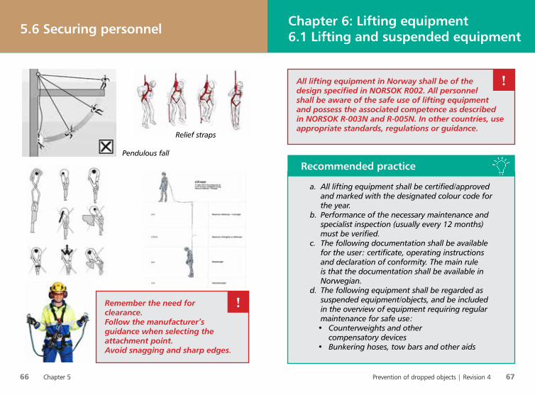
Pendulous fall
Relief straps
Remember the need for clearance.Follow the manufacturer’s guidance when selecting the attachment point.Avoid snagging and sharp edges.
!
a. All lifting equipment shall be certified/approved and marked with the designated colour code for the year.
b. Performance of the necessary maintenance and specialist inspection (usually every 12 months) must be verified.
c. The following documentation shall be available for the user: certificate, operating instructions and declaration of conformity. The main rule is that the documentation shall be available in Norwegian.
d. The following equipment shall be regarded as suspended equipment/objects, and be included in the overview of equipment requiring regular maintenance for safe use:
• Counterweights and other compensatory devices
• Bunkering hoses, tow bars and other aids
Recommended practice
All lifting equipment in Norway shall be of the design specified in NORSOK R002. All personnel shall be aware of the safe use of lifting equipment and possess the associated competence as described in NORSOK R-003N and R-005N. In other countries, use appropriate standards, regulations or guidance.
!
68 Chapter 6 Prevention of dropped objects | Revision 4 69
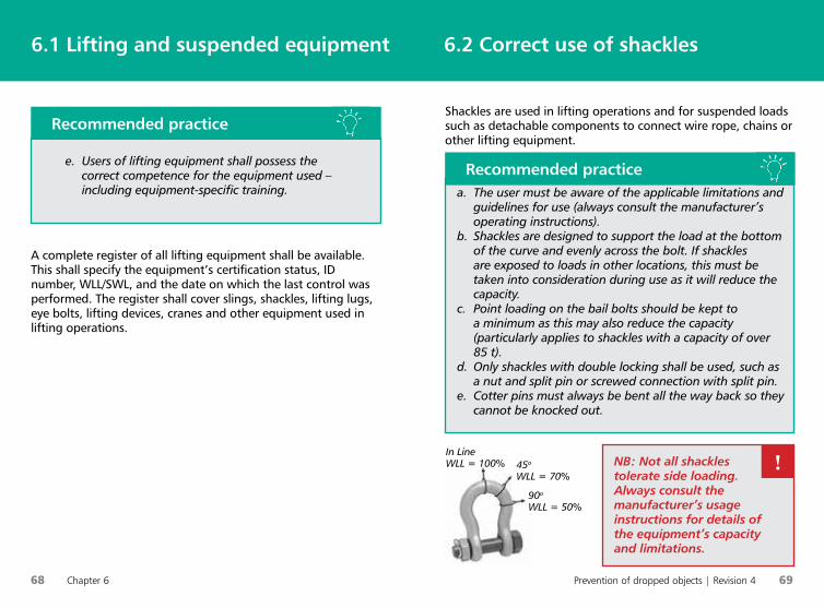
Shackles are used in lifting operations and for suspended loads such as detachable components to connect wire rope, chains or other lifting equipment.
6.2 Correct use of shackles6.1 Lifting and suspended equipment
A complete register of all lifting equipment shall be available. This shall specify the equipment’s certification status, ID number, WLL/SWL, and the date on which the last control was performed. The register shall cover slings, shackles, lifting lugs, eye bolts, lifting devices, cranes and other equipment used in lifting operations.
a. The user must be aware of the applicable limitations and guidelines for use (always consult the manufacturer’s operating instructions).
b. Shackles are designed to support the load at the bottom of the curve and evenly across the bolt. If shackles are exposed to loads in other locations, this must be taken into consideration during use as it will reduce the capacity.
c. Point loading on the bail bolts should be kept to a minimum as this may also reduce the capacity (particularly applies to shackles with a capacity of over 85 t).
d. Only shackles with double locking shall be used, such as a nut and split pin or screwed connection with split pin.
e. Cotter pins must always be bent all the way back so they cannot be knocked out.
Recommended practice
NB: Not all shackles tolerate side loading. Always consult the manufacturer’s usage instructions for details of the equipment’s capacity and limitations.
!In LineWLL = 100% 45o
WLL = 70%
90o
WLL = 50%
e. Users of lifting equipment shall possess the correct competence for the equipment used – including equipment-specific training.
Recommended practice
70 Chapter 6 Prevention of dropped objects | Revision 4 71
6.3 Snatch blocks 6.3 Snatch blocks
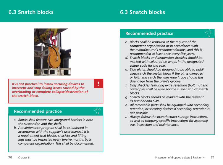
a. Blocks shall feature two integrated barriers in both the suspension and the shaft.
b. A maintenance program shall be established in accordance with the supplier’s user manual. It is a requirement that blocks, shackles and lifting lugs must be inspected every twelve months by a competent organisation. This shall be documented.
Recommended practice
It is not practical to install securing devices to intercept and stop falling items caused by the overloading or complete collapse/destruction of the snatch block.
!
c. Blocks shall be removed at the request of the competent organisation or in accordance with the manufacturer’s recommendations, and this is recommended at least once every five years.
d. Snatch blocks and suspension shackles should be marked with coloured tie wraps in the designated colour code for the year.
e. Side plates should be designed to be able to hold/clasp/catch the snatch block if the pin is damaged or fails, and catch the wire rope / rope should this disengage from the plate’s groove.
f. Only shackles featuring extra retention (bolt, nut and cotter pin) shall be used for the suspension of snatch blocks.
g. Snatch blocks should be marked with the relevant ID number and SWL.
h. All removable parts shall be equipped with secondary retention, or securing devices if secondary retention is not possible.
i. Always follow the manufacturer’s usage instructions, as well as company-specific instructions for assembly, use, inspection and maintenance.
Recommended practice
72 Chapter 6 Prevention of dropped objects | Revision 4 73
6.4 Umbilical roller sheaves
(banana sheaves ) 6.4 Umbilical roller sheaves
(banana sheaves )
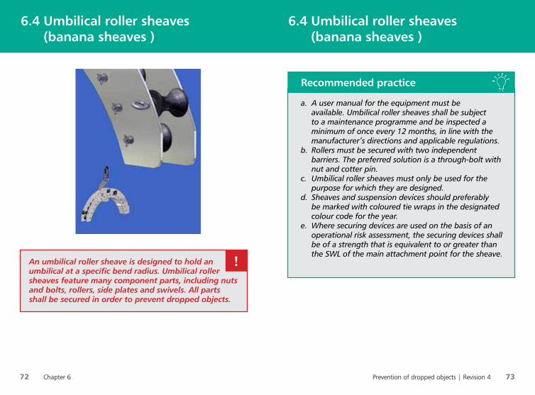
An umbilical roller sheave is designed to hold an umbilical at a specific bend radius. Umbilical roller sheaves feature many component parts, including nuts and bolts, rollers, side plates and swivels. All parts shall be secured in order to prevent dropped objects.
!
a. A user manual for the equipment must be available. Umbilical roller sheaves shall be subject to a maintenance programme and be inspected a minimum of once every 12 months, in line with the manufacturer’s directions and applicable regulations.
b. Rollers must be secured with two independent barriers. The preferred solution is a through-bolt with nut and cotter pin.
c. Umbilical roller sheaves must only be used for the purpose for which they are designed.
d. Sheaves and suspension devices should preferably be marked with coloured tie wraps in the designated colour code for the year.
e. Where securing devices are used on the basis of an operational risk assessment, the securing devices shall be of a strength that is equivalent to or greater than the SWL of the main attachment point for the sheave.
Recommended practice
74 Chapter 6 Prevention of dropped objects | Revision 4 75
6.5 Loose lifting equipment /
lifting gear
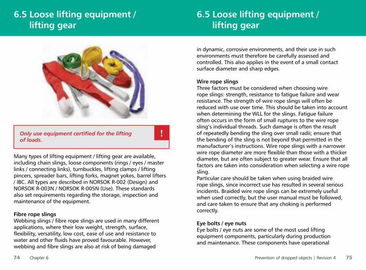
in dynamic, corrosive environments, and their use in such environments must therefore be carefully assessed and controlled. This also applies in the event of a small contact surface diameter and sharp edges. Wire rope slingsThree factors must be considered when choosing wire rope slings: strength, resistance to fatigue failure and wear resistance. The strength of wire rope slings will often be reduced with use over time. This should be taken into account when determining the WLL for the slings. Fatigue failure often occurs in the form of small ruptures to the wire rope sling’s individual threads. Such damage is often the result of repeatedly bending the sling over small radii; ensure that the bending of the sling is not beyond that permitted in the manufacturer’s instructions. Wire rope slings with a narrower wire rope diameter are more flexible than those with a thicker diameter, but are often subject to greater wear. Ensure that all factors are taken into consideration when selecting a wire rope sling.Particular care should be taken when using braided wire rope slings, since incorrect use has resulted in several serious incidents. Braided wire rope slings can be extremely useful when used correctly, but the user manual must be followed, and care taken to ensure that any choking is performed correctly.
Eye bolts / eye nutsEye bolts / eye nuts are some of the most used lifting equipment components, particularly during production and maintenance. These components have operational
Many types of lifting equipment / lifting gear are available, including chain slings, loose components (rings / eyes / master links / connecting links), turnbuckles, lifting clamps / lifting pincers, spreader bars, lifting forks, magnet yokes, barrel lifters / IBC. All types are described in NORSOK R-002 (Design) and NORSOK R-003N / NORSOK R-005N (Use). These standards also set requirements regarding the storage, inspection and maintenance of the equipment.
Fibre rope slingsWebbing slings / fibre rope slings are used in many different applications, where their low weight, strength, surface, flexibility, versatility, low cost, ease of use and resistance to water and other fluids have proved favourable. However, webbing and fibre slings are also at risk of being damaged
6.5 Loose lifting equipment / lifting gear
Only use equipment certified for the lifting of loads.
!
76 Chapter 6 Prevention of dropped objects | Revision 4 77
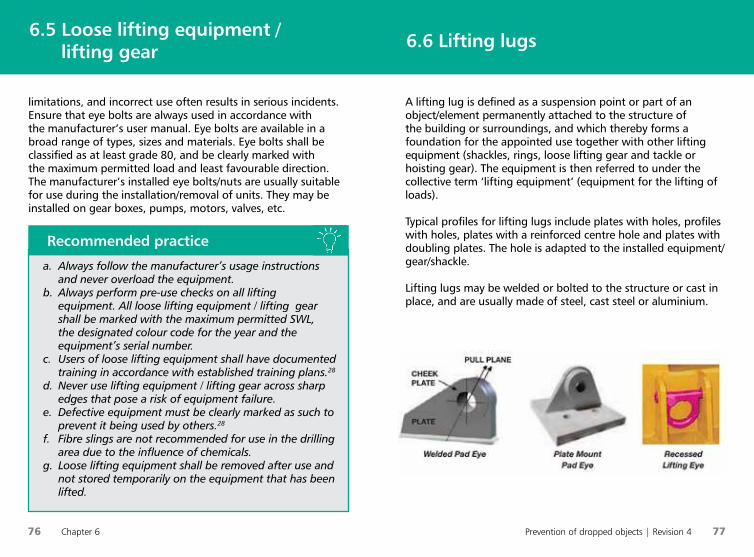
A lifting lug is defined as a suspension point or part of an object/element permanently attached to the structure of the building or surroundings, and which thereby forms a foundation for the appointed use together with other lifting equipment (shackles, rings, loose lifting gear and tackle or hoisting gear). The equipment is then referred to under the collective term ‘lifting equipment’ (equipment for the lifting of loads).
Typical profiles for lifting lugs include plates with holes, profiles with holes, plates with a reinforced centre hole and plates with doubling plates. The hole is adapted to the installed equipment/gear/shackle.
Lifting lugs may be welded or bolted to the structure or cast in place, and are usually made of steel, cast steel or aluminium.
6.6 Lifting lugs6.5 Loose lifting equipment / lifting gear
a. Always follow the manufacturer’s usage instructions and never overload the equipment.
b. Always perform pre-use checks on all lifting equipment. All loose lifting equipment / lifting gear shall be marked with the maximum permitted SWL, the designated colour code for the year and the equipment’s serial number.
c. Users of loose lifting equipment shall have documented training in accordance with established training plans.28
d. Never use lifting equipment / lifting gear across sharp edges that pose a risk of equipment failure.
e. Defective equipment must be clearly marked as such to prevent it being used by others.28
f. Fibre slings are not recommended for use in the drilling area due to the influence of chemicals.
g. Loose lifting equipment shall be removed after use and not stored temporarily on the equipment that has been lifted.
Recommended practice
limitations, and incorrect use often results in serious incidents. Ensure that eye bolts are always used in accordance with the manufacturer’s user manual. Eye bolts are available in a broad range of types, sizes and materials. Eye bolts shall be classified as at least grade 80, and be clearly marked with the maximum permitted load and least favourable direction. The manufacturer’s installed eye bolts/nuts are usually suitable for use during the installation/removal of units. They may be installed on gear boxes, pumps, motors, valves, etc.
78 Chapter 6 Prevention of dropped objects | Revision 4 79
There are several different types of block and tackle used for the lifting of loads, including chain blocks, wire rope blocks (Tirfor) and pullers. All have properties that make them user-friendly in different environments/applications.
The various types of tackle shall only be used for the lifting of loads by competent personnel.
6.7 Tackle6.6 Lifting lugs
a. Always follow the manufacturer’s instructions for the use of lifting lugs.
b. Lifting lugs that have not been produced in accordance with the relevant design standards should be immediately taken out of use and/or discarded.15
c. The relevant ID/tag number and SWL shall be specified in the immediate vicinity of lifting lugs permanently installed at height, and should be visible/readable from the normal working position for the equipment connected to the lifting lug.
d. Lifting lugs should be installed in a manner which avoids side loading.
e. Lateral movement beyond the plane is limited, and determined by the calculations and design.
f. Only shackles of the correct size in relation to the lifting lug’s design shall be used.
g. The inspection and certification of lifting lugs shall be carried out in accordance with applicable regulations for the installation (including a load test and NDT if the regulations request this).
Recommended practice
a. Only use equipment certified for the lifting of loads.b. Always follow the manufacturer’s usage instructions.c. Tackle shall be marked with the maximum permitted
SWL, the designated colour code for the year and the equipment’s serial number.
d. Always perform pre-use checks of all lifting equipment.
e. Users of loose lifting equipment shall have documented training in accordance with established training plans.28
f. Never use lifting equipment / lifting gear across sharp edges that pose a risk of equipment failure.
g. Never overload the equipment.h. Defective equipment must be clearly marked as such
to prevent it being used by others.
Recommended practice
80 Chapter 6 Prevention of dropped objects | Revision 4 81
6.8 Suspended hoses6.8 Suspended hoses
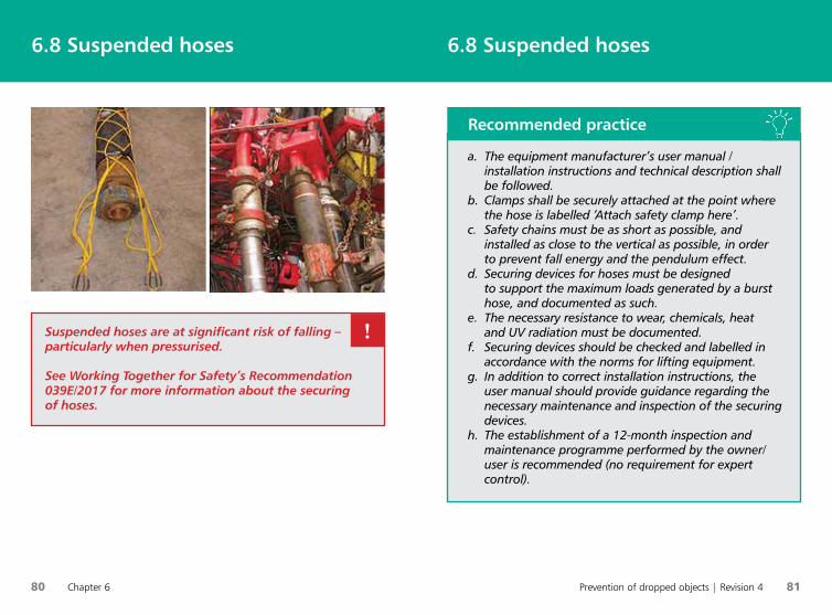
Suspended hoses are at significant risk of falling – particularly when pressurised.
See Working Together for Safety’s Recommendation 039E/2017 for more information about the securing of hoses.
!
a. The equipment manufacturer’s user manual / installation instructions and technical description shall be followed.
b. Clamps shall be securely attached at the point where the hose is labelled ‘Attach safety clamp here’.
c. Safety chains must be as short as possible, and installed as close to the vertical as possible, in order to prevent fall energy and the pendulum effect.
d. Securing devices for hoses must be designed to support the maximum loads generated by a burst hose, and documented as such.
e. The necessary resistance to wear, chemicals, heat and UV radiation must be documented.
f. Securing devices should be checked and labelled in accordance with the norms for lifting equipment.
g. In addition to correct installation instructions, the user manual should provide guidance regarding the necessary maintenance and inspection of the securing devices.
h. The establishment of a 12-month inspection and maintenance programme performed by the owner/user is recommended (no requirement for expert control).
Recommended practice
82 Chapter 7 Prevention of dropped objects | Revision 4 83
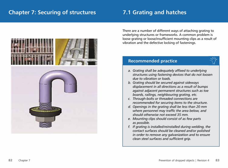
There are a number of different ways of attaching grating to underlying structures or frameworks. A common problem is loose grating or loose/insufficient mounting clips as a result of vibration and the defective locking of fastenings.
7.1 Grating and hatchesChapter 7: Securing of structures
a. Grating shall be adequately affixed to underlying structures using fastening devices that do not loosen due to vibration or loads.
b. Grating should be secured against sideways displacement in all directions as a result of bumps against adjacent permanent structures such as toe boards, railings, neighbouring grating, etc.
c. Through-bolts or threaded connections are recommended for securing items to the structure.
d. Openings in the grating shall be less than 20 mm where personnel may traffic the area below, and should otherwise not exceed 35 mm.
e. Mounting clips should consist of as few parts as possible.
f. If grating is installed/reinstalled during welding, the contact surfaces should be cleaned and/or polished in order to remove any galvanization and to ensure clean steel surfaces and sufficient grip.
Recommended practice
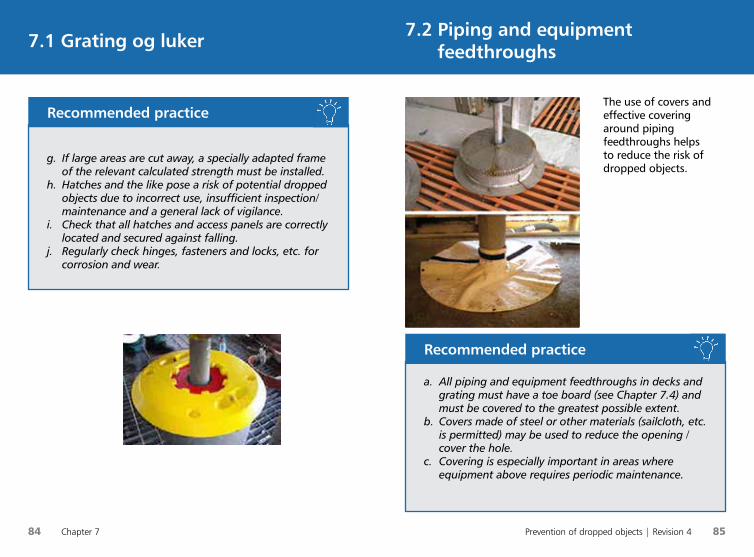
84 Chapter 7 Prevention of dropped objects | Revision 4 85
The use of covers and effective covering around piping feedthroughs helps to reduce the risk of dropped objects.
7.2 Piping and equipment feedthroughs7.1 Grating og luker
g. If large areas are cut away, a specially adapted frame of the relevant calculated strength must be installed.
h. Hatches and the like pose a risk of potential dropped objects due to incorrect use, insufficient inspection/maintenance and a general lack of vigilance.
i. Check that all hatches and access panels are correctly located and secured against falling.
j. Regularly check hinges, fasteners and locks, etc. for corrosion and wear.
Recommended practice
a. All piping and equipment feedthroughs in decks and grating must have a toe board (see Chapter 7.4) and must be covered to the greatest possible extent.
b. Covers made of steel or other materials (sailcloth, etc. is permitted) may be used to reduce the opening / cover the hole.
c. Covering is especially important in areas where equipment above requires periodic maintenance.
Recommended practice
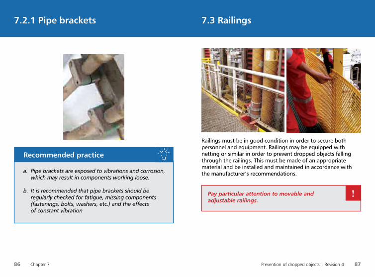
86 Chapter 7 Prevention of dropped objects | Revision 4 87
Railings must be in good condition in order to secure both personnel and equipment. Railings may be equipped with netting or similar in order to prevent dropped objects falling through the railings. This must be made of an appropriate material and be installed and maintained in accordance with the manufacturer’s recommendations.
7.3 Railings7.2.1 Pipe brackets
Pay particular attention to movable and adjustable railings.
!
a. Pipe brackets are exposed to vibrations and corrosion, which may result in components working loose.
b. It is recommended that pipe brackets should be regularly checked for fatigue, missing components (fastenings, bolts, washers, etc.) and the effects of constant vibration
Recommended practice
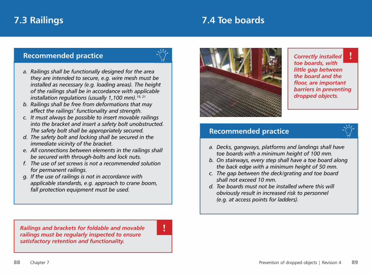
88 Chapter 7 Prevention of dropped objects | Revision 4 89
7.4 Toe boards7.3 Railings
a. Railings shall be functionally designed for the area they are intended to secure, e.g. wire mesh must be installed as necessary (e.g. loading areas). The height of the railings shall be in accordance with applicable installation regulations (usually 1,100 mm).19, 21
b. Railings shall be free from deformations that may affect the railings’ functionality and strength.
c. It must always be possible to insert movable railings into the bracket and insert a safety bolt unobstructed. The safety bolt shall be appropriately secured.
d. The safety bolt and locking shall be secured in the immediate vicinity of the bracket.
e. All connections between elements in the railings shall be secured with through-bolts and lock nuts.
f. The use of set screws is not a recommended solution for permanent railings.
g. If the use of railings is not in accordance with applicable standards, e.g. approach to crane boom, fall protection equipment must be used.
Recommended practice
Railings and brackets for foldable and movable railings must be regularly inspected to ensure satisfactory retention and functionality.
!
a. Decks, gangways, platforms and landings shall have toe boards with a minimum height of 100 mm.
b. On stairways, every step shall have a toe board along the back edge with a minimum height of 50 mm.
c. The gap between the deck/grating and toe board shall not exceed 10 mm.
d. Toe boards must not be installed where this will obviously result in increased risk to personnel (e.g. at access points for ladders).
Recommended practice
Correctly installed toe boards, with little gap between the board and the floor, are important barriers in preventing dropped objects.
!
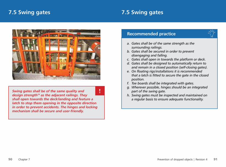
90 Chapter 7 Prevention of dropped objects | Revision 4 91
7.5 Swing gates7.5 Swing gates
Swing gates shall be of the same quality and design strength24 as the adjacent railings. They shall open towards the deck/landing and feature a latch to stop them opening in the opposite direction in order to prevent accidents. The hinges and locking mechanism shall be secure and user-friendly.
!
a. Gates shall be of the same strength as the surrounding railings.
b. Gates shall be secured in order to prevent disengaging and falling.
c. Gates shall open in towards the platform or deck.d. Gates shall be designed to automatically return to
and remain in a closed position (self-closing gates).e. On floating rigs/installations it is recommended
that a latch is fitted to secure the gate in the closed position.
f. Toe boards shall be integrated with gates.g. Wherever possible, hinges should be an integrated
part of the swing gate.h. Swing gates must be inspected and maintained on
a regular basis to ensure adequate functionality.
Recommended practice
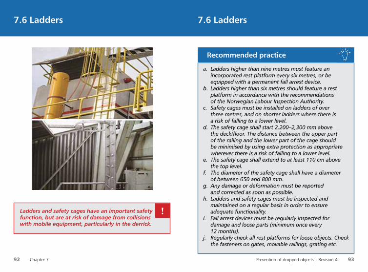
92 Chapter 7 Prevention of dropped objects | Revision 4 93
7.6 Ladders7.6 Ladders
Ladders and safety cages have an important safety function, but are at risk of damage from collisions with mobile equipment, particularly in the derrick.
!
a. Ladders higher than nine metres must feature an incorporated rest platform every six metres, or be equipped with a permanent fall arrest device.
b. Ladders higher than six metres should feature a rest platform in accordance with the recommendations of the Norwegian Labour Inspection Authority.
c. Safety cages must be installed on ladders of over three metres, and on shorter ladders where there is a risk of falling to a lower level.
d. The safety cage shall start 2,200–2,300 mm above the deck/floor. The distance between the upper part of the railing and the lower part of the cage should be minimised by using extra protection as appropriate wherever there is a risk of falling to a lower level.
e. The safety cage shall extend to at least 110 cm above the top level.
f. The diameter of the safety cage shall have a diameter of between 650 and 800 mm.
g. Any damage or deformation must be reported and corrected as soon as possible.
h. Ladders and safety cages must be inspected and maintained on a regular basis in order to ensure adequate functionality.
i. Fall arrest devices must be regularly inspected for damage and loose parts (minimum once every 12 months).
j. Regularly check all rest platforms for loose objects. Check the fasteners on gates, movable railings, grating etc.
Recommended practice
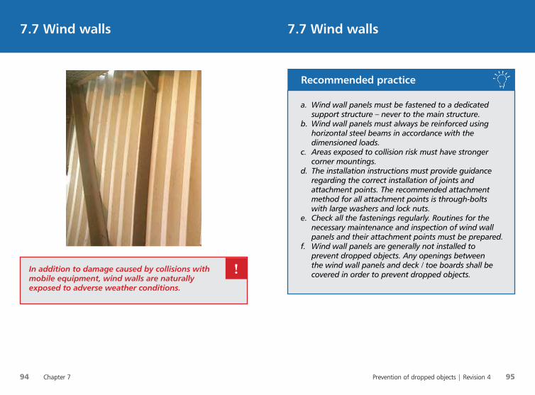
94 Chapter 7 Prevention of dropped objects | Revision 4 95
7.7 Wind walls7.7 Wind walls
In addition to damage caused by collisions with mobile equipment, wind walls are naturally exposed to adverse weather conditions.
!
a. Wind wall panels must be fastened to a dedicated support structure – never to the main structure.
b. Wind wall panels must always be reinforced using horizontal steel beams in accordance with the dimensioned loads.
c. Areas exposed to collision risk must have stronger corner mountings.
d. The installation instructions must provide guidance regarding the correct installation of joints and attachment points. The recommended attachment method for all attachment points is through-bolts with large washers and lock nuts.
e. Check all the fastenings regularly. Routines for the necessary maintenance and inspection of wind wall panels and their attachment points must be prepared.
f. Wind wall panels are generally not installed to prevent dropped objects. Any openings between the wind wall panels and deck / toe boards shall be covered in order to prevent dropped objects.
Recommended practice
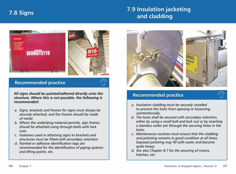
96 Chapter 7 Prevention of dropped objects | Revision 4 97
7.9 Insulation jacketing
and cladding7.8 Signs
All signs should be painted/adhered directly onto the structure. Where this is not possible, the following is recommended:
a. Signs, brackets and frames for signs must always be securely attached, and the frames should be made of metal.
b. Where the underlying material permits, sign frames should be attached using through-bolts with lock nuts.
c. Fasteners used in attaching signs to brackets and structures must be fitted with secondary retention.
d. Painted or adhesive identification tags are recommended for the identification of piping systems and lifting points, etc.
Recommended practice
a. Insulation cladding must be securely installed to prevent the locks from opening or loosening unintentionally.
b. The locks shall be secured with secondary retention, either by using a small bolt and lock nut or by inserting a stainless cotter pin through the securing holes in the locks.
c. Maintenance routines must ensure that the cladding and jacketing remains in good condition at all times. Exposed jacketing may fill with water and become quite heavy.
d. See also Chapter 8.7 for the securing of covers, hatches, etc.
Recommended practice

98 Chapter 8 Prevention of dropped objects | Revision 4 99
8.1 FloodlightsChapter 8: Electrical equipment and instruments
a. Floodlights should be positioned where they will not be hit by moving equipment/loads.
b. If there is a risk that the floodlights may be hit by moving equipment/loads, they must be protected with reinforced cages/rejectors or nets as extra barriers. Securing of the cages/rejectors must also be considered.
c. Bolts used to attach the floodlight and any associated transformer to the bracket and structure shall be equipped with secondary retention, see Chapter 4.2 Bolted connections.
Recommended practice
d. Floodlights without integrated secondary retention should be equipped with extra retention. The attachment points for wire rope or chains should be integrated, for example with eye bolts threaded into the floodlight housing. NB:• Remember that EX requirements may not permit
puncturing of the floodlight housing.• Remember to lock eye bolts in order to
prevent them from working loose in the event of vibrations.
e. Hatches/screens for the replacement of light bulbs must be hinged or secured to the floodlight housing/frame using wire rope.
f. The strength of the attachment points and securing devices in relation to the dynamic fall energy shall be documented (see table in Chapter 4.5).
g. For new installations, or when installing securing devices on existing equipment, an up-to-date user manual and maintenance instructions shall be made available and followed.
Recommended practice
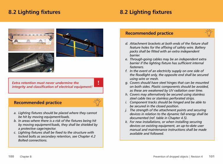
100 Chapter 8 Prevention of dropped objects | Revision 4 101
8.2 Lighting fixtures8.2 Lighting fixtures
a. Lighting fixtures should be placed where they cannot be hit by moving equipment/loads.
b. In areas where there is a risk of the fixtures being hit by moving equipment/loads, they shall be shielded by a protective cage/rejector.
c. Lighting fixtures shall be fixed to the structure with locked bolts as secondary retention, see Chapter 4.2 Bolted connections.
Recommended practice
Extra retention must never undermine the integrity and classification of electrical equipment!
!
d. Attachment brackets at both ends of the fixture shall feature holes for the affixing of safety wire. Battery packs shall be fitted with an extra independent barrier.
e. Through-going cables may be an independent extra barrier if the lighting fixture has sufficient internal fasteners.
f. In the event of an electricity supply on one side of the floodlight only, the opposite end shall be secured using wire or mesh.
g. Covers should have steel hinges that can be mounted on both sides. Plastic components should be avoided, as these are weakened by UV radiation over time.
h. Covers may alternatively be secured using stainless steel cable ties or stainless perforated strips.
i. Component tracks should be hinged and be able to be secured in the closed position.
j. The strength of the attachment points and securing devices in relation to the dynamic fall energy shall be documented (ref. table in Chapter 4.5).
k. For new installations, or when installing securing devices on existing equipment, an up-to-date user manual and maintenance instructions shall be made available and followed.
Recommended practice
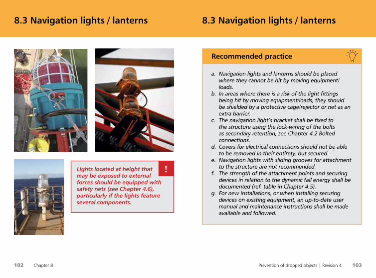
102 Chapter 8 Prevention of dropped objects | Revision 4 103
8.3 Navigation lights / lanterns8.3 Navigation lights / lanterns
Lights located at height that may be exposed to external forces should be equipped with safety nets (see Chapter 4.6), particularly if the lights feature several components.
!
a. Navigation lights and lanterns should be placed where they cannot be hit by moving equipment/loads.
b. In areas where there is a risk of the light fittings being hit by moving equipment/loads, they should be shielded by a protective cage/rejector or net as an extra barrier.
c. The navigation light’s bracket shall be fixed to the structure using the lock-wiring of the bolts as secondary retention, see Chapter 4.2 Bolted connections.
d. Covers for electrical connections should not be able to be removed in their entirety, but secured.
e. Navigation lights with sliding grooves for attachment to the structure are not recommended.
f. The strength of the attachment points and securing devices in relation to the dynamic fall energy shall be documented (ref. table in Chapter 4.5).
g. For new installations, or when installing securing devices on existing equipment, an up-to-date user manual and maintenance instructions shall be made available and followed.
Recommended practice
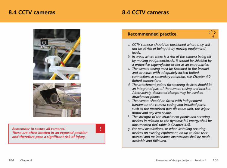
104 Chapter 8 Prevention of dropped objects | Revision 4 105
8.4 CCTV cameras8.4 CCTV cameras
Remember to secure all cameras! These are often located in an exposed position and therefore pose a significant risk of injury.
!
a. CCTV cameras should be positioned where they will not be at risk of being hit by moving equipment/loads.
b. In areas where there is a risk of the camera being hit by moving equipment/loads, it should be shielded by a protective cage/rejector or net as an extra barrier.
c. The camera casing must be fastened to the bracket and structure with adequately locked bolted connections as secondary retention, see Chapter 4.2 Bolted connections.
d. The attachment points for securing devices should be an integrated part of the camera casing and bracket. Alternatively, dedicated clamps may be used as attachment points.
e. The camera should be fitted with independent barriers on the camera casing and installed parts, such as the motorised pan-tilt-zoom unit, the wiper motor and any lens shade.
f. The strength of the attachment points and securing devices in relation to the dynamic fall energy shall be documented (ref. table in Chapter 4.5).
g. For new installations, or when installing securing devices on existing equipment, an up-to-date user manual and maintenance instructions shall be made available and followed.
Recommended practice
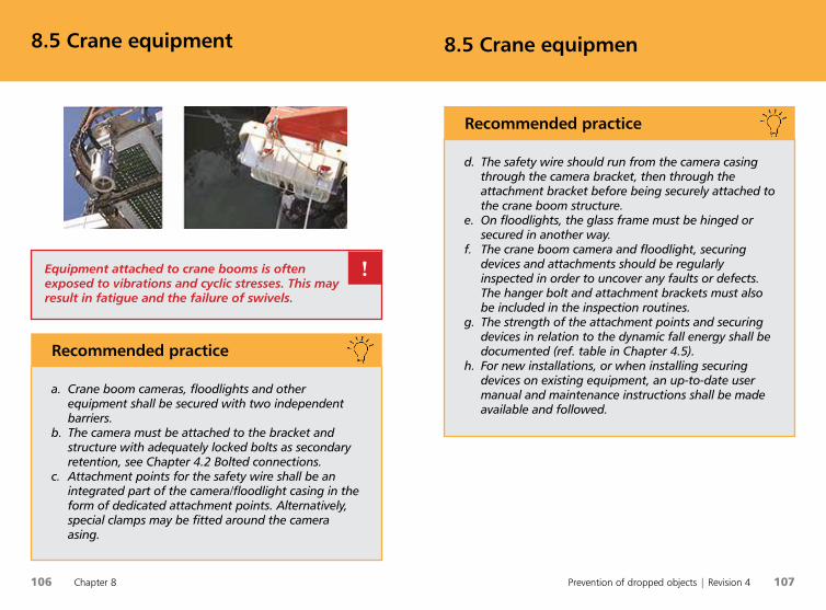
106 Chapter 8 Prevention of dropped objects | Revision 4 107
8.5 Crane equipmen8.5 Crane equipment
Equipment attached to crane booms is often exposed to vibrations and cyclic stresses. This may result in fatigue and the failure of swivels.
!
a. Crane boom cameras, floodlights and other equipment shall be secured with two independent barriers.
b. The camera must be attached to the bracket and structure with adequately locked bolts as secondary retention, see Chapter 4.2 Bolted connections.
c. Attachment points for the safety wire shall be an integrated part of the camera/floodlight casing in the form of dedicated attachment points. Alternatively, special clamps may be fitted around the camera asing.
Recommended practice
d. The safety wire should run from the camera casing through the camera bracket, then through the attachment bracket before being securely attached to the crane boom structure.
e. On floodlights, the glass frame must be hinged or secured in another way.
f. The crane boom camera and floodlight, securing devices and attachments should be regularly inspected in order to uncover any faults or defects. The hanger bolt and attachment brackets must also be included in the inspection routines.
g. The strength of the attachment points and securing devices in relation to the dynamic fall energy shall be documented (ref. table in Chapter 4.5).
h. For new installations, or when installing securing devices on existing equipment, an up-to-date user manual and maintenance instructions shall be made available and followed.
Recommended practice

108 Chapter 8 Prevention of dropped objects | Revision 4 109
8.6 Loudspeakers8.6 Loudspeakers
Loudspeakers are often located at height and therefore generally occupy an exposed position. Check all fastenings and retention regularly!
!
a. Loudspeakers should be positioned where they cannot be hit by moving equipment.
b. Loudspeakers must be attached to fixtures in a way that permits the locking of bolts to be used as secondary retention, see Chapter 4.2 Bolted connections.
c. In areas where there is a risk of the loudspeaker being hit by moving equipment/loads, the loudspeaker should be shielded by a protective cage/rejector or net as an extra barrier.
d. The strength of the attachment points and securing devices in relation to the dynamic fall energy shall be documented (ref. table in Chapter 4.5).
e. For new installations, or when installing securing devices on existing equipment, an up-to-date user manual and maintenance instructions shall be made available and followed.
Recommended practice
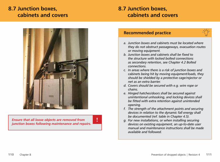
110 Chapter 8 Prevention of dropped objects | Revision 4 111
8.7 Junction boxes,
cabinets and covers 8.7 Junction boxes,
cabinets and covers
Ensure that all loose objects are removed from junction boxes following maintenance and repairs.
!
a. Junction boxes and cabinets must be located where they do not obstruct passageways, evacuation routes or moving equipment.
b. Junction boxes and cabinets shall be fixed to the structure with locked bolted connections as secondary retention, see Chapter 4.2 Bolted connections.
c. In areas where there is a risk of junction boxes and cabinets being hit by moving equipment/loads, they should be shielded by a protective cage/rejector or net as an extra barrier.
d. Covers should be secured with e.g. wire rope or chains.
e. Hinged hatches/doors shall be secured against unintentional unhooking, and locking devices shall be fitted with extra retention against unintended opening.
f. The strength of the attachment points and securing devices in relation to the dynamic fall energy shall be documented (ref. table in Chapter 4.5).
g. For new installations, or when installing securing devices on existing equipment, an up-to-date user manual and maintenance instructions shall be made available and followed.
Recommended practice
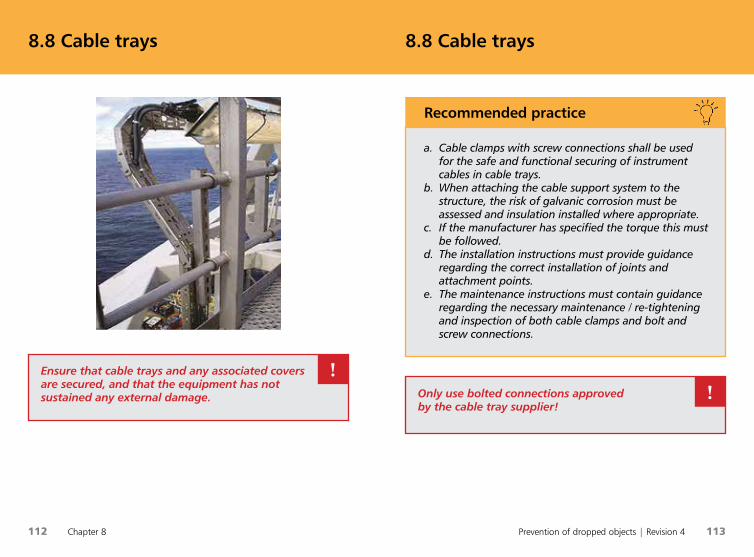
112 Chapter 8 Prevention of dropped objects | Revision 4 113
8.8 Cable trays 8.8 Cable trays
Ensure that cable trays and any associated covers are secured, and that the equipment has not sustained any external damage.
!
a. Cable clamps with screw connections shall be used for the safe and functional securing of instrument cables in cable trays.
b. When attaching the cable support system to the structure, the risk of galvanic corrosion must be assessed and insulation installed where appropriate.
c. If the manufacturer has specified the torque this must be followed.
d. The installation instructions must provide guidance regarding the correct installation of joints and attachment points.
e. The maintenance instructions must contain guidance regarding the necessary maintenance / re-tightening and inspection of both cable clamps and bolt and screw connections.
Recommended practice
Only use bolted connections approved by the cable tray supplier!
!
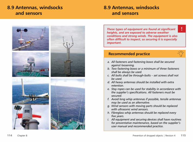
114 Chapter 8 Prevention of dropped objects | Revision 4 115
8.9 Antennas, windsocks
and sensors8.9 Antennas, windsocks
and sensors
a. All fasteners and fastening bows shall be secured against loosening.
b. Two fastening bows or a minimum of three fasteners shall be always be used.
c. All bolts shall be through-bolts – set screws shall not be used.
d. All heavy antennas should be installed with extra retention.
e. Stay ropes can be used for stability in accordance with the supplier’s specifications. All fasteners must be secured.
f. Avoid long whip antennas if possible, tensile antennas may be used as an alternative.
g. Wind sensors with moving parts should be replaced with ultrasonic wind sensors.
h. Fibreglass whip antennas should be replaced every five years.
i. All equipment and securing devices shall have routines for preventative maintenance, based on the supplier’s user manual and recommended practice.
Recommended practice
These types of equipment are found at significant heights, and are exposed to adverse weather conditions and strong winds. The equipment is also often difficult to inspect, so securing it is especially important.
!
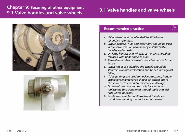
116 Chapter 9 Prevention of dropped objects | Revision 4 117
9.1 Valve handles and valve wheels Chapter 9: Securing of other equipment9.1 Valve handles and valve wheels
a. Valve wheels and handles shall be fitted with secondary retention.
b. Where possible, nuts and cotter pins should be used in the valve stem on permanently installed valve handles and wheels.
c. On large handles and wheels, cotter pins should be replaced with bolts and lock nuts.
d. Moveable handles or wheels should be secured when in use.
e. When not in use, handles and wheels should be stored in a dedicated location and be secured against falling.
f. If Seeger rings are used for locking/securing, frequent inspections/maintenance should be carried out to check for corrosion and/or mechanical damage.
g. On wheels that are secured only by a set screw, replace the set screws with through-bolts and lock nuts where possible.
h. Safety wire may be an alternative if the above-mentioned securing methods cannot be used.
Recommended practice
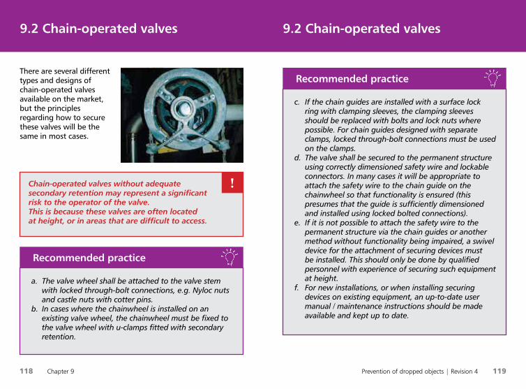
118 Chapter 9 Prevention of dropped objects | Revision 4 119
There are several different types and designs of chain-operated valves available on the market, but the principles regarding how to secure these valves will be the same in most cases.
9.2 Chain-operated valves9.2 Chain-operated valves
a. The valve wheel shall be attached to the valve stem with locked through-bolt connections, e.g. Nyloc nuts and castle nuts with cotter pins.
b. In cases where the chainwheel is installed on an existing valve wheel, the chainwheel must be fixed to the valve wheel with u-clamps fitted with secondary retention.
Recommended practice
Chain-operated valves without adequate secondary retention may represent a significant risk to the operator of the valve. This is because these valves are often located at height, or in areas that are difficult to access.
!
c. If the chain guides are installed with a surface lock ring with clamping sleeves, the clamping sleeves should be replaced with bolts and lock nuts where possible. For chain guides designed with separate clamps, locked through-bolt connections must be used on the clamps.
d. The valve shall be secured to the permanent structure using correctly dimensioned safety wire and lockable connectors. In many cases it will be appropriate to attach the safety wire to the chain guide on the chainwheel so that functionality is ensured (this presumes that the guide is sufficiently dimensioned and installed using locked bolted connections).
e. If it is not possible to attach the safety wire to the permanent structure via the chain guides or another method without functionality being impaired, a swivel device for the attachment of securing devices must be installed. This should only be done by qualified personnel with experience of securing such equipment at height.
f. For new installations, or when installing securing devices on existing equipment, an up-to-date user manual / maintenance instructions should be made available and kept up to date.
Recommended practice
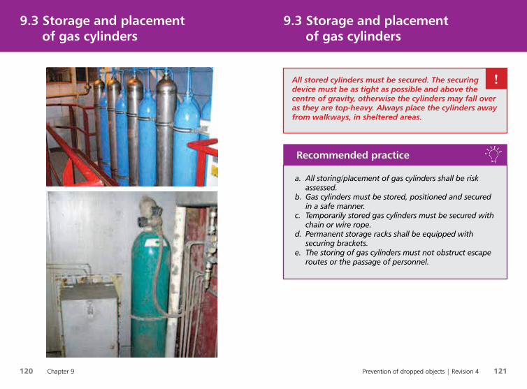
120 Chapter 9 Prevention of dropped objects | Revision 4 121
9.3 Storage and placement
of gas cylinders 9.3 Storage and placement
of gas cylinders
a. All storing/placement of gas cylinders shall be risk assessed.
b. Gas cylinders must be stored, positioned and secured in a safe manner.
c. Temporarily stored gas cylinders must be secured with chain or wire rope.
d. Permanent storage racks shall be equipped with securing brackets.
e. The storing of gas cylinders must not obstruct escape routes or the passage of personnel.
Recommended practice
All stored cylinders must be secured. The securing device must be as tight as possible and above the centre of gravity, otherwise the cylinders may fall over as they are top-heavy. Always place the cylinders away from walkways, in sheltered areas.
!
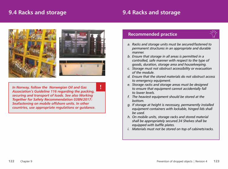
122 Chapter 9 Prevention of dropped objects | Revision 4 123
9.4 Racks and storage9.4 Racks and storage
a. Racks and storage units must be secured/fastened to permanent structures in an appropriate and durable manner.
b. Ensure that storage in all areas is permitted in a controlled, safe manner with respect to the type of goods, duration, storage area and housekeeping.
c. Storage must not obstruct accessibility or evacuation of the module.
d. Ensure that the stored materials do not obstruct access to emergency equipment.
e. Storage racks and storage areas must be designed to ensure that equipment cannot accidentally fall to lower levels.
f. The heaviest equipment should be stored at the bottom.
g. If storage at height is necessary, permanently installed equipment containers with lockable, hinged lids shall be used.
h. On mobile units, storage racks and stored material shall be appropriately secured.34 Shelves shall be equipped with baffle plates.
i. Materials must not be stored on top of cabinets/racks.
Recommended practice
In Norway, follow the Norwegian Oil and Gas Association’s Guideline 116 regarding the packing, securing and transport of loads. See also Working Together for Safety Recommendation 038N/2017: Seafastening on mobile offshore units. In other countries, use appropriate regulations or guidance.
!
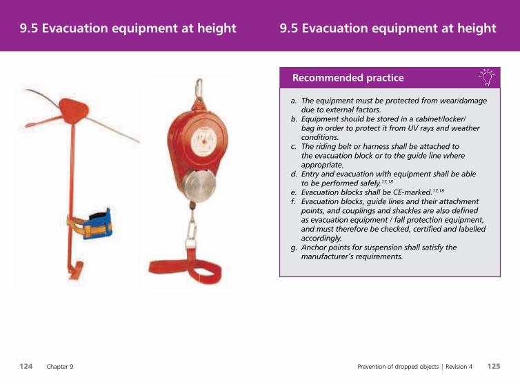
124 Chapter 9 Prevention of dropped objects | Revision 4 125
9.5 Evacuation equipment at height 9.5 Evacuation equipment at height
a. The equipment must be protected from wear/damage due to external factors.
b. Equipment should be stored in a cabinet/locker/bag in order to protect it from UV rays and weather conditions.
c. The riding belt or harness shall be attached to the evacuation block or to the guide line where appropriate.
d. Entry and evacuation with equipment shall be able to be performed safely.17,18
e. Evacuation blocks shall be CE-marked.17,18
f. Evacuation blocks, guide lines and their attachment points, and couplings and shackles are also defined as evacuation equipment / fall protection equipment, and must therefore be checked, certified and labelled accordingly.
g. Anchor points for suspension shall satisfy the manufacturer’s requirements.
Recommended practice
126 Chapter 10 Prevention of dropped objects | Revision 4 127
AISI: American Iron and Steel Institute.
Anchoring device: Equipment attached to the structure, which can then be used to secure equipment. Also applies in the securing of personnel.
API: American Petroleum Institute, issues production standards for equipment used in the oil industry.
Atil: Arbeidstilsynet (The Norwegian Labour Inspection Authority).
Attachment point (on equipment): Point/component intended for attaching a securing strap. Tools/belts/bags shall feature attachment points. These shall have defined load limits. Here, the term ‘attachment point’ (on tools/equipment) refers to the component installed on the equipment by the manufacturer, or manufactured in order to allow tools, equipment and other loose objects to be secured against being dropped using an anchored strap or similar.
Attachment point (on structure): Structure to which an anchoring device may be attached, e.g. H-beam. The attachment point must be strong enough to tolerate a tug in connection with a fall – check the manufacturer’s user guide. Also used to describe points on a harness intended for the connection of fall protection equipment (from NS 9610).
Barrier function: The task or role of a barrier.
CCTV: (Closed-circuit television) surveillance camera.
Clearance height: The minimum clearance height above an obstacle that is necessary to prevent a collision in the event of a free fall arrested by a given fall arrest system.
Competent person: A person who can document practical and theoretical knowledge within a particular area or discipline.
DIBt: Deutsches Institut für Bautechnik.
1.4 VerdikjedenChapter 10: Terms and abbreviations Chapter 10: Terms and abbreviations
DNV: Det Norske Veritas.
DO: Dropped object, i.e. an object that moves from one level to another in an uncontrolled manner. Note that DO may also occur under other circumstances, not only during work at height. Suspended equipment, pipes and materials that fall or detach from their fastenings may also release fall energy and should therefore also be treated as dropped objects. The difference in the height of the object’s centre of gravity before and after tipping over / falling is then used as the height.
Documentable: Equipment is labelled in a way that ensures traceability to the manufacturer or importer, and provides information including the load, area of use and product standard.
Documented training: Training through which it can be documented that the person who shall use the equipment has received practical and theoretical training that provides knowledge of the equipment’s assembly, operation, use and areas of application, as well as inspection and maintenance in accordance with the requirements set for the safe use and operation of the equipment in regulations and user manuals.
DROPS: Dropped Object Prevention Scheme, a global industry initiative that focuses on the prevention of dropped objects (www.dropsonline.org).
EN: European Standards, issued by the European Committee for Standardisation (CEN) and adopted by one of the three recognised European standardisation bodies – CEN, CENELEC or ETSI.
Extra retention (double retention / extra barrier): Securing devices that provide an independent barrier when affixed to the surrounding structure in order to catch components in the event that the primary installation fails, e.g. wire rope or net.

128 Chapter 10 Prevention of dropped objects | Revision 4 129
1.4 VerdikjedenChapter 10: Terms and abbreviations Chapter 10: Terms and abbreviations
Rated Capacity: Maximum load that a lifting appliance is designed to lift under specific conditions. Normally this corresponds to SWL.
Risk: An expression of the hazard that an undesirable incident represents to people, the environment or material assets. The risk is expressed as the probability of an accident occurring, as well as its consequences.
Risk evaluation: A systematic method of describing and/or calculating risk to personnel, the environment and equipment. A risk analysis is performed through the mapping of undesirable incidents and their causes and consequences.
RNNP: Trends in the risk level in petroleum activity.
Safety wire: Wire that secures an object at height to an attachment point.
Secondary retention: The securing of a primary installation in order to achieve an extra level of safety, e.g. the locking of a bolted connection to prevent loss of pre-tension, securing components against moving.
Securing device: A device (line – strap/wire/chain, etc.) that secures an object at height to an attachment point.
Securing strap: A strap that secures an object at height to an attachment point.
SfS: Samarbeid for Sikkerhet (Working Together for Safety) – one of the most extensive collaborative projects to be implemented within the field of health, safety and environment (HSE) in the oil and gas industry.
SWL: Safe working load. SWL normally corresponds to Rated capacity (R). This handbook only uses SWL for lifting appliances.
TÜV: Technischer Überwachungsverein.
Fall arrest blocks: Fall arrest device that ensures a short fall. Provides a limited working radius, max. 30° from the vertical axis. The block and line must not sit against any edges or other structure. Most fall arrest blocks are not designed or certified for the line to sit against an edge in the event of a fall.
Fall arrest system: A system that arrests a free fall.
Fall height: The length of the drop before tug/arresting.
Fall prevention system: A system that shall ensure a free fall cannot occur. Also known as a position-limiting system. The individual’s radius of action is so limited that the individual is unable to fall.
F.E.M: European Federation of Material Handling.
HSE: Health, safety and environment.
ISO: International Organization for Standardization.
Lifting equipment: Umbrella term for lifting gear, lifting devices and lifting components, used in combination or individually.
OEM: Original Equipment Manufacturer.
Primary installation: Equipment installed and secured against being dropped in accordance with standard procedures for screws, bolts, welding, etc. (primary barrier against DO).
Extra retention (double retention / extra barrier): Securing devices that provide an independent barrier when affixed to the surrounding structure in order to catch components in the event that the primary installation fails, e.g. wire rope or net.
Secondary retention: The securing of a primary installation in order to achieve an extra level of safety, e.g. the locking of a bolted connection to prevent loss of pre-tension, securing components against moving.
Ptil (PSA): Petroleumstilsynet (The Petroleum Safety Authority).
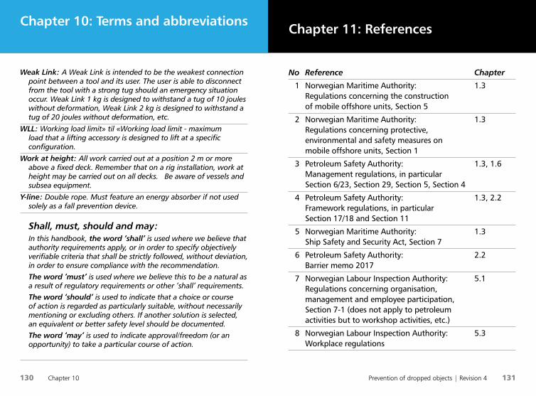
Prevention of dropped objects | Revision 4 131
130 Chapter 10
Chapter 11: References Chapter 10: Terms and abbreviations
Weak Link: A Weak Link is intended to be the weakest connection point between a tool and its user. The user is able to disconnect from the tool with a strong tug should an emergency situation occur. Weak Link 1 kg is designed to withstand a tug of 10 joules without deformation, Weak Link 2 kg is designed to withstand a tug of 20 joules without deformation, etc.
WLL: Working load limit» til «Working load limit - maximum load that a lifting accessory is designed to lift at a specific configuration.
Work at height: All work carried out at a position 2 m or more above a fixed deck. Remember that on a rig installation, work at height may be carried out on all decks. Be aware of vessels and subsea equipment.
Y-line: Double rope. Must feature an energy absorber if not used solely as a fall prevention device.
Shall, must, should and may: In this handbook, the word ‘shall’ is used where we believe that authority requirements apply, or in order to specify objectively verifiable criteria that shall be strictly followed, without deviation, in order to ensure compliance with the recommendation. The word ‘must’ is used where we believe this to be a natural as a result of regulatory requirements or other ‘shall’ requirements. The word ‘should’ is used to indicate that a choice or course of action is regarded as particularly suitable, without necessarily mentioning or excluding others. If another solution is selected, an equivalent or better safety level should be documented. The word ‘may’ is used to indicate approval/freedom (or an opportunity) to take a particular course of action.
No Reference Chapter
1 Norwegian Maritime Authority: 1.3 Regulations concerning the construction of mobile offshore units, Section 5
2 Norwegian Maritime Authority: 1.3 Regulations concerning protective, environmental and safety measures on mobile offshore units, Section 1
3 Petroleum Safety Authority: 1.3, 1.6 Management regulations, in particular Section 6/23, Section 29, Section 5, Section 4
4 Petroleum Safety Authority: 1.3, 2.2 Framework regulations, in particular Section 17/18 and Section 11
5 Norwegian Maritime Authority: 1.3 Ship Safety and Security Act, Section 7
6 Petroleum Safety Authority: 2.2 Barrier memo 2017
7 Norwegian Labour Inspection Authority: 5.1 Regulations concerning organisation, management and employee participation, Section 7-1 (does not apply to petroleum activities but to workshop activities, etc.)
8 Norwegian Labour Inspection Authority: 5.3 Workplace regulations
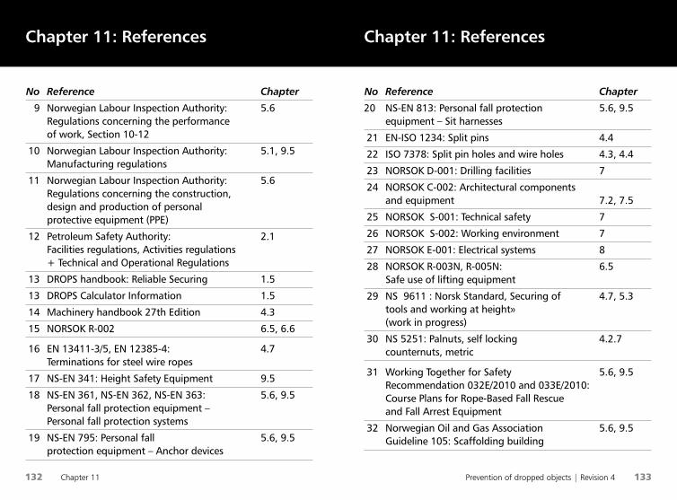
132 Chapter 11 Prevention of dropped objects | Revision 4 133
Chapter 11: References Chapter 11: References
No Reference Chapter
20 NS-EN 813: Personal fall protection 5.6, 9.5 equipment – Sit harnesses
21 EN-ISO 1234: Split pins 4.4
22 ISO 7378: Split pin holes and wire holes 4.3, 4.4
23 NORSOK D-001: Drilling facilities 7
24 NORSOK C-002: Architectural components and equipment 7.2, 7.5
25 NORSOK S-001: Technical safety 7
26 NORSOK S-002: Working environment 7
27 NORSOK E-001: Electrical systems 8
28 NORSOK R-003N, R-005N: 6.5 Safe use of lifting equipment
29 NS 9611 : Norsk Standard, Securing of 4.7, 5.3 tools and working at height» (work in progress)
30 NS 5251: Palnuts, self locking 4.2.7 counternuts, metric
31 Working Together for Safety 5.6, 9.5 Recommendation 032E/2010 and 033E/2010: Course Plans for Rope-Based Fall Rescue and Fall Arrest Equipment
32 Norwegian Oil and Gas Association 5.6, 9.5 Guideline 105: Scaffolding building
No Reference Chapter
9 Norwegian Labour Inspection Authority: 5.6 Regulations concerning the performance of work, Section 10-12
10 Norwegian Labour Inspection Authority: 5.1, 9.5 Manufacturing regulations
11 Norwegian Labour Inspection Authority: 5.6 Regulations concerning the construction, design and production of personal protective equipment (PPE)
12 Petroleum Safety Authority: 2.1 Facilities regulations, Activities regulations + Technical and Operational Regulations
13 DROPS handbook: Reliable Securing 1.5
13 DROPS Calculator Information 1.5
14 Machinery handbook 27th Edition 4.3
15 NORSOK R-002 6.5, 6.6
16 EN 13411-3/5, EN 12385-4: 4.7 Terminations for steel wire ropes
17 NS-EN 341: Height Safety Equipment 9.5
18 NS-EN 361, NS-EN 362, NS-EN 363: 5.6, 9.5 Personal fall protection equipment – Personal fall protection systems
19 NS-EN 795: Personal fall 5.6, 9.5 protection equipment – Anchor devices
135
Notes
134
Chapter 11: References
No Reference Chapter
33 Norwegian Oil and Gas Association 5.6, 9.5 Guideline 113: Fall protection and rescue
34 Working Together for Safety 6.8, 9.4 Recommendation 038E/2017: Seafastening on mobile offshore units
35 The Machinery Directive is an EU directive 5.3 incorporated into Norwegian legislation as the Machinery Regulations
36 Samarbeidforsikkerhet.no 1.5 Notes on fall energy
136 137
Notes Notes

139138
NotesNotes

140 Kapittel 1
Never let your tools
off the leash!
www.samarbeidforsikkerhet.no