Embed Size (px)
DESCRIPTION
Revised Diagnostics Plan. D. Johnson, B. Stratton, E. Lazarus, H. Takahashi, E. Fredrickson, M. Zarnstorff. Outline. Diagnostics included in the project Rogowski coils to measure I p , and ‘trapped’ magnetics fast visible camera to verify plasma shape - PowerPoint PPT Presentation
Citation preview

October 16, 2003 D. Johnson 1
NCSX
Revised Diagnostics Plan
D. Johnson, B. Stratton, E. Lazarus, H. Takahashi, E. Fredrickson, M. Zarnstorff

October 16, 2003 D. Johnson 2
NCSX
• Diagnostics included in the project– Rogowski coils to measure Ip, and ‘trapped’ magnetics– fast visible camera to verify plasma shape– e-beam mapping to confirm vacuum field configuration– diagnostic integration
• Will rely on Research Preparation to fund design and early fabrication of diagnostic upgrades for Phase III and IV.
Outline
October 16, 2003 D. Johnson 3
NCSX“Trapped” magnetic sensors
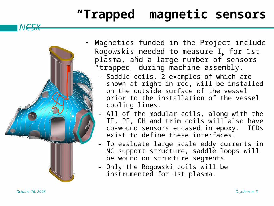
• Magnetics funded in the Project include Rogowskis needed to measure IP for 1st plasma, and a large number of sensors “trapped” during machine assembly.– Saddle coils, 2 examples of which are shown at right
in red, will be installed on the outside surface of the vessel prior to the installation of the vessel cooling lines.
– All of the modular coils, along with the TF, PF, OH and trim coils will also have co-wound sensors encased in epoxy. ICDs exist to define these interfaces.
– To evaluate large scale eddy currents in MC support structure, saddle loops will be wound on structure segments.
– Only the Rogowski coils will be instrumented for 1st plasma.

October 16, 2003 D. Johnson 4
NCSXFast visible camera
• For 1st plasma– Fast visible camera will be
mounted behind window at a tangential NB port
– Camera and local magnetic shield will be supported directly from port
– Camera will have full frame rate of ~ 1khz to resolve startup plasma

October 16, 2003 D. Johnson 5
NCSXDefining field line mapping requirements
Perfectly AlignedSector-1 DisplacedVertically by 2 mm
• Modular coils only energized in series for this study• Rigid-body displacement of a whole sector• Islands (2/5) clearly identifiable for 2 mm displacement • Not enough information available to unequivocally identify types
of misalignment - will likely have to rely on careful metrology.• Study shows beam detection at the v=.5 symmetry plane will
produce most defined islands
PIES Code

October 16, 2003 D. Johnson 6
NCSXe-Beam mapping
• After first plasma campaign and before cryostat is installed, e-beam mapping will be performed to confirm the vacuum magnetic field configuration.
• A conventional system is budgeted, consisting of an electron gun mounted on a probe, a phosphor-coated mesh mounted at v=.5 symmetry plane with a short range of motion, and a CCD camera viewing through a vacuum window.
• Also considering other approaches for detection, including a movable phosphor-coated rod, and a rod featuring a phosphor-coated fiber array for much higher optical throughput.

October 16, 2003 D. Johnson 7
NCSXFlared ports are example of integration
• New flared port design offers excellent, wide angle, high throughput access to v=0 symmetry plane.
• For several optical diagnostics, flared design provides ≥ x2 improvement.
• Note large radially elongated vertical ports also in v=0 plane.
Flared ports
October 16, 2003 D. Johnson 8
NCSX
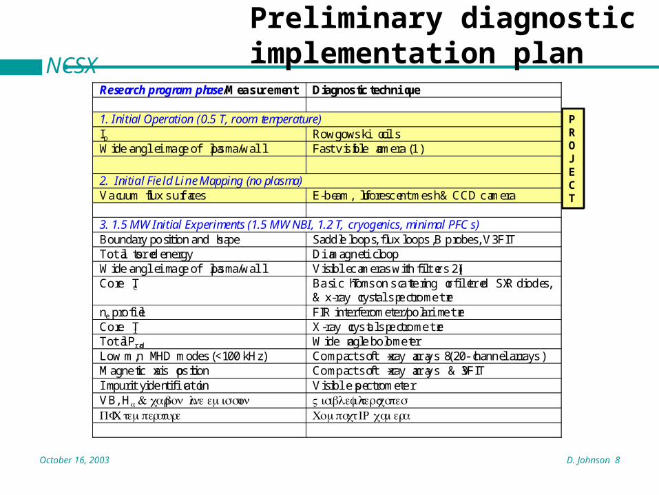
Preliminary diagnostic implementation plan
Research program phase/Measurement Diagnostic technique
1. Initial Operation (0.5 T, room temperature)Ip Rowgowski coilsWide-angle image of plasma/wall Fast visible camera (1)
2. Initial Field Line Mapping (no plasma)Vacuum flux surfaces E-beam, fluorescent mesh & CCD camera
3. 1.5 MW Initial Experiments (1.5 MW NBI, 1.2 T, cryogenics, minimal PFCs)Boundary position and shape Saddle loops, flux loops, B probes, V3FITTotal stored energy Diamagnetic loopWide-angle image of plasma/wall Visible cameras with filters (2)Core Te Basic Thomson scattering or filtered SXR diodes,
& x-ray crystal spectrometerne profile FIR interferometer/polarimeterCore Ti X-ray crystal spectrometerTotal Prad Wide angle bolometerLow m,n MHD modes (<100 kHz) Compact soft x-ray arrays (8 20-channel arrays)Magnetic axis position Compact soft x-ray arrays & V3FITImpurity identification Visible spectrometerVB, Hα & carbo n lin eemission Visible filterscopesPF C temperature Compact IR camera
PROJECT
October 16, 2003 D. Johnson 9
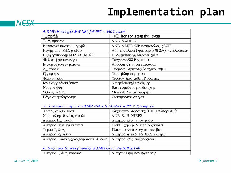
NCSXImplementation plan
4. 3 MW Heating (3 MW NBI, full PFCs, 350 C bake)Te profile Full Thomson scattering systemTi, vθ profiles DN & B CHERSRotationa l transform profile DN & B MSE, FI R inter./polar., V3FITHighe rm,n MHD modes Additional sof t -x ra yarrays (8 20-channel arrays)High-frequency MHD (<5 MHz) High-frequency Mirno v coilsFlu xsurface topology Tangential SXR cameraImpurity concentrations Absolut eVU V spectroscopyZeff profile Thomso n scatterin gdetecto r systemPrad profile Cor e bolometer arrayFast io n loss Fast io n lo ss probe, I R cameraIo nenergy distribution Neutral particle analyzerNeutron flux Epitherm alneutro ndetectorSOL ne and Te Movabl eLangmui r probeEd geneutral pressure Fast pressur egauges
5. Confinemen & t β pu (sh 3 MW NBI & 6 MW NBI or ,RF 2 T, diverto )rCor ene fluctuations Fluctuatio n diagnosti c (HIB P and/o r BE )SCor e heli um densit yprofile DN & B H e CHERSDiverto r Prad profile Diverto r bolometer arraysDiverto r plat e temperature Fast I R camer a& thermocouplesTarget Te & ne Plate-mounted Langmui r probesDiverto r recycling Diverto r filtered 1- DCC D cameraDiverto r Impurit yconcentratio & ns flows Diverto r VU V spectroscopy
6. Long puls e(Existing heatin & g 3 MWlon gpuls eNBI o r RF)Diverto r Te & ne profiles Diverto r Thomso nscattering

October 16, 2003 D. Johnson 10
NCSXFitting it all together
• Need to assess diagnostic needs prior to 1st plasma for the design and early fabrication of long-lead diagnostic systems for phases III & IV.
• Over the next couple of months, B. Stratton and I will put together a conceptual level, resource loaded schedule through FY07, based on the implementation plan.
FY-04 FY-05 FY-06 FY-07 FY-08 FY-09
Program Funding ($M) FY04 FY05 FY06 FY07
Research Preparation 0.8 1.7 2.1 9.9