Embed Size (px)
Citation preview

1
1/2017 Version 9.3PCS Refresher Training Webinar
For Software Version: 9.3Copyright © 2017 ProModel Corporation
556 E Technology WayOrem, UT 84097
801-223-4600
This publication may not be reproduced in whole or in part in any form or by any means, electronic or mechanical, including photocopying, recording, or otherwise, without prior written permission of ProModel Corporation. ProModel and MedModel are registered trademarks of ProModel Corporation.
This course is intended for previous
Users of Process Simulator who have
completed Basic Training but may not
have used the software for a while.
Our hope is that this training will help
these Users “brush up” on their skills
so they can again use the software to
benefit their business.
Instructor Info:
Dave Tucker, LSSMBB
ProModel Senior Consultant
Office: 321.567.5642

2
1. Review the basic features of Process Simulator
2. Provide demonstrations of how to use PCS
3. Show model examples
4. Answer Attendees’ questions (as time allows)
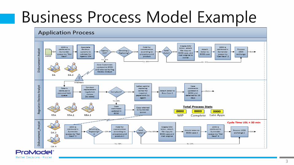
3

4
1. How to use Process Simulator in Visio
2. Activities, Entities, & Arrivals
3. Routings
4. Resources & how to use them
5. User-Defined Expressions
6. Output Viewer
7. Scenarios
Sections

5
1/2017 Version 9.3PCS Refresher Training Webinar
For Software Version: 9.3Copyright © 2017 ProModel Corporation
556 E Technology WayOrem, UT 84097
801-223-4600
This publication may not be reproduced in whole or in part in any form or by any means, electronic or mechanical, including photocopying, recording, or otherwise, without prior written permission of ProModel Corporation. ProModel and MedModel are registered trademarks of ProModel Corporation.
6
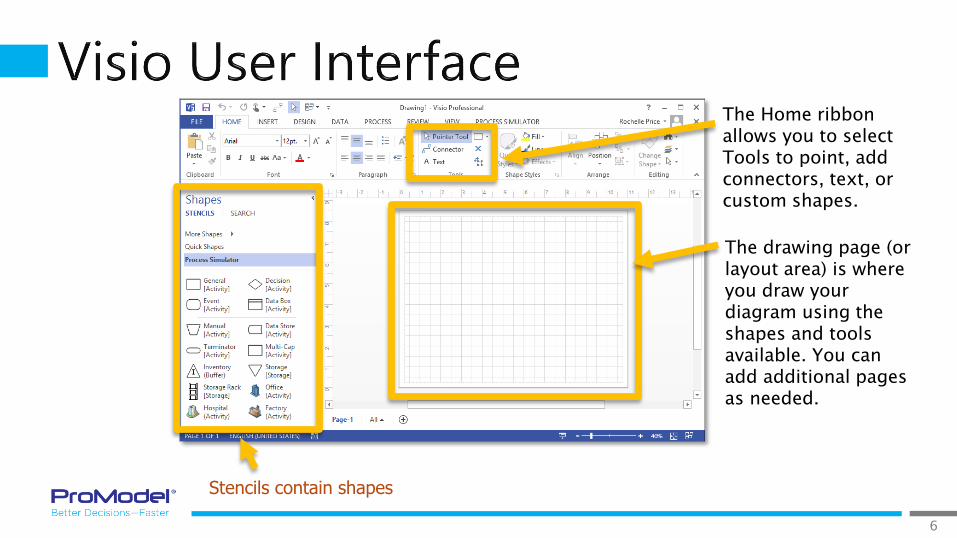
Stencils contain shapes
The Home ribbon allows you to select Tools to point, add connectors, text, or custom shapes.
The drawing page (or layout area) is where you draw your diagram using the shapes and tools available. You can add additional pages as needed.
7
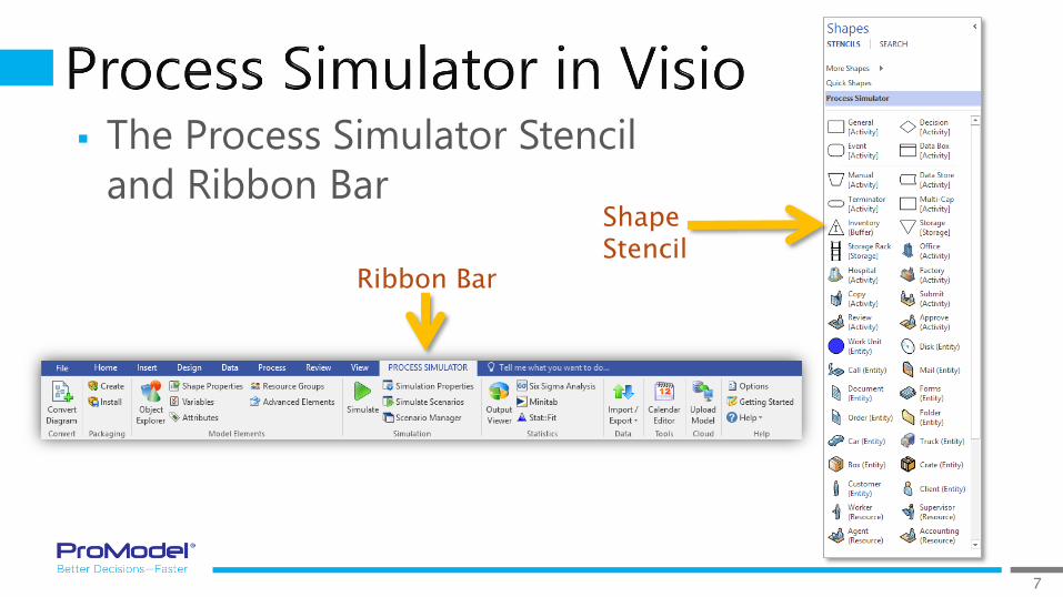
The Process Simulator Stencil
and Ribbon BarShape Stencil
Ribbon Bar
8
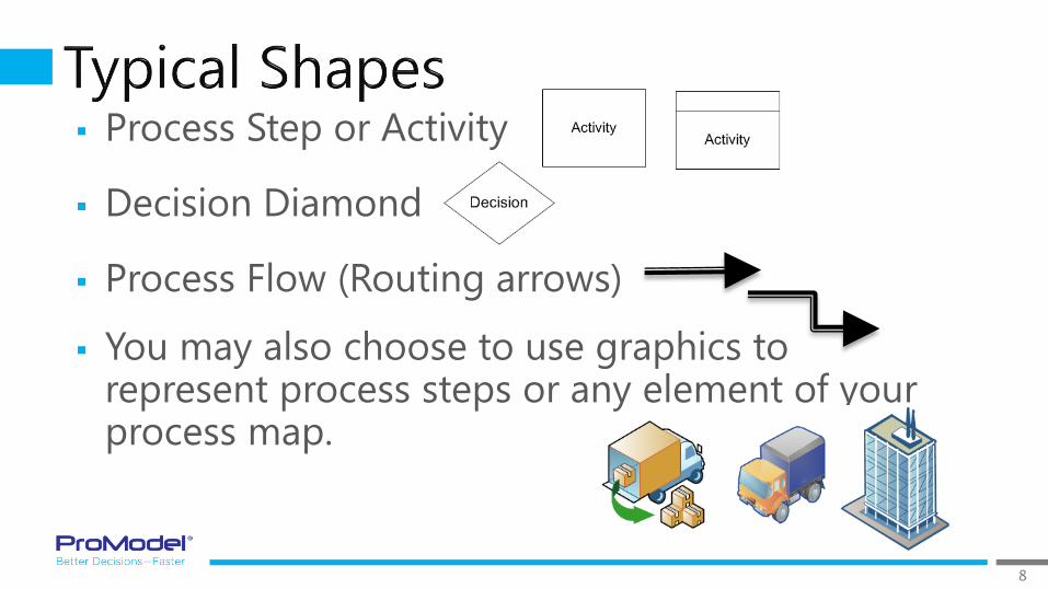
Process Step or Activity
Decision Diamond
Process Flow (Routing arrows)
You may also choose to use graphics to represent process steps or any element of your process map.
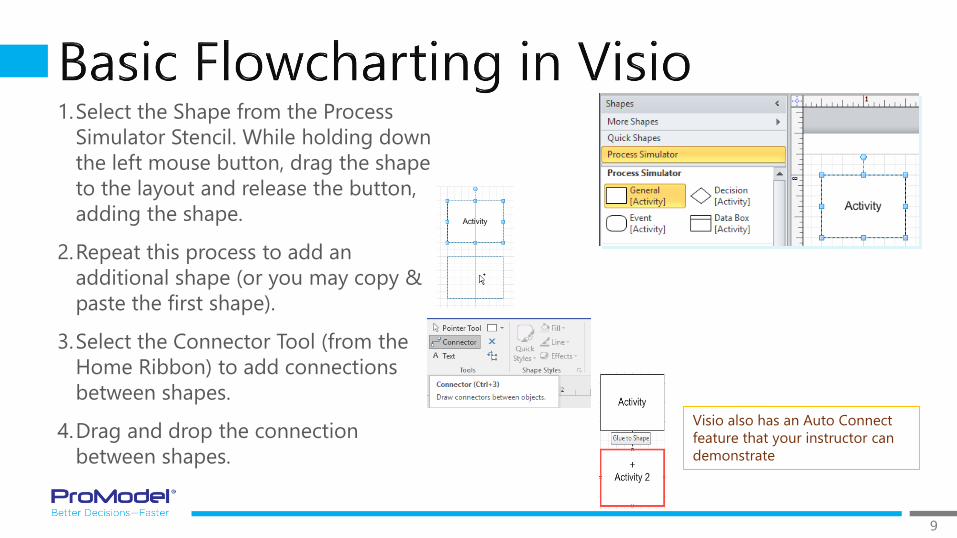
9
1.Select the Shape from the Process
Simulator Stencil. While holding down
the left mouse button, drag the shape
to the layout and release the button,
adding the shape.
2.Repeat this process to add an
additional shape (or you may copy &
paste the first shape).
3.Select the Connector Tool (from the
Home Ribbon) to add connections
between shapes.
4.Drag and drop the connection
between shapes.
Visio also has an Auto Connect
feature that your instructor can
demonstrate
10

11
Check your Simulation Properties by right-clicking on the Layout and selecting Simulation Properties.
Enter the number of replications. Then click OK.
Click on the Simulate button to start the simulation.
12
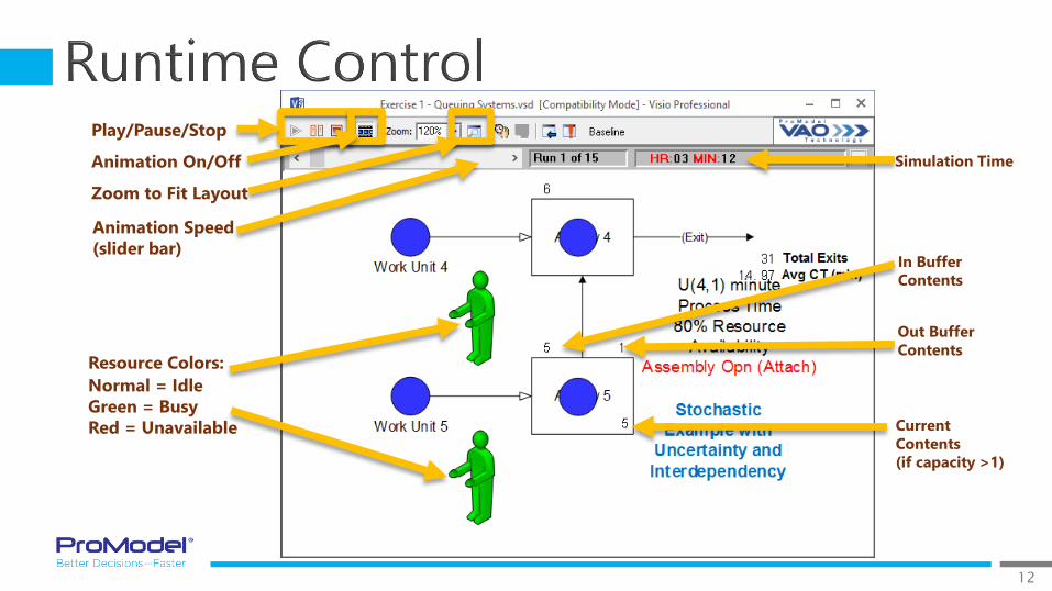
Play/Pause/Stop
Animation On/Off
Zoom to Fit Layout
In Buffer
Contents
Out Buffer
Contents
Simulation Time
Resource Colors:
Normal = Idle
Green = Busy
Red = Unavailable Current
Contents
(if capacity >1)
Animation Speed
(slider bar)
13
1/2017 Version 9.3PCS Refresher Training Webinar
For Software Version: 9.3Copyright © 2017 ProModel Corporation
556 E Technology WayOrem, UT 84097
801-223-4600
This publication may not be reproduced in whole or in part in any form or by any means, electronic or mechanical, including photocopying, recording, or otherwise, without prior written permission of ProModel Corporation. ProModel and MedModel are registered trademarks of ProModel Corporation.

14
EntityArrival Activities
Routings
Resource
15
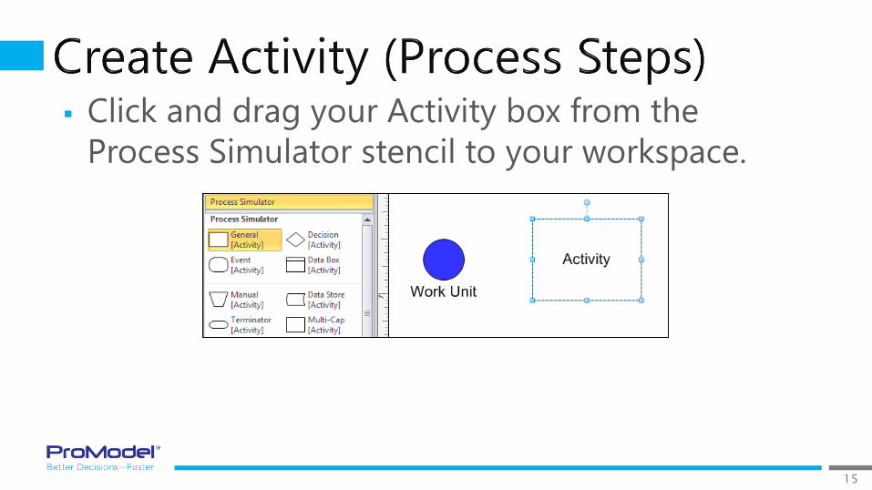
Click and drag your Activity box from the
Process Simulator stencil to your workspace.

16
17
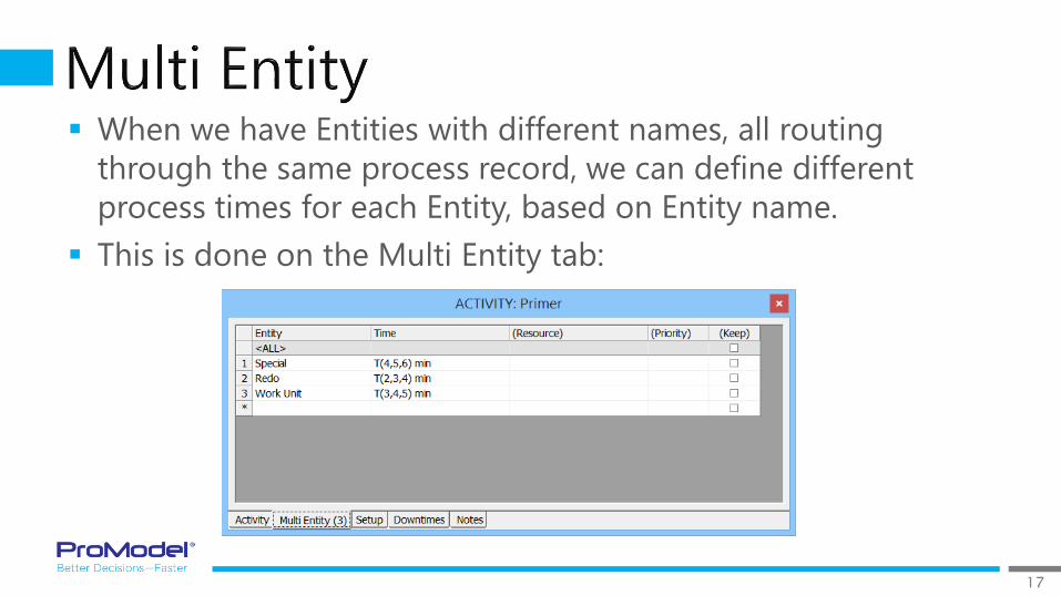
When we have Entities with different names, all routing
through the same process record, we can define different
process times for each Entity, based on Entity name.
This is done on the Multi Entity tab:

18
Left-click and drag an Entity from
the Process Simulator stencil to
your layout.
After placing the entity on your
layout, you can right-click on the
Entity to bring up the Properties
dialog.
19
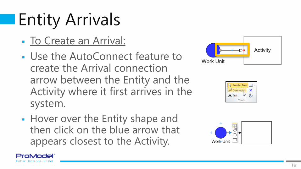
To Create an Arrival:
Use the AutoConnect feature to create the Arrival connection arrow between the Entity and the Activity where it first arrives in the system.
Hover over the Entity shape and then click on the blue arrow that appears closest to the Activity.
20
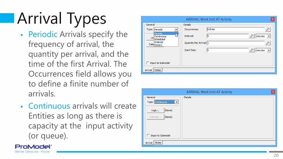
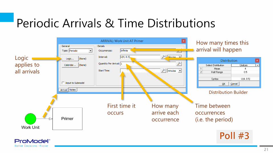
Periodic Arrivals specify the
frequency of arrival, the
quantity per arrival, and the
time of the first Arrival. The
Occurrences field allows you
to define a finite number of
arrivals.
Continuous arrivals will create
Entities as long as there is
capacity at the input activity
(or queue).
21
Logic
applies to
all arrivals
First time it
occurs
How many times this
arrival will happen
Time between
occurrences
(i.e. the period)
How many
arrive each
occurrence
Distribution Builder

22
Scheduled Arrivals allow
you to specify the week,
day, and time of the
Arrival.
Scheduled Arrivals may
also be defined by
calendar date and time
Multiple Scheduled Arrivals may be used
for an Entity entering a Single Activity!

23
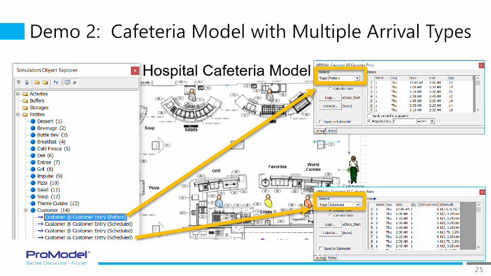
Pattern Arrivals provide additional flexibility and
functionality beyond the Scheduled Arrivals definitions.
In this example, all the Orders show up throughout the
day beginning at 8:00 AM. Pattern Arrivals allow us to
spread them out randomly throughout the day.
Order Incoming
Pattern
Only 1 Pattern Arrival can be used for
an Entity entering a Single Activity!
24
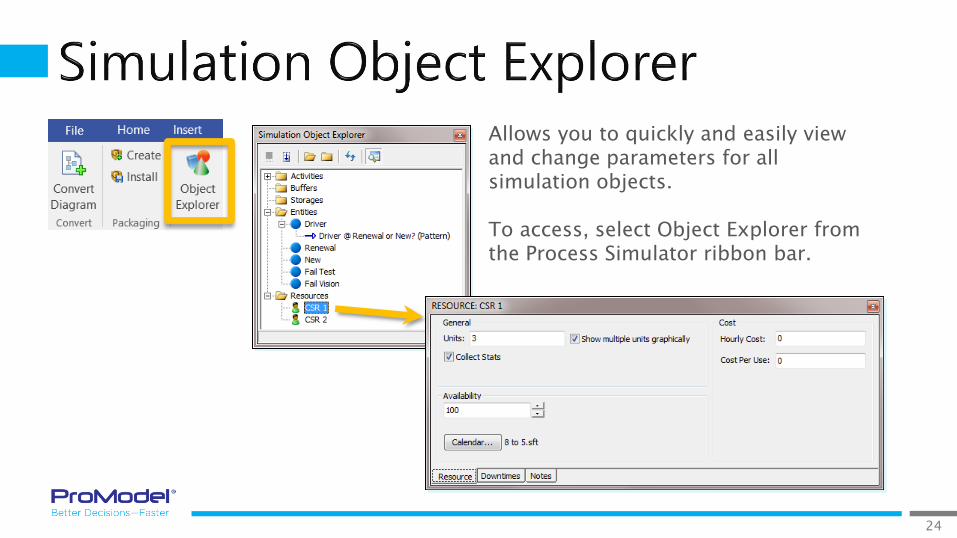
Allows you to quickly and easily view and change parameters for all simulation objects.
To access, select Object Explorer from the Process Simulator ribbon bar.
25

26
1/2017 Version 9.3PCS Refresher Training Webinar
For Software Version: 9.3Copyright © 2017 ProModel Corporation
556 E Technology WayOrem, UT 84097
801-223-4600
This publication may not be reproduced in whole or in part in any form or by any means, electronic or mechanical, including photocopying, recording, or otherwise, without prior written permission of ProModel Corporation. ProModel and MedModel are registered trademarks of ProModel Corporation.

27
Routings define the process flow from activity
to activity, and to “Exit” (where the entity leaves
the system).
Use the AutoConnect to create the routing
from Activity to Exit (hover over the Activity
and click and drag on a blue arrow that
appears).
28
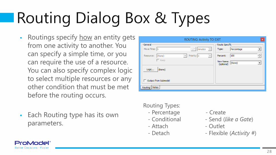
Routings specify how an entity gets
from one activity to another. You
can specify a simple time, or you
can require the use of a resource.
You can also specify complex logic
to select multiple resources or any
other condition that must be met
before the routing occurs.
Each Routing type has its own
parameters.
Routing Types:
- Percentage
- Conditional
- Attach
- Detach
- Create
- Send (like a Gate)
- Outlet
- Flexible (Activity #)

29
In cases where the routing decision may be more complicated
than percentage based, we can route based on a condition
being true such as an entity name or entity’s attribute value, or
even the current value of a global variable.
This allows us to control entities destinations in Activity Logic
or anywhere upstream in the process.
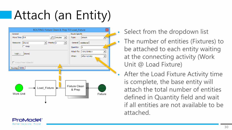
30
Select from the dropdown list
The number of entities (Fixtures) to
be attached to each entity waiting
at the connecting activity (Work
Unit @ Load Fixture)
After the Load Fixture Activity time
is complete, the base entity will
attach the total number of entities
defined in Quantity field and wait
if all entities are not available to be
attached.
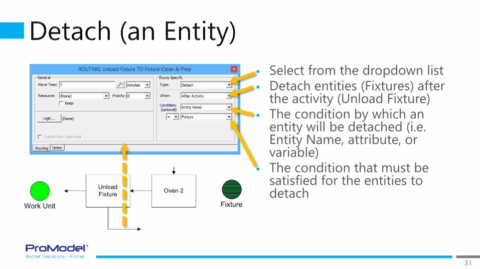
31
Select from the dropdown list Detach entities (Fixtures) after
the activity (Unload Fixture) The condition by which an
entity will be detached (i.e. Entity Name, attribute, or variable)
The condition that must be satisfied for the entities to detach

32
Creates one or more new Entities before or after the Creator Entity completes its time and logic.
You must select the name of the Entity as well as the quantity to be created.
Note that all new created Entities have the same Attribute values as the Creator Entity. This can be useful to reunite Entities later in a model if needed.
Unload at
Dock
Inventory
Create
Routing for
Main Entity
(Optional)
Routing for
Main Entity
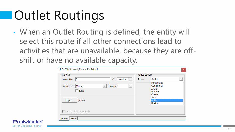
33
When an Outlet Routing is defined, the entity will
select this route if all other connections lead to
activities that are unavailable, because they are off-
shift or have no available capacity.
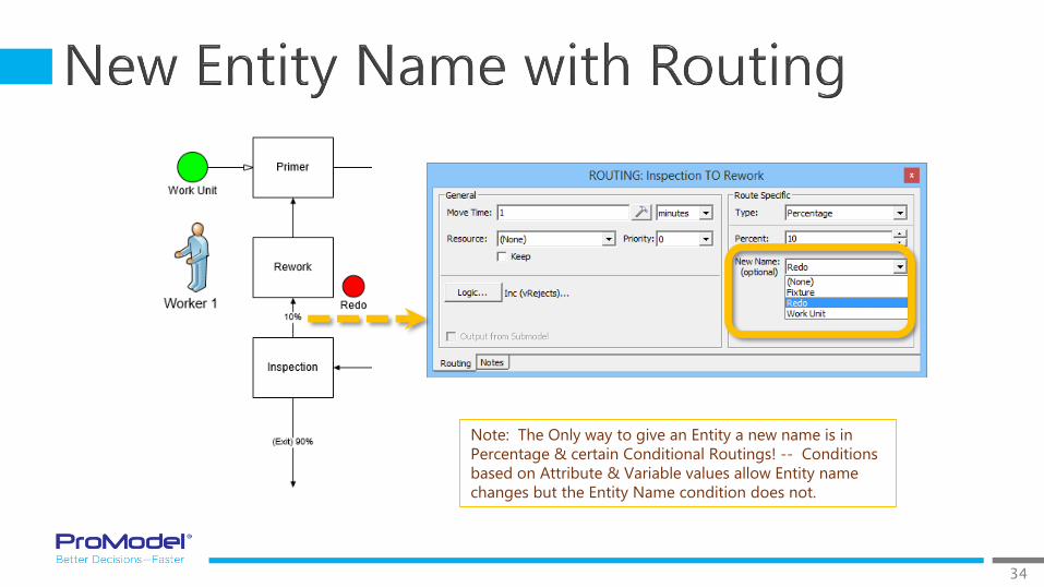
34
Note: The Only way to give an Entity a new name is in
Percentage & certain Conditional Routings! -- Conditions
based on Attribute & Variable values allow Entity name
changes but the Entity Name condition does not.
35
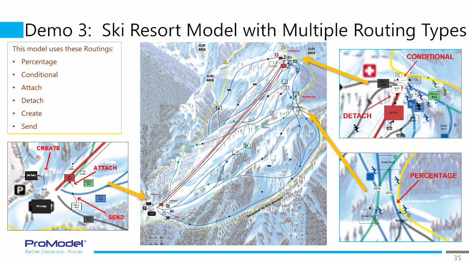
This model uses these Routings:
• Percentage
• Conditional
• Attach
• Detach
• Create
• Send
36
1/2017 Version 9.3PCS Refresher Training Webinar
For Software Version: 9.3Copyright © 2017 ProModel Corporation
556 E Technology WayOrem, UT 84097
801-223-4600
This publication may not be reproduced in whole or in part in any form or by any means, electronic or mechanical, including photocopying, recording, or otherwise, without prior written permission of ProModel Corporation. ProModel and MedModel are registered trademarks of ProModel Corporation.
37
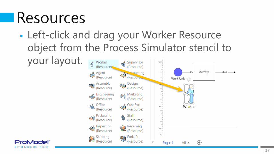
Left-click and drag your Worker Resource
object from the Process Simulator stencil to
your layout.

38
To Use a Resource for an Activity: - Select the desired
resource from the drop-down list.
Note that you must have first placed a resource on the
screen in order for it to appear as an option in the drop-
down list.

39
When we need a Resource, we have been specifying
it by name in the Resource drop-down list.
If we need a Resource for multiple steps there are
additional ways we can more precisely control when
we capture and release Resources:◦ Keep (checkbox)
◦ Get (in Logic)
◦ Free (in Logic)

40
If we select the Keep checkbox in an Activity or Routing dialog, the selected Resource will stay with the Entity for subsequent process steps.
At some downstream step, the Entity MUST release the Resource, by one of two methods:
1. Select again the name of the resource
in the drop down but without
checking the “Keep” option.
2. Use a Free statement in Activity or
Routing Logic.
For example (in the Paint Line model) If I used the Keep
option for Worker 2 at the Rework Activity, the Entity
could subsequently use Worker 2 at Primer without the
Keep option and this would use Worker 2 for the Primer
time and Free the Resource when the Primer processing
was complete.
41
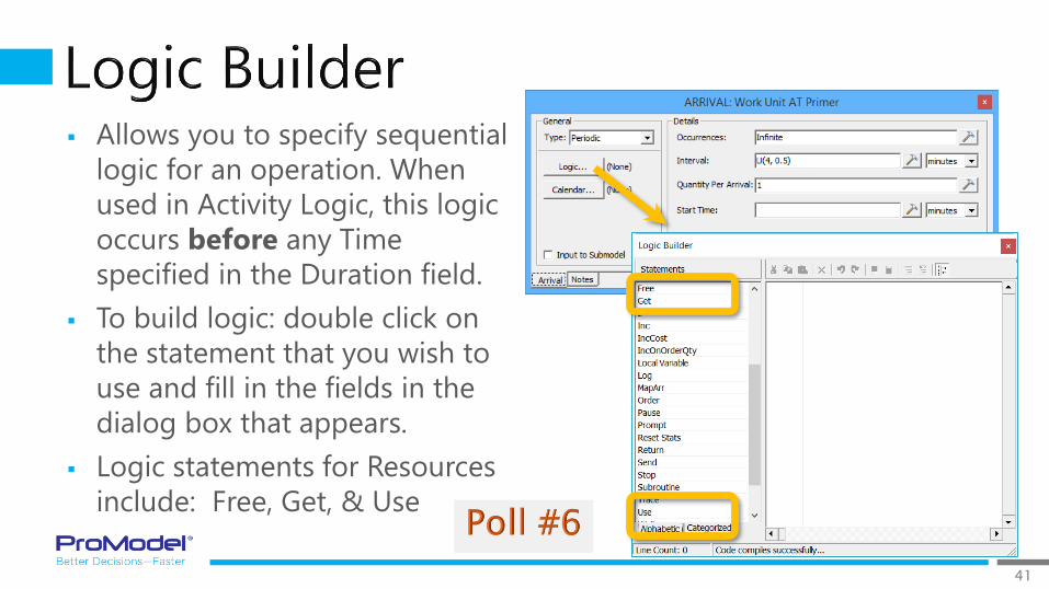
Allows you to specify sequential
logic for an operation. When
used in Activity Logic, this logic
occurs before any Time
specified in the Duration field.
To build logic: double click on
the statement that you wish to
use and fill in the fields in the
dialog box that appears.
Logic statements for Resources
include: Free, Get, & Use
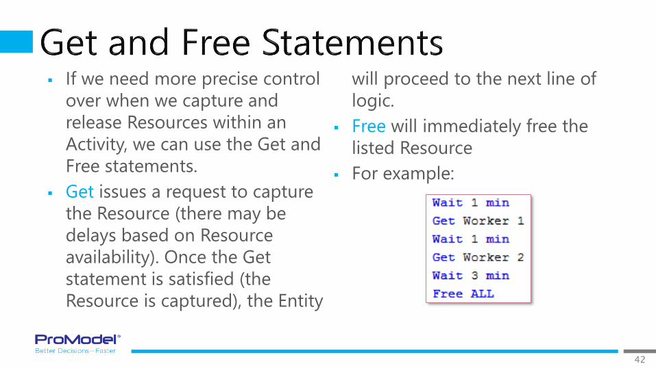
42
If we need more precise control
over when we capture and
release Resources within an
Activity, we can use the Get and
Free statements.
Get issues a request to capture
the Resource (there may be
delays based on Resource
availability). Once the Get
statement is satisfied (the
Resource is captured), the Entity
will proceed to the next line of
logic.
Free will immediately free the
listed Resource
For example:
43
44
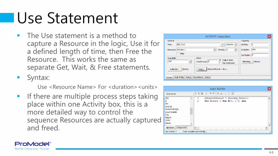
The Use statement is a method to capture a Resource in the logic, Use it for a defined length of time, then Free the Resource. This works the same as separate Get, Wait, & Free statements.
Syntax:
Use <Resource Name> For <duration><units>
If there are multiple process steps taking place within one Activity box, this is a more detailed way to control the sequence Resources are actually captured and freed.
45
46

47
1/2017 Version 9.3PCS Refresher Training Webinar
For Software Version: 9.3Copyright © 2017 ProModel Corporation
556 E Technology WayOrem, UT 84097
801-223-4600
This publication may not be reproduced in whole or in part in any form or by any means, electronic or mechanical, including photocopying, recording, or otherwise, without prior written permission of ProModel Corporation. ProModel and MedModel are registered trademarks of ProModel Corporation.
48
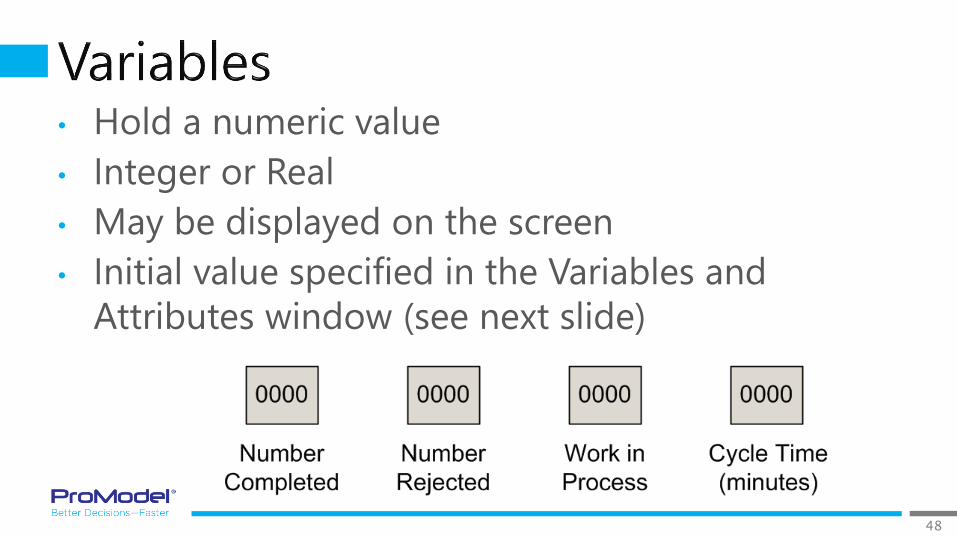
• Hold a numeric value
• Integer or Real
• May be displayed on the screen
• Initial value specified in the Variables and
Attributes window (see next slide)
49
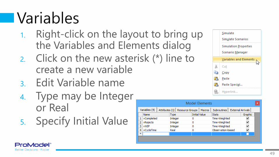
1. Right-click on the layout to bring up the Variables and Elements dialog
2. Click on the new asterisk (*) line to create a new variable
3. Edit Variable name
4. Type may be Integer or Real
5. Specify Initial Value
50
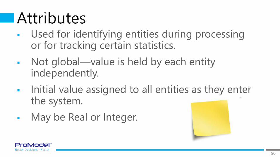
Used for identifying entities during processing or for tracking certain statistics.
Not global—value is held by each entity independently.
Initial value assigned to all entities as they enter the system.
May be Real or Integer.
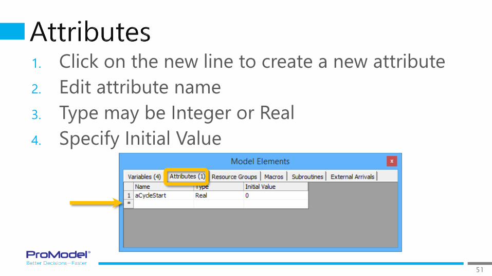
51
1. Click on the new line to create a new attribute
2. Edit attribute name
3. Type may be Integer or Real
4. Specify Initial Value

52
A Macro is an element which can represent a number or a distribution that might be used repetitively throughout your model.
Macros can be used as parameters in the Scenario Manager for scenario analysis.
The Macros table can be found in the Model Elements window, along with Variables and Attributes.
Define the Macro (in the Macros table) and then enter the Macro in Activity Properties or logic, for example.
When you want to change a Macro value, do so in the Macros table or, if it’s a temporary change, you can modify it in the Scenario Manager.
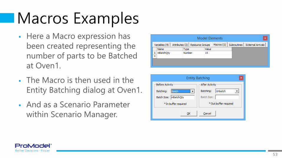
53
Here a Macro expression has
been created representing the
number of parts to be Batched
at Oven1.
The Macro is then used in the
Entity Batching dialog at Oven1.
And as a Scenario Parameter
within Scenario Manager.
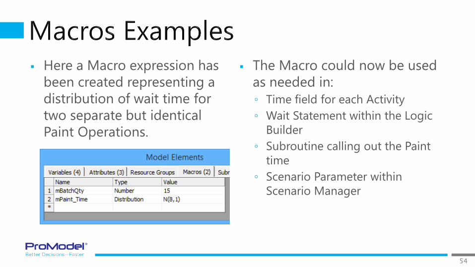
54
Here a Macro expression has
been created representing a
distribution of wait time for
two separate but identical
Paint Operations.
The Macro could now be used
as needed in:
◦ Time field for each Activity
◦ Wait Statement within the Logic
Builder
◦ Subroutine calling out the Paint
time
◦ Scenario Parameter within
Scenario Manager

55
Expression Definition Use When Notes
Attribute Integer or
Real
number
• Entity characteristic determines
action or route
• Needed along with a Variable to
track items
• Not Global; they are
independent to each Entity
• No Output Viewer Stats!
• Exist only during model run
Macro Number or
Distribution
• Value is repeated multiple
places in model
• Needed for Scenario parameter
• Want a single table to edit many
expressions used in logic
• Global to entire model
• No Output Viewer Stats!
• Exist only during model run
• Value cannot be changed
after model run begins!
Variable Integer or
Real
number
• Counting items
• Needed to trigger action
• Value needs to change during
model run
• Global to entire model
• Yes, Output Viewer Stats!
• Can be displayed onscreen
56
57
1/2017 Version 9.3PCS Refresher Training Webinar
For Software Version: 9.3Copyright © 2017 ProModel Corporation
556 E Technology WayOrem, UT 84097
801-223-4600
This publication may not be reproduced in whole or in part in any form or by any means, electronic or mechanical, including photocopying, recording, or otherwise, without prior written permission of ProModel Corporation. ProModel and MedModel are registered trademarks of ProModel Corporation.

58
A data file is generated every time a model runs
The OV links to that file allowing data mining
Use the OV to view different slices of data and examine the process model in detail
Custom charts & tables can be built and saved so they populate with new data after each run
TIP: Always determine some key process metrics early in a model project so you can compare output results later from different Scenarios

59
No Results here is OK if Model does Not have any Single Capacity Activities!

60
Summary – Tables & Column Charts
Utilization – Activities & Resources
State – Entities, Activities, & Resources
Time Series – Data over the model run
61
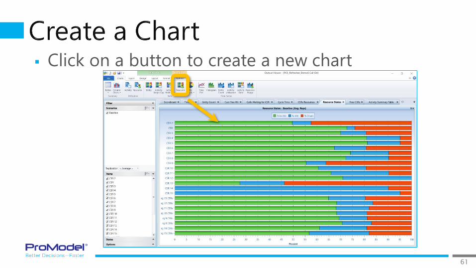
Click on a button to create a new chart

62

63
*Key Output Results you should Always analyze include:
• Throughput (i.e., Entity Exits)
• Cycle/Lead Time (process beginning to end)
• Work in Process (WIP)
• Activity & Resource Utilization

64
1/2017 Version 9.3PCS Refresher Training Webinar
For Software Version: 9.3Copyright © 2017 ProModel Corporation
556 E Technology WayOrem, UT 84097
801-223-4600
This publication may not be reproduced in whole or in part in any form or by any means, electronic or mechanical, including photocopying, recording, or otherwise, without prior written permission of ProModel Corporation. ProModel and MedModel are registered trademarks of ProModel Corporation.
65
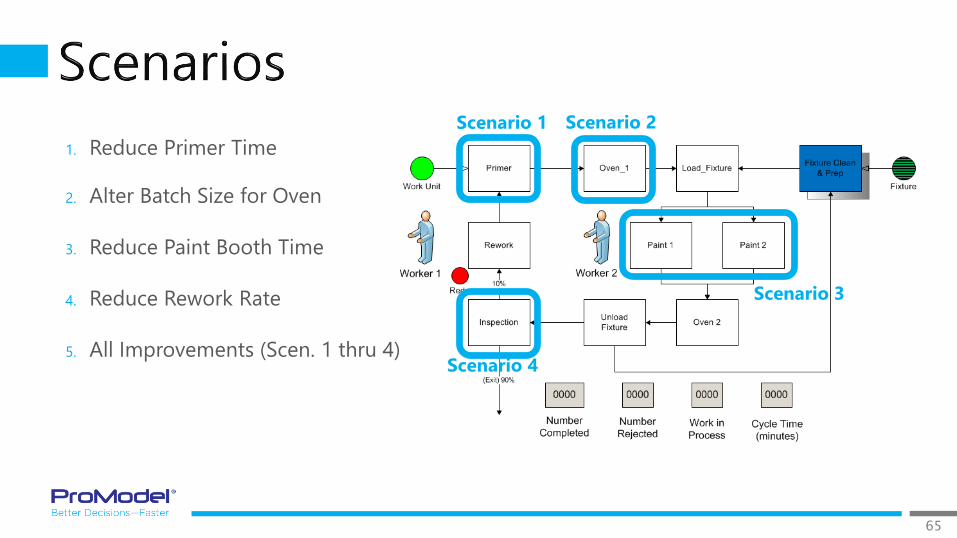
1. Reduce Primer Time
2. Alter Batch Size for Oven
3. Reduce Paint Booth Time
4. Reduce Rework Rate
5. All Improvements (Scen. 1 thru 4)
Scenario 1 Scenario 2
Scenario 3
Scenario 4

66
Scenario Manager allows you to define the parameters
that can be changed, then create Scenarios from those
Parameters.
Step 1. Click “Add Parameter” to
create the list of parameters for experimentation.

67
Select each factor that
you will be varying for
experimentation.
As the parameter is
added, it appears in the
Parameters column and
default values appear in
the Baseline scenario in
Scenario Manager
68
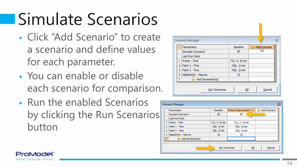
Click “Add Scenario” to create
a scenario and define values
for each parameter.
You can enable or disable
each scenario for comparison.
Run the enabled Scenarios
by clicking the Run Scenarios
button

69
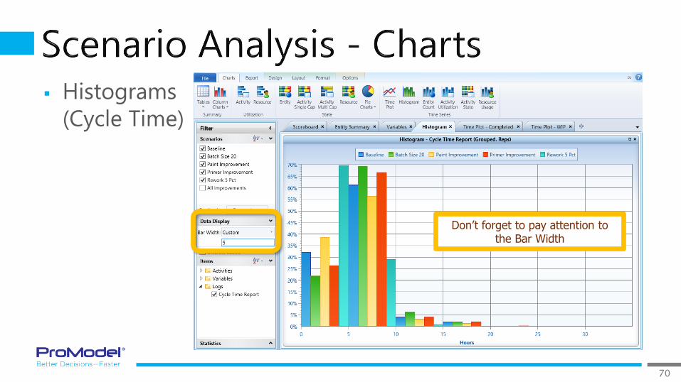
70
Histograms
(Cycle Time)
Don’t forget to pay attention to the Bar Width

71
72
1/2017 Version 9.3PCS Refresher Training Webinar
For Software Version: 9.3Copyright © 2017 ProModel Corporation
556 E Technology WayOrem, UT 84097
801-223-4600
This publication may not be reproduced in whole or in part in any form or by any means, electronic or mechanical, including photocopying, recording, or otherwise, without prior written permission of ProModel Corporation. ProModel and MedModel are registered trademarks of ProModel Corporation.

73
Sharing or archiving models is easy.
Select “Create” from the Packaging area of the Process Simulator Ribbon bar.
This prompts you for a name for your model “Package.”
A model package is saved with a .pcspkg extension and combines: the .vsd file, .pmcal
files, the .pmov file, and any other associated files.
This .pcspkg file can then be copied or emailed to others. They can run the model by
double clicking on the file name or “Install Package.”

74
An array is a matrix of values Each cell works like a variable A reference to a cell in an array
can be used anywhere a variable can be used
Refer to an array value by specifying the value’s row & column cell address, for example, the value 18 above in row 2 and column 3 has a cell address of [2,3]
Cell [1,1] Cell [1,2] Cell [1,3] Cell [1,4]
Cell [2,1] Cell [2,2] Cell [2,3] Cell [2,4]
Cell [3,1] Cell [3,2] Cell [3,3] Cell [3,4]
10 15 15 20
12 15 18 25
15 15 10 10
Note: Arrays are not available in the Standard
version of PCS; Arrays are only available in PCS PRO.

75
Name and define in the Arrays Tab
Name of
the Array
Row and Column
Dimensions
Allowed types:
Integer, Real, or Expression
Clear (re-import)
or Keep array data
between replications
Note: Arrays can be created by Importing directly from
Excel files! Arrays can also be Exported to Excel files!

76

77

78
Thanks for attending this PCS Refresher simulation
course! We hope it was helpful.
An online, self-paced, step-by-step PCS training course
is also available. For more information, contact the
ProModel Sales Director that works with your company.
Remember, help is only an email or phone call away.
Good luck and happy modeling!
Technical Support
888-776-6633
6 am - 6 pm M-F, Mountain Time