Embed Size (px)
Citation preview
Review of the use of Seepage Collars in Small Dams
September 2006
Environment bay of Plenty
Final

Damwatch Services Ltd Job DW526 – Final Issue
Approved for issue: ........................................................................................... Murray Gillon Date 28/09/2006
Review of the use of Seepage Collars in Small Dams
September 2006
Environment Bay of Plenty
Final
Environment Bay of Plenty Review of the use of Seepage Collars in Small Dams Sep-06
DamWatch Services Ltd i Job DW526 – Final Issue
EXECUTIVE SUMMARY During recent litigation, arising from the piping failure of an earth embankment, the efficacy of
seepage collars was challenged by the defence. As a result Environment Bay of Plenty (EBOP)
decided to review the use of seepage collars within it’s standard guidelines and proposed
Regional Water and Land Plan.
From the review and evaluation of the use of seepage collars in small dams it was identified that
current EBOP Guidelines did not reflect current international practice. An EBOP Workshop
identified the requirement to revise the EBOP Guidelines with the preferred option to adopt
Filter Collars and discontinue Seepage Collars.
The results of this collaborative working have been captured in the EBOP proposed “Schedule
X - Permitted Dam Construction Requirements”
Environment Bay of Plenty Review of the use of Seepage Collars in Small Dams Sep-06
DamWatch Services Ltd ii Job DW526 – Final Issue
TABLE OF CONTENTS
EXECUTIVE SUMMARY ...........................................................................................................i 1.0 INTRODUCTION.............................................................................................................. 1 2.0 FAILURE MECHANISMS ASSOCIATED WITH CONDUITS........................................... 2 3.0 CURRENT PRACTICE..................................................................................................... 4 4.0 EBOP GUIDELINES......................................................................................................... 7 5.0 SEEPAGE COLLAR WORKSHOP AND FOLLOW UP.................................................... 9 6.0 SUMMARY ..................................................................................................................... 13 7.0 REFERENCES............................................................................................................... 14 APPENDICES APPENDIX A: Sketch of Schedule X Embankment Components. APPENDIX B: Proposed “Schedule X – Permitted Dam Construction Requirements” as edited by Britton Consultants Ltd on behalf of EBOP.
Environment Bay of Plenty Review of the use of Seepage Collars in Small Dams Sep-06
DamWatch Services Ltd 1 Job DW526 – Final Issue
1.0 INTRODUCTION
During recent litigation, arising from the piping failure of an earth embankment, the efficacy of
seepage collars was challenged by the defence. As a result Environment Bay of Plenty (EBOP)
decided to review the use of seepage collars within it’s standard guidelines and proposed
Regional Water and Land Plan.
At the request of EBOP Damwatch have undertaken a review of the use of seepage collars
(sometimes refered to as anti-seepage or cut-off collars) in small dams, including:
• Investigating the current range of practice for preventing piping failure along conduits
through small earth dams,
• Comparison of EBOP Guidelines with current practice,
• Evaluation of the adequacy of EBOP guidelines,
• Running a Seepage Collar Workshop with EBOP stakeholders.
The Seepage Collar Workshop was held at EBOP’s Whakatane Office on 1st August 2006 to
debrief EBOP on the review findings, understand EBOP’s perspective and formulate EBOP’s
requirement for guideline revision. Following the workshop Damwatch also provided comment
on the EBOP’s proposed “Schedule X - Permitted Dam Construction Requirements” as
referenced by EBOP Rule 46 and 47.
This report summarises the findings of the reviews undertaken and the outcome of the Seepage
Collar Workshop and collaborative workings.
This review has not considered the selection and use of materials within conduit construction,
conduit joint separation or leakage, and/or the effects differential settlement as may occur within
the embankment above the conduit. Poor design or construction of these elements may equally
result in failures.
Environment Bay of Plenty Review of the use of Seepage Collars in Small Dams Sep-06
DamWatch Services Ltd 2 Job DW526 – Final Issue
2.0 FAILURE MECHANISMS ASSOCIATED WITH CONDUITS
2.1 Failure Mechanisms Three basic failure mechanisms can be associated with conduits:
• Piping Into the Conduit (i.e. failure of a non-pressurised conduit)
• Flow Out Of the Conduit (i.e. failure of a pressurised conduit)
• Piping Along the Conduit (whereby the conduit remains intact)
Piping Into the Conduit can occur where there is collapse of the conduit (i.e. insufficient conduit
material strength), opening of conduit joints (due to deformation and/or poor construction
practice) or damage of the conduit during construction (e.g. excessive compaction damaging
conduit.)
Flow Out Of the Conduit can occur when there is a rupture of the conduit (i.e. insufficient
conduit material strength, particularly joints), opening of joints (due to deformation of poor
construction practice) or damage of the conduit during construction. Flow out of the conduit can
lead to an increase in seepage causing piping failure and/or saturation of embankment fill
causing slope stability failure.
Piping Along the Conduit can occur due to the presence of a defects (or weakness) along the
length of the conduit. Defects result in preferential pathways along which piping failure can
initiate. The integrity of the conduit itself is not affected.
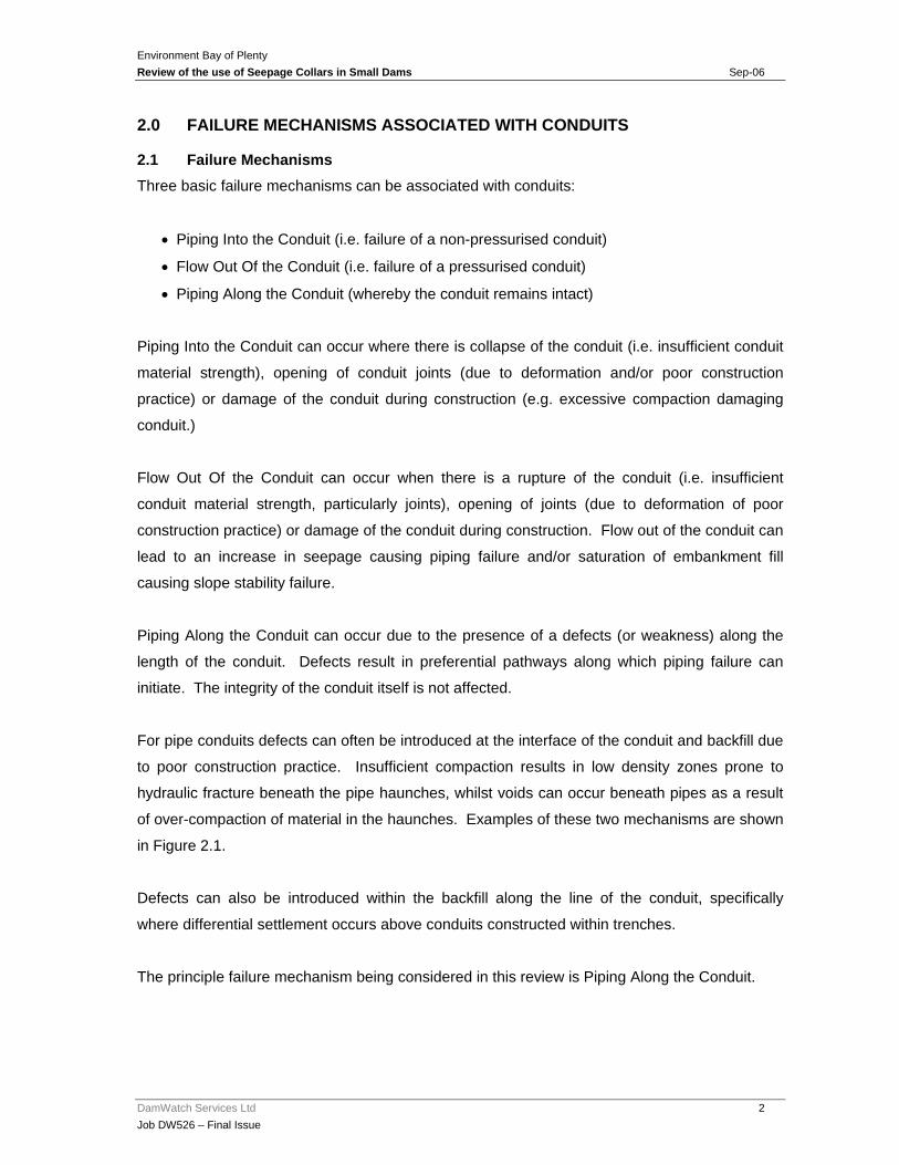
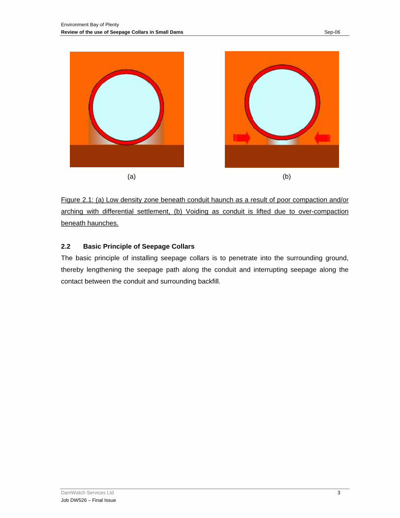
For pipe conduits defects can often be introduced at the interface of the conduit and backfill due
to poor construction practice. Insufficient compaction results in low density zones prone to
hydraulic fracture beneath the pipe haunches, whilst voids can occur beneath pipes as a result
of over-compaction of material in the haunches. Examples of these two mechanisms are shown
in Figure 2.1.
Defects can also be introduced within the backfill along the line of the conduit, specifically
where differential settlement occurs above conduits constructed within trenches.
The principle failure mechanism being considered in this review is Piping Along the Conduit.
Environment Bay of Plenty Review of the use of Seepage Collars in Small Dams Sep-06
DamWatch Services Ltd 3 Job DW526 – Final Issue
(a) (b)
Figure 2.1: (a) Low density zone beneath conduit haunch as a result of poor compaction and/or
arching with differential settlement, (b) Voiding as conduit is lifted due to over-compaction
beneath haunches.
2.2 Basic Principle of Seepage Collars The basic principle of installing seepage collars is to penetrate into the surrounding ground,
thereby lengthening the seepage path along the conduit and interrupting seepage along the
contact between the conduit and surrounding backfill.

Environment Bay of Plenty Review of the use of Seepage Collars in Small Dams Sep-06
DamWatch Services Ltd 4 Job DW526 – Final Issue
3.0 CURRENT PRACTICE
3.1 International Practice It is considered that current international large dam practice has moved away from the use of
Seepage Collars in favour of drainage filters to prevent piping failures (FEMA 2005, Bureau of
Reclamation 1987 and 1992, USACE 1986 and 2004, NRCS 2002 and Fell et al 2005).
Case studies collated and reviewed for this study show that inclusion of seepage collars do not
guarantee against piping failure along conduits. The United States Federal Emergency
Management Agency who have collated case studies conclude that “the theory behind the
development of antiseep collars is flawed, and their continued use may be considered a relic of
conventional design” (FEMA, 2005.) In the 1980’s the use of seepage collars was discontinued
by the U.S. Army Corps of Engineers (USACE) and re-evaluated by the United States Bureau of
Reclamation (USBR). Reasons for discontinuance are included in Table 3.1.
• Seepage Collars impede compaction of soils around the conduit.
• Seepage Collars contribute to differential settlement and create potential
hydraulic fracture zones in the fill.
• Problems associated with conduits were more likely to be caused from internal
erosion mechanisms than from intergranular seepage.
• Design confidence in the capability and reliability of filters to prevent internal
erosion failures has increased.
• Seepage collars can form a foundation discontinuity that could result in
differential settlement and cracking of the conduit.
Table 3.1: Reasons for the discontinuance of Seepage Collars (based on FEMA, 2005.)
That Seepage Collars can result in the introduction of defects along the length of the conduit is
a significant driver for their discontinuance.
Notwithstanding the above there are instances where the allowance for the construction of
seepage collars remains. For example the U.S. Natural Resources Conservation Service
(NRCS) has discontinued the use of seepage collars on new dams unless it is determined that
seepage collars will adequately serve the purpose (NRCS, 2002.) Although NRCS continues to
identify general requirements for seepage collars (included in Table 3.2) there is a requirement
for engineering input.

Environment Bay of Plenty Review of the use of Seepage Collars in Small Dams Sep-06
DamWatch Services Ltd 5 Job DW526 – Final Issue
3.2 Local Practice in New Zealand Local practice in New Zealand continues to detail the installation of seepage collars (e.g.
Auckland Regional Council, Environment Bay of Plenty, Marlborough District Council and
Taranaki Regional Council). The detail provided is variable across local practice, with no single
approach to seepage collar sizing, spacing, positioning or materials. Local guidelines do
however recognise that there are inherent problems associated with the construction of
seepage collars.
A transition from seepage collars to drainage filters is perhaps examplified by the guidelines of
Auckland Region Council (ARC) who include provision for seepage collars and what ammounts,
to a drainage diaphragm. Part 3 of the ARC dam safety guidelines recognises that seepage
collars represent a “classical approach” and that the problems of ensuring adequate compaction
means that seepage collars should not be relied on as the only means of controlling seepage.
The ARC guidelines do consider that seepage collars “are still applicable in many situations”
although no detail is provided.
Collar Detail Collar Spacing Reference
Seepage collars should be made of reinforced concrete generally from 2 to 3 feet high, 12 to 18 inches wide. Such collars increase the length of the percolation path by 20 to 30 percent.
Spacing should be 7 to 10 times the collar height.
USBR. 1987.
Seepage collars shall increase by at least 15 percent the seepage path along the pipe. Seepage collars shall have a watertight connection to the pipe and collar materials shall be compatible with the pipe materials.
Maximum spacing approx. 14 times the minimum projection of the collar measured perpendicular to the pipe but not more than 25 feet or less than 10 feet.
NRCS, 2002.
Seepage collars shall be at least 1m by 1m and 0.1m thick. Backfill should be placed in 0.1m layers, rammed into place.
Seepage Collar should be provided at the conduits half-way point.
Taranaki Regional Council Guidance
Seepage collar diameter and thickness are to be a minimum of three times the pipe diameter, constructed from bentonite or similar.
Seepage Collars should be provided along the upstream half of the pipes length, using at least one collar for dams of less than 2.5m in height, and at least two for higher dams.
Auckland Regional Council Guidance
Vertical Seepage Collar projection should be 1 metre. Reference is made to poured concrete collars.
Collar spacing should be 10 times the vertical projection of each collar.
EBOP Guidance
Table 3.2: Examples of Seepage Collar Specifications.
Environment Bay of Plenty Review of the use of Seepage Collars in Small Dams Sep-06
DamWatch Services Ltd 6 Job DW526 – Final Issue
3.3 Best Technical Practice Current practice is driven by the analysis of failures and caution has to be exercised in the case
of local variations, specifically soils, which may require special consideration. Application of
international practice and/or the local practice of an adjacent region may not always be
appropriate.
Overall technical documentation and case studies supports drainage filters as the best technical
practice against piping failures (e.g: Bureua of Reclaimation 1992 and USACE 2004) and this is
supported in that the basis of filter design is technically sound.
Drainage filters, specifically filter collars, constructed on the line of the conduit act as a drain
and intercept any fines being eroded along the line of the conduit. Continuation of the filter
drain along the length of the conduit downstream from the filter collar is required to ensure
drainage of the filter collar.
Whilst drainage filters represent best technical practice it must be recognised that a poorly
designed and/or badly constructed drainage filter to a conduit may also be susceptable to
failure.

Environment Bay of Plenty Review of the use of Seepage Collars in Small Dams Sep-06
DamWatch Services Ltd 7 Job DW526 – Final Issue
4.0 EBOP GUIDELINES
4.1 Current EBOP Guidelines 4.1.1 General
Currently three standard guidelines are used by Environmental Bay of Plenty’s (EBOP) in the
application of seepage collars in dams. These include:
• Hydrological and Hydraulic Guidelines
• Erosion and Sediment Control Guidelines
• Guidelines for the Design, Construction, Maintenance and Safety of Small Flood Detention
Dams (Draft Version)
In addition EBOP is proposing Regional Water and Land Plan Rules 46, 47 and 47A which will
deal with aspects of small dams. EBOP’s proposal “Schedule X – Permitted Dam Construction
Requirements” associated with these rules is discussed in Section 5.4.
4.1.2 Hydrological and Hydraulic Guidelines
The Hydrological and Hydraulic Guidelines make reference to seepage collars in embankments
and small dams. The guidelines state that practices should include “Use of anti-seep collars on
pipes through the embankment.” (Section 7.4, Item vii)
4.1.3 Erosion and Sediment Control Guidelines
The Erosion and Sediment Control Guidelines refers to “..use of anti-seep collars on all pipes”
(Section 5.1.6.). Design criteria of the anti-seep collars also considers collar spacing of
approximately 10 times the vertical projection of each collar and that the vertical projection of
each collar is 1 metre (Section 5.1.9.) Specification detail is included in Appendix B.
4.1.4 Guidelines for the Design, Construction , Maintenance and Safety of Small Flood
Detention Dams (Draft Version)
The Guidelines for the Design, Construction , Maintenance and Safety of Small Flood Detention
Dams consider; “For service outlet pipe, cut trench in natural ground under the dam whever
possible. Scarify bedding, re-compact, place pipe, fill in 200 lifts and compact with whacker.
Install an anti-seep collar at the midpoint of the dam. Use strong pipe (e.g. HDPE, thick wall
uPVC, concrete), that will withstand construction loads and early settlement loads. Minimum
size 200mm with throttle plate at inlet only if reduced flow required. Install wingwalls at inlet and
outlet.”
Environment Bay of Plenty Review of the use of Seepage Collars in Small Dams Sep-06
DamWatch Services Ltd 8 Job DW526 – Final Issue
4.2 Evaluation of EBOP Guidelines From the evaluation of Seepage Collars in the EBOP Guidelines against current conduit
installation practice it can be concluded that:
• The Guidelines include for the provision of seepage collars
o when this is no longer current international practice.
• The Guidelines include no requirement for drainage filters,
o when this is current international practice.
• Parts of the current Guidelines are so prescriptive that they approach a “standard”,
o which presents a consequence of risk to EBOP.
• In specifying seepage collars the Guidelines reflect practice in some other parts of New
Zealand
o but this does not necessarily constitute best practice.
The EBOP Guidelines do identify elements of good construction practice, which are of
importance in ensuring successful conduit performance, including:
• Providing a cut trench in natural ground, wherever possible,
• Compaction of backfill,
• Use of strong pipe.
The EBOP Guidelines do not provide advice in the type of backfill adjacent to conduits.
Environment Bay of Plenty Review of the use of Seepage Collars in Small Dams Sep-06
DamWatch Services Ltd 9 Job DW526 – Final Issue
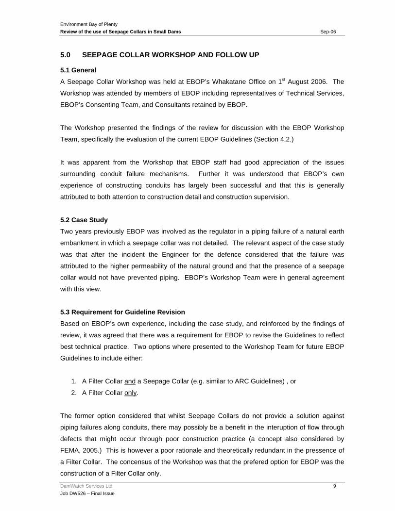
5.0 SEEPAGE COLLAR WORKSHOP AND FOLLOW UP
5.1 General A Seepage Collar Workshop was held at EBOP’s Whakatane Office on 1st August 2006. The
Workshop was attended by members of EBOP including representatives of Technical Services,
EBOP’s Consenting Team, and Consultants retained by EBOP.
The Workshop presented the findings of the review for discussion with the EBOP Workshop
Team, specifically the evaluation of the current EBOP Guidelines (Section 4.2.)
It was apparent from the Workshop that EBOP staff had good appreciation of the issues
surrounding conduit failure mechanisms. Further it was understood that EBOP’s own
experience of constructing conduits has largely been successful and that this is generally
attributed to both attention to construction detail and construction supervision.
5.2 Case Study Two years previously EBOP was involved as the regulator in a piping failure of a natural earth
embankment in which a seepage collar was not detailed. The relevant aspect of the case study
was that after the incident the Engineer for the defence considered that the failure was
attributed to the higher permeability of the natural ground and that the presence of a seepage
collar would not have prevented piping. EBOP’s Workshop Team were in general agreement
with this view.
5.3 Requirement for Guideline Revision Based on EBOP’s own experience, including the case study, and reinforced by the findings of
review, it was agreed that there was a requirement for EBOP to revise the Guidelines to reflect
best technical practice. Two options where presented to the Workshop Team for future EBOP
Guidelines to include either:
1. A Filter Collar and a Seepage Collar (e.g. similar to ARC Guidelines) , or
2. A Filter Collar only.
The former option considered that whilst Seepage Collars do not provide a solution against
piping failures along conduits, there may possibly be a benefit in the interuption of flow through
defects that might occur through poor construction practice (a concept also considered by
FEMA, 2005.) This is however a poor rationale and theoretically redundant in the pressence of
a Filter Collar. The concensus of the Workshop was that the prefered option for EBOP was the
construction of a Filter Collar only.
Environment Bay of Plenty Review of the use of Seepage Collars in Small Dams Sep-06
DamWatch Services Ltd 10 Job DW526 – Final Issue
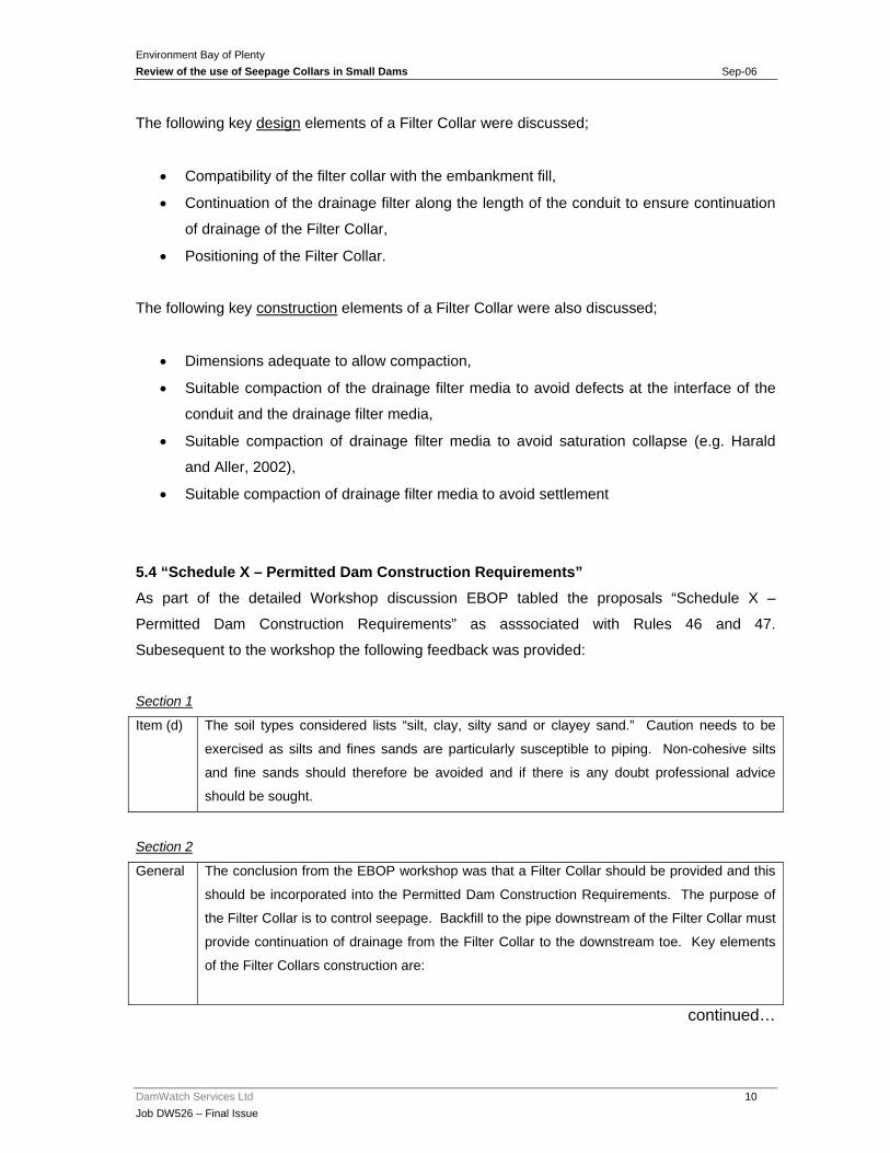
The following key design elements of a Filter Collar were discussed;
• Compatibility of the filter collar with the embankment fill,
• Continuation of the drainage filter along the length of the conduit to ensure continuation
of drainage of the Filter Collar,
• Positioning of the Filter Collar.
The following key construction elements of a Filter Collar were also discussed;
• Dimensions adequate to allow compaction,
• Suitable compaction of the drainage filter media to avoid defects at the interface of the
conduit and the drainage filter media,
• Suitable compaction of drainage filter media to avoid saturation collapse (e.g. Harald
and Aller, 2002),
• Suitable compaction of drainage filter media to avoid settlement
5.4 “Schedule X – Permitted Dam Construction Requirements” As part of the detailed Workshop discussion EBOP tabled the proposals “Schedule X –
Permitted Dam Construction Requirements” as asssociated with Rules 46 and 47.
Subesequent to the workshop the following feedback was provided:
Section 1
Item (d) The soil types considered lists “silt, clay, silty sand or clayey sand.” Caution needs to be
exercised as silts and fines sands are particularly susceptible to piping. Non-cohesive silts
and fine sands should therefore be avoided and if there is any doubt professional advice
should be sought.
Section 2
General The conclusion from the EBOP workshop was that a Filter Collar should be provided and this
should be incorporated into the Permitted Dam Construction Requirements. The purpose of
the Filter Collar is to control seepage. Backfill to the pipe downstream of the Filter Collar must
provide continuation of drainage from the Filter Collar to the downstream toe. Key elements
of the Filter Collars construction are:
continued…
Environment Bay of Plenty Review of the use of Seepage Collars in Small Dams Sep-06
DamWatch Services Ltd 11 Job DW526 – Final Issue
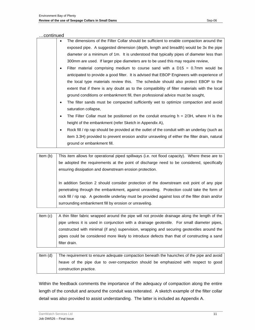
…continued • The dimensions of the Filter Collar should be sufficient to enable compaction around the
exposed pipe. A suggested dimension (depth, length and breadth) would be 3x the pipe
diameter or a minimum of 1m. It is understood that typically pipes of diameter less than
300mm are used. If larger pipe diameters are to be used this may require review,
• Filter material comprising medium to course sand with a D15 = 0.7mm would be
anticipated to provide a good filter. It is advised that EBOP Engineers with experience of
the local type materials review this. The schedule should also protect EBOP to the
extent that if there is any doubt as to the compatibility of filter materials with the local
ground conditions or embankment fill, then professional advice must be sought,
• The filter sands must be compacted sufficiently wet to optimize compaction and avoid
saturation collapse,
• The Filter Collar must be positioned on the conduit ensuring h = 2/3H, where H is the
height of the embankment (refer Sketch in Appendix A),
• Rock fill / rip rap should be provided at the outlet of the conduit with an underlay (such as
item 3.3H) provided to prevent erosion and/or unraveling of either the filter drain, natural
ground or embankment fill.
Item (b) This item allows for operational piped spillways (i.e. not flood capacity). Where these are to
be adopted the requirements at the point of discharge need to be considered, specifically
ensuring dissipation and downstream erosion protection.
In addition Section 2 should consider protection of the downstream exit point of any pipe
penetrating through the embankment, against unraveling. Protection could take the form of
rock fill / rip rap. A geotextile underlay must be provided against loss of the filter drain and/or
surrounding embankment fill by erosion or unraveling.
Item (c) A thin filter fabric wrapped around the pipe will not provide drainage along the length of the
pipe unless it is used in conjunction with a drainage geotextile. For small diameter pipes,
constructed with minimal (if any) supervision, wrapping and securing geotextiles around the
pipes could be considered more likely to introduce defects than that of constructing a sand
filter drain.
Item (d) The requirement to ensure adequate compaction beneath the haunches of the pipe and avoid
heave of the pipe due to over-compaction should be emphasized with respect to good
construction practice.
Within the feedback comments the importance of the adequacy of compaction along the entire
length of the conduit and around the conduit was reiterated. A sketch example of the filter collar
detail was also provided to assist understanding. The latter is included as Appendix A.
Environment Bay of Plenty Review of the use of Seepage Collars in Small Dams Sep-06
DamWatch Services Ltd 12 Job DW526 – Final Issue
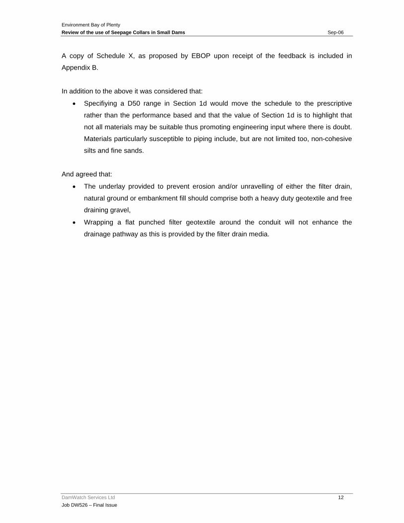
A copy of Schedule X, as proposed by EBOP upon receipt of the feedback is included in
Appendix B.
In addition to the above it was considered that:
• Specifiying a D50 range in Section 1d would move the schedule to the prescriptive
rather than the performance based and that the value of Section 1d is to highlight that
not all materials may be suitable thus promoting engineering input where there is doubt.
Materials particularly susceptible to piping include, but are not limited too, non-cohesive
silts and fine sands.
And agreed that:
• The underlay provided to prevent erosion and/or unravelling of either the filter drain,
natural ground or embankment fill should comprise both a heavy duty geotextile and free
draining gravel,
• Wrapping a flat punched filter geotextile around the conduit will not enhance the
drainage pathway as this is provided by the filter drain media.
Environment Bay of Plenty Review of the use of Seepage Collars in Small Dams Sep-06
DamWatch Services Ltd 13 Job DW526 – Final Issue
6.0 SUMMARY
The review of Seepage Collars in small dams for EBOP identified that the provision of Seepage
Collars in EBOPs Guidelines did not reflect current international practice.
Through the EBOP Workshop and collaborative working it was identified that the was a
requirement to revise the EBOP Guidelines to relfect best technical practice. The concensus of
the Workshop was that the prefered option for EBOP was the construction of a Filter Collar only,
thereby with the discontinuance of Seepage Collars.
Key design and construction elements were discussed at the Workshop and have been carried
through in revisions to the draft “Schedule X – Permitted Dam Construction Requirements.”
Environment Bay of Plenty Review of the use of Seepage Collars in Small Dams Sep-06
DamWatch Services Ltd 14 Job DW526 – Final Issue
7.0 REFERENCES
Auckland Regional Council, Dam Safety Guidelines. Part 2: Guidelines for the building of minimal hazard dams.
Auckland Regional Council, Dam Safety Guidelines. Part 3: Performance guidelines for low, significant and high hazard dams.
Bureau of Reclamation 1992. Embankment Dams – Embankment Design. Design Standards no.13, Chapter 2, 1992.
Environment BOP, Guideline 2001/03 Erosion and Sediment Control Guidelines for Land Disturbing Activities.
Environment BOP, Guideline 2001/04 Hydrological and Hydraulic Guidelines.
Environment BOP, Guideline 2005/01 DRAFT Guidelines for the Design, Construction, Maintenance and Safety of Small Flood Detention Dams.
Fell, R., MacGregor, P., Stapledon, D., and Bell, G., 2005. Geotechnical Engineering of Dams. p.912.
FEMA 2005. Conduits through Embankment Dams – Best Practices for Design, Construction, Problem Identification and Evaluation, Inspection, Maintenance, Renovation and Repair. Federal Emergency Management Agency Technical Manual 484.
Environment BOP, Proposed Regional Water and Land Plan Rules 46, 47 and 47A.
Harald, W., Van Aller, P.E., 2002. Filter Diaphragm Design Considerations – A collection of useful design references and design guidelines. Maryland Water Management Administration.
Johnston,T.A., Millmore,J.P., Charles,J.A. and Tedd,P., 1999. An Engineering Guide to the Safety of Embankment Dams in the United Kingdom. BRE.
NRCS, 2002. National Handbook of Construction Practice Code 378 POND. Natural Resources Conservation Service.
NZSOLD, 1997., Guidelines on Inspecting Small Dams.
U.S. Army Corps of Engineers., 2004. General Design and Construction Considerations for Earth and Rock Fill Dams. EM 1110-2-2300, 2004.

Environment Bay of Plenty Review of the use of Seepage Collars in Small Dams Sep-06
DamWatch Services Ltd 15 Job DW526 – Final Issue
APPENDICES

Environment Bay of Plenty Review of the use of Seepage Collars in Small Dams Sep-06
DamWatch Services Ltd 16 Job DW526 – Final Issue
APPENDIX A
Sketch of Schedule X Embankment Components.


Environment Bay of Plenty Review of the use of Seepage Collars in Small Dams Sep-06
DamWatch Services Ltd 17 Job DW526 – Final Issue
APPENDIX B
Proposed “Schedule X – Permitted Dam Construction Requirements” as edited by Britton Consultants Ltd on behalf of EBOP.
JOHN & RIA BROSNAHAN AND OTHERS ENV A 0211/04
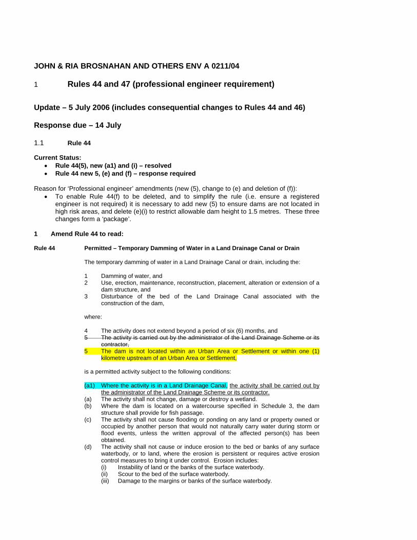
1 Rules 44 and 47 (professional engineer requirement)
Update – 5 July 2006 (includes consequential changes to Rules 44 and 46)
Response due – 14 July 1.1 Rule 44
Current Status: • Rule 44(5), new (a1) and (i) – resolved • Rule 44 new 5, (e) and (f) – response required
Reason for ‘Professional engineer’ amendments (new (5), change to (e) and deletion of (f)):
• To enable Rule 44(f) to be deleted, and to simplify the rule (i.e. ensure a registered engineer is not required) it is necessary to add new (5) to ensure dams are not located in high risk areas, and delete (e)(i) to restrict allowable dam height to 1.5 metres. These three changes form a ‘package’.
1 Amend Rule 44 to read:
Rule 44 Permitted – Temporary Damming of Water in a Land Drainage Canal or Drain
The temporary damming of water in a Land Drainage Canal or drain, including the:
1 Damming of water, and 2 Use, erection, maintenance, reconstruction, placement, alteration or extension of a
dam structure, and 3 Disturbance of the bed of the Land Drainage Canal associated with the
construction of the dam, where:
4 The activity does not extend beyond a period of six (6) months, and 5 The activity is carried out by the administrator of the Land Drainage Scheme or its
contractor, 5 The dam is not located within an Urban Area or Settlement or within one (1)
kilometre upstream of an Urban Area or Settlement, is a permitted activity subject to the following conditions:
(a1) Where the activity is in a Land Drainage Canal, the activity shall be carried out by the administrator of the Land Drainage Scheme or its contractor.
(a) The activity shall not change, damage or destroy a wetland. (b) Where the dam is located on a watercourse specified in Schedule 3, the dam
structure shall provide for fish passage. (c) The activity shall not cause flooding or ponding on any land or property owned or
occupied by another person that would not naturally carry water during storm or flood events, unless the written approval of the affected person(s) has been obtained.
(d) The activity shall not cause or induce erosion to the bed or banks of any surface waterbody, or to land, where the erosion is persistent or requires active erosion control measures to bring it under control. Erosion includes: (i) Instability of land or the banks of the surface waterbody. (ii) Scour to the bed of the surface waterbody. (iii) Damage to the margins or banks of the surface waterbody.

(e) The impoundment of water and the dam structure shall comply with either (i) or (ii): (i) The dam shall not impound more than 5,000 m3 water and the lowest point
of the dam crest does not exceed 1.8 metres vertical height relative to the land where the dam is sited as measured from the centre line of the dam structure.
(ii) The dam does not impound more than 10,000 m3 water and the lowest point of the dam crest does not exceed 1.5 metres vertical height relative to the land where the dam is sited as measured from the centre line of the dam structure.
(f) The structure shall be designed by, or under the guidance of, a registered engineer.
(g) The dam shall be designed, constructed and maintained to ensure that its structural integrity is not compromised, and incorporates a spillway with a 10% AEP (1 in 10 return) event flood design standard, and erosion protection devices, to safely return surplus water to land or water where the dam is sited.
(h) The dam shall, at all times, be maintained in a sound condition. (i) The dam structure shall be removed when not in use it is no longer required, or
after six (6) months, whichever is the sooner. Explanation/Intent of Rule
Allows for the damming of land drainage canals and drains, including for the purposes of reducing the shrinkage of peat soils. The rule does not allow for the diversion of water. The activity is unlikely to have more than minor adverse environmental effects.
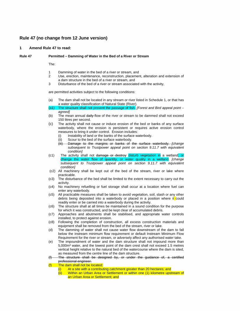
Rule 47 (no change from 12 June version) 1 Amend Rule 47 to read:
Rule 47 Permitted – Damming of Water in the Bed of a River or Stream
The:
1 Damming of water in the bed of a river or stream, and 2 Use, erection, maintenance, reconstruction, placement, alteration and extension of
a dam structure in the bed of a river or stream, and 3 Disturbance of the bed of a river or stream associated with the activity,
are permitted activities subject to the following conditions:
(a) The dam shall not be located in any stream or river listed in Schedule 1, or that has a water quality classification of Natural State (River).
(a1) The structure shall not prevent the passage of fish. [Forest and Bird appeal point – agreed]
(b) The mean annual daily flow of the river or stream to be dammed shall not exceed 150 litres per second.
(c) The activity shall not cause or induce erosion of the bed or banks of any surface waterbody, where the erosion is persistent or requires active erosion control measures to bring it under control. Erosion includes: (i) Instability of land or the banks of the surface waterbody. (ii) Scour to the bed of the surface waterbody. (iii) Damage to the margins or banks of the surface waterbody. [change
subsequent to Trustpower appeal point on section 9.11.7 with equivalent condition]
(c1) The activity shall not damage or destroy disturb vegetation in a wetland; or change the water flow of quantity, or water quality in a wetland. [change subsequent to Trustpower appeal point on section 9.11.7 with equivalent condition]
(c2) All machinery shall be kept out of the bed of the stream, river or lake where practicable.
(c3) The disturbance of the bed shall be limited to the extent necessary to carry out the activity.
(c4) No machinery refuelling or fuel storage shall occur at a location where fuel can enter any waterbody.
(c5) All practicable measures shall be taken to avoid vegetation, soil, slash or any other debris being deposited into a waterbody or placed in a position where it could readily enter or be carried into a waterbody during the activity.
(c6) The structure shall at all times be maintained in a sound condition for the purpose for which it was constructed, and be kept clear of accumulated debris.
(c7) Approaches and abutments shall be stabilised, and appropriate water controls installed, to protect against erosion.
(c8) Following the completion of construction, all excess construction materials and equipment shall be removed from the bed of the stream, river or lake.
(d) The damming of water shall not cause water flow downstream of the dam to fall below the instream minimum flow requirement or default Instream Minimum Flow Requirement for the river or stream, or adversely affect any authorised water take.
(e) The impoundment of water and the dam structure shall not impound more than 5,000m³ water, and the lowest point of the dam crest shall not exceed 1.5 metres vertical height relative to the natural bed of the watercourse where the dam is sited, as measured from the centre line of the dam structure.
(f) The structure shall be designed by, or under the guidance of, a certified professional engineer.
(f) The dam shall not be located: (i) At a site with a contributing catchment greater than 20 hectares; and (ii) Within an Urban Area or Settlement or within one (1) kilometre upstream of
an Urban Area or Settlement; and
(iii) Within 500 metres upstream of an existing dwelling or property boundary, as measured in a straight line.
(f1) The dam shall be constructed in accordance with the Permitted Dam Construction Requirements in Schedule X.
(g) The dam shall be designed, constructed and maintained to ensure that its structural integrity is not compromised, and incorporates a spillway with a 1 in 100 year flood design standard, and erosion protection devices, to safely return surplus water to the natural bed of the river or stream.
(h) All dams constructed after 23 March 2004 shall be registered with Environment Bay of Plenty by forwarding the following information: (i) The location of the dam. (ii) The surface waterbody on which the dam is located. (iii) The size of the dam.
(i) The activity shall not cause or increase flooding or ponding on any land or property owned or occupied by another person that would not naturally carry water during storm or flood events, unless the written approval of the affected person(s) has been obtained. [Minor amendment]
Advisory Note
1 In relation to (d), the community is advised to contact Environment Bay of Plenty for information regarding the instream minimum flow requirement or default instream minimum flow requirement for the river or stream.
2 In relation to condition (a1), Environment Bay of Plenty has information to assist resource users to provide fish passage on dam structures. [Forest and Bird appeal point – agreed]
3 In relation to condition (f), catchment size above a proposed dam site can be determined by measuring catchment dimensions on a NZMS 260 series map, or similar topographical map. [minor addition to clarify application of rule]
Explanation/Intent of Rule
To permit the damming of water in small streams and rivers where the adverse environmental effects are likely to be no more than minor. The rule applies to temporary or permanent damming of water, and does not permit the diversion of water. It is not intended for this rule to apply to instream stormwater treatment ponds.
Consequential change to Rule 46 for consistency with Rule 47 1 Amend Rule 46 to read:
Rule 46 Permitted – Damming of Surface Run-off Water
The damming of water, and associated dam structure, that:
1 Is in an ephemeral flowpath or gully, or 2 Is in an artificial watercourse, or 3 Is run-off from the surface of land, is a permitted activity, subject to the following conditions:
(a) The activity shall not change, damage or destroy a wetland. (b) The activity shall not cause or increase flooding or ponding on any land or property
owned or occupied by another person that would not naturally carry water during storm or flood events, unless the written approval of the affected person(s) has been obtained.
(c) The activity shall not cause or induce erosion to the bed or banks of any surface waterbody, or to land, where the erosion is persistent or requires active erosion control measures to bring it under control. Erosion includes: (i) Instability of land or the banks of the surface waterbody; (ii) Scour to the bed of the surface waterbody; (iii) Damage to the margins or banks of the surface waterbody.
(d) The impoundment of water and the dam structure shall comply with either (i) or (ii) (i) The dam shall not impound more than 5,000 m3 water and the level of the
dam spillway invert does not exceed 2.5 metres vertical height relative to the land where the dam is sited as measured from the centre line of the dam structure (refer to Figure 2B).
(ii) The dam does not impound more than 10,000 m3 water and the level of the dam spillway invert does not exceed 1.5 metres vertical height relative to the land where the dam is sited as measured from the centre line of the dam structure (refer to Figure 2B).
(e) The structure shall be designed by, or under the guidance of, a registered engineer.
(e) The dam shall not be located: (i) At a site with a contributing catchment greater than 20 hectares; and (ii) Within an Urban Area or Settlement or within one (1) kilometre upstream of
an Urban Area or Settlement; and (iii) Within 500 metres upstream of an existing dwelling or property boundary, as
measured in a straight line. (e1) The dam shall be constructed in accordance with the Permitted Dam Construction
Requirements in Schedule X. (f) The dam shall be designed, constructed and maintained to ensure that its
structural integrity is not compromised, and incorporates spillway with a 1 in 100 year flood design standard, and erosion protection devices, to safely return surplus water to land where the dam is sited.
(g) The dam shall, at all times, be maintained in a sound condition. Explanation/Intent of Rule
To allow the minor damming of clean water that is not in the bed of a permanently flowing stream or river, or a lake or wetland. It includes, but is not limited to: • stock water dams, • prevention of peat shrinkage, • coffer dams, • detention dams for erosion control, • dams for the creation of wetland, and
• activities relating to water harvesting. The rule does not apply to earthworks sediment retention ponds, which will be addressed in conjunction with the discharge of sediment-contaminated stormwater in a resource consent under Rule 37, and does not permit the diversion of water. Note that Rule 44A addresses the diversion of stormwater.
A new Rule 46A has been added to the Plan as a result of a Carter Holt Harvey appeal point – this is shown for clarity only and is the subject of a consent order.
Rule 46A Discretionary Restricted – Damming of Surface Run-off Water
The damming of water, and associated dam structure, that:
1 Is in an ephemeral flowpath or gully, or 2 Is in an artificial watercourse, or 3 Is run-off from the surface of land, and is not otherwise permitted by Rule 46 is a discretionary restricted activity, subject to the following condition:
(a) The activity shall not disturb vegetation in a wetland, or change the water flow or quantity, or water quality in a wetland.
Environment Bay of Plenty retains discretion over:
(a) Measures to avoid, remedy or mitigate adverse effects on: (i) Water flows. (ii) Land owned or occupied by another person, including flooding and ponding. (iii) The stability of land. (viii) Houses, assets and other activities downstream of the culvert, which are at
risk of the culvert failure. (b) The structural integrity, safety issues, construction standards. (c) Maintenance of the dam. (d) Measures to avoid or mitigate vegetation, soil, slash, construction material or other
debris being deposited in a surface waterbody, or placed in a position where it could readily enter or be carried into a waterbody.
(e) Monitoring requirements. Explanation/Intent of Rule
To allow the damming of water that is not in the bed of a permanently flowing stream or river, or a lake or wetland and not otherwise permitted by Rule 46. It includes, but is not limited to:
• stock water dams, • prevention of peat shrinkage, • coffer dams, • detention dams for erosion control, • dams for the creation of wetland, and • activities relating to water harvesting.
The rule does not apply to earthworks sediment retention ponds, which will be addressed in conjunction with the discharge of sediment-contaminated stormwater in a resource consent under Rule 37, and does not permit the diversion of water. Rule 44A addresses the diversion of stormwater.
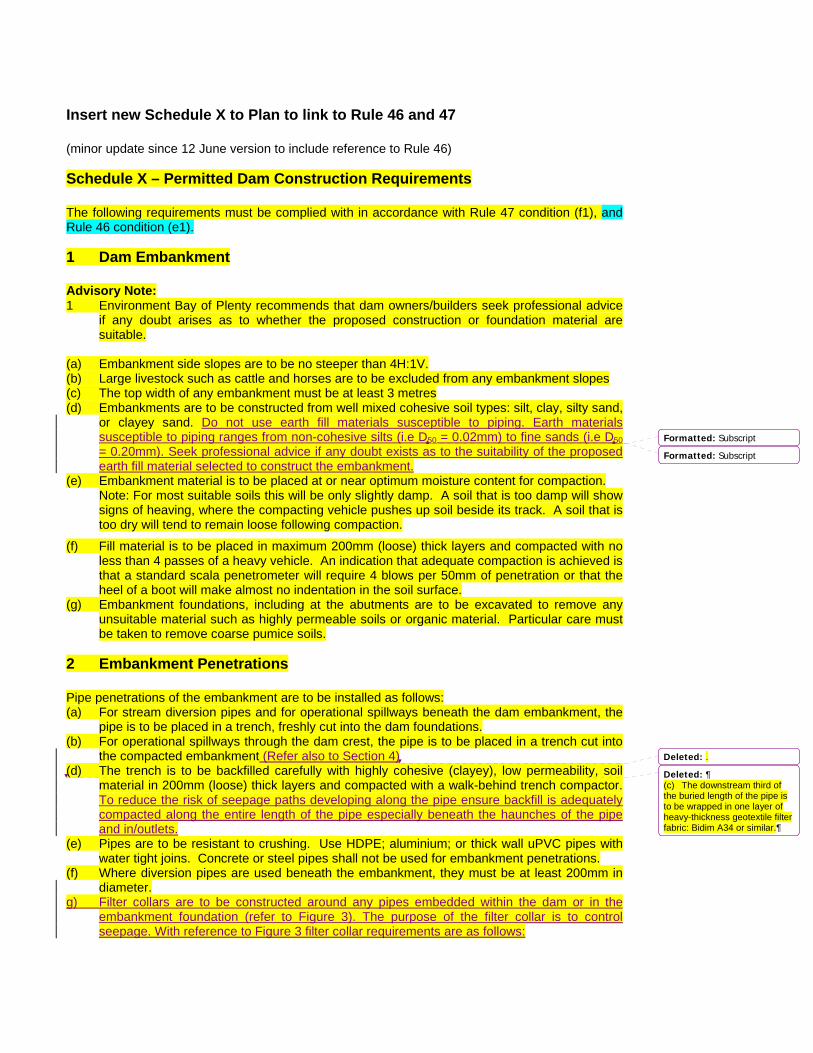
Insert new Schedule X to Plan to link to Rule 46 and 47 (minor update since 12 June version to include reference to Rule 46)
Schedule X – Permitted Dam Construction Requirements The following requirements must be complied with in accordance with Rule 47 condition (f1), and Rule 46 condition (e1).
1 Dam Embankment Advisory Note: 1 Environment Bay of Plenty recommends that dam owners/builders seek professional advice
if any doubt arises as to whether the proposed construction or foundation material are suitable.
(a) Embankment side slopes are to be no steeper than 4H:1V. (b) Large livestock such as cattle and horses are to be excluded from any embankment slopes (c) The top width of any embankment must be at least 3 metres (d) Embankments are to be constructed from well mixed cohesive soil types: silt, clay, silty sand,
or clayey sand. Do not use earth fill materials susceptible to piping. Earth materials susceptible to piping ranges from non-cohesive silts (i.e D50 = 0.02mm) to fine sands (i.e D50 = 0.20mm). Seek professional advice if any doubt exists as to the suitability of the proposed earth fill material selected to construct the embankment.
(e) Embankment material is to be placed at or near optimum moisture content for compaction. Note: For most suitable soils this will be only slightly damp. A soil that is too damp will show signs of heaving, where the compacting vehicle pushes up soil beside its track. A soil that is too dry will tend to remain loose following compaction.
(f) Fill material is to be placed in maximum 200mm (loose) thick layers and compacted with no less than 4 passes of a heavy vehicle. An indication that adequate compaction is achieved is that a standard scala penetrometer will require 4 blows per 50mm of penetration or that the heel of a boot will make almost no indentation in the soil surface.
(g) Embankment foundations, including at the abutments are to be excavated to remove any unsuitable material such as highly permeable soils or organic material. Particular care must be taken to remove coarse pumice soils.
2 Embankment Penetrations
Pipe penetrations of the embankment are to be installed as follows: (a) For stream diversion pipes and for operational spillways beneath the dam embankment, the
pipe is to be placed in a trench, freshly cut into the dam foundations. (b) For operational spillways through the dam crest, the pipe is to be placed in a trench cut into
the compacted embankment (Refer also to Section 4) (d) The trench is to be backfilled carefully with highly cohesive (clayey), low permeability, soil
material in 200mm (loose) thick layers and compacted with a walk-behind trench compactor. To reduce the risk of seepage paths developing along the pipe ensure backfill is adequately compacted along the entire length of the pipe especially beneath the haunches of the pipe and in/outlets.
(e) Pipes are to be resistant to crushing. Use HDPE; aluminium; or thick wall uPVC pipes with water tight joins. Concrete or steel pipes shall not be used for embankment penetrations.
(f) Where diversion pipes are used beneath the embankment, they must be at least 200mm in diameter.
g) Filter collars are to be constructed around any pipes embedded within the dam or in the embankment foundation (refer to Figure 3). The purpose of the filter collar is to control seepage. With reference to Figure 3 filter collar requirements are as follows:
Formatted: Subscript
Formatted: Subscript
Deleted: .
Deleted: ¶(c) The downstream third of the buried length of the pipe is to be wrapped in one layer of heavy-thickness geotextile filter fabric: Bidim A34 or similar.
• The filter collar must be positioned along the conduit ensuring h = 2/3H, where H is the height of the embankment,
• The dimensions of the filter collar should be sufficient to enable compaction around the exposed pipe. A suggested dimension (depth, length and breadth) would be 3x the pipe diameter or a minimum of 1m. If proposed pipe diameters are larger than 300mm then filter collar dimensions may require review,
• Filter material comprising medium to coarse sand with a D15 = 0.7mm is anticipated to provide a good filter. If there is any doubt as to the compatibility of filter materials with the local ground conditions or embankment fill, then professional advice must be sought
• The filter sands must be compacted sufficiently wet to optimize compaction and avoid saturation collapse,
• Backfill to the pipe downstream of the filter collar must provide continuation of drainage from the filter collar to the downstream toe (i.e. the filter drain).
• Rock fill / rip rap should be provided at the outlet of the conduit with an underlay provided to prevent erosion and/or unravelling of either the filter drain, natural ground or embankment fill. The underlay is to comprise 0.2m layer of free draining gravel on a heavy duty geotextile filter fabric, Bidim A34 or similar.
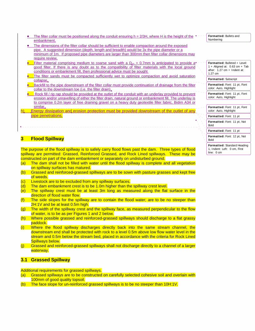
h) Energy dissipation and erosion protection must be provided downstream of the outlet of any pipe penetrations.
3 Flood Spillway The purpose of the flood spillway is to safely carry flood flows past the dam. Three types of flood spillway are permitted: Grassed, Reinforced Grassed, and Rock Lined spillways. These may be constructed on part of the dam embankment or separately on undisturbed ground. (a) The dam shall not be filled with water until the flood spillway is complete and all vegetation
on spillway surfaces has matured. (b) Grassed and reinforced-grassed spillways are to be sown with pasture grasses and kept free
of weeds. (c) Livestock are to be excluded from any spillway surfaces. (d) The dam embankment crest is to be 1.0m higher than the spillway crest level. (e) The spillway crest must be at least 3m long as measured along the flat surface in the
direction of flood water flow. (f) The side slopes for the spillway are to contain the flood water; are to be no steeper than
2H:1V and be at least 0.5m high. (g) The width of the spillway crest and the spillway face, as measured perpendicular to the flow
of water, is to be as per Figures 1 and 2 below. (h) Where possible grassed and reinforced-grassed spillways should discharge to a flat grassy
paddock. (i) Where the flood spillway discharges directly back into the same stream channel, the
downstream end shall be protected with rock to a level 0.5m above low flow water level in the stream and 0.5m below the stream bed, placed in accordance with the criteria for Rock Lined Spillways below.
(j) Grassed and reinforced-grassed spillways shall not discharge directly to a channel of a larger waterway.
3.1 Grassed Spillway Additional requirements for grassed spillways. (a) Grassed spillways are to be constructed on carefully selected cohesive soil and overlain with
100mm of good quality topsoil. (b) The face slope for un-reinforced grassed spillways is to be no steeper than 10H:1V.
Formatted: Bullets andNumbering
Formatted: Bulleted + Level:1 + Aligned at: 0.63 cm + Tabafter: 1.27 cm + Indent at: 1.27 cm
Formatted: Subscript
Formatted: Font: 11 pt, Fontcolor: Auto, Highlight
Formatted: Font: 11 pt, Fontcolor: Auto, Highlight
Formatted: Font: 11 pt, Fontcolor: Auto, Highlight
Formatted: Font: 11 pt
Formatted: Font: 11 pt, NotBold
Formatted: Font: 11 pt
Formatted: Font: 12 pt, NotBold
Formatted: Standard Heading1, Indent: Left: 0 cm, Firstline: 0 cm
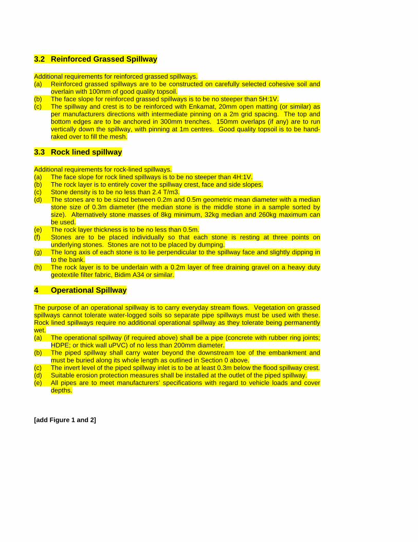
3.2 Reinforced Grassed Spillway Additional requirements for reinforced grassed spillways. (a) Reinforced grassed spillways are to be constructed on carefully selected cohesive soil and
overlain with 100mm of good quality topsoil. (b) The face slope for reinforced grassed spillways is to be no steeper than 5H:1V. (c) The spillway and crest is to be reinforced with Enkamat, 20mm open matting (or similar) as
per manufacturers directions with intermediate pinning on a 2m grid spacing. The top and bottom edges are to be anchored in 300mm trenches. 150mm overlaps (if any) are to run vertically down the spillway, with pinning at 1m centres. Good quality topsoil is to be hand-raked over to fill the mesh.
3.3 Rock lined spillway Additional requirements for rock-lined spillways. (a) The face slope for rock lined spillways is to be no steeper than 4H:1V. (b) The rock layer is to entirely cover the spillway crest, face and side slopes. (c) Stone density is to be no less than 2.4 T/m3. (d) The stones are to be sized between 0.2m and 0.5m geometric mean diameter with a median
stone size of 0.3m diameter (the median stone is the middle stone in a sample sorted by size). Alternatively stone masses of 8kg minimum, 32kg median and 260kg maximum can be used.
(e) The rock layer thickness is to be no less than 0.5m. (f) Stones are to be placed individually so that each stone is resting at three points on
underlying stones. Stones are not to be placed by dumping. (g) The long axis of each stone is to lie perpendicular to the spillway face and slightly dipping in
to the bank. (h) The rock layer is to be underlain with a 0.2m layer of free draining gravel on a heavy duty
geotextile filter fabric, Bidim A34 or similar.
4 Operational Spillway The purpose of an operational spillway is to carry everyday stream flows. Vegetation on grassed spillways cannot tolerate water-logged soils so separate pipe spillways must be used with these. Rock lined spillways require no additional operational spillway as they tolerate being permanently wet. (a) The operational spillway (if required above) shall be a pipe (concrete with rubber ring joints;
HDPE; or thick wall uPVC) of no less than 200mm diameter. (b) The piped spillway shall carry water beyond the downstream toe of the embankment and
must be buried along its whole length as outlined in Section 0 above. (c) The invert level of the piped spillway inlet is to be at least 0.3m below the flood spillway crest. (d) Suitable erosion protection measures shall be installed at the outlet of the piped spillway. (e) All pipes are to meet manufacturers’ specifications with regard to vehicle loads and cover
depths.
[add Figure 1 and 2]