Embed Size (px)
Citation preview

Commercial-In-Confidence
Materials and Engineering ScienceMaterials and Engineering Science
APIA RSC project 2006-004
ANSTO Report R06M132
Review of Strain Based Analysis for Pipelines
Michael Law
30 April 2007
Australian Nuclear Science and Technology Organisation
Private Mail Bag 1, Menai, NSW 2234
REVIEW OF STRAIN BASED ANALYSIS FOR PIPELINES
Page 2 of 58
Review of Strain Based Analysis for Pipelines
DATE ISSUED 30th April 2007
ISSUED TO APIA (2006-004)
REPORT NUMBER JOB NUMBER R06M132 0067m-11-3
AUTHOR
Michael Law
APPROVED BY
Phil Bendeich
REVIEW OF STRAIN BASED ANALYSIS FOR PIPELINES
Page 3 of 58
EXECUTIVE SUMMARY
Pipelines that are subject to ground movement may be safe, despite having exceeded
stress based analysis limits. Strain based analysis may demonstrate the stability and
continued safe operation of a structure under displacement controlled loading when it
has already exceeded stress based limits.
Some simple conservative analytical methods exist to assess the pipeline response to
earth movement; they may mean further analysis is not needed.
In axial tension the failure strain of an un-defected pipe may be below the uniform
strain, the presence of defects reduces the failure strain further. Where large imposed
displacements are expected, reduced acceptable defect sizes may be required.
In bending and compression, failure generally comes about from local buckling. The
critical strain defined in DNV-OS-F101 or API 1111 is recommended as a strain limit
in buckling. In displacement-controlled situations higher strains may be stably
attained, these must be demonstrated by testing and modelling. The presence of girth
welds, defects etc reduces the critical strain. Internal pressure raises the critical strain,
this effect should be ignored if there is a possibility of the pipe being depressurised.
The Australian standard AS2885 allows the use of recognized alternative standards
such as API1111 or DNV-OS-F101 for the design of new pipelines.
More detailed materials characterisation is required for strain-based analysis including
stress-strain curves and the response to strain ageing. As most strains of interest in
strain based analysis are in the axial direction, material properties must be taken in
axial as well as the hoop direction. Coating processes which cause thermal strain
ageing may result in a yield plateau which can reduce the buckling resistance.
Deficiencies in the current state of knowledge that would allow strain based analysis
of pipelines to proceed have been identified. Some of these areas have already been
subject to research, particularly by PRCI. Some recommendations for further research
are given.

REVIEW OF STRAIN BASED ANALYSIS FOR PIPELINES
Page 4 of 58

REVIEW OF STRAIN BASED ANALYSIS FOR PIPELINES
Page 5 of 58
Acknowledgments: The work reported herein was undertaken as a Research Project for the Australian Pipeline
Industry Association (APIA) Research and Standards Committee.
The guidance of the Project Committee, particularly the lead industry adviser Peter Tuft, was
vital at all stages of the project. The members of the Committee were:
Peter Tuft (Industry Advisor) Peter Tuft & Associates
Meng Cheng Agility
Leigh Fletcher MIAB Technology
John Piper OneSteel
Chris Carter Asset Engineering/Agility
Glen Dominish WorleyParsons
Peter Kempster McConnell Dowell
REVIEW OF STRAIN BASED ANALYSIS FOR PIPELINES
Page 6 of 58
Table of Contents 1. Project Summary 7
a. Justification and Reason for Project 7
b. Background 8
2. Strain based analysis 9
a. Displacement control and force control 9
b. Analysis types 10
c. Summary 12
3. Imposed Strain 13
a. Soil Movements 13
b. Installation strains 13
c. Longwall mining subsidence 14
d. Movement transfer to pipeline 15
e. Methods of monitoring ground movement 17
f. Surveying 17
g. Satellite monitoring 17
h. Methods of monitoring pipe movement 18
i. Remediation methods 18
j. Summary 19
4. Pipe resistance to tensile strains 20
a. Plain Pipe 20
b. Welded pipe 21
c. Strain concentration 23
d. HAZ softening 23
e. Summary 24
5. Pipe resistance to compressive strains 25
a. Compression limits 27
b. Effects of girth welds 29
REVIEW OF STRAIN BASED ANALYSIS FOR PIPELINES
Page 7 of 58
c. Effects of imperfections on buckling 30
d. Summary 30
6. Material properties 31
a. Material testing 31
b. YT ratio 31
c. Strain Ageing 32
d. Axial material properties 33
e. Full Scale testing 34
f. Optimising materials 35
g. Summary 36
7. Engineering Critical Assessment methods 37
8. Summary 40
9. Recommendations for further research 42
10. References 44
11. Appendix A - List of relevant reports 48
REVIEW OF STRAIN BASED ANALYSIS FOR PIPELINES
Page 8 of 58
1 PROJECT SUMMARY
Pipelines that are subject to ground movement may be safe, despite having exceeded
stress based analysis limits. Strain based methods assess the strain demands (applied
strain) imposed on a structure as well as the strain capacity (strain limit) of the
structure. Strain based analysis may demonstrate the stability and continued safe
operation of a structure under displacement controlled loading when it has already
exceeded stress based limits.
The objective of this project is to survey the subject and develop a guide to cover
design and assessment of pipelines that may experience high strains in service, and to
make recommendations for the research necessary to achieve these aims.
Traditional conservative methods of designing and assessing a pipeline use stress
based methods. Strain based analysis may offer continued safe operation in pipelines
where the loading is displacement controlled. Strain based analysis is appropriate
when loads may be better described in terms of strain than in terms of stress.
The pipelines covered by this project are limited to welded and buried onshore lines
(this may include aboveground piping to mitigate the effects of large movements).
Typical situations induced by ground movements include tensile, compressive and
bending loads; and combinations of these. Failure modes to be considered include
tensile rupture, compressive wrinkling, compressive buckling, upheaval buckling, and
weld fracture. Guidelines on the limiting strains for each of these failure modes are to
be developed to the extent possible.
1a Justification and Reasons for Project
This project is justified by the very high costs of intervening to keep stresses within
the fully elastic criteria that form the current basis of AS 2885.1. Some pipelines cross
mine subsidence areas in NSW and Queensland, and many other pipelines traverse
sections of steep terrain where slope stability is not assured. There is a high
likelihood, if not certainty, of future occasions where pipelines will be threatened by
ground movement. If a pipeline can be allowed to remain in situ despite ground
movement, with confidence that the strains will remain within acceptable limits, there
REVIEW OF STRAIN BASED ANALYSIS FOR PIPELINES
Page 9 of 58
will be large cost savings and also elimination of the considerable risks involved in
intervention. This project will provide the knowledge base on which to build
confidence in strain based design.
1b Background
Historically, pipelines have been designed to codes that are stress-based. It is possible
to be guided almost entirely through the process by the code documents. This is not
the case for strain based analysis where, at each stage of the process, it is necessary to
identify failure modes and demonstrate that a sound engineering approach has been
adopted and implemented.
Strain based analysis may demonstrate continued safety in pipelines where the loading
is displacement-controlled and it has exceeded stress-based limits. Strain based
analysis is appropriate when some of the loadings may be better described in terms of
strain than in terms of stress.
There are two situations of interest: Firstly where displacement controlled loadings
are anticipated at the design stage, in which case there are considerable analysis and
specification measures available, and secondly where an existing pipeline is exposed
to unexpected movements, in which case there are no options for optimising materials
and welding; and even obtaining information on the as-built pipe can be challenging.
The term Strain Based Analysis has been used rather than Strain Based Design to
widen the scope to the analysis of existing pipelines. Strain based and stress-based
methods should give identical results up to yield, the use of strain based analysis
generally implies that portions of the pipeline may be post-yield.

REVIEW OF STRAIN BASED ANALYSIS FOR PIPELINES
Page 10 of 58
2 STRAIN BASED ANALYSIS
The differences between stress based and strain based analyses only appear above
yield, and are more significant with higher Y/T (yield to tensile ratio) materials.
Above UTS (ultimate tensile strength), an increase in load will lead to collapse, while
an increase in the imposed displacement may lead to further stable plastic straining
(figure 2.1). Below yield, strain based and stress-based analysis return the same
answers. Above yield, strain based analysis is appropriate when the loading is largely
displacement controlled.
Stre
ss
Strain
Force increase ⇒ failure
Displacement increase ⇒ higher strain
Stre
ss
Strain
⇒ failure
Displacement increase ⇒ higher strain
Stre
ss
Strain
Force increase ⇒ failure
Displacement increase ⇒ higher strain
Stre
ss
Strain
⇒ failure
Displacement increase ⇒ higher strain
Figure 2.1 Force and displacement control after maximum load
Most problems require detailed modelling based on the actual stress strain curve,
analytical methods will not return accurate results, but some methods may provide a
conservative (stage 1) assessment which may preclude the need for further analysis. A
“cookbook” style approach is not possible as many steps require detailed material
testing, full scale testing, or finite element analysis.
2a Displacement control and force control
Displacement-controlled loading is a loading that can be reduced to nothing by a
change of shape; by contrast, force-controlled loadings (also known as load-controlled
loading) cannot be reduced with a simple change of shape. Pipeline loadings are a
combination of displacement and force-controlled situations. Pressure is force-
controlled; soil movement is usually displacement-controlled. Pipe laying may result
REVIEW OF STRAIN BASED ANALYSIS FOR PIPELINES
Page 11 of 58
in a combination of displacement and force-controlled situations. Thermal loads and
Poisson’s loads are displacement-controlled. A long length of pipeline exposed to a
displacement controlled loading has an elastic response which may provide a
significant amount of force-controlled loading locally.
There is a complete range of possibilities between displacement-controlled and force-
controlled situations. Strains resulting from displacement-controlled loading can often
be directly calculated. When they occur under force-control, or are intermediate in
type, they may require non-linear elastic-plastic analysis.
“The resistance of a structure to force-controlled and displacement-controlled loads
are governed by the strength and deformation capacity, respectively. Consequently,
the criteria are strength-based for force-controlled limit states and strain based for
displacement-controlled limit states” [Zhou & Glover 2005].
2b Analysis types
Strain based analysis can be used in many of the current design methodologies. These
differ in their treatment of uncertainties in loads and material properties, and the
method of assigning safety factors.
“Strain based design can be applied to a subset of the limit states where displacement-
controlled loads dominate” [Glover and Rothwell, 04]
A number of methods exist which may be used to analyse pipelines. The basis of all
methods is some form of analysis (such as stress-based analysis) with safety factors
which are calculated in various ways to deal with uncertainties in the load or
resistance (figure 2.2 a, b, c). Contrary to common engineering experience, in most
pipeline situations the loads and resistances are well defined. In the situations that
lead to post yield displacement-controlled loadings, the loads are often less well
defined.

REVIEW OF STRAIN BASED ANALYSIS FOR PIPELINES
Page 12 of 58
Strength, stress
Prob
abilit
y
Loadings Resistance or strength
Strength, stress
Prob
abilit
y
Loadings Resistance or strength
Strength, stress
Pro
babi
lity
Loadings Resistance or strength
Strength, stress
Pro
babi
lity
Loadings Resistance or strength
Strength, stress
Prob
abilit
y
Loadings Resistance or strength
?
Strength, stress
Prob
abilit
y
Loadings Resistance or strength
?
Strength, stress
Prob
abilit
y
Loadings Resistance or strength
Strength, stress
Prob
abilit
y
Loadings Resistance or strength
Strength, stress
Pro
babi
lity
Loadings Resistance or strength
Strength, stress
Pro
babi
lity
Loadings Resistance or strength
Strength, stress
Prob
abilit
y
Loadings Resistance or strength
?
Strength, stress
Prob
abilit
y
Loadings Resistance or strength
?
Fig. 2.2 a) Typical distribution of loads and resistances in engineering. When the load
and resistance curves overlap, failure will result.
b) The distribution of loads and resistances in pipelines are tightly defined.
c) Distribution of loadings in displacement-controlled loading may be poorly defined.
Simple methods have a single safety factor which covers these uncertainties and the
consequences of failure while other methods such as Limit State Design (LSD) and its
variants: Reliability-Based Design (RBD) and Load and Resistance Factored Design
(LRFD) deal with these uncertainties by considering the loads, resistances, and
consequences of failure separately. The use of nameplate values such as SMYS is a
form of safety factor.
There are many ways that a structure such as a pipeline could fail and these modes
may be more or less severe; and more or less likely. The factors of safety for these
different modes can be based on these levels of severity and likelihood as well as the
specific parameters that cause the limit state to be reached. DNV-OS-F101 2000 uses
four categories for limit states beyond which the structure no longer satisfies the
requirements: -
• Serviceability limit state (SLS)
• Ultimate limit state (ULS)
• Fatigue limit state (FLS)
• Accidental limit state. (ALS)
Under this process, establishing and calibrating the design criteria leads to two
variants of limit states design methodology: reliability-based design (RBD) and load
and resistance factored design (LRFD).
REVIEW OF STRAIN BASED ANALYSIS FOR PIPELINES
Page 13 of 58
Reliability-based design is a probabilistic design method [ISO/CD 16708 ] where load
effects and structural resistances are regarded as uncertain quantities that are
characterised probabilistically. The basic design criterion in reliability-based design is
to ensure that the failure probability is less than an established acceptable level [Zhou,
Nessim, Zhou 2005]. It is hard to accurately estimate the probability of low
occurrence events such as earthquakes or tidal waves in areas where they are not
common.
LRFD is a deterministic design approach where the factored resistance (e.g. material
properties) should be greater than the factored load (e.g. applied conditions) for each
applicable limit state. The factored resistance is less than or equal to the measured
resistance. Similarly, the factored load is greater than or equal to the calculated load.
There is considerable experience in using limit state methods in offshore engineering,
but there are many details to be considered before using this in onshore displacement
controlled situations.
Many of analytical methods used to predict pipeline resistance to failure by bending
or compression have been formulated within the limit state design framework, using
this methodology should require using partial safety factors from the LRFD
framework.
2c Summary
Strain based analysis is the analysis of structures under displacement controlled
loading, often above yield. There are a complete range of possible loading types
ranging from full force control to full displacement control. Strain based analysis
may be used in the subset of limit design states where displacement controlled loads
dominate. Limit state design is used regularly in the offshore industry and is a
possible route to tackling the more complex analyses needed for strain based design.

REVIEW OF STRAIN BASED ANALYSIS FOR PIPELINES
Page 14 of 58
3 IMPOSED STRAIN
How much strain is imposed on the pipeline depends on the general strains the ground
experiences, and in how much of these then occur in the pipeline. Due to material
property differences and different stress states, there will be different strain limits in
the hoop and axial directions. Where plastic strains are accumulated, the absolute
stains are added together, regardless of sign (compressive or tensile). DNV has special
material requirements where the accumulated plastic strains will be > 2%. This review
does not explicitly addressed cyclic strains; which might come about from installation
techniques used in offshore pipelines (such as reeling), or in high temperature/high
pressure pipelines where low cycle fatigue may be an issue.
3a Soil Movements
Soil movements can come from subsidence, slip, creep, earthquakes, or thaw and frost
heave. Seismic events in themselves have limited effects on pipelines, but can trigger
soil slip, thrust or liquefaction [Honegger 2004, Suzuki & Toyoda 2003]. These
movements will generally be supplied by geologists. The movement that is supplied
as input into an analysis could be from a single event (land slip) or the cumulative
strain over the pipeline life (soil creep).
3b Installation strains
Three standard curvatures have traditionally been used on cold field bending:- 3, 1.5
& 1 degrees per diameter (depending on pipe diameter). These values give 5.2%,
2.6% and 1.7% strain at the outer fiber. Wrinkling may occur and is variable, with
only some pipes from a given heat wrinkling; this is a greater problem with higher
grade, high YT materials. Wrinkles have little effect on burst pressure, but may grow
fatigue cracks through cycling, or may impede pigging and exceed a serviceability
limit.
In Bilston & Murray (1993) the critical wrinkling (which they term buckling) stress in
bending is predicted by:
)1(3 2vEE
Rt longhoop
wrinkle −=σ ____________________3.1
REVIEW OF STRAIN BASED ANALYSIS FOR PIPELINES
Page 15 of 58
The longitudinal stiffness Ehoop was assumed to be the tangent modulus (the local
slope of the stress-strain curve). High Y/T pipe has a lower tangent modulus and
consequently a lower buckling stress. Additionally, higher strength pipe will generally
have a lower wall thickness and lower t/R ratio. This also reduces the wrinkling stress.
This suggests that materials with yield plateaus can buckle very early compared to
materials with smoothly rising stress-strain curves. As the full stress-strain curve is
required for this analysis, the wrinkling strain can also be derived.
Pressure tests on wrinkled pipe showed that wrinkling had little effect on the burst
pressure, and that straining did not accumulate at the wrinkles.
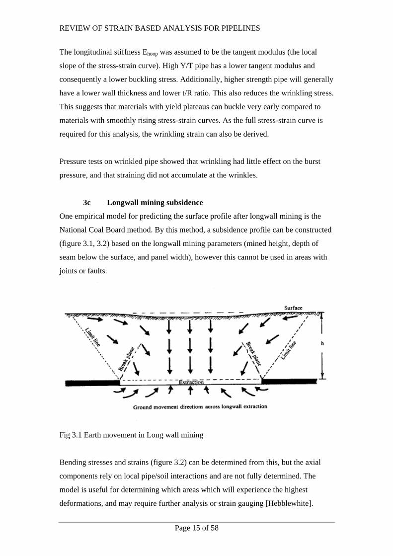
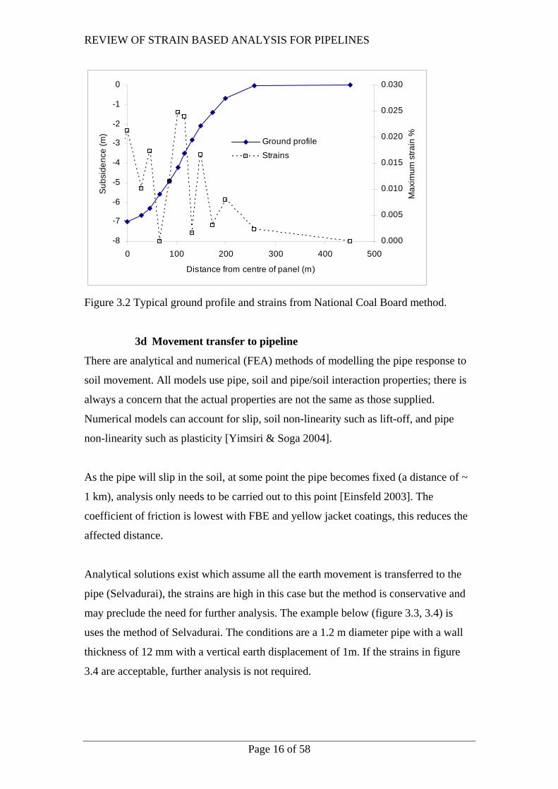
3c Longwall mining subsidence
One empirical model for predicting the surface profile after longwall mining is the
National Coal Board method. By this method, a subsidence profile can be constructed
(figure 3.1, 3.2) based on the longwall mining parameters (mined height, depth of
seam below the surface, and panel width), however this cannot be used in areas with
joints or faults.
Fig 3.1 Earth movement in Long wall mining
Bending stresses and strains (figure 3.2) can be determined from this, but the axial
components rely on local pipe/soil interactions and are not fully determined. The
model is useful for determining which areas which will experience the highest
deformations, and may require further analysis or strain gauging [Hebblewhite].
REVIEW OF STRAIN BASED ANALYSIS FOR PIPELINES
Page 16 of 58
-8
-7
-6
-5
-4
-3
-2
-1
0
0 100 200 300 400 500
Distance from centre of panel (m)
Sub
side
nce
(m)
0.000
0.005
0.010
0.015
0.020
0.025
0.030
Max
imum
stra
in %Ground profile
Strains
Figure 3.2 Typical ground profile and strains from National Coal Board method.
3d Movement transfer to pipeline
There are analytical and numerical (FEA) methods of modelling the pipe response to
soil movement. All models use pipe, soil and pipe/soil interaction properties; there is
always a concern that the actual properties are not the same as those supplied.
Numerical models can account for slip, soil non-linearity such as lift-off, and pipe
non-linearity such as plasticity [Yimsiri & Soga 2004].
As the pipe will slip in the soil, at some point the pipe becomes fixed (a distance of ~
1 km), analysis only needs to be carried out to this point [Einsfeld 2003]. The
coefficient of friction is lowest with FBE and yellow jacket coatings, this reduces the
affected distance.
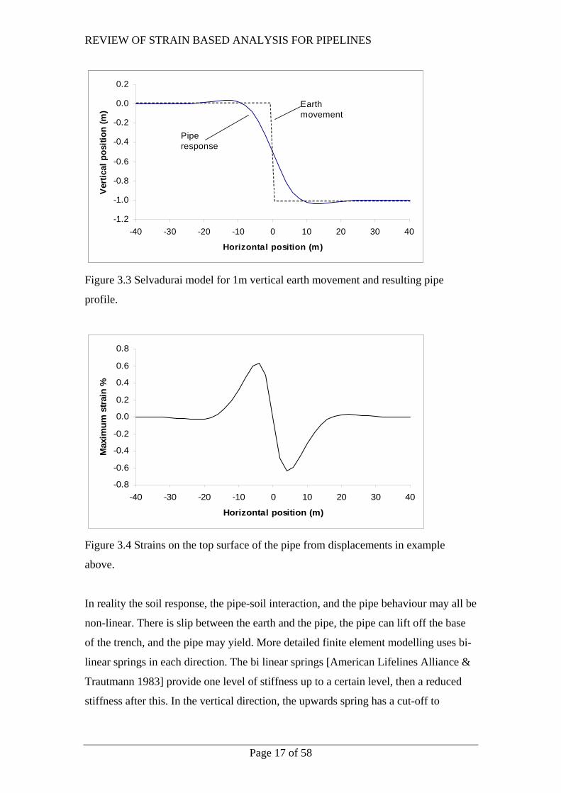
Analytical solutions exist which assume all the earth movement is transferred to the
pipe (Selvadurai), the strains are high in this case but the method is conservative and
may preclude the need for further analysis. The example below (figure 3.3, 3.4) is
uses the method of Selvadurai. The conditions are a 1.2 m diameter pipe with a wall
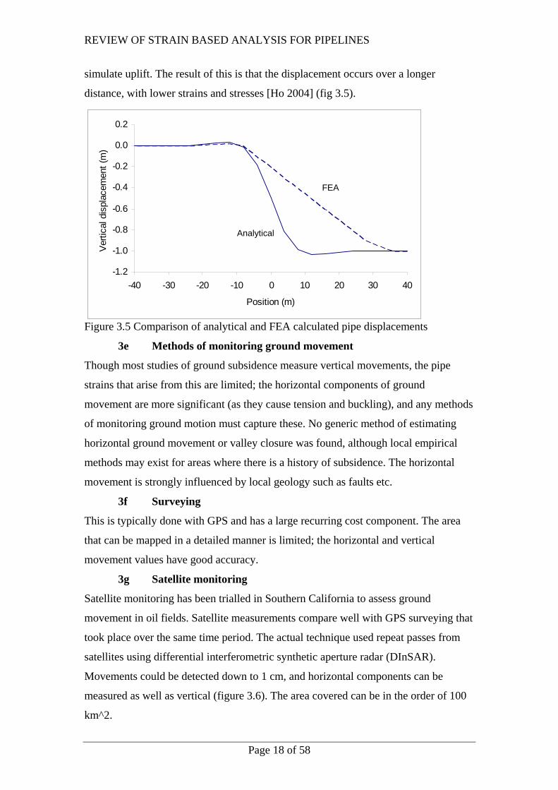
thickness of 12 mm with a vertical earth displacement of 1m. If the strains in figure
3.4 are acceptable, further analysis is not required.
REVIEW OF STRAIN BASED ANALYSIS FOR PIPELINES
Page 17 of 58
-1.2
-1.0
-0.8
-0.6
-0.4
-0.2
0.0
0.2
-40 -30 -20 -10 0 10 20 30 40
Horizontal position (m)
Ver
tical
pos
ition
(m)
Earth movement
Pipe response
-1.2
-1.0
-0.8
-0.6
-0.4
-0.2
0.0
0.2
-40 -30 -20 -10 0 10 20 30 40
Horizontal position (m)
Ver
tical
pos
ition
(m)
Earth movement
Pipe response
Figure 3.3 Selvadurai model for 1m vertical earth movement and resulting pipe
profile.
-0.8
-0.6
-0.4
-0.2
0.0
0.2
0.4
0.6
0.8
-40 -30 -20 -10 0 10 20 30 40
Horizontal position (m)
Max
imum
stra
in %
Figure 3.4 Strains on the top surface of the pipe from displacements in example
above.
In reality the soil response, the pipe-soil interaction, and the pipe behaviour may all be
non-linear. There is slip between the earth and the pipe, the pipe can lift off the base
of the trench, and the pipe may yield. More detailed finite element modelling uses bi-
linear springs in each direction. The bi linear springs [American Lifelines Alliance &
Trautmann 1983] provide one level of stiffness up to a certain level, then a reduced
stiffness after this. In the vertical direction, the upwards spring has a cut-off to
REVIEW OF STRAIN BASED ANALYSIS FOR PIPELINES
Page 18 of 58
simulate uplift. The result of this is that the displacement occurs over a longer
distance, with lower strains and stresses [Ho 2004] (fig 3.5).
-1.2
-1.0
-0.8
-0.6
-0.4
-0.2
0.0
0.2
-40 -30 -20 -10 0 10 20 30 40
Position (m)
Verti
cal d
ispl
acem
ent (
m)
Analytical
FEA
-1.2
-1.0
-0.8
-0.6
-0.4
-0.2
0.0
0.2
-40 -30 -20 -10 0 10 20 30 40
Position (m)
Verti
cal d
ispl
acem
ent (
m)
Analytical
FEA
Figure 3.5 Comparison of analytical and FEA calculated pipe displacements
3e Methods of monitoring ground movement
Though most studies of ground subsidence measure vertical movements, the pipe
strains that arise from this are limited; the horizontal components of ground
movement are more significant (as they cause tension and buckling), and any methods
of monitoring ground motion must capture these. No generic method of estimating
horizontal ground movement or valley closure was found, although local empirical
methods may exist for areas where there is a history of subsidence. The horizontal
movement is strongly influenced by local geology such as faults etc.
3f Surveying
This is typically done with GPS and has a large recurring cost component. The area
that can be mapped in a detailed manner is limited; the horizontal and vertical
movement values have good accuracy.
3g Satellite monitoring
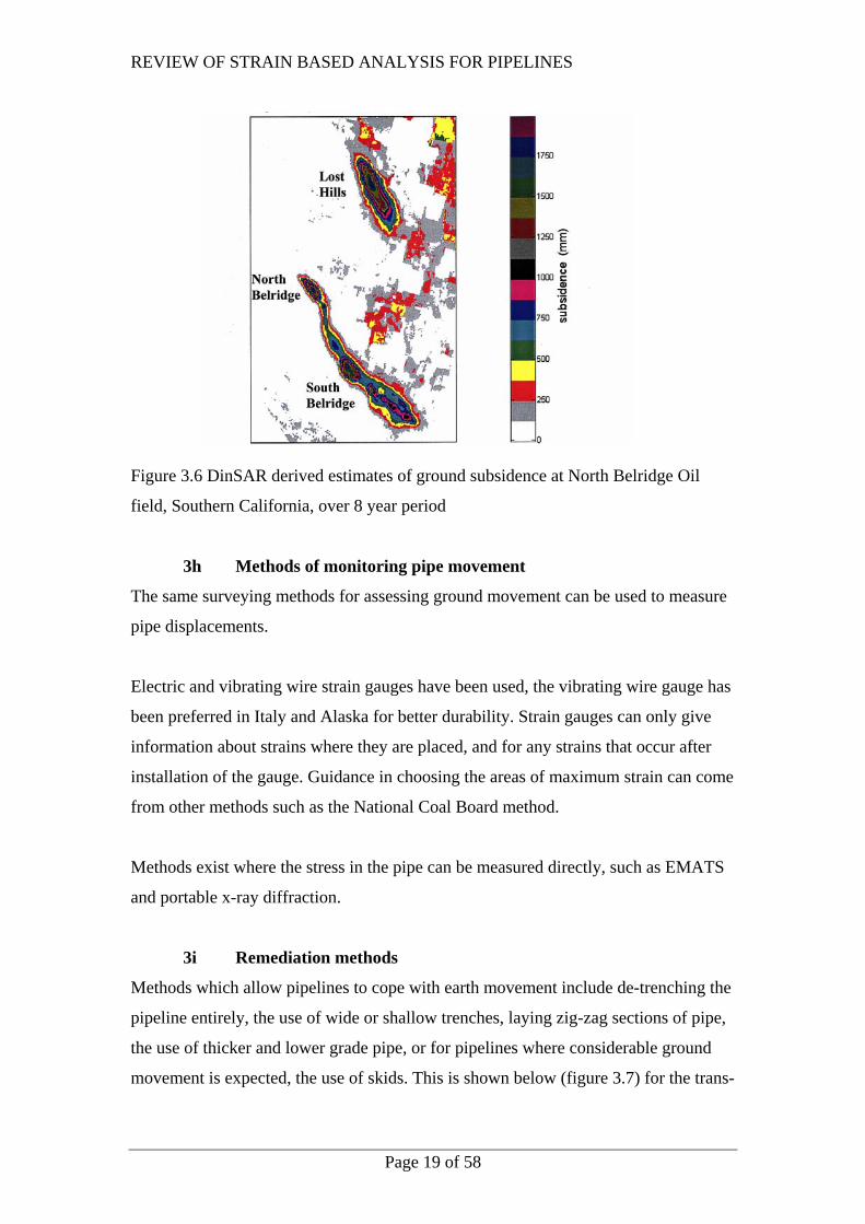
Satellite monitoring has been trialled in Southern California to assess ground
movement in oil fields. Satellite measurements compare well with GPS surveying that
took place over the same time period. The actual technique used repeat passes from
satellites using differential interferometric synthetic aperture radar (DInSAR).
Movements could be detected down to 1 cm, and horizontal components can be
measured as well as vertical (figure 3.6). The area covered can be in the order of 100
km^2.
REVIEW OF STRAIN BASED ANALYSIS FOR PIPELINES
Page 19 of 58
Figure 3.6 DinSAR derived estimates of ground subsidence at North Belridge Oil
field, Southern California, over 8 year period
3h Methods of monitoring pipe movement
The same surveying methods for assessing ground movement can be used to measure
pipe displacements.
Electric and vibrating wire strain gauges have been used, the vibrating wire gauge has
been preferred in Italy and Alaska for better durability. Strain gauges can only give
information about strains where they are placed, and for any strains that occur after
installation of the gauge. Guidance in choosing the areas of maximum strain can come
from other methods such as the National Coal Board method.
Methods exist where the stress in the pipe can be measured directly, such as EMATS
and portable x-ray diffraction.
3i Remediation methods
Methods which allow pipelines to cope with earth movement include de-trenching the
pipeline entirely, the use of wide or shallow trenches, laying zig-zag sections of pipe,
the use of thicker and lower grade pipe, or for pipelines where considerable ground
movement is expected, the use of skids. This is shown below (figure 3.7) for the trans-

REVIEW OF STRAIN BASED ANALYSIS FOR PIPELINES
Page 20 of 58
Alaska pipeline where it crosses an area where a large seismic earth movement
occurred.
Figure 3.7 The trans-Alaska pipeline showing 3 m horizontal displacement after 7.3
magnitude earthquake. The pipeline rests on skids at this point.
3j Summary
Displacement loads can be imposed on pipelines by thermal or seismic loadings, soil
movement, or installation strains. Some analytical methods exist which will
conservatively predict the pipe response; this may preclude the need to further finite
element analysis. More detailed numerical methods take into account increasingly
detailed descriptions of pipe and soil properties and interactions.
REVIEW OF STRAIN BASED ANALYSIS FOR PIPELINES
Page 21 of 58
4 PIPELINE RESISTANCE TO TENSILE STRAINS
4a Plain pipe
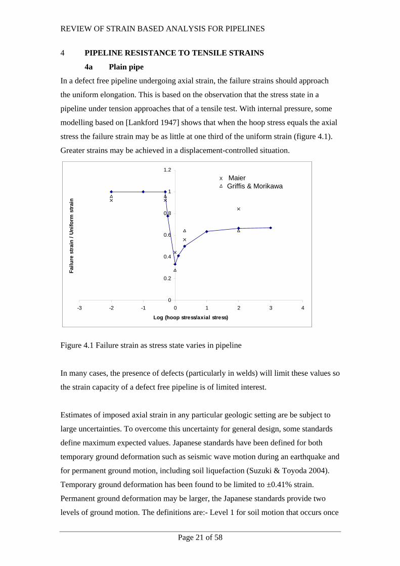
In a defect free pipeline undergoing axial strain, the failure strains should approach
the uniform elongation. This is based on the observation that the stress state in a
pipeline under tension approaches that of a tensile test. With internal pressure, some
modelling based on [Lankford 1947] shows that when the hoop stress equals the axial
stress the failure strain may be as little at one third of the uniform strain (figure 4.1).
Greater strains may be achieved in a displacement-controlled situation.
0
0.2
0.4
0.6
0.8
1
1.2
-3 -2 -1 0 1 2 3 4
Log (hoop stress/axial stress)
Failu
re s
train
/ U
nifo
rm s
train
X MaierGriffis & Morikawa
0
0.2
0.4
0.6
0.8
1
1.2
-3 -2 -1 0 1 2 3 4
Log (hoop stress/axial stress)
Failu
re s
train
/ U
nifo
rm s
train
X MaierGriffis & Morikawa
Figure 4.1 Failure strain as stress state varies in pipeline
In many cases, the presence of defects (particularly in welds) will limit these values so
the strain capacity of a defect free pipeline is of limited interest.
Estimates of imposed axial strain in any particular geologic setting are be subject to
large uncertainties. To overcome this uncertainty for general design, some standards
define maximum expected values. Japanese standards have been defined for both
temporary ground deformation such as seismic wave motion during an earthquake and
for permanent ground motion, including soil liquefaction (Suzuki & Toyoda 2004).
Temporary ground deformation has been found to be limited to ±0.41% strain.
Permanent ground deformation may be larger, the Japanese standards provide two
levels of ground motion. The definitions are:- Level 1 for soil motion that occurs once

REVIEW OF STRAIN BASED ANALYSIS FOR PIPELINES
Page 22 of 58
or twice during the pipeline lifetime and Level 2 for very strong seismic motion due to
inland or trench types of earthquakes likely to occur at a low probability during the
lifetime of gas pipelines. Pipe deformation of the lesser of either ±1% strain or
0.35t/D as a nominal strain is considered the upper limit of Level 1, for which the pipe
should not be severely deformed or require repair. Pipeline deformation of ±3% strain
is considered the upper limit of Level 2 and may also apply to liquefaction cases
(Masuda et. al.).
4b Welded pipe
In most cases, failure from a defect will be from plastic collapse rather than by
fracture as most pipeline steels have good toughness, and because the limited wall
thickness reduces crack tip constraint. One model of defect behaviour suggests that
the behaviour of a defect depends strongly on whether the yield strength of the weld
metal is greater or less than the pipe (over-matching or under-matching) [Denys et. al.
2003].
Defect acceptance limits are based on the behaviour of a pipe under axial tension, if a
pipe with a defect fails in the pipe body, the result is gross-section yielding (GSY), if
it fails at the defect it is net-section yielding (NSY). The acceptable defect size, which
is large, is one that guarantees GSY. One method of estimating the onset of GSY is a
total failure strain in a pipe test over 0.5%. This value is taken as 0.8% in a wide plate
test as the results from wide plate testing are conservative when compared directly to
full scale pipe tests. Defects which result in NSY are large, often greater than 50 mm
long and may be a significant portion of the wall thickness.
In a pipeline built to the usual workmanship defect criteria (Tier 1) of AS 2885.2 there
will be a distribution of defects, mostly of a much smaller size than the maximum
acceptable defect size based on the NSY/GSY criterion. As an upper limit, the
maximum size limit which could exist in a weld after inspection can be used.
Alternatively, a probabilistic assessment can be made of the likely sized defect found
in the length of pipe which is under axial tension (this is limited by friction with the
soil, and is in the order or 1 km).
REVIEW OF STRAIN BASED ANALYSIS FOR PIPELINES
Page 23 of 58
Strain limits can be specified if the likelihood of ground movement can be anticipated
at the time of design. The acceptable defect size which will survive this strain can be
defined and included in the construction specification so that the finished pipeline has
adequate higher strain capacity. A methodology for performing this strain-based ECA
is laid out in [Bratfos 2002].
Internal pressure will raise the axial failure load of a defect, but may reduce the axial
failure strain.
Rather than the Denys criteria of under or over-matching of the Parent and weld YS’s,
an alternative method of assessing defect behaviour is based on FEA modelling of
pipe defects [Benjamin, de Andrade et. al. 2006] and analytical modelling of failure in
un-defected pipe [Law, Fletcher, Bowie 2004]. This suggests the values to be
considered in under- or over-matching are the weld metal UTS [Bratfos 2002] and the
parent metal flow stress or CIS (Cylindrical instability strain defined in [Law,
Fletcher, Bowie 2004]. The use of flow stress or the CIS increases the probability of
GSY occurring compared to the Denys YS criterion.
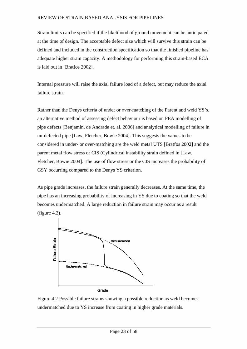
As pipe grade increases, the failure strain generally decreases. At the same time, the
pipe has an increasing probability of increasing in YS due to coating so that the weld
becomes undermatched. A large reduction in failure strain may occur as a result
(figure 4.2).
Failu
re S
train Over-matched
Under-matched
Failu
re S
train Over-matched
Under-matched
Failu
re S
train Over-matched
Under-matched
Grade
Failu
re S
train Over-matched
Under-matched
Failu
re S
train Over-matched
Under-matched
Failu
re S
train Over-matched
Under-matched
Failu
re S
train Over-matched
Under-matched
Grade
Failu
re S
train Over-matched
Under-matched
Figure 4.2 Possible failure strains showing a possible reduction as weld becomes
undermatched due to YS increase from coating in higher grade materials.
REVIEW OF STRAIN BASED ANALYSIS FOR PIPELINES
Page 24 of 58
4c Strain Concentration
Axial strain can concentrate in or adjacent to girth welds. This concentration can also
occur in the weld metal, for instance, due to under-matching. Variability of pipe and
weld metal strength can leave parts of the girth welds locally undermatched. It can
also occur in the heat-affected zone (HAZ), which can soften relative to the base pipe
for some materials.
Description of material behaviour by only the YS, UTS, and the uniform and total
elongation leaves out much of the complexity of the girth weld region. The strength
and strain hardening properties will vary across the HAZ and weld. The weld, HAZ,
and parent metal may not be of uniform strength. Strain localization will be opposed
not only by strain hardening, but also by the restraint of adjacent material that does
not deform as much as the local material. Restraint is particularly effective when the
width of the weak area is small.
Strain may be concentrated at the girth weld by:
• Shape of the cap or root
• Misalignment of the pipe wall centres across the weld
• Differences in thickness across the weld
• Pipe ovality
• Differences in strength in and around the weld.
Some methods of assessing the stress concentrations that come about from these are
found in BS7910 and are demonstrated for fatigue in [Fletcher 1978].
4d HAZ Softening
In most carbon steels, the HAZ increases in hardness and strength when welded, the
effect is typically limited to lower grade steels. However, some combinations of steels
and welding heat inputs can cause the HAZ to soften and become a location where
strain accumulation can occur. Welding at high heat inputs tends to promote HAZ
softening. It can also promote a wider HAZ that reduces the constraint from the
adjacent weld metal and base metal. This subject has been researched by [Mohr
2003].
REVIEW OF STRAIN BASED ANALYSIS FOR PIPELINES
Page 25 of 58
4e Summary
In a defect free pipeline under axial load, the failure strain may lie between 30% and
100% of the uniform strain. In practice, defects in girth welds will reduce this. The
failure strain will depend on the defect size and the material properties of the parent
and weld material. In high grade material HAZ softening may occur, this will
concentrate straining in the HAZ under tension.

REVIEW OF STRAIN BASED ANALYSIS FOR PIPELINES
Page 26 of 58
5 PIPELINE RESISTANCE TO COMPRESSIVE STRAINS
Under compression, the entire span can buckle, either horizontally (snaking) or
vertically (upheaval). Local buckling (wrinkling) may also occur. Buckling is not
necessarily a failure or limit state initially provided that the buckling does not impede
the progress of pigs; pipe integrity may be unaffected. Force-controlled buckling will
reach a maximum moment and fail as an unstable plastic hinge while displacement-
controlled buckling may achieve much larger strains in a stable manner.
“For a pipeline subjected to displacement-controlled loads, the initiation of local
buckling is not a failure condition because of the inherent stability in the displacement
controlled loading process in the post buckling regime” [Glover and Rothwell 2004].
This has been demonstrated in full-scale experiments at the University of Alberta.
Bending leads to tensile and compressive strains, on the tensile side it can fail in the
pipe or at welds; on the compression side it leads to buckling. Most failures occur by
compressive buckling rather than by weld failure caused by a defect due to the small
number of defects present in the bend section (10 – 50 m). Testing for a study on
cold-field bending found that buckling occurred at the same strain for compressive
loading (which created a full-circumferential buckle) and for moment loading (which
created a part-circumferential buckle on the compression side).
Strains in bending are directly related to the pipe diameter and radius of curvature.
ε = r/k where: - ε is the maximum flexural strain, k is the radius of curvature, and r is
the pipe radius.
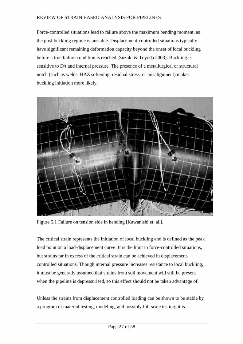
Generally buckling occurs on the compression side of the pipe before tensile failure
on the opposite surface. However, in testing carried on X80 pipe in Japan [Kawanishi
et. al.] failure occurred on the tension side in combined bending and internal pressure
(figure 5.1). This is consistent with modeling carried out for APIA (section 4a) which
suggests low failure strains for combined axial tension and internal pressure loading.
REVIEW OF STRAIN BASED ANALYSIS FOR PIPELINES
Page 27 of 58
Force-controlled situations lead to failure above the maximum bending moment, as
the post-buckling regime is unstable. Displacement-controlled situations typically
have significant remaining deformation capacity beyond the onset of local buckling
before a true failure condition is reached [Suzuki & Toyoda 2003]. Buckling is
sensitive to D/t and internal pressure. The presence of a metallurgical or structural
notch (such as welds, HAZ softening, residual stress, or misalignment) makes
buckling initiation more likely.
Figure 5.1 Failure on tension side in bending [Kawanishi et. al.].
The critical strain represents the initiation of local buckling and is defined as the peak
load point on a load-displacement curve. It is the limit in force-controlled situations,
but strains far in excess of the critical strain can be achieved in displacement-
controlled situations. Though internal pressure increases resistance to local buckling,
it must be generally assumed that strains from soil movement will still be present
when the pipeline is depressurised, so this effect should not be taken advantage of.
Unless the strains from displacement controlled loading can be shown to be stable by
a program of material testing, modeling, and possibly full scale testing; it is
REVIEW OF STRAIN BASED ANALYSIS FOR PIPELINES
Page 28 of 58
recommended that compressive strain limits be based on the critical strain. Once a
bulge initiates, it develops relatively quickly because of the reduced load carrying
capacity in the wrinkled section.
A wrinkle induces significant local deformation of the pipe that may affect the
functionality of the pipeline, for instance, by exceeding the serviceability limit (for
passage of pigs and product) of 5% loss of diameter.
The Australian standard AS2885 allows the use of recognized alternative standards
such as API1111 or DNV-OS-F101 for the design of new pipelines. For existing
pipelines exposed to unforeseen earth movement, a thorough engineering
investigation and safety management study is required which demonstrates that the
strain does not significantly increase the risk of failure. This may be based on the
recognized alternative standards.
5a Compression Limits
The critical strain is same whether this strain is reached by uniform compression, or is
on the compression side in bending. Testing for a study on cold-field bending found
that a full-circumferential buckle in compression occurred at the same strain that
created a part-circumferential buckle on the compression side in bending [Bilston,
Murray 1993].
Published compression strain limits for wrinkling and buckling are not consistent,
with some taking into account YT, internal pressure, the presence of girth welds, or
the local slope of the stress strain curve. There is also great variation in the safety
factors or partial safety factors.
Wrinkling can be set as a possible serviceability limit (SLS):-
• Wrinkling limit εcrit=0.5(t/D’)-0.0025+3000(pD/2ET)2 _________5.1
where D’ is the ovality, D’=0.5D/( 1-3(D-Dmin)/D) [American Lifelines
Alliance]. This equation returns inconsistent results at zero pressure.
• Wrinkling strain εcrit= 0.3t/R [Loeches] _____________________5.2
• Wrinkling limit from Bilston (1993), equation 3.1

REVIEW OF STRAIN BASED ANALYSIS FOR PIPELINES
Page 29 of 58
• A wrinkle may occur at less than half the critical strain for low D/t pipes
[Mohr 2003 EWI report].
A higher limit is the critical strain, defined as the maximum moment on a
moment/curvature graph.
• εcrit =1.76 t/D [American Lifelines Alliance] _________________5.3
• CSA Z662 provides a method of assessing critical strain
where 2)2
(30000025.05.0tE
pDDt
critical +−=ε _________________5.4
Equation 5.4 is identical to the American Lifelines Alliance criteria for
wrinkling (5.1) above except that D, the diameter, is not affected by ovality.
• DNV-OS-F101 also has a method for pipes where D/t < 45:-
RSFGWFYTYSD
t hoopcritical /))()(51)(01.0(78.0 5.1−+−=
σε _____________5.5
,where the hoop stress is defined as P(D-t)/(2t) and the resistance strain factor (RSF)
for class I NDT with ultrasonics in a normal safety class is 2.5. The girth weld factor
(GWF) is defined in the next section. The effect of internal pressure has not been
included (the hoop stress due to pressure is set to zero).
0.0
1.0
2.0
3.0
4.0
5.0
6.0
7.0
8.0
25 35 45 55 65 75 85 95
D/t
Criti
cal s
train
(%)
ALACSADNVAPI 1111
Fig. 5.2 The effect of D/t ratio on critical strain.
API 1111 defines the critical strain as: -
SFDt
critical *5.0=ε _______________________________________5.6
REVIEW OF STRAIN BASED ANALYSIS FOR PIPELINES
Page 30 of 58
,where the suggested safety factor is 0.5. Where the pipe material has a pronounced
yield plateau, the effective safety factor in equation 5.6 is recommended to be reduced
to 0.33. As the DNV-OS-F101 equation (eq 5.5) has a D/t upper limit of 45, the API
1111 equation should be used for higher D/t ratio pipes, but a knowledge of the
factors affecting the DNV equation will improve understanding of possible
conservatisms.
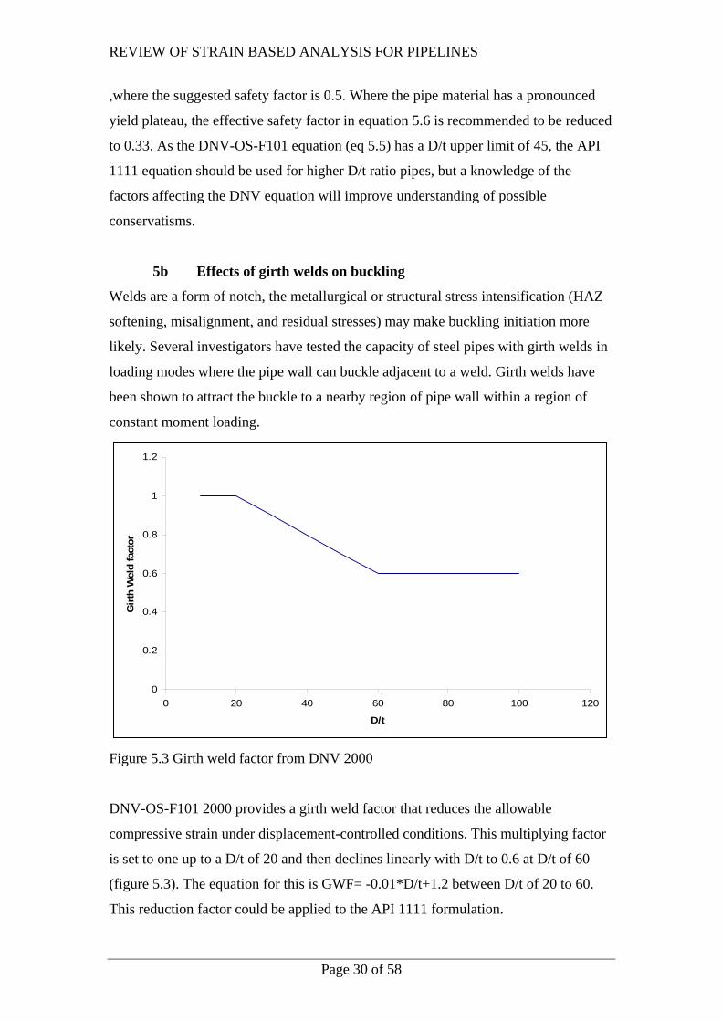
5b Effects of girth welds on buckling
Welds are a form of notch, the metallurgical or structural stress intensification (HAZ
softening, misalignment, and residual stresses) may make buckling initiation more
likely. Several investigators have tested the capacity of steel pipes with girth welds in
loading modes where the pipe wall can buckle adjacent to a weld. Girth welds have
been shown to attract the buckle to a nearby region of pipe wall within a region of
constant moment loading.
0
0.2
0.4
0.6
0.8
1
1.2
0 20 40 60 80 100 1
D/t
Girt
h W
eld
fact
or
20
Figure 5.3 Girth weld factor from DNV 2000
DNV-OS-F101 2000 provides a girth weld factor that reduces the allowable
compressive strain under displacement-controlled conditions. This multiplying factor
is set to one up to a D/t of 20 and then declines linearly with D/t to 0.6 at D/t of 60
(figure 5.3). The equation for this is GWF= -0.01*D/t+1.2 between D/t of 20 to 60.
This reduction factor could be applied to the API 1111 formulation.
REVIEW OF STRAIN BASED ANALYSIS FOR PIPELINES
Page 31 of 58
5c Effects of geometric imperfections on buckling
Imperfections such as ovality (equation 5.1), reduced wall thickness, offset across
welds, and buckles can all reduce the bending capacity of pipelines. In testing on a
pipe with small variations in wall thickness and diameter [Suzuki 2006] the presence
of these defects did not change the failure load (bending moment) but did reduce the
failure strain. FEA was able to predict the failure behaviour with good accuracy.
5d Summary
The critical strain is recommended as a strain limit in buckling. The critical strain is
the strain at the initiation of buckling, and occurs at the maximum bending moment. A
number of different estimates of the critical strain are found in the literature, these
differences increase with the application of the appropriate safety factors or partial
safety factors. The API 1111 equation is the most appropriate equation for predicting
the critical strain for higher D/t ratio pipes, the girth weld reduction factor from the
DNV code could be applied to the API 1111 formulation.
In displacement-controlled situations higher strains may be stably attained, these must
be demonstrated by detailed material testing and numerical modeling. The numerical
modeling may need to be benchmarked by full scale testing, or by numerically
replicating the results of previous full scale tests.
The critical strain is increased by internal pressure; and is decreased by defects,
residual stress, ovality, high YT ratio, and steps in the stress strain curve. In general
the critical strain without any increase from internal pressure should be used, as
internal pressure may not always be present, or the operating pressure may be less
than the design pressure.
The use of low grade pipe with greater wall thickness is recommended in areas that
may experience bending.
REVIEW OF STRAIN BASED ANALYSIS FOR PIPELINES
Page 32 of 58
6 MATERIAL PROPERTIES
6a Materials Testing
More detailed characterisation is required for strain based analysis including the
stress-strain curve of the as-installed pipe, and must include any effects of strain aging
during coating application. The actual stress behaviour should be used in modelling;
the YT ratio is a very blunt measure of pipe behaviour. If full stress-strain curves are
not available, reporting of uniform strain in both axial and hoop direction should be a
standard requirement. The presence of dips on the curve, such as yield plateaus,
reduces the bending capacity of pipe as any steps in the stress-strain curve allow strain
localisation. A stress-strain curve with a monotonically reducing slope appears to
provide the best performance in bending.
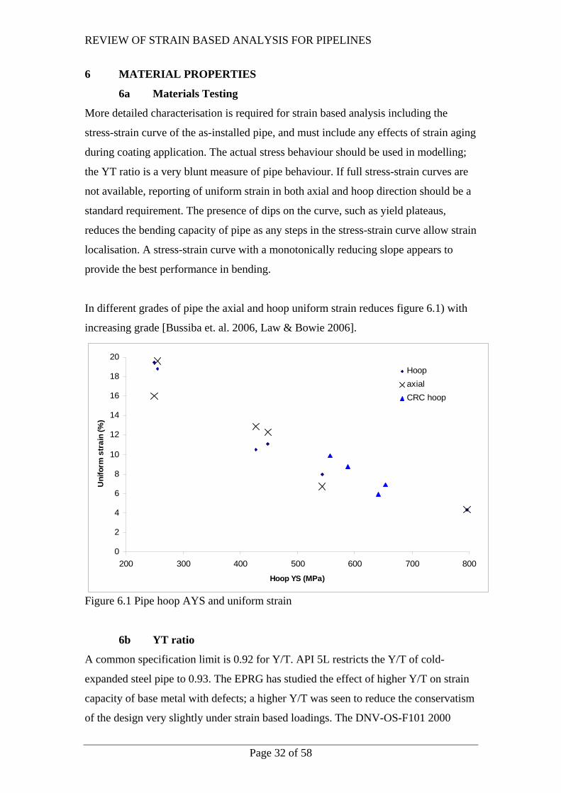
In different grades of pipe the axial and hoop uniform strain reduces figure 6.1) with
increasing grade [Bussiba et. al. 2006, Law & Bowie 2006].
0
2
4
6
8
10
12
14
16
18
20
200 300 400 500 600 700 800
Hoop YS (MPa)
Uni
form
str
ain
(%)
HoopaxialCRC hoop
Figure 6.1 Pipe hoop AYS and uniform strain
6b YT ratio
A common specification limit is 0.92 for Y/T. API 5L restricts the Y/T of cold-
expanded steel pipe to 0.93. The EPRG has studied the effect of higher Y/T on strain
capacity of base metal with defects; a higher Y/T was seen to reduce the conservatism
of the design very slightly under strain based loadings. The DNV-OS-F101 2000
REVIEW OF STRAIN BASED ANALYSIS FOR PIPELINES
Page 33 of 58
standard requires that transverse Y/T be 0.92 or lower for SMYS at 415 MPa or
greater and 0.90 or lower for SMYS below that value. It provides a recommendation
that base metal for use in conditions with accumulated plastic strain >2% have a
maximum Y/T value of 0.85 and a minimum elongation of 15% after strain ageing
(see section 6c). It also reuires increased pipe inspection and restricts the maximum
differences between the pipe end thicknesses and local wall thickness variation. These
improvements in required quality will help to reduce the misalignment bending
stresses at the girth welds.
The measured value of Y/T is critically dependent upon the direction of testing and
the procedures for extracting a tensile specimen.
6c Strain Ageing
Strain ageing is the reduction in ductility and toughness that can occur after plastic
deformation has been applied to steels. Strain ageing occurs at ambient temperatures
and may be accelerated by increased temperature. Strain ageing is noted in steels with
discontinuous yielding.
DNV-OS-F101 2000 requires several additional tests to account for strain ageing
effects on strength, ductility, and toughness on materials where the accumulated
plastic strain will exceed 2%. This level of accumulated strain is achieved by cyclic
loading and then the material is artificially aged at 250oC for an hour. After this it
must meet the normal requirements for hardness, impact toughness. The Y/T limit is
0.85, the YS shall not exceed the SMYS by more than 100 MPa, and the elongation
shall be greater than 15% after strain ageing.
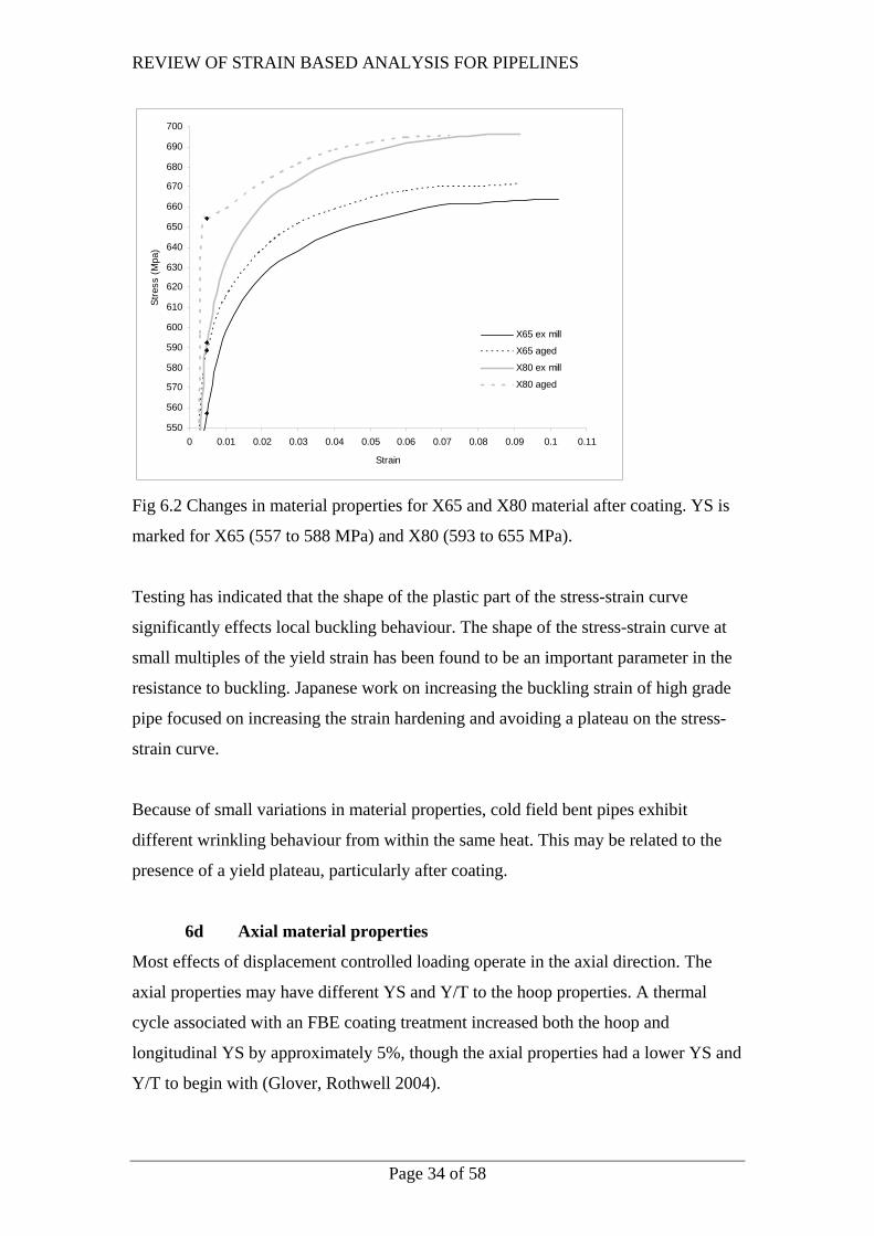
In a previous APIA research project on the effects of Y/T ratio on failure strain,
material was tested in the ex-mill and aged condition. While the X65 material showed
little change in curve shape (figure 6.2), the X80 material went from a “roundhouse”
shaped curve to one with a pronounced step in the stress-strain curve, this would
imply that the ageing process may encourage buckling in a displacement-controlled
situation.
REVIEW OF STRAIN BASED ANALYSIS FOR PIPELINES
Page 34 of 58
550
560
570
580
590
600
610
620
630
640
650
660
670
680
690
700
0 0.01 0.02 0.03 0.04 0.05 0.06 0.07 0.08 0.09 0.1 0.11
Strain
Stre
ss (M
pa)
X65 ex mill
X65 aged
X80 ex mill
X80 aged
Fig 6.2 Changes in material properties for X65 and X80 material after coating. YS is
marked for X65 (557 to 588 MPa) and X80 (593 to 655 MPa).
Testing has indicated that the shape of the plastic part of the stress-strain curve
significantly effects local buckling behaviour. The shape of the stress-strain curve at
small multiples of the yield strain has been found to be an important parameter in the
resistance to buckling. Japanese work on increasing the buckling strain of high grade
pipe focused on increasing the strain hardening and avoiding a plateau on the stress-
strain curve.
Because of small variations in material properties, cold field bent pipes exhibit
different wrinkling behaviour from within the same heat. This may be related to the
presence of a yield plateau, particularly after coating.
6d Axial material properties
Most effects of displacement controlled loading operate in the axial direction. The
axial properties may have different YS and Y/T to the hoop properties. A thermal
cycle associated with an FBE coating treatment increased both the hoop and
longitudinal YS by approximately 5%, though the axial properties had a lower YS and
Y/T to begin with (Glover, Rothwell 2004).
REVIEW OF STRAIN BASED ANALYSIS FOR PIPELINES
Page 35 of 58
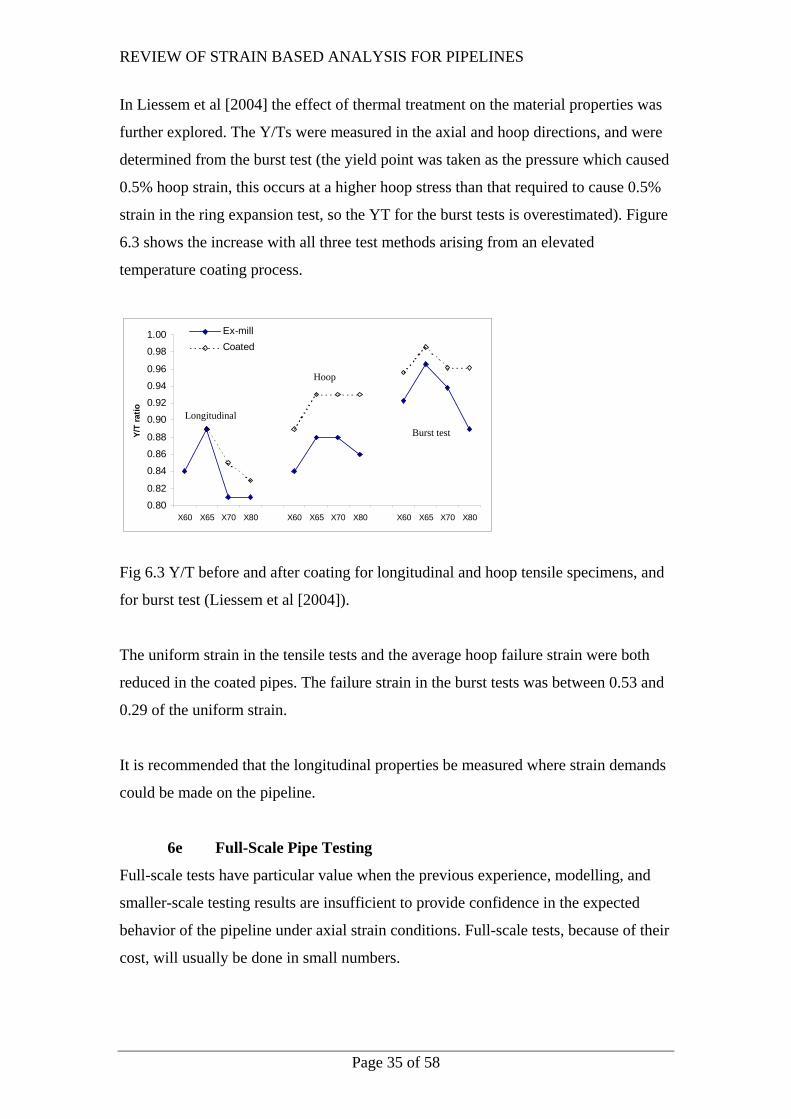
In Liessem et al [2004] the effect of thermal treatment on the material properties was
further explored. The Y/Ts were measured in the axial and hoop directions, and were
determined from the burst test (the yield point was taken as the pressure which caused
0.5% hoop strain, this occurs at a higher hoop stress than that required to cause 0.5%
strain in the ring expansion test, so the YT for the burst tests is overestimated). Figure
6.3 shows the increase with all three test methods arising from an elevated
temperature coating process.
0.80
0.82
0.84
0.86
0.88
0.90
0.92
0.94
0.96
0.98
1.00
X60 X65 X70 X80 X60 X65 X70 X80 X60 X65 X70 X80
Y/T
ratio
Ex-millCoated
Longitudinal
Hoop
Burst test
Fig 6.3 Y/T before and after coating for longitudinal and hoop tensile specimens, and
for burst test (Liessem et al [2004]).
The uniform strain in the tensile tests and the average hoop failure strain were both
reduced in the coated pipes. The failure strain in the burst tests was between 0.53 and
0.29 of the uniform strain.
It is recommended that the longitudinal properties be measured where strain demands
could be made on the pipeline.
6e Full-Scale Pipe Testing
Full-scale tests have particular value when the previous experience, modelling, and
smaller-scale testing results are insufficient to provide confidence in the expected
behavior of the pipeline under axial strain conditions. Full-scale tests, because of their
cost, will usually be done in small numbers.
REVIEW OF STRAIN BASED ANALYSIS FOR PIPELINES
Page 36 of 58
DNV-OS-F101 2000 requires that the characteristic strain capacity from ECA be
“validated by realistic testing of girth welded pipe, e.g., by full-scale bend testing.”
This requirement is applied only for installation methods introducing plastic strains
(such as reeling) for cases where accumulated plastic strain may be >2%, but may be
an appropriate recommendation for all situations where pipes may exceed stress based
limits in operation.
In full-scale testing one must decide what parts of the environmental loading need to
be included: the pressure differential, the longitudinal loading, and the transverse
bending moments.
Full-scale test results of failures of girth weld imperfections in tension have been
collected as part of the validation of ECA methods for pipelines. Tests have been
conducted both under bending alone, and under combinations of bending and internal
pressure [Sen M, Chen J, et. al. 2004]. Much of the ductile fracture testing done to
validate ECA methods has been done on wide-plate specimens. The curved wide-plate
specimens are understood to be conservative compared to the full-scale bend test
results. The effect of internal pressure are not considered in wide plate testing.
6f Optimising materials
In an un-defected pipe subject to axial tension, the presence of a yield plateau is not
significant. Failure strains should show similar results to tensile testing, collapse relies
on the UTS. In displacement-controlled loading, strains above the uniform strain may
be achieved. DNV-OS-F101 2000 specifies that the AYS should not exceed the
SMYS by more than 100 MPa after coating to minimise the chances of the weld
undermatching.
In compression and buckling the shape of the stress-strain curve is more critical. Yield
plateaus cause early wrinkling. Even though there is strain hardening after this, the
presence of a stress concentration from the wrinkle induces further, possibly unstable,
buckling.
Suzuki et al. reported the development of pipe with improved buckling resistance,
based upon increasing the strain hardening and avoiding a plateau on the stress-strain
REVIEW OF STRAIN BASED ANALYSIS FOR PIPELINES
Page 37 of 58
curve at yielding. The strain hardening of interest was over the range of 1 to 4%
strain. The primary testing method used axial compression, but the results were
confirmed for bending loading. The description of a plateau in the stress-strain curve
covers both cases where Lüder’s yielding directly after a sharp yield point, and cases
where flat regions of the stress-strain curve occur after some work hardening.The
tangent modulus, the slope of the stress-strain curve at a given point, goes to zero at
such plateaus, and this correlates to reduced buckling resistance.
6g Summary
Strain-based analysis requires more detailed material properties; preferably the axial
and hoop direction stress-strain curves, but at least it requires accurate YS, TS, and
uniform strain values in both directions. The as-built pipe properties should be used;
particularly with respect to any strain ageing that may occur in coating as this may
lower the buckling resistance.
REVIEW OF STRAIN BASED ANALYSIS FOR PIPELINES
Page 38 of 58
7 ENGINEERING ASSESSMENT METHODS
Few standards have provisions that apply to strain based analysis of pipelines; and
then only in limited situations. Standards give little guidance on implementing strain
based analysis.
“The combined stress limits need not be used as a criterion for safety against
excessive yielding, so long as the consequences of yielding are not detrimental to the
integrity of the pipeline” (provision A842.23 in B31.8)
Engineering Critical Assessment (ECA) is primarily used in strain based design to set
the allowable flaw size for inspection or to check that the material toughness is
sufficient for a given flaw size. The methods are applied to both girth- and seam-
welded areas based on the engineering understanding of brittle and ductile fracture
and plastic collapse.
BS 7910 is a widely used standard for assessing flaws in metallic structures. It
has limited guidance for strain based simplified (Level 1) assessment of fracture, but
not for plastic collapse.
The DNV-OS-F101 2000 standard adds some comments on the procedure used within
BS 7910, since that procedure is designed for stress-based assessment. A material-
specific stress-strain curve is required, as noted in the commentary, so only BS 7910
Levels 2B, 3B, and 3C are accepted. This standard is discussed in relation to cyclic
plastic strains in [Wastberg et.al.].
The single most useful reference found on the subject of strain-based ECA was
published by a member of the DNV [Bratfos 2002]. The full procedural steps for a
strain based assessment are given in Bratfos, many of the steps require the stress strain
curve to be converted to a Ramsberg-Osgood relationship.
In particular the treatment of the failure assessment diagram (FAD) is essential in
performing a strain-based assessment. The option 1 “general” FAD found in level 2
and 3 assessment routes in BS7910 is inappropriate for strain based design as it has a
fixed shape, and is not material specific. The option 2 FAD (“material specific”) is

REVIEW OF STRAIN BASED ANALYSIS FOR PIPELINES
Page 39 of 58
based on the stress-strain curve of the material and is preferred. As most defects fail
by plastic collapse, and the defects inhabit the far right end of the FAD diagram,
defect assessment is sensitive to the value of Lr (the ratio of the reference stress to the
material yield strength) chosen.
In BS 7910-1999 the reference stress is the flow stress, defined as the average of the
YS and UTS (figure 7.1). DNV-OS-F101 2000 defined the reference stress as the
UTS, and this less conservative restriction increases the value of Lr and allowable
stresses by ~10%. It increases the allowable strains by a much larger amount, by
almost 500% (from 1.7% to 8.3 % strain) in the case shown in the Bratfos paper
(figure 7.2).
0
0.2
0.4
0.6
0.8
1
1.2
0 0.2 0.4 0.6 0.8 1 1.2 1.4 1.6 1.8
Lr
Kr
BS7910σ flow/ σUTS
DNV OS-F101σYS/ σUTS
0
0.2
0.4
0.6
0.8
1
1.2
0 0.2 0.4 0.6 0.8 1 1.2 1.4 1.6 1.8
Lr
Kr
BS7910σ flow/ σUTS
DNV OS-F101σYS/ σUTS
Figure 7.1 BS 7910 and DNV Lr
0
0.2
0.4
0.6
0.8
1
1.2
0 0.05 0.1 0.15 0.2 0.25
Strain
Kr
BS7910σ flow/ σUTS
DNV OS-F101σYS/ σUTS
0
0.2
0.4
0.6
0.8
1
1.2
0 0.05 0.1 0.15 0.2 0.25
Strain
Kr
BS7910σ flow/ σUTS
DNV OS-F101σYS/ σUTS
Figure 7.2 Strain-based FAD for figure 7.1

REVIEW OF STRAIN BASED ANALYSIS FOR PIPELINES
Page 40 of 58
The Canadian standard CSA-Z662 provides alternative acceptance criteria for girth
weld imperfections in Appendix K. These criteria do not require explicit accounting
for residual stresses.
The EPRG guidelines [Hohl, Voght 1992] on the assessment of defects in
transmission pipeline girth welds provide a minimum allowable toughness for the pipe
and girth weld areas and provide a plastic-collapse assessment procedure. The plastic-
collapse assessment procedure is used to set the allowable flaw size. However these
assessment methods are based upon load-controlled cases.
There is a lack of safety factors to apply to the ECA procedure for defect analysis or
to use this as a design basis instead of gross or net section yielding criteria.
A flowchart for analysis is given below (figure 7.3). ECA can be used in the final
FEA step when anaylsing defect behaviour in tension.
Material data
Failure ?
Failure limit
from testing
Earth movement
Earth spring
data supplied
Earth movement
data supplied
Earth spring
data supplied
Pipe Response
Piperesponse
(analytical or FEA)
Exceed critical buckling
strain
CompressionSafe
NO
YES
Exceed
critical buckling strain
CompressionSafe
NO
YES
CompressionSafe
NO
YES
Material data
FEA
Failure limit
from testing
Material data
Failure ?
Failure limit
from testing
Weld defect
frequency
Size vs.failurestrain
Maximum defect size
Size vs.failurestrain
Tension
Length of pipe in tension
Tension
Length of pipe in tension
Failure?
ECA and strain limit
Failure?
Pipe soil friction model
Section 3a Section 3d
Section 3d
Section 3d
Section 7
Section 5a
Section 6Section 6
Material data
Failure ?
Failure limit
from testing
Material data
Failure ?
Failure limit
from testing
Earth movement
Earth spring
data supplied
Earth movement
data supplied
Earth spring
data supplied
Pipe Response
Piperesponse
(analytical or FEA)
Exceed critical buckling
strain
CompressionSafe
NO
YES
CompressionSafe
NO
YES
Exceed
critical buckling strain
CompressionSafe
NO
YES
CompressionSafe
NO
YES
Material data
FEA
Failure limit
from testing
Material data
Failure ?
Failure limit
from testing
Weld defect
frequency
Size vs.failurestrain
Maximum defect size
Size vs.failurestrain
Tension
Length of pipe in tension
Tension
Length of pipe in tension
Failure?
ECA and strain limit
Failure?
Pipe soil friction model
Section 3a Section 3d
Section 3d
Section 3d
Section 7
Section 5a
Section 6Section 6
Figure 7.3 Simplified flowchart showing steps in strain based analysis.

REVIEW OF STRAIN BASED ANALYSIS FOR PIPELINES
Page 41 of 58
8 SUMMARY
Strain based analysis is the analysis of structures which are subject to displacement-
controlled loading in the post-yield condition. The differences between stress-based
and strain based analysis only appear above yield, and are more significant with
higher Y/T ratio materials. Above UTS, an increase in load will lead to collapse,
while an increase in the imposed displacement may allow further stable plastic
straining.
Estimates of the soil movement come from geologists. The pipe response to
movement can be made using empirical and finite element methods. Empirical
methods which give upper bound conservative results for strain may be used as a tier
1 assessment and may preclude the need for further analysis.
The strain limits for tensile and compressive cases are not defined adequately, and
many methods contradict each other.
In axial tension the pipe failure strain may be below the uniform strain, and defects
may reduce the failure strain further. Large acceptable defect sizes come about from a
specification for axial failure strain of 0.5%, reduced acceptable defect sizes may be
required for cases where larger displacements and strains are expected.
In bending, failure generally comes about from local buckling. The presence of
metallurgical and geometric notches, and of residual stresses, aids the formation of
buckling. The critical strain is recommended as a limit, though in displacement-
controlled situations, higher strains may be stably attained. Internal pressure raises the
critical strain, but buckling may occur when the pressure is reduced so this effect
should generally be ignored and the pipe should be assumed to be unpressurised.
The results of wide plate testing are conservative compared to the results of full scale
pipe tension tests. Testing or FEA could assess failure strains in a pressurised pipe.
More detailed materials characterisation is required for strain based analysis including
the actual stress-strain curve and YS value after strain ageing. In higher grade
REVIEW OF STRAIN BASED ANALYSIS FOR PIPELINES
Page 42 of 58
materials, coating processes that encourage thermal strain ageing may reduce the
buckling resistance of the pipeline.
Many areas associated with strain based design have been researched within the
framework of limit state design for offshore pipelines; using this design methodology
is acceptable within the existing Australian Standard, but requires the use of partial
safety factors.
There is a lack of safety factors to apply to the ECA procedure for defect analysis or
to use this as a design basis instead of the Denys gross or net section yielding criteria.
Deficiencies in the current state of knowledge that allow strain based analysis of
pipelines to proceed have been identified in the next section. Some of these areas have
been subject to research, particularly by PRCI and University of Alberta [Dorey et. al.
1999, 2000]. A list of reports of interest is included in Appendix A. Some
recommendations for further research are given.
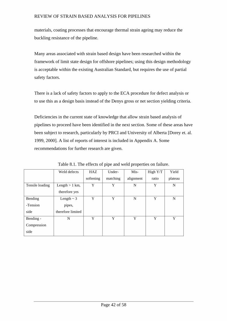
Table 8.1. The effects of pipe and weld properties on failure. Weld defects HAZ
softening
Under-
matching
Mis-
alignment
High Y/T
ratio
Yield
plateau
Tensile loading Length > 1 km,
therefore yes
Y
Y
N Y N
Bending
-Tension
side
Length ~ 3
pipes,
therefore limited
Y Y N Y N
Bending -
Compression
side
N Y Y Y Y Y
REVIEW OF STRAIN BASED ANALYSIS FOR PIPELINES
Page 43 of 58
9 RECOMMENDATIONS FOR FURTHER RESEARCH
Some recommendations for further research are included here, in approximate order
of value. The bulk of this work would be modelling, but full-scale testing will be
required to validate the modelling in some cases. It is possible that the modelling
could be validated by comparison to previous testing in many cases, particularly the
large number of pressurised bend tests from the University of Alberta tests and results
from Rudi Denys at the University of Ghent (described in Appendix A).
Defects in welds
• FEA modelling of the effects of pressure and tension on defect failure strains.
This study should especially target “real” defects which can exist in a weld
after inspection. This work could be carried out with reference to the
BlueScope testing, and any published test data from Rudi Denys and the
University of Ghent. This modelling can be used to assess whether the Denys
pipe YS vs. weld YS criteria or the weld metal UTS vs. parent metal flow
strength is more accurate.
• Are welds undermatched when longitudinal YS is taken into account, after the
pipe has been coated and strain aged?
• The results of defect testing from wide plate tests may give lower failure loads
than full scale tests. The failure strains may be different between wide plate
and full scale tests. FEA can be used to compare wide plate testing with
pressurised pipe.
Tensile failure in un-defected pipe
• FEA modeling can assess the relevance of uniform strain as an axial failure
strain limit, and conditions where this may overestimate the strain reserve.
• Further study is needed on the effects of pressure on the tensile failure
resistance of un-defected welds. This is relevant to higher strength materials
with weaker weld or HAZ.
Buckling failure
• FEA modelling of failure strains of internally pressurised pipe under bending
can be used to investigate effects such as strain hardening and the presence of
a yield plateau.
.
REVIEW OF STRAIN BASED ANALYSIS FOR PIPELINES
Page 44 of 58
• What are the effects of ageing on the shape of the stress-strain curve,
especially on the development of a yield plateau? Does strain ageing reduce
the uniform strain?
• Determination of the preferred shape of stress-strain curves to avoid buckling.
It is expected that the best stress-strain curve will have a monotonically
decreasing slope while a yield plateau should be avoided where buckling is
expected. This has implications for preferred grades and coating systems. This
could be explored with FEA.
Transfer of strain to pipe
• Measurement and modeling of friction between pipe and soil can be used to
assess the length of pipe that is exposed to strain. If this length is small, only a
limited number of possible defects will be present in the affected region,
limiting the likely size of the largest defect.
REVIEW OF STRAIN BASED ANALYSIS FOR PIPELINES
Page 45 of 58
10 REFERENCES
Many of these references have been supplied electronically; the file name is given in
brackets at the end of the reference.
• American Lifelines Alliance “Guidelines for the design of buried steel pipe” July
2001 –(American lifelines pipe.pdf)
• Benjamin A, de Andrade E et. al. (2006) “Failure behaviour of corrosion defects
composed of symmetrically arranged defects” Proc IPC 2006, 6th Int. Pipeline
Conf. Alberta Canada, IPC2006-10266
• Bilston P. & Murray N. (1993) “The role of cold field bending in pipeline
construction” 8th Symposium on Line Pipe Research, American Gas Association,
No. 27, pp. 1-19
• Bratfos H (2002) use of strain-based ECA for the assessment of flaws in girth
welds” Proc. Pipe Dreamer’s Conf. Yokohama, Japan, Nov 2002, pp 957-985
(Bratfos ECA2.pdf)
• Bussiba A, Darcis et. al. (2006) “Fatigue crack growth rates in six pipeline steels”
Proc IPC 2006, 6th Int. Pipeline Conf. Alberta Canada, IPC2006-10320
• BS 7910:1999, Guide on Methods for Assessing the Acceptability of Flaws in
Metallic Structures, British Standards Institution (1999).
• CSA Z662-99 Oil and Gas Pipeline systems, Canadian standards association
• Denys R, Lefevre A, De Baets P (2003) “ Weld and pipe material requirements
for a strain based pipeline design” Journal of Pipeline Integrity, V1 2003 pp5-35
(Denys JPI.pdf)
• Dorey A. Murray D, Cheng J, Grondin G, Zhou J (1999) “Testing and
experimental results for NPS30 line pipe under combined loads” Proc. Of 18th Int
Conf on Offshore Mechanics and arctic Engineering” July 1999. OMAE99 /
PIPE-5022 (dorey bending.pdf)
• Dorey A, Murray D, Chen J (2000) “An experimental evaluation of critical
buckling strain criteria” ASME 2000 Int. Pipeline Conference pp71 – 80 (dorey
Murray critical.pdf)
• DNV-OS-F101, Submarine Pipeline Systems (2000).
• Einsfeld A, Murray D, Yoosef- Ghodsi N (2003) Buckling Analysis of High-
Pressurized Pipelines with Soil-Structure Interaction”. Journal of the Brazilian

REVIEW OF STRAIN BASED ANALYSIS FOR PIPELINES
Page 46 of 58
Society of Mechanical Sciences, v. XXV, n. 2, p. 164-169, 2003.(Einsfeld soil
interaction.pdf)
• DNV-OS-F101 (2000), Submarine pipeline systems standard
• Fletcher L (1978) “The role of longitudinal joint geometry in the fatigue
behaviour of submerged arc welded line” Aust. Welding Journal, Nov/Dec 1978,
pp 18-25 (Fletcher AWJ 1978.pdf)
• Glover A, Rothwell B (2004) “Yield strength and plasticity of high strength
pipelines” International conference on Pipeline Technology, Oostend, Belgium,
May 2004. Volume 1, pp 65-80
• Hebblewhite BK “Regional horizontal movements associated with longwall
mining” (Hebblewhite Mine Subsidence.pdf)
• Ho D, Dominish P “Buried pipelines subjected to mining-induced ground
movements: numerical analysis of the impact and development of mitigation
concepts” Proc 6th Triennial Conf. on Mine Subsidence, 2004 (Ho soil pipe.pdf)
• Hohl, G. A. and Vogt, G. H., “Allowable Strains for High Strength Linepipe,”
Sonderdruck aus 3R International, 31 Jahrgang, Heft 12/92, pp. 696-700,
Vukkan-Verlag, Essen (1992). (Hohl Voght allowable.pdf)
• Honegger G, Nyman D, 2004 “Guidelines for the Seismic Design and
Assessment of Natural Gas and Liquid Hydrocarbon Pipelines” PRCI L51927
(PRCI_seismic designguidelines.pdf)
• ISO/CD 16708 Petroleum and natural gas industries – Pipeline transportation
systems – reliability based limit state methods.
• Kawanishi Y, Masuda T, ET. AL. “Full-scale large deformation tests and ultra
low cycle fatigue tests for evaluating X-80 linepipe performance” International
conference on Pipeline Technology, Oostend, Belgium, May 2004. Volume 4, pp
1881-1894.
• Kiefner JF “Monitoring and intervention on Pipelines in Mining Subsidence
Areas” PRCI catalogue L51515e – (Keifner subsidence L51515e.pdf)
• Kiefner JF, Tuten JM, Wall TA “Preventing pipeline failures in areas of soil
movement – Part 1, State of the Art – A report of 1985 activities” PRCI catalogue
L51516e – (Keifner soil movement L51516e.pdf)
• Law M, Bowie G (2006) “High Y/T and low strain to failure effects in coated
high strength pipe: Final Report” ANSTO Report No. R05M086

REVIEW OF STRAIN BASED ANALYSIS FOR PIPELINES
Page 47 of 58
• Law M, Fletcher L, Bowie G “Burst pressure and failure strain in linepipe: part 3
- Failure pressure calculated by the method of plastic instability” - Journal of
Pipeline Integrity, V3 N2 (2004) pp 106 – 113 (Law papers.pdf)
• Lankford W. & Saibel E. (1947) “Some problems in unstable plastic flow under
biaxial tension” Trans. AIME, Vol. 171, pp. 562-573 (Cylindrical instability
Lankford.pdf)
• Liessem A, Graef MK “Influence of thermal treatment on mechanical properties”
4th International conference on Pipeline Technology, Oostend, Belgium, May
2004. Volume 3, pp 1263-1281.
• Loeches, 4th Init conference on Pipeline technology, Oostend, Belgium, 2004, V3
pp 1393-1404, critical wrinkling strain
• Masuda, T., Kobayashi, T., Yoshizaki, K., and Kobayashi, M., “Recommended
Practice for the Design of Gas Transmission Pipelines in Areas Subject to
Liquefaction,” Pipe Dreamer’s Conference, Yokohama, Japan, pp. 589-599.
• Mohr W (2003) “Strain based design of pipelines” EWI project # 45892GTH
(mohr EWI strain.pdf)
• Selvadurai APS “Soil-Pipeline interaction during ground movement” (Selvadurai
soilpipe.pdf)
• Sen M, Chen J, et. al. (2004) “Full-scale tests on cold bend pipes” Proc Int
Pipeline Conf. IPC04-743
• Suzuki, N. and Toyoda, M., “Seismic Loadings on Buried Pipelines and
Deformability of High Strength Linepipe,” Journal of Pipeline Integrity, v1,
2003, pp 52-66
• Suzuki N, Kondo J, Endo S et. al. (2006)”Effects of geometric imperfections on
bending capacity of X80 Linepipe” Proc IPC 2006, 6th Int Pipeline Conf. Alberta
Canada, IPC2006-10070
• Subsidence Engineers handbook, National Coal Board Mining Department, (UK)
1975
• Trautmann C, O’Rourke T (1983) “Behaviour of pipe in dry sand under lateral
and uplift loading” National Science Foundation Grant #: 8022427 (trautmann
soil pile testing.pdf)
REVIEW OF STRAIN BASED ANALYSIS FOR PIPELINES
Page 48 of 58
• Vito L, Mannucci G et. al. 2005 “ Strain based ECA of double joint pipe subject
to cyclic plastic strains during offshore pipe laying operations” RioPipe, Rio De
Janeiro 2005 IBP1373_05
• Wastberg S, Pisarski H, Nyhus B (2004) “Guidelines for engineering critical
assessment of pipeline installation methods introducing cyclic strain” OMAE04,
22nd Int. Conf. on Offshore mechanics and arctic engineering, June 2004
Vancouver Canada, OMAE2004-51061
• Yimsiri S, Soga K et. al. (2004) “ Laterla and upward Soil-Pipeline interactions in
sand for deep embedment conditions” J. Geotechnical and geo-environmental
Engineering, August 2004 pp 830-842 (yimsiri 2004 lateral soil interaction.pdf)
• Youden J, Power D et al “Satellite-based monitoring of subsidence ground
movement impacting pipeline integrity” Proc. IPC’02, 4th Int. Pipeline Conf.,
Sept 29 – Oct 3, 2002, Calgary, Canada. (Youden satellite monitor.pdf)
• Zhou J, Glover A (2005) “Strain based design of Pipelines- The path forward”
RioPipe, Rio De Janeiro 2005 IBP1353_05
• Zhou W, Nessim M, Zhou J (2005) “ Application of reliability-based design and
assessment to natural-gas pipelines” IBP1024_05 RioPipe05
REVIEW OF STRAIN BASED ANALYSIS FOR PIPELINES
Page 49 of 58
11 APPENDIX A – LIST OF RELEVANT REPORTS
Research of interest
University of Alberta reports
A number of tests of bending in pressurised pipes have been performed and some of
the results published by the University of Alberta by Dorey et. Al., if any more of this
work can be found it would be useful. Some of the references are:-
• Del; Col P Grondin G, Cheng J, Murray D (1998) “Behaviour of large
diameter line Pipe Under Combined Loads” Structural Engineering report No.
224, Dept. of Civil and Environmental Engineering, University of Alberta,
Edmonton, AB, T6G 2G7 Canada
• Mohareb M, Elwi A, Kulak G, Murray D (1994) “Deformation behaviour of
line pipe” Structural Engineering report No. 202, Dept. of Civil and
Environmental Engineering, University of Alberta, Edmonton, AB, T6G 2G7
Canada
• Souza L, Murray D (1994) “Prediction of wrinkling in girth welded line pipe”
Structural Engineering report No. 197, Dept. of Civil and Environmental
Engineering, University of Alberta, Edmonton, AB, T6G 2G7 Canada
• Yoosef-Ghodsi N, Kulak G, Murray D (1994) “Behaviour of girth-welded line
pipe” Structural Engineering report No. 203, Dept. of Civil and Environmental
Engineering, University of Alberta, Edmonton, AB, T6G 2G7 Canada
PRCI reports Extended Model for Pipe Soil Interaction Project Number: PR-271-0184 Catalog Number: L51990
Abstract: The need to extend and improve guidelines on differential landslide ground movement effects and to quantify practical mitigative methods for reduction of these effects on buried gas pipelines led to this program. Many pipeline-soil interaction models have been developed based on research in pipe-soil interaction and anchor plate-soil interaction. Research on anchor behaviors related to pipe-soil interaction will also be covered in this report.
Result: This program contributes to maintaining and improving the integrity and safety of existing pipelines with regard to ground movement hazards, and reducing the capital costs of new pipeline systems. The research program focused on the axial, lateral and complex loading of pipeline due to soil movements. It includes (1) a literature review: it presents significant issues related to modeling pipe-soil interaction with a focus to recent development since ASCE (1984); (2) axial loading: it includes a summary of the methods to estimate the axial soil forces on pipeline and recent field measurements on decommissioned pipe sections in weak to desiccated, cohesive to sandy silts in California; (3) lateral loading of buried pipeline: it covers the effects of cover depth, soil strength, loading rate, trench geometry and backfill strength on pipe-soil interaction; (4) complex loading of buried pipeline: the interaction between the lateral and axial soil forces on pipeline are studied; and (5) quantification of mitigative methods: a physical testing program including a total of 20 laterally loaded pipelines are used to identify and quantify the effects of various mitigative methods on reducing lateral loads transferred to a buried pipeline. Price: $395.00

REVIEW OF STRAIN BASED ANALYSIS FOR PIPELINES
Page 50 of 58
Strain Criteria for the Assessment of Girth Weld Defects Project Number: PR-276-9905 Catalog Number: L51842 Abstract: Need: Most girth weld defect assessment procedures are stress-based. Many geometry and material specific parameters can be neglected to conduct a reasonably accurate stress-based defect assessment. The simplicity of this method is typified by the widely used Level 2 assessment procedure in BS 7910:1999 [1] (successor to PD6493:1991) in the oil and gas industries. However, there are some situations where stress-based defect assessment may not be appropriate. The longitudinal strains can greatly exceed the yield strains in pipelines through discontinuous permafrost, soil or seismic instability, and in offshore pipe laying. The stress-based assessment procedures are incapable of providing safe strain limits for such high strain conditions. Result: This is the first project in a multi-year effort intended to develop alternative defect acceptance criteria for pipelines experience high longitudinal strains. The strain capacity of girth welds containing welding defects is investigated using numerical analysis with comparison to experimental data. The key deliverables of this project are (1) a three-region strain design diagram, and (2) a set of parametric equations allowing the computation of allowable strains with the input of defect depth, defect length, CTOD (Crack Tip Opening Displacement) toughness, and weld strength mismatch. The three-region strain design diagram provides a quick method to determine if a large strain design is possible. The parametric equations can be used to provide a rough estimate of strain limits for a given set of input parameters. Benefit: The results of this project should help the pipeline industry in setting up safe and economical girth weld defect acceptance criteria in new constructions. The defect acceptance criteria have a direct impact on field welding repair rate. In addition, the technology developed in this effort allows the assessment of in-service pipeline integrity when high longitudinal strains are expected. Price: $395.00 Line Pipe Resistance to Outside Force: Assessing Serviceability of Mechanical Damage Project Number: PR-003-9305 Catalog Number: L51832 Abstract: Need: The dominant incident category for gas-transmission piping systems in the U.S. is outside forces. This has been the situation since formal record keeping and trend analysis of incidents began in the 1970s – and this situation is not expected to improve. Acts of nature as well as acts of man are assigned to the “outside forces” incident category. The former tend to have effects that are widespread; examples include damage caused by earthquake, by debris in a river washout resulting from flooding at a river crossing, by large-scale landslides, or by earth subsidence. Because the effects involve multiple joints of pipe, they are easily detected even when the pipeline remains intact; when a failure occurs, it generally is clearly evident, and the effect of that failure on serviceability is usually immediately apparent. Some acts of nature, such as a gradual small-scale slip or subsidence, can have a delayed effect. Here the effect, even though widespread, can go unnoticed until a girth weld or some other part of the pipeline fails. Benefit: This report presents the results of a project whose objective was the development of a “patch” to the PRCI ductile flaw growth model (DFGM), so that this successful technologycould be extended to include mechanical damage. The ultimate goal is a criterion to assess damage severity based solely on field-measurable inputs and nominal information about the pipeline. It is anticipated that such a criterion will lead to cost-effective, timely action to ensure safety and serviceability of high-pressure transmission pipelines, as continuing use of in-line inspection tools makes it increasingly possible to detect mechanical damage. Result: The main conclusion of this report is that growth of mechanical damage on pipelines in typical gas transmission service is contingent on crack initiation during re-rounding of the pipeline. Growth will continue to the pipeline’s maximum allowable operating pressure, or some higher upset or hydrotest pressure in the wake of the damage. For gas-transmission pipelines that experience limited pressure cycling, this observation should simplify decisions concerning what is safe to leave in the line, versus what must be removed. This should make it possible to limit otherwise low-value maintenance and rehabilitation without jeopardizing safety and serviceability. For lines that experience significant pressure cycling, unfortunately, such simplification is not possible regarding repair decisions, because pressure cycling can promote in-service growth from mechanical-damage defects. Price: $395.00 Buckling and Collapse of UOE Manufactured Steel Pipes Project Number: PR-238-9423 Catalog Number: L51809 Abstract: Need: In the past 20 years, much research has been conducted into buckling and collapse of pipelines under external pressure, bending or tension and combinations. Also many finite element analyses have been performed into the behavior of pipelines under these loads. The available test results show considerable scatter, which is
REVIEW OF STRAIN BASED ANALYSIS FOR PIPELINES
Page 51 of 58
considered to be caused by variations in the stress-strain relationship, the anisotropy of the steel, the Bauschinger effect, the geometrical deviations, the residual stresses, the test conditions, etc. The manufacturing method (seamless, UO, UOE) has a considerable influence on these properties and on the collapse and local buckling resistance. Benefit: In this project, design formulations for collapse and buckling with appropriate safety factors, calibrated against experimental and numerical models using probabilistic methods, have been selected for a practical range of design considerations. The project consisted of three parts: experiments, probabilistic calculations, and finite element calculations. Result: It was found that the manufacturing method (seamless, UO, or UOE) significantly influences the collapse pressure and local buckling curvature. For the UOE manufactured pipe, a significant reduction in collapse strength was observed compared to non-expanded pipe. Price: $495.00 Alternative Acceptance Criteria of Girth Weld Defects. Project Number: PR-202-9328 Catalog Number: L51771 Abstract: Need: The girth weld defect acceptance standards based on good workmanship reflect quality levels that can be reasonably expected from a qualified welder. Workmanship (WM) or weld quality standards specify a maximum allowable length whilst the percentage loss of cross-sectional area is used for porosities. This approach to defect acceptance philosophy has arisen from the use of radiography as the NDE technique for detecting and quantifyingweld discontinuities. The first WM standard for inspection and acceptance of finished girth welds was implemented by API in 1953. The specific requirements of the 1953-standard were largely based on the “Unfired Pressure Vessel Code” which was first adopted by ASME in 1931. Since then, a number of slightly revised standards were issued to reflect what should be attainable with normal good welding practices. Result: The failure behaviour of defective girth welds in large diameter pipe lines was assessed using radiographic and mechanized ultrasonic inspection, small scale (tensile, hardness, Charpy and CTOD) and wide plate tests. The specimens were taken from girth welds in API 5LX70 pipe of 1219 mm (48 inches) in diameter by 8,0 mm (0,323 inch) and 13,3 mm (0,524 inch) wall. The test welds were made with the SMAW (8 welds) and GMAW (9 welds) welding processes. Benefit: Upon completion of the non-destructive tests, 96 curved wide plate specimens were tested to destruction under tensile load. Testing was performed at low temperature (-50°C/-58°F). Defect type, defect position and size were determined from photographs of the fracture face and macro sections (defect characterization and sizing). In total, 290 typical surface breaking and embedded defects in SMAW or GMAW girth welds have been evaluated. The vast majority of these defects were grossly out of tolerance with respect to current weld quality (workmanship) acceptance levels. Price: $995.00 Limit States and Reliability-Based Pipeline Design Project Number: PR-244-9517 Catalog Number: L51769 Abstract: Need: To develop fully calibrated limit states design (LSD) procedures for pipelines. Limit states design, also known as load and resistance factor design (LRFD), provides a unified approach to dealing with all relevant failure modes and load combinations of concern. It explicitly accounts for the uncertainties that naturally occur in the determination of the loads which act on a pipeline and in the resistance of the pipe to failure. The load and resistance factors used are based on reliability considerations; however, the designer is not faced with carrying out probabilistic calculations. Benefit: LSD is the way of the future and suggests that if pipelines are designed directly for those scenarios which are known to be the major causes of pipeline failure, the result will be better design in terms of both safety and economy. This study shows that LSD is a rational and logical design process that can provide consistent levels of safety and give the designer a clear picture of the structural response of the pipe for all credible failure modes. Result: This report provides: background information concerning limit states and reliability-based design; limit states design procedures; results of the reliability analyses that were undertaken in order to begin the process of calibration; recommendations for future development work; and several design examples in order to demonstrate use of the method. The reliability analysis work conducted shows that the probability of failure of a defect free pipe subject only to internal pressure is extremely low and emphasizes the need to consider the major causes of pipeline failure (corrosion and outside force damage) in developing and calibrating the limit states design procedures. Preliminary reliability-based analysis work related to calibrating design methods for both of these failure scenarios, as well as a number of others (local buckling, crossings and ductile fracture propagation) is also presented.
REVIEW OF STRAIN BASED ANALYSIS FOR PIPELINES
Page 52 of 58
Price: $895.00 Evaluation of the Structural Integrity of Cold Field-Bent Pipe Project Number: PR-003-9214 Catalog Number: L51740 Abstract: Need: During recent pipeline construction seasons, there have been reported difficulties in cold field bending different joints of line pipe produced by the same manufacturer during a particular production run. These difficulties were typically manifested as an inability to achieve bends of one to one-and-a-half degrees per diameter in the pipe without forming ripples. Some of these problems could be traced to poor bending practices, i.e., inappropriate bending machine set-up and operator inexperience. However, it was observed that even with proper machine set-up and experienced operators, some “bad pipe” exists that could not be bent as far as desired without introducing ripples. Result: The objective of this program was to develop an acceptance criterion for an allowable ripple in a gas-transmission pipeline as a result of a cold field bend. Previous acceptance or rejection criteria for ripples in cold field bent pipe were quite subjective. The purpose of this study was to define quantitative limits for acceptable ripple heights that will not compromise the integrity of the pipe during its expected life. In a program discussed at the 9th PRCI/EPRG meeting, the work performed during a joint Australian Pipeline Industry Association/Line Pipe Research Supervisory Committee effort on the mechanics of cold field bending was presented. Based on theoretical and experimental studies, it was found that modern, high-strength, high D/t pipe forms ripples at very low bend angles during cold field bending. Although there was some circumstantial evidence that some amount of rippling can be tolerated in a pipe, there had been no systematic effort to quantify the influence that the ripples have on the long-term integrity of pipe. Benefit: This report documents the work conducted for the LPRSC study. The details of how cyclic loading experiments were conducted on pipes containing ripples from cold field bending are presented, as well as a discussion of the data that were collected during the experiments. The development of an analytical model to be able to extrapolate to conditions not tested is then presented. The report concludes by offering the supporting evidence for a set of possible new ripple acceptance criteria for modern line pipe. Price: $995.00 Effect of Defect Size and YS/TS Ratio on the Plastic Deformation Capacity of X70 and X80 Pipe Steels Project Number: PR-202-9327 Catalog Number: L51739 Abstract: Need: Modem micro-alloyed low carbon linepipe steels offer an advantageous combination of high toughness levels and a low carbon equivalent (CE or Pcm ) for good weldability. The continuing improvements in pipeline steel manufacturing practices (steelmaking and rolling techniques) have also led to pipeline steels with higher yield-to-tensile (Y/T) ratios and a corresponding reduction in strain hardening capacity. At present, API 5L allows yield-to-tensile (Y/T) ratios up to 0,93 for all linepipe steel grades. The effects of high Y/T ratios on plastic straining capacity and defect tolerance levels are, however, not well documented. The experimental data generated in a previous PRCI sponsored project (Contract no. PR 202-010) have shown that, for 254 mm (1,00 in) thick linepipe steels, flaw tolerance levels reduce with increasing Y/T ratios. This reduced defect tolerance was attributed to a reduction in strain hardening capacity. Benefit: The objective of this research project, which is a logical extension of the work performed under Contract PR 202-010, was to generate additional experimental data to quantify the effect of plate thickness on the relationship between Y/T ratio and tolerable defect dimensions. To that end, an experimental program was undertaken on thin walled X70 and X80 linepipe steels in plate form. Result: This research project generated additional experimental data on the effect of plate thickness on the relationship between yield-to-tensile (Y/T) ratios and tolerable defect dimensions. Several experimental tests were conducted on API 5L X65, X70, and X80 steels, including conventional tensile tests on round-bar, full-thickness prismatic specimens, un-notched wide-plate specimens, and notched wide-plate specimens. The effects of defect geometry and plastic pre-straining (cold deformation) were also studied. The experimental data suggest that the Y/T ratio of thin-walled steels should be limited to 0.90. It was found that high Y/T ratio steels have only a minor resistance to ductile tearing. Using pipeline steels above 0.90 can lead to unsafe conditions, especially when gross plastic deformations may occur. Price: $495.00 Residual Strength of Pipeline Corrosion Defects Under Combined Pressure and Axial Loads Project Number: Report 216 Catalog Number: L51722 Abstract: Need: With the advancing age of the pipeline infrastructure and the competitive marketplace, cost-effective maintenance and rehabilitation is increasingly more important. Accepted methods for evaluating the remaining

REVIEW OF STRAIN BASED ANALYSIS FOR PIPELINES
Page 53 of 58
strength of corroded pipe, while sound and well validated, are empirical in nature and limited to specific classes of corrosion defects. The classical empirical approach, implemented into the ASME B31G "Manual for Determining the Remaining Strength of Corroded Pipelines" was the first "approved" method. PRCI then funded, developed and coordinated the approval by the US DOT of a less conservative method, RSTRENG resulting in improved economics of pipeline repair and rehabilitation. Both of these methods, however, only consider length and depth of the defect and internal pressure loading. In some regions of a pipeline, i.e. mountains and regions of unstable soil, high longitudinal or secondary axial stresses can exist. In these regions, the width of a corrosion defect can limit the pressure capacity of a corrosion defect. The limitations of the empirical models led the pipeline industry to recognize the need for improved understanding and models of the behavior of corroded areas in pipelines subjected to secondary loading. Benefit: PCORR results in more comprehensive analysis of corroded pipe thus resulting in improved safety and performance. The PCORR results are even less conservative than B31G or RSTRENG resulting in improved economics of pipeline repair and rehabilitation. The PCORR software is applicable to existing pipelines using commonly available pipeline data. The model is simple in its input and use. This special-purpose shell finite-element model for analysis of pipeline corrosion defects can be used on standard PC's 386/486 class of IBM PC or higher. Result: The result of this research was the development of an analytical methodology for evaluating corrosion defects under combined internal pressure and axial loads. The research investigation resulted in a broadly based program incorporating full-scale experiments, finite element investigations, and the development of fundamental mathematical and computer models. A comprehensive mathematical "model" in the form of a software program called PCORR was developed to calculate the safe pipeline operational limits under combined internal pressure and axial loads. A secondary result was the extension of this methodology to evaluate the interaction of adjacent defects, an area where the empirical models were not applicable. Price: $1,095.00 Effect of Defect Size and Yield to Tensile Ratio on Plastic Deformation Capacity Pipeline Steels Project Number: PR-202-010 Catalog Number: L51686 Abstract: Need: Micro-alloyed low-carbon linepipe steels offer an advantageous combination of high toughness and a low carbon equivalent (CE or Pcm) for good weldability. The continuing improvements in pipeline steel manufacturing practices have also led to pipeline steels with higher yield to tensile (Y/T) ratios and a corresponding reduction in strain hardening capacity. Potential users of high Y/T ratio pipeline steels are somewhat reluctant to modify their existing specifications. This is because they do not have the required information to judge the performance characteristics of such steels under a wide range of service conditions. This is not surprising knowing that yielding behaviour, and defect tolerance in particular depends not only on toughness but also on the strain hardening capacity. Therefore, the interaction between toughness and strain hardening capacity (or Y/T) for a successful application of high Y/T ratio linepipe steels must be considered. For the pipe fabricator this means that not only the yield strength of the plate, used to make the pipe, must be carefully controlled, but also that the relationship between the mechanical properties of pipe and plate must be known. Benefit: This study examined the engineering significance of the yield-to-tensile (Y/T) ratio on yielding behavior and defect tolerance of 1-inch thick X70 steels in plate form. Stress-strain characteristics were measured by tensile testing of standard round-bar, full-section square, and wide-plate specimens. The strained condition was tested to determine the effect of cold forming on the Y/T ratio and yielding behavior. Finally, defect tolerance was determined by testing 8-inch wide notched-plate specimens. Results: The present work has enabled the following conclusions to be drawn :The round bar yield strength depends on specimen diameter and sampling location. Sub-surface tensile specimens gave higher yield strengths than plate mid-thickness specimens because of the hardness gradient in the plate through thickness direction. The higher yield strengths produced a corresponding difference in Y/T ratio. The plate mid-thickness round bar specimens gave lower Y/T ratios than rectangular full section specimens. Sub-surface round bar specimens gave higher Y/T ratios. The yield criterion used (0,2% or 0,5% offset) greatly affects the Y/T ratio. The 0,5% offset yield strength which is the value normally used, was found to be less sensitive to specimen cross sectional area. Each of the steels investigated was susceptible to strain aging when loaded to three percent (3 %) straining and aged at ambient temperature for 6 months. Steel having an acicular-ferrite (AF) microstructure (or a continuous stress-strain behaviour) were found to age more rapidly than a ferrite-pearle (polygonal ferrite) (PF) microstructure having a discontinuous stress-strain behaviour. The strain aging produced a substantial increase of Y/T ratio. The ratios increased from about 0,90 to 0,95 (PF microstructure) and, from about 0,86 to 0,99 (AF microstructure). The notched wide plate test results showed that the yielding behaviour, strain capacity and defect tolerance are closely related to Y/T ratio. Increasing Y/T ratios gave a reduction of the maximum through thickness defect length, agy , for Gross Section Yielding (GSY). Moreover, the results of this investigation have shown that a correlation agy and Y/T ratio does exist, and that this correlation can be used to define a maximum Y/T ratio for a given tolerable defect size for GSY. Price: $995.00
REVIEW OF STRAIN BASED ANALYSIS FOR PIPELINES
Page 54 of 58
Investigate Hydrogen-Related Failure at Mechanical Damage Project Number: Report 189 Catalog Number: L51621 Abstract: Need: Leaks attributed to hydrogen-stress cracking (HSC) initiating in regions of mild mechanical damage have been reported in cathodically protected pipe lines constructed from high-strength, microalloyed, controlled-rolled steels. The hydrogen is believed to be present in service from the cathodic potential applied. Benefit: Laboratory studies were initiated to determine the factors that contributed to those unexpected failures. Strain aging at ambient temperatures as a result of deformation introduced during the mechanical damage, was found to be a significant factor. Smooth-bar specimens that were strained and then aged failed by HSC within one week, whereas specimens that were not strain aged did not fail by HSC. Result: The findings of this research indicate a potential sequence of events which may lead to hydrogen-related failures in regions of mild mechanical damage: (1) Following the damage, ambient-temperature strain aging which promotes sensitivity to HSC takes place in the mechanically damaged region, in a surface layer of the pipe wall which has been subjected to a critical level of strain. The time period for this step would be on the order of several years. (2) Electrochemical conditions which promote hydrogen charging develop at the pipe surface from the cathodic current applied (or possibly corrosion). (3) Local stresses in the mechanically damaged region are elevated above the threshold stress for HSC by the moderate stress concentration provided by the mechanical damage. For the X70 pipe studied, the stress elevation should be at least 20 percent above the nominal hoop stress. (4) An HSC crack initiates and grows in the strain-aged surface layer. (5) The crack propagates further by HSC, through the non-strain-aged portion of the wall, as a result of the high stress concentration at the crack tip. (6) When the crack grows to a critical depth, it propagates rapidly through the wall by overload and causes a leak. Price: $349.00 Non-Conventional Means for Monitoring Pipelines in Areas of Soil Subsidence or Soil Movement Project Number: Report 166 Catalog Number: L51574 eBook Version Available: Yes, L51574e Abstract: Examines non-conventional techniques for monitoring curvatures, displacement, or strains in buried pipelines. Internal devices, external devices, and fiber optic techniques were examined. Feasibility of each system is discussed and the most promising are identified. Two companion studies 'Guidelines Pipeline Strain Monitoring by Conventional Means' (Reference 1) and 'A Proposed Model for the Intervention Decision Making Process in Pipeline Movement Situations' (Reference 2) have already been completed, and an effort to determine appropriate failure criteria for pipelines in areas of soil instability is currently underway. The objective of this study is to describe methods of pipeline monitoring which are, for the most part, still in the conceptual and/or development phases. It is very likely that the techniques described herein will require extensive validation efforts and significant financial support before they will become reliable tools for routine use Improved pipeline strain monitoring techniques are needed because the conventional techniques (strain gages, inclinometers, and topographical surveying) meet all of the industry's needs. The conventional techniques are expensive, labor intensive, and require access to the pipeline for installation . As such they are limited in use to localized trouble spots that are known to be a problem. None of these techniques could be practically applied to a whole pipeline for any-time monitoring. Techniques that will better satisfy the industry's needs must be adequately sensitive, applicable to the whole pipeline, available at all times (or at least at reasonably frequent intervals), and capable of use without the need to excavate the pipeline or to interfere with its operation. Several non-conventional techniques for monitoring curvatures, displacements, or strains in buried pipelines that may meet these requirements are discussed herein. These fall into three generic classes: internal devices (instrumented pigs), external devices (involving moving a detecting device over the pipeline right-of-way), fiber-optic cables attached to the pipeline over its entire length. Price: $349.00 Yield Tensile Ratio Effect on Line Pipe Behavior Project Number: Report 168 Catalog Number: L51562 Abstract: Need: Considerable research has been conducted to define the significance of the yield-to-tensile (Y/T) ratio for line-pipe steels. In the late 1960s and early 1970s, a study was completed in which a series of burst tests was conducted on 41 pipes ranging from 8 to 42 inches in diameter and representing API Specification 5L Grades A through X65. In this study, only 2 of the 41 materials studied had a yield-to-tensile ratio greater than 0.9, and these were artificially created. With the advent of the X70 and X80 steels, higher yield-to-tensile ratios have developed as the yield strength increased. A re-examination of this question in terms of the higher strength materials is presented herein. Benefit: The objective of this research is to determine if the high yield-to-tensile ratio of X70 and X80 line-pipe steels in any way restricts such operating practices as hydrostatic testing, operating stress level, and flaw behavior.

REVIEW OF STRAIN BASED ANALYSIS FOR PIPELINES
Page 55 of 58
Result: The conclusion from this study is that there appears to be no reason why high yield-to-tensile pipe should not be used for line pipe. The advent of new steel making and rolling practices can produce pipe with the fracture toughness and fracture propagation transition temperatures that are required for fracture control. Because the higher yield-to-tensile pipe has a higher yield stress than the specified minimum yield stress, it is less likely to yield in a hydrostatic test taken to the specified minimum yield stress than is lower yield-to-tensile pipe. Price: $349.00 Plastic Collapse Solutions for GW Pipes and Sleeves Project Number: PR-185-9431 Catalog Number: L51761 Abstract: Need: All welded structures enter service containing some flaws or imperfections. These may range from volumetric indications, such as inclusions and porosity, to planar flaws, such as lack of side-wall fusion or hydrogen cracking. Depending on the form of applied loading and the operating environment, a flawed structure may fail by a number of different modes. For static loading, the extreme failure modes are brittle fracture (fracture preceded by minimal plastic deformation) and plastic collapse (plastic overloading of the remaining ligament of a cracked body). To prevent such failures, it is imperative that a fitness-for-service (FFS) assessment methodology include the capability to analyse both failure modes. The existing FFS assessment procedures in API 1104 are based solely on fracture considerations. In comparison, the FFS assessment procedures included in the CSA Z662 are based on both fracture and plastic collapse considerations. Other assessment procedures, such as PD6493:1991 CEGB R-6Rev3, and the GE/EPRI J Estimation scheme consider the plastic collapse as an integral part of the assessment methodology. Although FFS assessment procedures based on fracture considerations should, in general, produce conservative assessments, plastic collapse may be the limiting failure mode in certain cases. As a result, it is Important to develop plastic collapse assessment procedures for both pipeline girth welds and welded sleeve assemblies to enable development of comprehensive FFS assessment procedures. Result: The results of this project developed plastic collapse solutions for girth-welded and welded sleeve assemblies with circumferential cracks. The first phase of this project involved nonlinear finite element analysis (FEA) of pipes with circumferential cracks of different size. Provisional plastic collapse solutions were developed based on a large number of analyses. The second phase of this project involved full-scale tests of two 16-in. (406-mm) X60 pipes with circumferential cracks at the fillet weld toe of full-encirclement sleeves. The pipes were loaded by internal pressure and lateral four-point bending until burst at the crack locations. The loads at failure were recorded and compared with the provisional solutions developed in Phase 1 of the project. Other commonly used plastic collapse solutions were examined in both Phases 1 and 2 to determine their relative degree of conservatism. Benefit: The project considered over 120 cases of circumferentially-cracked pipes that were analyzed under a variety of loading conditions. The provisional plastic collapse solutions were developed by first identifying the most accurate solutions available for girth-welded pipes under pure lateral bending. Six available solutions were reviewed and recommended within the body of this study. Price: $495.00 Investigation of Wrinkling at Low Bend Angles During Field Bending of Line Pipe Project Number: Report 150 Catalog Number: L51473 Pages: 32 Abstract: Need: Severe problems with wrinkling when making field bends in ERW pipe coated with a fusion-bonded thin-film coating have been reported by several PRCI member companies in recent years. When these problems were encountered, wrinkling was controlled by careful alignment of the bending equipment, by procuring another lot of pipe for bending, or by increasing the bend radius. The occurrence of wrinkling results in considerable inconvenience, such as increased cost and construction delays, particularly when it cannot be controlled solely by realignment of the bending equipment. Results: An investigation was conducted to determine the factors responsible for the development of wrinkles at low bend angles during the field bending of certain lots of line pipe. The investigation included both a survey of users to obtain information on field bending problems and laboratory studies at Battelle designed to identify factors responsible for wrinkling at low bend angles. Benefit: It was found that wrinkling has been observed in a wide range of pipe sizes and grades. In all cases in which wrinkling has been observed at low bend angles during field bending, it occurred in pipe that had been coated with a fusion-bonded thin-film coating. However, not all fusion bonded thin-film-coated pipe has exhibited bending problems. The thermal treatments used to apply fusion-bonded coatings to line pipe can result in a change in the yield behavior of the pipe; that is, discontinuous yielding may be enhanced as a consequence of strain aging. Local-buckling theory suggests that the occurrence of discontinuous yielding should increase the likelihood of
REVIEW OF STRAIN BASED ANALYSIS FOR PIPELINES
Page 56 of 58
wrinkling during field bending. This factor is believed responsible for the greater susceptibility to wrinkling of pipe coated using a fusion-bonded thin-film coating, compared with uncoated pipe from the same lot of pipe. Price: $195.00 Integrity and Remaining Life of Line Pipe with Stress Corrosion Cracking Project Number: PR-186-9709 Catalog Number: L51928 Abstract: Need: Stress-corrosion cracking (SCC) is an important issue to address in evaluating pipeline integrity. Methods of predicting the failure and remaining life of pipelines with SCC defects or the potential for containing SCC defects are needed to ensure safe and reliable pipeline operation. Result: The CorLAS computer program for corrosion life assessment of piping and pressure vessels was found to provide very good predictions of actual SCC failure conditions, but it gave somewhat conservative predictions for very long cracks. This research project was undertaken to develop improvements to CorLAS. Benefit: The objective of research project PR 186-9709 was to improve the CorLAS Version 1.0 model for predicting the failure and remaining life of pipelines with stress corrosion cracks Price: $995.00 Interaction of Multiple Through-Thickness Defects under Plastic Collapse Conditions (Part I) Project Number: PR-202-9514 Catalog Number: L51780 Abstract: Need: The currently used defect interaction rules assume elastic fracture behaviour. The use of these rules for ductile materials results in higher rejection and repair rates. Realizing that girth welds in thin-walled pipelines fail primarily by plastic collapse, the applicability of linear elastic fracture mechanics based interaction rules for thin-walled structures is brought into question. This conclusion, in conjunction with the improved resolution of non-destructive techniques, gave the impetus to conduct research into the interaction of defects in thin-walled structures subject to plastic collapse. Benefit: The objective of this research project is to generate experimental information with the aim to quantify the conservatism of current interaction rules and to develop more accurate (less conservative) rules for ‘thin-walled’ structures under plastic collapse. The conservatism in current defect interaction rules for ductile materials has been assessed by examining the failure behaviour of 8 mm and 10 mm thick, narrow (width: 100 mm and 120 mm) and wide (width: 427 mm) plate, specimens containing two coplanar or non-coplanar through thickness notches. The test results were compared to the failure characteristics of single notched plates and analysed in terms of Gross Section Yielding (GSY). The tests were conducted on three different materials in order to determine the effect of the Y/T ratio on defect interaction behaviour. Result: The key findings suggested by the results of the experiments can be summarized as follows: 1. If the total length of two neighbouring coplanar notches (I1 + I2 ) is smaller than the defect length for GSY (a,,), GSY is ensured irrespective of overall defect length (I1 + s + I2 ). That is, coalescing neighbouring coplanar notches in the GSY regime can be considered as non-interacting notches implying that current interaction rules are highly conservative if I1 + I2 < agy. 2. If the total notch length (I1 + I2 is greater than the maximum defect length for GSY (agy ) GSY can still be obtained when the separation distance between the adjacent notches is greater than the sum of the length of these notches (s > I1 + I2 ). 3. Any offset between the notch planes has a positive effect on the deformation behaviour of a plate containing two collinear, non-coplanar notches if the angle between the inner notch tips is greater than 30°. After 45° the notches do not influence each other. Parallel notches (notch tip angle of 90°) of the same length behave as a single notch. 4. The observed trends in defcet interaction behaviour are not affected by the Y/T ratio. However, Y/T ratio has a strong influence on the value of agy. The above observations demonstrate that the defect length, agy , which characterizes the transition between NSY and GSY is a key parameter in the developing of defect interaction rules for ductile material behaviour. The results of this research project have also shown that a conservative estimate of the value of agy can be obtained from the yield to tensile ratio and the width of the plate. Price: $495.00 Effects of Welding on HAZ Softening of X70 / X80 TMCP Linepipe Steels Project Number: PR-202-9635 Catalog Number: L51926 Abstract: Need: Developments in controlled rolling and accelerated (water) cooling techniques in plate mills in the early 1980’s have made it possible to produce micro-alloyed high strength line pipe steels with very low carbon contents (C < 0.05 %). The lean chemistry of these high strength TMCP steels provides moderate hardenability, excellent weldability and adequate low temperature heat affected zone (HAZ) toughness. However, the lean chemistry and, in particular, the low C content, requires carefully controlled welding procedures to achieve adequate strength in the weld HAZ. It is essential, therefore, to characterize the hardness, strength (and toughness) properties of the

REVIEW OF STRAIN BASED ANALYSIS FOR PIPELINES
Page 57 of 58
variety of microstructures occurring in the HAZ of lean alloyed high strength line pipe steels. More specifically, a better understanding of the parameters affecting the strength and hardness properties of low alloy TMCP pipeline steels subjected to welding is required. The mean parameters contributing to HAZ softening are : steel chemistry, plate and pipe manufacturing route, weld heat input (including the effects of preheat and interpass temperature) and the number of weld cycles. Result: Experimental work was done to evaluate the effects of welding on the hardness, tensile and toughness properties of the heat affected zone (HAZ) of a series of commercial high strength micro-alloyed linepipe steels, produced through controlled rolling and accelerated cooling (thermo-mechanical control process - TMCP). The test materials, representative of modern low carbon linepipe steels, were selected such as to cover a broad range of chemistries (alloy /micro-alloy designs) and mechanical properties (X 70 and X 80). Benefit: Special emphasis was placed on verifying the susceptibility of the steels to the occurrence of(yield strength) softening in the weld HAZ and on characterizing the toughness properties of the grain coarsened HAZ. This objective was achieved by means of the weld thermal simulation technique. By the application of thermal cycles representative of those occurring in the HAZ of pipeline girth welds made with moderate to high heat inputs, a broad range of HAZ micro-structures covering the complete weld HAZ were synthetically (artificially) produced in each of the steels. The properties of these well-defined microstructures were subsequently determined by optical metallography, hardness, tensile and Charpy V impact testing. Price: $995.00 Hydrogen Cracking in the Heat Affected Zone of High Strength Steels--Year 2, Development of Weld Metal Test Project Number: PR-225-9516 Catalog Number: L51764 Abstract: During year 1 of this project a test to evaluate the sensitivity of the heat affected zone (HAZ) to hydrogen cracking was developed. This was in response to a need for a test which provided unambiguous results in contrast to existing test methods which often led to difficulties in interpretation. For example, WIC tests usually cracked in the weld metal rather than the HAZ and therefore did not produce a clear indication of the sensistivity of the HAZ. The new test involves a machined notch which can be placed in the HAZ thus forcing crack initiation to occur in the desired region. A further advantage of the new test is that it is quantitative with each test specimen providing a measure of the sensitivity of the HAZ in that test. Existing tests are usually of the crack/no-crack type requiring a series of tests at different preheats to be carried out in order to establish a critical value. This is an expensive, time-consuming approach. The new test measures the deflection to first load drop (normally the onset of significant cracking) when the welded specimen is loaded in bending. It was also shown during the first year of the project that the simple geometry of the test lends itself to easy analysis enabling the stress/strain distribution to be calculated by finite element analysis. The quantitative measurement of susceptibility in the test enabled the cracking of more complex welds to be predicted on the basis of a local critical hydrogen model. Benefit: The objective of the work was to extend the notched bend test to the evaluation of weld metal sensitivity to hydrogen cracking. The experiments were designed to determine whether the test could discriminate between two different weld metals and to study the effects of reducing hydrogen content. In addition, finite element analysis of the weld metal test was carried out and finite difference analysis used to predict the local hydrogen concentration. This work modifies the notched bend test, developed for evaluating the sensitivity of the heat affected zone (HAZ), to allow the evaluation of weld metal. The results showed that weld metal could readily be evaluated, with the test discriminating among weld metals of different composition and hydrogen contact. Finite element analysis was undertaken and showed that for the two weld metals tested, cracking occurred at the same local stress when the hydrogen content was the same, despite differences in strength. A finite model was used to calculate the distribution of hydrogen as a function of aging time. Although the general trends were confirmed by the experimental measurements of hydrogen content, there was considerable scatter attributed to the small hydrogen volumes measured. Result: The work reported here continues previous work on a test to evaluate the hydrogen crack susceptibility of the HAZ, extending it to an evaluation of weld metal. The weld metal version of the test is essentially the same as the HAZ test except that the Charpy V-notch is placed in the weld metal. Tests with two weld metals on as-welded samples and on samples aged after welding to reduce the hydrogen level, led to the following conclusions: • The notched bend test provides a useful means of evaluating the susceptibility to hydrogen cracking of weld metal. No practical difficulties were experienced in applying the test to weld metal, and the notch could be placed in the desired location within the expected tolerances. • Non-aged samples showed good reproducibility and clearly discriminated between the two weld metals. • Cracking appeared to initiate in a zone close (about 0.5mm) to the notch tip. • Aged samples of E6010 weld metal with low levels of hydrogen showed maximum load behavior accompanied by tearing from the notch tip. E8010 weld metal samples showed sudden load drops regardless of hydrogen content. • In the E6010 weld metal significant HAZ underbead cracking was also observed which may have influenced the critical deflection measured. This was attributed to the high susceptibility of the pipe material use for the test specimens. • Finite element analysis showed that the stress state in a region about 0.5 mm from the notch tip was the same at the critical deflections for the two weld metals tested. Thus in these tests the difference in

REVIEW OF STRAIN BASED ANALYSIS FOR PIPELINES
Page 58 of 58
susceptibility could be explained in purely mechanical terms. • A finite difference model was used to calculate the distribution of hydrogen as a function of ageing time, and although the general trends were confirmed by experimental measurements of hydrogen content, there was considerable scatter attributed to the measurement difficulties with very small hydrogen volumes. Price: $749.00