Embed Size (px)
Citation preview
114 | P a g e
REVIEW OF NITROGEN FLUSHING TECHNOLOGY
IN COMBATTING MINE FIRES
Nikhil Jain1, Adarsha Das
2, Akash Srivastava
3, Dr. N.C. Karmakar
4
1,2IDD Student,
3B. Tech Student, Indian Institute of Technology, (Banaras Hindu University),
Varanasi, (India)
4Professor, Dept. of Mining Engineering, Indian Institute of Technology,
(Banaras Hindu University), Varanasi, (India)
ABSTRACT
The elementary aim of the analysis is to probe gas mixing and dilution approaches to provide with an
improved apprehension of processing of satisfactory levels of contamination inside a mine ambience, which
can be assessed. As an illustration the interaction between gases from inertization systems and the
underground mine atmosphere can be judged to serve in design of the mine inertization system. Inertization
approaches admit the usage of engine exhausts, nitrogen, carbon dioxide, and diesel fired boiler units. For the
important safety approaches inside the many parts of the international industry, inertization systems have been
assumed for handling underground fires, spontaneous combustion heating and management of the potential
explosibility of newly sealed goafs. For the explanation of designs and applications of inertization systems in
stabilizing mine atmosphere is assisted by few given case studies.
Keywords: Nitrogen Fluhsing, Mine Fires, İnertization, Underground Mine, Coal, PSA.
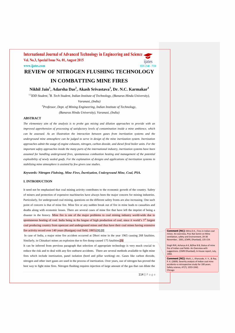
I. INTRODUCTION
It need not be emphasised that coal mining activity contributes to the economic growth of the country. Safety
of miners and protection of expensive machineries have always been the major concern for mining industries.
Particularly, for underground coal mining, questions on the different safety fronts are also increasing. One such
point of concern is that of mine fire. Mine fire or any sudden break out of fire in mine leads to casualties and
deaths along with economic losses. There are several cases of mine fire that have left the imprint of being a
disaster in the history. Mine fire is one of the major problems to coal mining industry world-wide due to
spontaneous heating of coal. India being in the league of high production of coal, since it world‘s 3rd
largest
coal producing country from opencast and underground mines and thus have their coal mines having extensive
fire activity record over 140 years (Raniganj coal field, 1865).[1].[2]
In case of India, a major mine fire accident occurred at Dhori mine in the year 1965 causing 268 fatalities.
Similarly, in Chinakuri mines an explosion due to fire dump caused 175 fatalities.[3]
It can be inferred from previous paragraph that selection of appropriate technology is very much crucial to
reduce the risk and to deal with any fire outburst accidents. There are several methods available to fight mine
fires which include inertization, panel isolation (bord and pillar working) etc. Gases like carbon dioxide,
nitrogen and other inert gases are used in the process of inertization. Over years, use of nitrogen has proved the
best way to fight mine fires. Nitrogen flushing requires injection of large amount of the gas that can dilute the
Comment [N1]: Mitra D.K., Fires in Indian coal mines- An overview, Proc Nat Semin on Mine ventilation, safety and Environment, 29-30 November, 2001, (CMRI, Dhanbad), 135-154. Singh RVK, Acharya A K, &Dhar B B, Status of mine fire of Indian coal fields- An Overview with suggestions. (CMRI Dhanbad), In-house report, July, 1994.
Comment [N2]: Maiti, J., Khanzode, V. V., & Ray, P. K. (2009). Severity analysis of Indian coal mine accidents–a retrospective study for 100 years. Safety science, 47(7), 1033-1042. Chicago

115 | P a g e
atmosphere at the site of fire whichfurther asks for an efficient nitrogen production technique. There are
various adsorption based technology that includes cryogenic gas separation, inert gas generator and pressure
swing adsorption.As discussed in later sections, pressure swing adsorption has proved to be most economic and
efficient method for production and can deliver nitrogen at purity of more than 99%. [4]
II. MINE FIRE
The burning of coal seam otherwise known as mine fire adversely affects the economy, society and ecology of
a given area. Once initiated, they continue to smoulder underground by spreading through cracks in geological
structures etc. Over a long span of time they engulf the whole coal reserve in the area which causes great loss
in fossil resources. There are a large number of factors that may cause coal mine fire, but the following three
are responsible in most of the cases studied.
2.1 Spontaneous Combustion
The coal seam areas are rich in carbonous matters. The oxidation of these carbon content matters at an ambient
temperature is the main cause of spontaneous combustion. [5], [6], [7], [8]. Reason as provided by scientists is
that at low temperature O2 is physically adsorbed by coal. However, starting from ambient temperature,
physical adsorption changes to chemisorption. [6], [9]. In initial stage, loose coal-water-oxygen is formed
which decomposes above 75-800C to yield CO, CO2, water vapour etc. Exothermicity and the rate of the
reaction changes with rise in temperature and with loss of moisture. It continues until a stable coal-oxygen
complex formed and from that point, the real combustion begins. [10]
2.2 Methane Explosion
The first documented methane gas explosion occurred in US during 1818 at an operation near Richmond, VA,
known as Heath‘s pit. The main reason as found behind the mine fire caused by methane is due to fire damp
formation. Concentration of methane ranging from 4.8-15.8% methane in air produces an explosive mixture.
Within this explosive limit, any flash causes the immediate ignition of the damp that causes explosion. The
explosion further leads to firing of coal dust present in the seam floor and thus burning the fresh coal surfaces
in presence of oxygen in environment.
2.3 Coal Dust Explosion
Coal dust explosions are generally initiated by other explosion or fire processes like firedamp and spontaneous
combustions. The shock wave that is then propagated causes the settled coal dust to mix into air. Since the fine
dust particles together provide a vast surface area exposure, they get vulnerable to immediate burning even on
limited heat supply. With oxygen present in air, it acts as a fuel for transmission of flame. The analysis of the
sample taken from the Darr mine at Van Meter, Rostraver Township, Westmoreland County, Pennsylvania,
near Smithton, proves the explosibility and explosion propagation nature of coal dusts.[12] On testing of
various samples it has been found that the methane gas concentration in return air way was within the specified
limits. High concentration of methane was only found as local accumulation near the face and along roof to
short distance from face. The analysis showed that there would be only local explosions if the fire damp was
explosive. Coal dust is the other material that was found in large amount at the site, which may become
Comment [N3]: Tomomura, M., Haga, T., Nogita, S., Ichihara, K., &Ishizu, T. (1988). U.S. Patent No. 4,746,332. Washington, DC: U.S. Patent and Trademark Office.
Comment [N4]: [5]G¨uney, 1968;Banerjee, 1985; Goodarzi and Gentzis, 1991
Comment [N5]: [2]M¨unzner and Peters, 1965; Banerjee,1985; Postrzedniket al., 1988
Comment [N6]: [11] EXPLOSION HAZARDS FROM METHANE EMISSIONS RELATED TO GEOLOGIC FEATURES IN COAL MINES By James P. Ulery.
Comment [N7]: [12]Mohalik, N. K., et al. "Application of nitrogen as preventive and controlling subsurface fire—Indian context." J SciInd Res India 64 (2005): 273-280.
116 | P a g e
explosive upon suitable environment. This coal dust was the cause for the propagation of flames throughout the
mine as demonstrated by dust analysis.
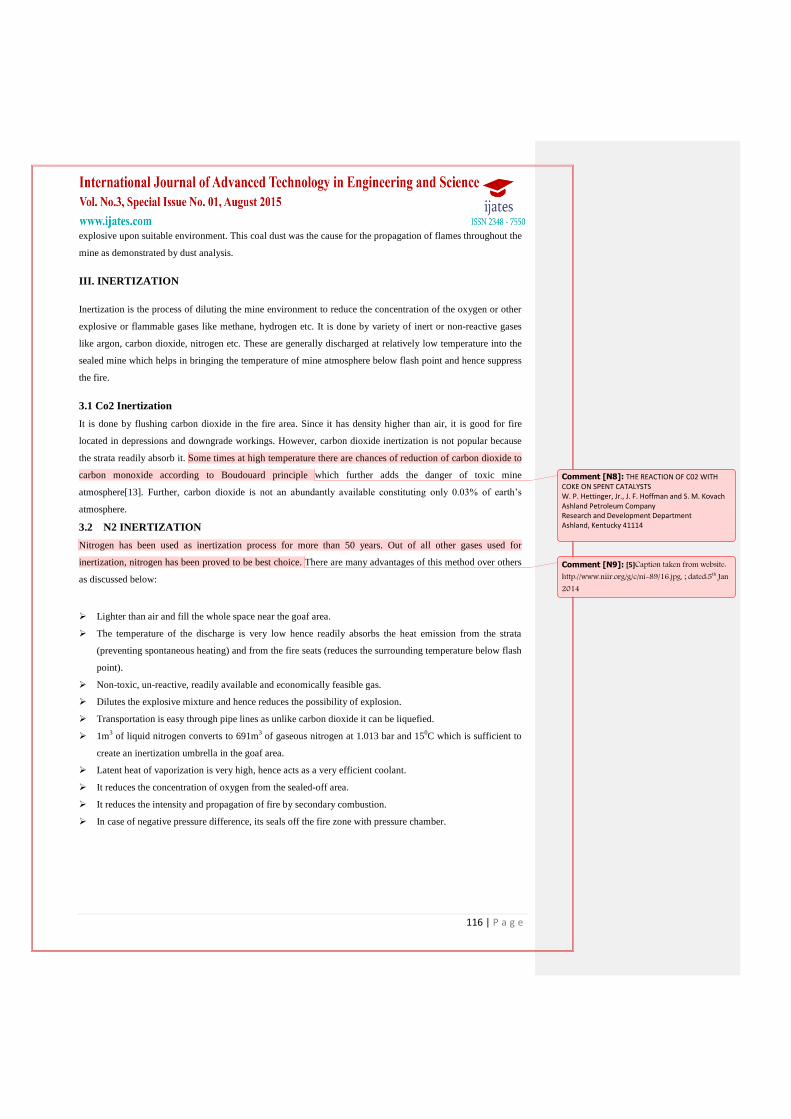
III. INERTIZATION
Inertization is the process of diluting the mine environment to reduce the concentration of the oxygen or other
explosive or flammable gases like methane, hydrogen etc. It is done by variety of inert or non-reactive gases
like argon, carbon dioxide, nitrogen etc. These are generally discharged at relatively low temperature into the
sealed mine which helps in bringing the temperature of mine atmosphere below flash point and hence suppress
the fire.
3.1 Co2 Inertization
It is done by flushing carbon dioxide in the fire area. Since it has density higher than air, it is good for fire
located in depressions and downgrade workings. However, carbon dioxide inertization is not popular because
the strata readily absorb it. Some times at high temperature there are chances of reduction of carbon dioxide to
carbon monoxide according to Boudouard principle which further adds the danger of toxic mine
atmosphere[13]. Further, carbon dioxide is not an abundantly available constituting only 0.03% of earth‘s
atmosphere.
3.2 N2 INERTIZATION
Nitrogen has been used as inertization process for more than 50 years. Out of all other gases used for
inertization, nitrogen has been proved to be best choice. There are many advantages of this method over others
as discussed below:
Lighter than air and fill the whole space near the goaf area.
The temperature of the discharge is very low hence readily absorbs the heat emission from the strata
(preventing spontaneous heating) and from the fire seats (reduces the surrounding temperature below flash
point).
Non-toxic, un-reactive, readily available and economically feasible gas.
Dilutes the explosive mixture and hence reduces the possibility of explosion.
Transportation is easy through pipe lines as unlike carbon dioxide it can be liquefied.
1m3 of liquid nitrogen converts to 691m
3 of gaseous nitrogen at 1.013 bar and 15
0C which is sufficient to
create an inertization umbrella in the goaf area.
Latent heat of vaporization is very high, hence acts as a very efficient coolant.
It reduces the concentration of oxygen from the sealed-off area.
It reduces the intensity and propagation of fire by secondary combustion.
In case of negative pressure difference, its seals off the fire zone with pressure chamber.
Comment [N8]: THE REACTION OF C02 WITH COKE ON SPENT CATALYSTS W. P. Hettinger, Jr., J. F. Hoffman and S. M. Kovach Ashland Petroleum Company Research and Development Department Ashland, Kentucky 41114
Comment [N9]: [5]Caption taken from website: http://www.niir.org/g/c/ni-89/16.jpg, ; dated:5th Jan 2014
117 | P a g e
IV. NITROGEN PRODUCTION METHODS
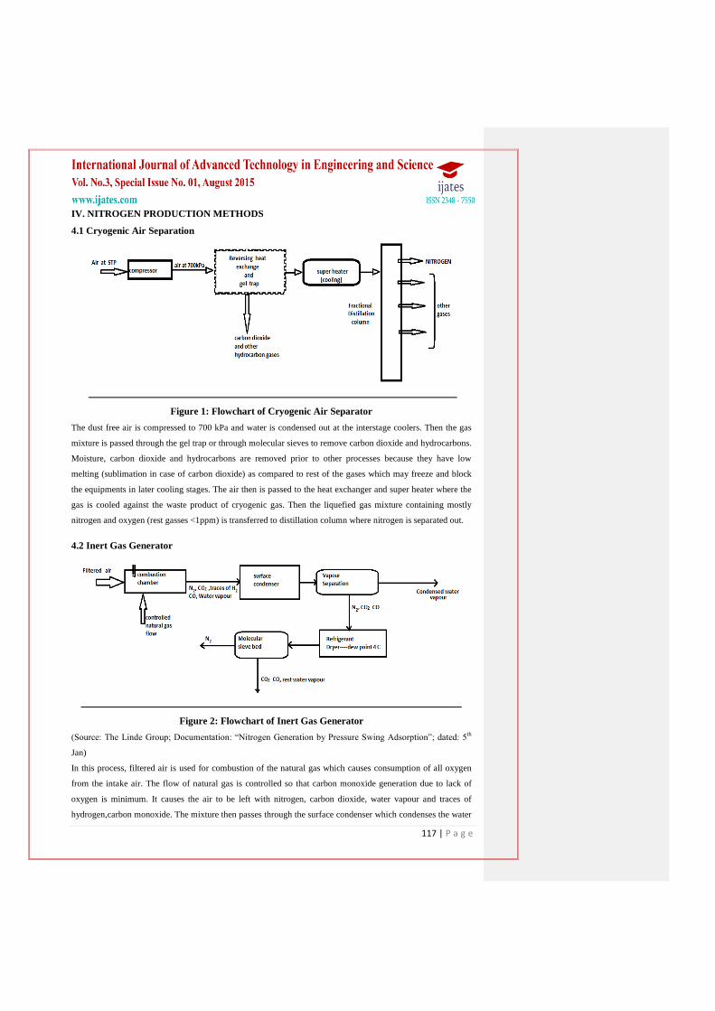
4.1 Cryogenic Air Separation
Figure 1: Flowchart of Cryogenic Air Separator
The dust free air is compressed to 700 kPa and water is condensed out at the interstage coolers. Then the gas
mixture is passed through the gel trap or through molecular sieves to remove carbon dioxide and hydrocarbons.
Moisture, carbon dioxide and hydrocarbons are removed prior to other processes because they have low
melting (sublimation in case of carbon dioxide) as compared to rest of the gases which may freeze and block
the equipments in later cooling stages. The air then is passed to the heat exchanger and super heater where the
gas is cooled against the waste product of cryogenic gas. Then the liquefied gas mixture containing mostly
nitrogen and oxygen (rest gasses <1ppm) is transferred to distillation column where nitrogen is separated out.
4.2 Inert Gas Generator
Figure 2: Flowchart of Inert Gas Generator
(Source: The Linde Group; Documentation: ―Nitrogen Generation by Pressure Swing Adsorption‖; dated: 5th
Jan)
In this process, filtered air is used for combustion of the natural gas which causes consumption of all oxygen
from the intake air. The flow of natural gas is controlled so that carbon monoxide generation due to lack of
oxygen is minimum. It causes the air to be left with nitrogen, carbon dioxide, water vapour and traces of
hydrogen,carbon monoxide. The mixture then passes through the surface condenser which condenses the water
118 | P a g e
vapours to liquid which is subsequently separated from the gas mixture. Then temperature is further reduced to
40C, the carbon dioxide and rest water vapour are removed using carbon molecular sieve. The gas coming out
of it is left with nitrogen.
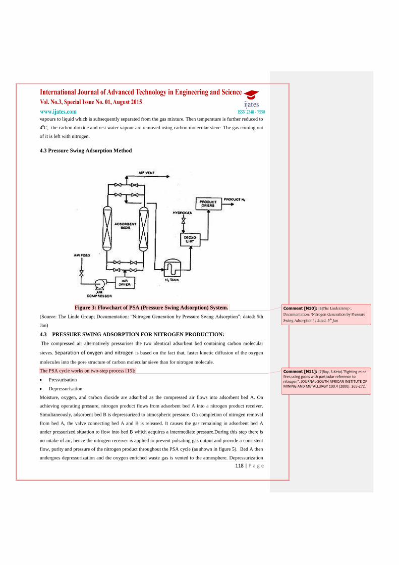
4.3 Pressure Swing Adsorption Method
Figure 3: Flowchart of PSA (Pressure Swing Adsorption) System.
(Source: The Linde Group; Documentation: ―Nitrogen Generation by Pressure Swing Adsorption‖; dated: 5th
Jan)
4.3 PRESSURE SWING ADSORPTION FOR NITROGEN PRODUCTION:
The compressed air alternatively pressurises the two identical adsorbent bed containing carbon molecular
sieves. Separation of oxygen and nitrogen is based on the fact that, faster kinetic diffusion of the oxygen
molecules into the pore structure of carbon molecular sieve than for nitrogen molecule.
The PSA cycle works on two-step process [15]:
Pressurisation
Depressurisation
Moisture, oxygen, and carbon dioxide are adsorbed as the compressed air flows into adsorbent bed A. On
achieving operating pressure, nitrogen product flows from adsorbent bed A into a nitrogen product receiver.
Simultaneously, adsorbent bed B is depressurized to atmospheric pressure. On completion of nitrogen removal
from bed A, the valve connecting bed A and B is released. It causes the gas remaining in adsorbent bed A
under pressurized situation to flow into bed B which acquires a intermediate pressure.During this step there is
no intake of air, hence the nitrogen receiver is applied to prevent pulsating gas output and provide a consistent
flow, purity and pressure of the nitrogen product throughout the PSA cycle (as shown in figure 5). Bed A then
undergoes depressurization and the oxygen enriched waste gas is vented to the atmosphere. Depressurization
Comment [N10]: [6]The LindeGroup ; Documentation: “Nitrogen Generation by Pressure Swing Adsorption” ; dated: 5th Jan
Comment [N11]: [7]Ray, S.Ketal,”Fighting mine fires using gases with particular reference to nitrogen”, JOURNAL-SOUTH AFRICAN INSTITUTE OF MINING AND METALLURGY 100.4 (2000): 265-272.

119 | P a g e
releases oxygen, carbon dioxide, and water vapor previously adsorbed during nitrogen production from
adsorbent bed A. At the same time, adsorbent bed B is brought to opera-tingpressure, and begins its nitrogen
production portion of the cycle.
Following nitrogen production, adsorbent bed B undergoes equalization and subsequent depressurization. The
cycle continues at the point where adsorbent bed A undergoes pressurization and adsorbent bed B is
depressurized.
Figure 4:Pressure Variation Demonstrating A: Pressure Equalization; B: Back Purge Step; C:
Nitrogen Production; D: Pressure Equalization; E: Depressurization with Respect to Time in
Adsorbent Vessel A (Absorber A) and Adsorbent Vessel B (Absorber B) (Source: Ray, S.Ketal
(2000))
V. NITROGEN CONCENTRATION VARIATION IN SEALED OFF AREAS
Further, the amount of gas to be pumped inside the fire site depends on the rate of air leakage into the fire zone.
For minimum gas requirement air leakage has to be minimized. The air leakage basically depends on the air
pressure difference in sealed and rest part of the mine. The pressure difference can be caused due to the
following [16]:
1. Pressure loss in ventilated mine working adjoining to the sealed area.
2. Buoyancy pressures that develop due to differential density of air in sealed and rest mine.
3. Barometric pressure variations.
Comment [N12]: [7]Ray, S.Ketal,”Fighting mine fires using gases with particular reference to nitrogen”, JOURNAL-SOUTH AFRICAN INSTITUTE OF MINING AND METALLURGY 100.4 (2000): 265-272.
Comment [N13]: [16] FAUCONNIER, C.J. and
MEYER, M.J.R. Conceptual Mathematical Models
for the
Injection of Nitrogen into Sealed Colliery Fires. J. S.
Afr. Inst. Min. Metall.
vol. 86, no. 3, March 1986. pp. 81–88.

120 | P a g e
Concentration of nitrogen to suppress fire in sealed-off area can be calculated when the target panel is
subjected to continuous unidirectional leakage and inflow of an external gas which may be methane due to
strata emission. The concentration of nitrogen after a time‗t‘ in the sealed panel subjected to above conditions
can be given by [17]:
1
Where & 2
‗T‘ is average temperature inside the panel. All the values are at temperature ‗T‘.
QL : air leakage rate (m3/s).
QN : rate of nitrogen injection (m3/s).
QG : inflow rate of external (m3/s).
N0 : initial nitrogen percentage in panel.
Na : nitrogen percentage in ambient air.
V : volume of sealed panel.
The above equation is valid only when:
1. The leakage rate as well as gas inflow rate is assumed to be constant.
2. QL and QG are reasonably accurate.
VI. CASE STUDIES
6.1 Tisco, Sujia Colliery, India
Large scale application of liquid N2 for controlling fires in various regions like Sujia Colliery, TISCO has
firmly established the usefulness of cryogenic N2 technology in controlling mine fires.
The following case study (adopted) demarcates successful implementation of previously described technique.
Sujia Colliery, TISCO is an underground coal mine in Dhanbad district of Jharkhand. Fires started in No. 13
and 14 seams due to contribution of multiple negative contributing factors including spontaneous combustion
of coal. As the first step of damage control, the fire in Nos. 13 and 14 seams of the mine were sealed off and
after continuing for several years, was broughtunder control by Pressure Balancing. Later on, in order to
meetproduction target and provide adequate ventilation at variousworking faces, mine management installed a
higher capacityfan (VF-3000) at pit No. 8 and also made several changes in theventilation network of the mine.
The change proved to be detrimental as it resulted in deterioration of condition of fire. This was because the
changes had resulted in pressure imbalance across the two affectedareas. Central Mining Research Institute
(CMRI), Dhanbad, India was designated to look into this grave problem which was affecting the overall
production of the mine apart from raising safety issues.After detailed assessment, dynamic balancing of
pressures across various regions and installation of a 500 m3/hr capacity N2 gas generator (PSA type) for fire
control was recommended. At most of the palaces, former recommendation incurred largely positive results.
However, some regions were still not mitigated but that was due to leakage of O2 in these regions. Taking into
account these results, nitrogen flushing was called upon and a 500m3/hr PSA N2 generator was installed. To
maintain an uninterrupted supply of N2 for further operations, an additional plant with similar technical
characteristics, but of larger capacity of 1000m3/hr was suggested to be installed. The first plant is showing
Comment [N14]: [17]ADAMUS, ALOIS,
HAJEK, LUBOMIR and POSTA, VACLAV. A
review of experiences on
the use of nitrogen in Czech coal mines. Proceeding
of the 7th US Mine Ventilation Symposium, 1995. pp. 237–241.
121 | P a g e
encouraging results yielding 99.3% purity of N2. In a total void area of 8 million m3, 7million m3 of N2 has
been injected to date.[18]
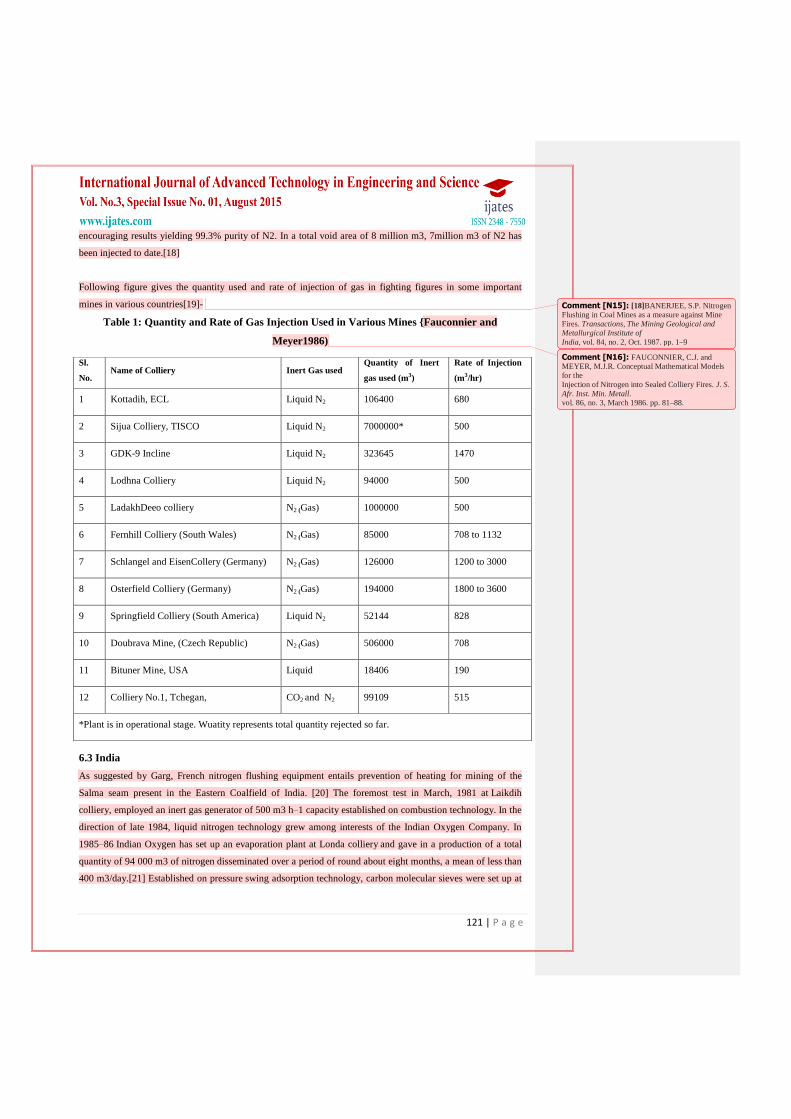
Following figure gives the quantity used and rate of injection of gas in fighting figures in some important
mines in various countries[19]-
Table 1: Quantity and Rate of Gas Injection Used in Various Mines {Fauconnier and
Meyer1986)
6.3 India
As suggested by Garg, French nitrogen flushing equipment entails prevention of heating for mining of the
Salma seam present in the Eastern Coalfield of India. [20] The foremost test in March, 1981 at Laikdih
colliery, employed an inert gas generator of 500 m3 h–1 capacity established on combustion technology. In the
direction of late 1984, liquid nitrogen technology grew among interests of the Indian Oxygen Company. In
1985–86 Indian Oxygen has set up an evaporation plant at Londa colliery and gave in a production of a total
quantity of 94 000 m3 of nitrogen disseminated over a period of round about eight months, a mean of less than
400 m3/day.[21] Established on pressure swing adsorption technology, carbon molecular sieves were set up at
Sl.
No. Name of Colliery Inert Gas used
Quantity of Inert
gas used (m3)
Rate of Injection
(m3/hr)
1 Kottadih, ECL Liquid N2 106400 680
2 Sijua Colliery, TISCO Liquid N2 7000000* 500
3 GDK-9 Incline Liquid N2 323645 1470
4 Lodhna Colliery Liquid N2 94000 500
5 LadakhDeeo colliery N2 (Gas) 1000000 500
6 Fernhill Colliery (South Wales) N2 (Gas) 85000 708 to 1132
7 Schlangel and EisenCollery (Germany) N2 (Gas) 126000 1200 to 3000
8 Osterfield Colliery (Germany) N2 (Gas) 194000 1800 to 3600
9 Springfield Colliery (South America) Liquid N2 52144 828
10 Doubrava Mine, (Czech Republic) N2 (Gas) 506000 708
11 Bituner Mine, USA Liquid 18406 190
12 Colliery No.1, Tchegan, CO2 and N2 99109 515
*Plant is in operational stage. Wuatity represents total quantity rejected so far.
Comment [N15]: [18]BANERJEE, S.P. Nitrogen Flushing in Coal Mines as a measure against Mine
Fires. Transactions, The Mining Geological and Metallurgical Institute of
India, vol. 84, no. 2, Oct. 1987. pp. 1–9
Comment [N16]: FAUCONNIER, C.J. and MEYER, M.J.R. Conceptual Mathematical Models
for the
Injection of Nitrogen into Sealed Colliery Fires. J. S.
Afr. Inst. Min. Metall. vol. 86, no. 3, March 1986. pp. 81–88.

122 | P a g e
the same mine in July, 1986; this implementation of molecular sieves was their foremost application in the
circumstances of mine safety context.[22]
Mass use of liquid nitrogen was caused in 1986 at the Godavarikhani No. 9 incline of Singareni
Collieries Company, Ltd., to fight a blazing underground waste fire.36 Close to 462 m3 of liquid nitrogen was
expended throughout from 11 April to 4 July, 1986. The liquid nitrogen was channelized to the colliery
through a mobile tanker of 8.4-m3 capacity and then directly shot in underground via seven boreholes to the
level 330 m below surface. The sealed off mine was unfolded within 55 days of closure, total ventilation was
launched in 93 days and production was rejuvenated in 109 days. The methods of liquid nitrogen flushing,
foaming nitrogen flushing and equipment like portable nitrogen generator (pressure swing adsorption nitrogen
generator) was employed during the Jhanjra project— curtailment of self-generated heating in a goaf of
longwall face AW1 in the R-VIIA seam of Jharia mine, Eastern Coalfields, Ltd., West Bengal37 (Fig. 9). The
foaming chemical compound and nitrogen foam generator machine were acquired from M/S Technovent,
Czech Republic. To render the foam 3–5% of foaming compound (detergent/protein based) was fused with 95–
97% water in the tank. The mixture was made to go through the foam generator, where gaseous nitrogen was
also made to go through at a pressure of 4–5 bars. The liquid mixture was altered into foam and channeled to
the caved goaf through a pipe established in the boreholes from the surface (to depth of the AW1 goaf, 103 m
below surface).
Figure 6: Liquid Nitrogen Flushing, Foaming Nitrogen Flushing and Portable PSA Nitrogen
Generator at Jhanjra Project, West Bengal, India. (Photograph by Vorác¢ek)
6.4 Great Britain
Nitrogen smothering has been used at Fern hill colliery. [23]On 24 July, 1962, a shot firing event ignited
methane and set coal on fire in the north main heading. The following day it was decided by the mine
management decided to seal off the area and the mine was closed for normal working. In a series of events
Comment [N17]: 20. Garg P. C. and Bhowmick P. C. Use of nitrogen flushing to spontaneous heating—proposals for a trial in an Indian mine. J. Minerals, Metals and Fuels, September 1978, 315–22. 21. Garg P. C. Development of nitrogen infusion technology for fighting and inhibition of fires. J. Minerals, Metals and Fuels, August 1987, 368–77, 394. 22. Adamus A. Experience of the use of nitrogen and foam technology in the Czech coal mines. In Proc. First International mine environment and ventilation symposium, Dhanbad, 11–12 December 2000, Appendix 68, 1–4.
Comment [N18]: [23] Vaughan-Thomas T. The use of nitrogen in controlling an underground fire at Fernhill colliery. Trans. Instn Min. Engrs, 123, March 1964, 311–27.

123 | P a g e
which followed and the futile attempts of balancing the pressures, nitrogen injection was finally called to
control the fire. Gaseous nitrogen at a rate of 50 000 ft3/h (1415 m3/h), at a purity of 99.5% was supplied.
Nitrogen injection started on 10 August, when the oxygen percentage in the fire area was 15.38%. After 24 hr
of injection, after 16 700 m3 nitrogen had been pumped in, the oxygen level had dropped to 10%. After a
further 36 hr, with a total of 53 000 m3 of gaseous nitrogen injected, the oxygen level had fallen to 7.37%.
From the concentration changes of gases within the fire area it was calculated that the volume of sealed-off
roadway inside the stopping was 11,300 m3, disregarding leakage. The rate of nitrogen flow varied from 550 to
12500 m3/hr throughout the operation period. To sum up, 2,400,000 m3 of gaseous nitrogen was supplied to
Fern hill colliery. [24] Following this effective utilization of Nitrogen inertization technique to control the
atmosphere of the sealed off areas, work had been resumed in areas near the region of fire seat, while doing
away with an explosion hazard.
VII. CONCLUSION
The use of nitrogen for inhibition, control and extinguishing underground fires, exclusively from 1960 was
universal due to its physical and chemical properties. For the last two decades, momentous progress, made
largely due to availability and cost effectiveness of nitrogen as compared to other options available in India,
like inert gases. It helps in protection of rescuers from fire and explosions, creating the opportunity to open
sealed off fire area, controlling spontaneous combustion in goaf of working panels. The following factor
considered before its use in underground fires:
a. Leakage factor should be taken into account for applications of nitrogen in sealed off fire areas in order to
also keep the N2 requirements minimum;
b. Dissipation of accumulated heat should take place in goaf areas of working panels to avoid spontaneous
heating; and
c. Regular thermo compositional monitoring should be carried out during after application of nitrogen in goaf
area to know the explosive behavior of gas mixture.
d. We also have arrived to few conclusive points:
e. Face ventilation can influence the effectiveness of nitrogen inertization;
f. Nitrogen inertization is generally found to be most effective injected on head gate side while on the tail gate
side, if injected, nitrogen travel mostly to the return airway and thus not an effective measure.
During the years 1980-90 the use of nitrogen to inertise the sealed off fire areas was at peak, thus being called
as ‗Golden Age‘. Extensive experiences of the use of nitrogen in mines for the last two decade in India have
shown that it is useful to combine this technology with other measures in the prevention and control of
subsurface fires.
REFERENCES
[1] Mitra D.K., Fires in Indian coal mines- An overview, Proc Nat Semin on Mine ventilation, safety and
Environment, 29-30 November, 2001, (CMRI, Dhanbad), 135-154.
[2] Singh, R. V. K., Acharya, A. K., &Dhar, B. B. (1994). Status of mine fire of Indian coal fields–An
Overview with suggestions. CMRI, Dhanbad, Inhouse report.
Comment [N19]: [24]Harris L. The use of nitrogen to control spontaneous combustion heatings. The Mining Engineer, June 1981, 883–92.

124 | P a g e
[3] Maiti, J., Khanzode, V. V., & Ray, P. K. (2009). Severity analysis of Indian coal mine accidents–a
retrospective study for 100 years. Safety science, 47(7), 1033-1042.
[4] Tomomura, M., Haga, T., Nogita, S., Ichihara, K., &Ishizu, T. (1988). U.S. Patent No. 4,746,332.
Washington, DC: U.S. Patent and Trademark Office.
[5] Banerjee, S.C., ―A Theoretical Design to the Determination of Risk Index of Spontaneous Fires in Coal
Mines‖, Journal of Mines, Metals and Fuels, 399-406, 1982.
[6] Banerjee, S.C., ―Spontaneous Combustion of Coal and Mine Fires‖, Oxford and IBH Publishing
Company, India, 1985.
[7] Goodarzi, F. and Gentzis, T., ―Geological Controls on the Self Burning of Coal Seams‖, D.C. Peters,
Ed., Geology in Coal Resource Utilization, TechBooks, Fairfax, Virginia, 1991.
[8] G¨uney, M., ―Oxidation and Spontaneous Combustion of Coal – Review of Individual Factors‖,
Colliery Guardian, 216, 105-110 and 137-143, 1968
[9] M¨unzner, H. und Peters, W., ―ZurKinetik der KohlenoxidationimTemperaturbereich 30-100◦C‖,
Brennstoff-Chemie, 12, 399-406, 1965.
[10] Postrzednik, S., Bialecki, R., Novak, A., Scholz, R. und Specht, E., ―ZurProblematik der
Selbsterwaermung fester Brennstoffe (1)‖, Erd¨ol-ErdgasKohle, Heft 2, 79-85, 1988.
[11] Ulery, J. P. (James P.); Explosion hazards from methane emissions related to geologic features in coal
mines; DHHS publication; no. (NIOSH) 2008-123; Information circular (National Institute for
Occupational Safety and Health); IC 9503
[12] Mohalik, N. K., et al. "Application of nitrogen as preventive and controlling subsurface fire—Indian
context." J SciInd Res India 64 (2005): 273-280.
[13] W. P. Hettinger et.al. Jr., J. F. Hoffman and S. M. Kovach, the reaction of CO2 with coke on spent
catalysts; Ashland Petroleum Company Research and Development Department Ashland, Kentucky
41114.
[14] http://www.niir.org/g/c/ni-89/16.jpg; dated: 5th Jan 2014.
[15] Ray, S.Ketal,‖Fighting mine fires using gases with particular reference to nitrogen‖,Journal-South
African Institute of Mining and Metallurgy 100.4 (2000): 265-272.
[16] Fauconnier, C.J. and Meyer, M.J.R. Conceptual Mathematical Models for the Injection of Nitrogen into
Sealed Colliery Fires. J. S. Afr. Inst. Min. Metall. vol. 86, no. 3, March 1986. pp. 81–88.
[17] Adamus, Alois, Hajek, Lubomir And Posta, Vaclav; ―A review of experiences on the use of nitrogen in
Czech coal mines‖; Proceeding of the 7th US Mine Ventilation Symposium, 1995. pp. 237–241.
[18] Banerjee, S. P. (1987). Nitrogen flushing in coal mines as a measure against mine fires. Transactions,
Mining Geological and Metallurgical Institute of India,84(supplement no. 2), 1-9.
[19] Fauconnier, C. J., & Meyer, M. J. R. (1986). Conceptual mathematical models for the injection of
nitrogen into sealed colliery fires. JS AfrInst Min Metall,86(supplement no. 3), 81-88.
[20] Garg P. C. and Bhowmick P. C. Use of nitrogen flushing to spontaneous heating—proposals for a trial
in an Indian mine. J. Minerals, Metals and Fuels, September 1978, 315–22.
[21] Garg P. C. Development of nitrogen infusion technology for fighting and inhibition of fires. J.
Minerals, Metals and Fuels, August 1987, 368–77, 394.

125 | P a g e
[22] Adamus A. Experience of the use of nitrogen and foam technology in the Czech coal mines. In Proc.
First International mine environment and ventilation symposium, Dhanbad,11–12 December 2000,
Appendix 68,1-4.
[23] Vaughan-Thomas T. The use of nitrogen in controlling an underground fire at Fernhill colliery.Trans.
Instn Min. Engrs, 123, March 1964, 311–27.
[24] Harris L. The use of nitrogen to control spontaneous combustion heatings.The Mining Engineer, June
1981, 883–92.