Embed Size (px)
Citation preview

1
Review of new ideas, innovation of
non-rocket propulsion systems for Space
Launch and Flight
(Part 1) by Alexander Bolonkin
New York 2010
2
Review Part 1d of non-Rocket PS 3 23 11
Review of new ideas, innovation of non-rocket
propulsion systems for Space Launch and Flight (Part 1) by Alexander Bolonkin C&R, NJIT <[email protected]> Abstract In the past years the author and other scientists have published a series of new methods which
promise to revolutionize the space propulsion systems, space launching and flight. These include
the cable propulsion system, circle propulsion system and space keeper, kinetic propulsion
system, gas-tube propulsion system, sliding rotary method, asteroid employment,
electromagnetic accelerator, Sun and magnetic sail, solar wind sail, radioisotope sail,
electrostatic space sail, laser beam propulsion system, kinetic anti-gravitator (repulsator), Earth-
Moon non-rocket and Earth-Mars non-rocket transport system, multi-reflective beam propulsion
system, electrostatic levitation, etc.
Some of them have the potential to decrease launch costs thousands of time, other allow to
change the speed and direction of space apparatus without the spending of fuel.
The author reviews and summarizes some revolutionary propulsion systems for scientists,
engineers, inventors, students and the public. Key words: Review, Non-rocket propulsion, non-rocket space launching, non-rocket space flight, cable
launch system, circle launch system, space keeper, kinetic propulsion system, gas-tube launch system,
sliding rotary method, asteroid employment, electromagnetic accelerator, Sun and magnetic sail, solar
wind sail, radioisotope sail, electrostatic space sail, laser beam propulsion system, kinetic anti-gravitator
(repulsator), Earth-Moon non-rocket and Earth-Mars non-rocket transport system, multi-reflective beam
propulsion system, electrostatic levitation, recombination engine, electronic sail, solar sail.
Introduction Brief History. People have long dreamed to reach the sky. The idea of building a tower high
above the Earth into the heavens is very old [1],[6]. The Greed Pyramid of Gaza in Egypt
constructed c.2570 BCE has a height 146 m. The writings of Moses, about 1450 BC, in Genesis,
Chapter 11, refer to an early civilization that in about 2100 BC tried to build a tower to heaven
out of brick and tar. This construction was called the Tower of Babel, and was reported to be
located in Babylon in ancient Mesopotamia. Later in chapter 28, about 1900 BC, Jacob had a
dream about a staircase or ladder built to heaven. This construction was called Jacob’s Ladder.
More contemporary writings on the subject date back to K.E. Tsiolkovski in his manuscript
“Speculation about Earth and Sky and on Vesta,” published in 1895 [2-3]. Idea of Space Elevator
was suggested and developed Russian scientist Yuri Artsutanov and was published in the Sunday
supplement of newspaper “Komsomolskaya Pravda” in 1960 [4]. This idea inspired Sir Arthur
Clarke to write his novel, The Fountains of Paradise, about a Space Elevator located on a
fictionalized Sri Lanka, which brought the concept to the attention of the entire world [5].
Rockets for military and recreational uses date back to at least 13th century China.
Wernher von Braun, at the time a young aspiring rocket scientist, joined the military (followed
by two former VfR members) and developed long-range weapons for use in World War II by
Nazi Germany. In 1943, production of the V-2 rocket began in Germany. It had an operational

3
range of 300 km (190 mi) and carried a 1,000 kg (2,200 lb) warhead, with an amatol explosive
charge. It normally achieved an operational maximum altitude of around 90 km (56 mi), but
could achieve 206 km (128 mi) if launched vertically.
After World War 2 the missile systems have received the great progress and achieved a
great success. But rocket system is very expensive. In end of 1990 the researchers begin to study
the non-rocket systems which promise to decrease the space launch and flight cost in hundreds
times. The pioneer of these researches professor Alexander Bolonkin published the first serious
book [1] in this field.
Current status of non-rocket space launch and flight systems. Over recent years
interference-fit joining technology including the application of space methods has become
important in the achievement of space propulsion system. Part results in the area of non-rocket
space launch and flight methods have been patented recently or are patenting now.
Professor Bolonkin made a significant contribution to the study of the different types of non-
rocket space launch and flight in recent years [1],[6]-[22] (1982-2011). Some of them are
presented in given review.
Cable Space Launcher is researched in [1, pp.39-58]; Circle Launcher and Space Keeper were
developed in [1, pp.59-82]; Kinetic Launcher and Kinetic Keeper were researched in [1, Ch.5, 9],
[9], [10]; Gas tube hypersonic launcher presented in [1, pp.125-146]; Earth-Moon cable transport
system was offered in [1, pp.147-156]; Earth-Mars cable transport system [1, pp.157-164];
Centrifugal space launchers were suggested in [1, pp.187-208, pp.223-244]; Asteroids as
propulsion system of space ships were published in [1, pp.209-222]; Multi-reflex propulsion
systems were researched in [1, pp.223-244]; Electrostatic Solar wind propulsion was developed
in [1, pp.245-270]; Electrostatic utilization of asteroids as space propulsion in [1, pp.271-280];
Electrostatic levitation is presented in [1. pp.281-302]; Guided solar sail and energy generator is
described in [1, pp.303-308]; Radioisotope space sail and electro-generator is presented in [1,
pp.309-316]; Electrostatic solar sail is researched in [1, pp. 317-326]; Recombination space jet
propulsion engine is described in [1, pp.327-340]; and Electronic sail is described in [1, pp.327-
340]. Some of these systems were developed in [2]-[23].
Significant scientific, interplanetary and industrial use did not occur until the 20th century,
when rocketry was the enabling technology of the Space Age, including setting foot on the
moon.
But rockets are very expensive and have limited possibilities. In the beginning 21th century the
researches of non-rocket launch and flight started [1], [5]-[8].Some of them are described in this
review.
Main types of Non-Rocket Space Propulsion System
Contents:
1. Cable Space Launcher
2. Circle Launcher and Space Keeper
3. Kinetic Launcher and Kinetic keeper
4. Gas tube hypersonic launcher
5. Earth-Moon cable transport system
6. Earth-Mars cable transport system
7. Centrifugal space launchers
8. Asteroids as propulsion system of space ships
9. Multi-reflex propulsion systems

4
10. Electrostatic Solar wind propulsion
11. Electrostatic utilization of asteroids as space propulsion
12. Electrostatic levitation
13. Guided solar sail and energy generator
14. Radioisotope space sail and electro-generator
15. Electrostatic solar sail
16. Recombination space jet propulsion engine
17. Electronic sail
1. Cable Space Launcher* A method and facilities for delivering payload and people into outer space are presented. This
method uses, in general, engines and a cable located on a planetary surface. The installation
consists of a space apparatus, power drive stations located along the trajectory of the apparatus,
the cable connected to the apparatus and to the power stations, and a system for suspending the
cable. The drive stations accelerate the apparatus up to hypersonic speed.
The estimations and computations show the possibility of making these projects a reality in a
short period of time (two project examples are given: a launcher for tourists and a launcher for
payloads). The launch will be very cheap at a projected cost of $1–$5 per pound. The cable is
made from cheap artificial fiber widely produced by modern industry. ----------------
*This chapter was presented as Bolonkin’s papers IAC-02-V.P.06, IAC-02-S.P.14 at World Space
Congress-2002, Oct. 10–19, Houston, TX, USA, and as variant No. 8057 at symposium “The Next 100
years”, 14–17 July 2003, Dayton, Ohio, USA; or see [1, pp.39-58].
Brief Description. The installation includes (see notations in Fig. 1.1): a cable; power drive
stations; winged space apparatus (space ship, missile, probe, projectile and so on); conventional
engines and flywheels; and a launching area (airdrome). Between drive stations the cable is
supported by columns. The columns can also hold additional cables for future launches and a
delivery system for used cable.
Fig. 1.1. a. Launcher for a crewed space ship with single cable. Notations: 1 – cable contains 3
parts: main part, outlet part, and directive part; 2 – power drive station; 3 – cable support
columns; 4 – winged space apparatus (space ship, missile, probe, projectile and so on); 5
5
– trajectory of space apparatus; 6 – engine. b. A fixed slope small launcher for
projectiles.
The installation works in the following way. All drive station start to run. The first power
station pulls the cable, 1, connected to the winged space apparatus. The apparatus takes off from
the start area and flies with acceleration along trajectory 5. When the apparatus reaches the first
drive station, this drive station disconnects from the cable and the next drive station continues the
apparatus acceleration, and so on. At the end of the distance, the winged apparatus has reached
hypersonic speed, disconnects from the cable, changes the horizontal acceleration into vertical
acceleration (while it is flying in the atmosphere) and leaves the Earth’s atmosphere.
. The power stations contain the engines. The engine can be any type, for example, gas turbines,
or electrical or mechanical motors. The power drive station has also an energy storage system
(flywheel accumulator of energy), a type transmission and a clutch. The installation can also
have a slope and launch a projectile at an angle to horizon (Fig. 1.1b).
2. Circle Launcher and Space Keeper*
The author proposes a new method and installation for flight in space. This method uses the
centrifugal force of a rotating circular cable that provides a means to launch a load into outer
space and to keep the stations fixed in space at altitudes at up to 200 km. The proposed
installation may be used as a propulsion system for space ships and/or probes. This system uses
the material of any space body for acceleration and changes to the space vehicle trajectory. The
suggested system may also be used as a high capacity energy accumulator.
The article contains the theory of estimation and computation of suggested installations and
four projects. Calculations include: a maximum speed given the tensile strength and specific
density of a material, the maximum lift force of an installation, the specific lift force in planet’s
gravitation field, the admissible (safe) local load, the angle and local deformation of material in
different cases, the accessible maximum altitudes of space cabins, the speed than a space ship
can obtain from the installation, power of the installation, passenger elevator, etc. The projects
utilize fibers, whiskers, and nanotubes produced by industry or in scientific laboratories. ------------------------
* Detail manuscript was presented as Bolonkin’s paper IAC-02-IAA.1.3.03 at the Would Space Congress-
2002, 10-19 October, Houston, TX, USA. The material is published in JBIS, vol. 56, No 9/10, 2003, pp.
314-327. See in [1, pp.59-82].
Short description of Circle Launcher.
The installation includes (Fig. 2.1): a closed-loop cable made from light, strong material (such
as artificial fibers, whiskers, filaments, nanotubes, composite material) and a main engine, which
rotates the cable at a fast speed in a vertical plane. The centrifugal force makes the closed-loop
cable a circle. The cable circle is supported by two pairs (or more) of guide cables, which
connect at one end to the cable circle by a sliding connection and at the other end to the planet’s
surface. The installation has a transport (delivery) system comprising the closed-loop load cables
(chains), two end rollers at the top and bottom that can have medium rollers, a load engine and a
load. The top end of the transport system is connected to the cable circle by a sliding connection;
the lower end is connected to a load motor. The load is connected to the load cable by a sliding
control connection.
6
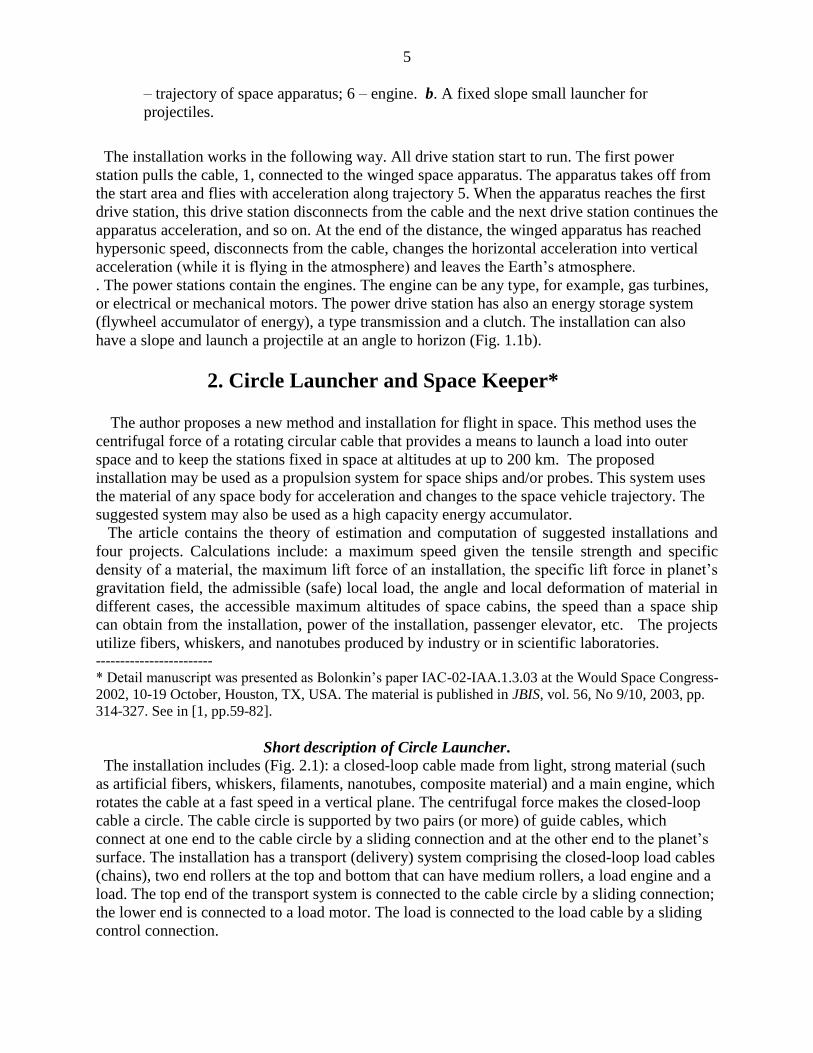
Fig. 2.1. Circle launcher (space station keeper) and space transport system. Notations are: 1 – cable
circle, 2 – main engine, 3 – transport system, 4 – top roller, 5 – additional cable, 6 – the load
(space station), 7 – mobile cabin, 8 – lower roller, 9 – engine of the transport system.
The installation can have the additional cables to increase the stability of the main circle, and
the transport system can have an additional cable in case the load cable is damaged.
The installation works in the following way. The main engine rotates the cable circle in the
vertical plane at a sufficiently high speed so the centrifugal force becomes large enough to it lifts
the cable and transport system. After this, the transport system lifts the space station into space.
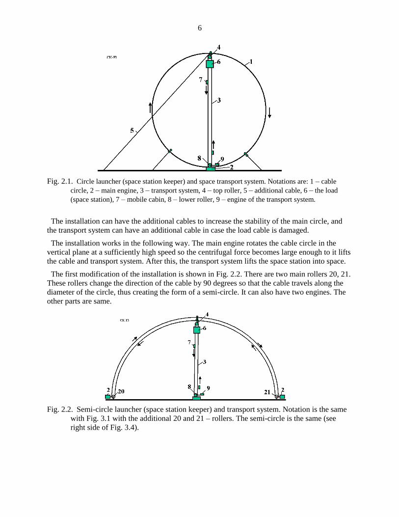
The first modification of the installation is shown in Fig. 2.2. There are two main rollers 20, 21.
These rollers change the direction of the cable by 90 degrees so that the cable travels along the
diameter of the circle, thus creating the form of a semi-circle. It can also have two engines. The
other parts are same.
Fig. 2.2. Semi-circle launcher (space station keeper) and transport system. Notation is the same
with Fig. 3.1 with the additional 20 and 21 – rollers. The semi-circle is the same (see
right side of Fig. 3.4).

7
The installation can be used for the launch of a payload to outer space (Fig. 2.3). The load is
connected to the cable circle by a sliding bearing through a brake. The load is accelerated by the
cable circle, lifted to a high altitude, and disconnected at the top of the circle (semi-circle).
The installation may also be used as transport system for delivery of people and payloads from
one place to another through space (Fig. 3.4 in [1]).
Fig. 2.3. Launching the space ship (probe) into space using cable semi-circle. 27 – load, 28 – vacuum
tube (option).
This system works in the following way. The installation has two cable circles, which move in
the opposite directions at the same speed. The space stations are connected to the cable circle
through the sliding connection. They can move along the circle in any direction when they are
connected to one of the cable circles through a friction clutch, transmission, gearbox, brake, and
engine, and can use the transport system in Figs. 2.1 and 2.2 for climbing to or descending from
the station. Because energy can be lost through friction in the connections, the energy transport
system and drive rollers transfer energy to the cable circle from the planet surface. The cable
circles are supported at a given position by the guide cables (see Project 2 in [1, Ch.3)]. No
towers for supporting the circle cable are needed.
The system can have only one cable (Figs. 2.1, 2.3).
Fig. 2.4. Cable circle around the Earth for 8–10 space objects. Notations are: 50 – double circle, 51 –
drive stations, 52 – guide cable, 53 – energy transport system, 54 – space station.
8
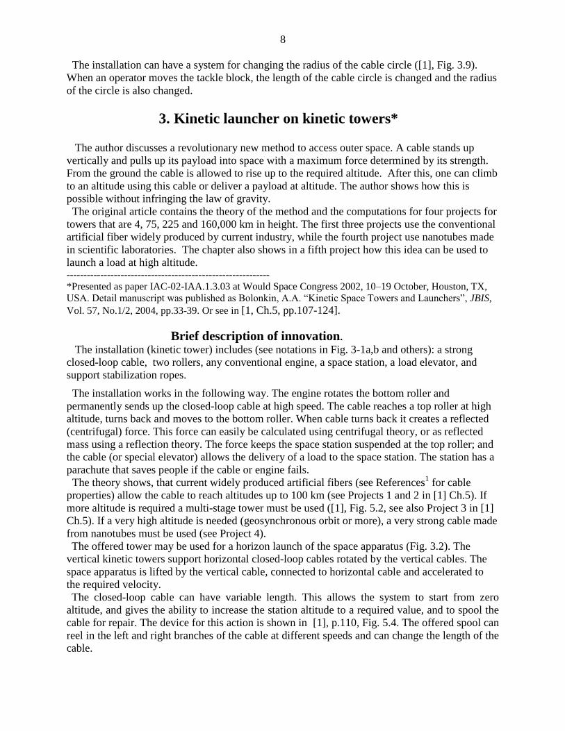
The installation can have a system for changing the radius of the cable circle ([1], Fig. 3.9).
When an operator moves the tackle block, the length of the cable circle is changed and the radius
of the circle is also changed.
3. Kinetic launcher on kinetic towers* The author discusses a revolutionary new method to access outer space. A cable stands up
vertically and pulls up its payload into space with a maximum force determined by its strength.
From the ground the cable is allowed to rise up to the required altitude. After this, one can climb
to an altitude using this cable or deliver a payload at altitude. The author shows how this is
possible without infringing the law of gravity.
The original article contains the theory of the method and the computations for four projects for
towers that are 4, 75, 225 and 160,000 km in height. The first three projects use the conventional
artificial fiber widely produced by current industry, while the fourth project use nanotubes made
in scientific laboratories. The chapter also shows in a fifth project how this idea can be used to
launch a load at high altitude. ------------------------------------------------------------
*Presented as paper IAC-02-IAA.1.3.03 at Would Space Congress 2002, 10–19 October, Houston, TX,
USA. Detail manuscript was published as Bolonkin, A.A. “Kinetic Space Towers and Launchers”, JBIS,
Vol. 57, No.1/2, 2004, pp.33-39. Or see in [1, Ch.5, pp.107-124].
Brief description of innovation.
The installation (kinetic tower) includes (see notations in Fig. 3-1a,b and others): a strong
closed-loop cable, two rollers, any conventional engine, a space station, a load elevator, and
support stabilization ropes.
The installation works in the following way. The engine rotates the bottom roller and
permanently sends up the closed-loop cable at high speed. The cable reaches a top roller at high
altitude, turns back and moves to the bottom roller. When cable turns back it creates a reflected
(centrifugal) force. This force can easily be calculated using centrifugal theory, or as reflected
mass using a reflection theory. The force keeps the space station suspended at the top roller; and
the cable (or special elevator) allows the delivery of a load to the space station. The station has a
parachute that saves people if the cable or engine fails.
The theory shows, that current widely produced artificial fibers (see References1 for cable
properties) allow the cable to reach altitudes up to 100 km (see Projects 1 and 2 in [1] Ch.5). If
more altitude is required a multi-stage tower must be used ([1], Fig. 5.2, see also Project 3 in [1]
Ch.5). If a very high altitude is needed (geosynchronous orbit or more), a very strong cable made
from nanotubes must be used (see Project 4).
The offered tower may be used for a horizon launch of the space apparatus (Fig. 3.2). The
vertical kinetic towers support horizontal closed-loop cables rotated by the vertical cables. The
space apparatus is lifted by the vertical cable, connected to horizontal cable and accelerated to
the required velocity.
The closed-loop cable can have variable length. This allows the system to start from zero
altitude, and gives the ability to increase the station altitude to a required value, and to spool the
cable for repair. The device for this action is shown in [1], p.110, Fig. 5.4. The offered spool can
reel in the left and right branches of the cable at different speeds and can change the length of the
cable.

9
Fig. 3.1. a. Offered kinetic tower: 1 – mobile closed loop cable, 2 – top roller of the tower, 3 – bottom
roller of the tower, 4 – engine, 5 – space station, 6 – elevator, 7 – load cabin, 8 – tensile element
(stabilizing rope). b. Design of top roller.
Fig. 3.2. a. Kinetic space installation with horizontally accelerated parts. b. 10 – accelerated missile.
4. Gas Tube Hypersonic Launcher*
The present review describes a hypersonic gas rocket, which uses tube walls as a moving
compressed air container. Suggested burn programs (fuel injection) enable use of the internal
tube components as a rocket. A long tube (up to 0.4–0.8 km) provides mobility and can be aimed
in water. Relatively inexpensive oxidizer and fuel are used (compressed air or gaseous oxygen
and kerosene). When a projectile crosses the Earth’s atmosphere at an angle more than 15o, loss
of speed and the weight of the required thermal protection system are small. The research shows
that the launcher can give a projectile a speed of up to 5–8 km/s. The proposed launcher can
deliver up to 85,000 tons of payloads to space annually at a cost of one to two dollars per pound
of payload. The launcher can also deliver about 500 tons of mail or express parcels per day over
continental distances and may be used as an energy station and accumulator. During war, this
launch system could deliver military munitions to targets thousands to tens of thousands of
kilometers away from the launch site.
------------------------
* This review is based on a paper presented at the 38th AIAA Propulsion Conference, 7–10 July
2002, Indianapolis, USA (AIAA-2002-3927) and the World Space Congress, 10–19 Oct. 2002,
Houston, USA (IAC-02-S.P.15). Detailed material is published as A.A.Bolonkin, “Hypersonic

10
Gas-Rocket Launcher of High Capacity”, JBIS, vol. 57, No. 5/6, 2004, pp. 162–172; Journal
Actual Problems of Aviation and Aerospace Systems, Kazan, 1 (15), pp. 45-69, 2003.
See also in [1, Ch.6, pp.125-146].
Description Fig. 4.1a shows a design of the tube of the suggested hypersonic gas-rocket system. The system
is made up of a tube, a piston with a fuel tank and payload, and nozzle connected to the piston,
and valves.
The tube rocket engine can be made without a special nozzle (Fig. 4.1b). In this case, the fuel
efficiency of the gas-rocket engine will decrease but its construction becomes simpler.
The tube may be placed into a frame (Fig. 4.1c). The frame is placed into water and connected to
a ship for mobility and aiming.
The launch sequence is as follows. First the movable piston with the fuel tank (containing liquid
fuel), and payload are loaded into the tube. The piston is held in place by the fasteners or closed
valve 17 (Fig. 4.1). The direction and angle of the launch tube are set.
Fig. 4.1. a - Space launcher with the gas rocket and rocket nozzle in the tube. The system comprises the
following: 1 – tube, 2 – payload (projectile), 3 – fuel tank, 4 – piston , 5 – fuel pipeline, 6 –
nozzle connected to piston, 7 – rocket air column, 8 – combustion chamber, 9 – injectors of the
combustion chamber, 12 – tube frame, 14 – additional injectors, 15 – lower tube injectors, 16 – air
pipeline, 17 – lower valve, 18 – upper valve, 19 – top valve, 20 – air lock, 21– gas pipe, 22 –
electric engines.
b - Space launcher with the gas rocket and no the rocket nozzle. c – Launcher in frame.
Valve 19 (Fig. 4.1) is closed and a vacuum (about 0.005 atm) is created in the launch tube space
above the payload/piston to reduce the drag imparted to the payload/piston as it moves along the
11
launch tube. The tube, of a length of 630 m and a diameter of 10 m, contains 61 tons of air at
atmospheric pressure. If this air is not removed, the payload must be decreased by the same value.
If air pressure is decreased down to 0.005 atm, the parasitic air mass is decreased to 300 kg. This
is an acceptable parasitic load.
Valve 17 is closed and an oxidizer (air, oxygen, or a mixture) is pumped into the space below
the payload/piston.
Liquid fuel (benzene, kerosene) is injected into the space below nozzle 6 through the launch
tube injectors (item 15, Fig. 4-1) and ignited. Valve 17 (Fig. 4-1) is opened. The hot combustion
gas expands and pushes the payload/piston system along the launch tube together with the air
column (item 7) between the piston and nozzle.
When the piston reaches the maximum gun speed (about 1 km/s), the compressed air column
begins to work as a rocket engine using one of the special injection fuel programs (see Reference
in [1, Ch.612
]).
As the payload/piston approaches the end of the launch tube, valve 19 is opened and the airlock
(item 20) begins to operate. After the payload/piston has left the launch tube, valve 18 closes the
end of the launch tube and re-directs the hot combustion gases down the bypass tube (item 21) to
various turbo-machines preparing compressed air for the next shot and electricity for customers.
If a high launch frequency is required, then internal tube water injectors are used to quickly cool
the launch tube.
After the payload/piston system leaves the launch tube, the payload (projectile) separates from
the piston and the empty fuel tank. The payload continues to fly along a ballistic trajectory. At
apogee, the payload may use a small rocket engine to reach orbit or to fly to any point on Earth.
The method by which the fuel is injected and ignited within the launch tube is critical to high-
speed (hypersonic) acceleration of the payload. The author has developed the five fuel injection
programs for the launch system12
.
In these programs the thrust (force) is constant at all times, which means that pressure and all
parameters in the rocket engine are constant. Parts of the programs have two steps. In the first step
the fuel is injected into compressed air at the lower part of the tube to support a constant pressure
and provide the initial acceleration of the rocket (together with air column Lr) to the velocity Vo.
In the second step the rocket engine begins to thrust and support the constant pressure and
temperature in the rocket combustion chamber. The result is that the thrust force of the gas-rocket
engine remains constant. In the reference article the author considered only a simplified model
([1, Fig. 6.1b]) when a rocket nozzle is absent.
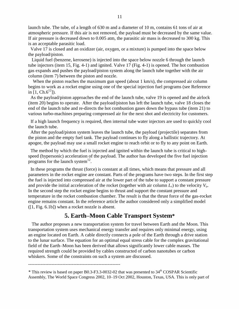
5. Earth–Moon Cable Transport System*
The author proposes a new transportation system for travel between Earth and the Moon. This
transportation system uses mechanical energy transfer and requires only minimal energy, using
an engine located on Earth. A cable directly connects a pole of the Earth through a drive station
to the lunar surface. The equation for an optimal equal stress cable for the complex gravitational
field of the Earth–Moon has been derived that allows significantly lower cable masses. The
required strength could be provided by cables constructed of carbon nanotubes or carbon
whiskers. Some of the constraints on such a system are discussed.
-----------------------------------------------------------
* This review is based on paper B0.3-F3.3-0032-02 that was presented to 34th COSPAR Scientific
Assembly, The World Space Congress 2002, 10–19 Oct 2002, Houston, Texas, USA. This is only part of
12
the original manuscript (one version of the system) presented to the WSC. This part of WSC manuscript
was published in as “Non-Rocket Earth–Moon Transport System”, in Advanced Space Research, Vol.
31, No. 11, pp. 2485–2490, 2003. See also [1, Ch.7, pp.147-155].
Brief Description.
The objectives of the proposed system are to provide an inexpensive means of travel between
the Earth and the Moon, to simplify space transportation technology, and to eliminate complex
hardware. The proposed Earth–Moon cable transport system is shown in Fig. 5.1. The system
consists of three cables: a main (central) cable, which supports the weight of the entire system,
and two closed-loop transport cables, which include a set (5–10) of cable chain links connected
sequentially to one other by rollers [1, Ch.73, 4
(see Fig.7.3a)]. The system is connected at the
Earth’s pole and to any position on the Moon’s surface that continually faces Earth. An engine
located on a planet (e.g. the Earth, but it could be the Moon) drives the cable transport system.
On the Earth, the cable is supported in the atmosphere by a winged device, which also
counteracts the rotation of the Earth. The transfer cable system transfers energy between load
cabins moved up and down, which requires the engine moving the cable system to overcome
only frictional forces.
An optimal (minimum mass, equal stress) variable diameter cable is defined for the main
tether. The main cable has a relatively large but variable cross-section area (diameter) because it
has to support the total system weight, which is several hundred times the load weight. In an
optimal main cable the cross-section area increases (for K = 2, about 20 times) in the altitude
range 0 – 150,000 km, is approximately constant in the range 150,000–380,000 km, and
decreases near the Moon’s surface, from 20,000 km to the surface.
The mass of the main cable is minimized because its diameter is variable along the distance
(see the next section for calculation of the main cable cross-section areas and mass). The
transport cables pull (move) the load cabins (one up, the other down) along the main cable. As
these are moveable parts, they must have constant diameter. If they had to carry a load the full
distance to the Moon, their mass would be very large. My concept separates the full distance into
sub-distances (5–10), with closed-loop links for every sub-distance connected by rollers. These
rollers transfer the transport cable movement from one link to another. In this case, the mass of
the transport cables is minimized because at every local length (sub-distance) the cable diameter
is determined by the local force. Total mass of the transport cable should be close to double the
mass of the main cable.
The load containers are connected to the transport cable. When containers come up to the
rollers, they pass the rollers, connect to the next link and continue their motion along the main
cable. The load (cabin) has special clamps to allow this transfer between the different diameter
cables in each link1. Most space payloads, like tourists, must be returned to Earth. When one
container is moved up, another container is moved down. The work of lifting equals the work of
descent, except for a small friction loss in the rollers. The transport system may be driven by a
conventional motor located at the Earth drive station, on a space station, or on the Moon. When
payloads are not being delivered into space, the system may be used to transfer mechanical
energy to the Moon. For example, the Earth drive station can rotate an electric generator on the
Moon.

13
Fig. 5.1. A conceptual Earth–Moon transportation system. One end is connected to the Earth’s pole.
the second end is connected to the Moon. Notation: 1 – the Earth; 2 – Earth’s atmosphere; 3 –
axis of Earth rotation; 4 – Earth Pole; 5 – Earth–Moon cable transport system in right position
(one extreme of the Moon’s position); 6 – Earth–Moon system in left position; 7 – air balloons; 8
– support wings; 9 – drive station; 10 – Moon.
The cable is supported in the Earth’s atmosphere by air balloons (around the pole) and
winged devices (far from the pole). The maximum speed of the system in the atmosphere is
about 190 m/sec at the maximum distance of 2700 km in the right-hand position of Fig. 5-1.
When the cable is located in the left-hand position, some wings may be out of the atmosphere
and not so effective.
The Moon’s orbit has eccentricity. Every 29 days the Moon’s distance from Earth changes by
about 50,000 km. Devices shown in Fig. 7.4 (in [1, Chapter 7]) must be used to change the
length (or link length) of the transport cables as the Earth–Moon distance changes. They may be
located at the Earth drive station, on a space station, in space, and/or on the Moon. The average
speed of a cable length change is about 40 m/s. As the Moon pulls the transport system, it may
be used to produce mechanical energy. If the cables can support 9 tons, the power can reach 1.8
million Watts. The cables rotate the electric generator and negligibly brake the Moon’s
movement.
6. Earth–Mars Cable Transport System*
The author offers and computes a new permanent cable transport system that links a pole of the
Earth with Mars orbit. This system connects Earth and Mars for 1–1.5 months every 1.7–2 years
when they are located at the nearest distance and allows the transfer of people and loads to Mars
and back. The system has many advantages because it uses a transport engine located on Earth,
but it also requires the high strength cable made from nanotubes. This work contains theory of an
optimal equal stress cable, that connects the Earth and Mars orbit, as well as computed
parameters of the suggested system.
-------------------------------
14
*Presented as paper BO.4-C3.4-0036-02 to The World Space Congress-2002 10–19 Oct. 2002, Houston,
Texas, USA. Detailed material was published in Actual Problems of Aviation and Aerospace Systems. No.
2 (16), vol. 8, 2003. See also [1, Ch.8, pp.157-164].
Brief Description
The review contains the theory and results of computation for a special project. This project
uses three cables (one main cable and two for driving loads) mass from artificial material:
whiskers, nanotubes, with the specific tensile strength (ratio of tensile stress to density) k = / =
20.10
7 (K = 20) or more. Nanotubes with the same or better parameters are available in scientific
laboratories. The theoretical limit of nanotubes of SWNT type is about k = 100.10
7 (K = 100).
A proposed centrifugal Mars cable transport system is shown in Figs. 6.1 and 6.2. The system
includes the optimal equal stress cable which has a length approximately equal to the minimum
distance of the Earth to Mars orbit. The installation has a transport system with chains connected
by rollers and two transport cables.
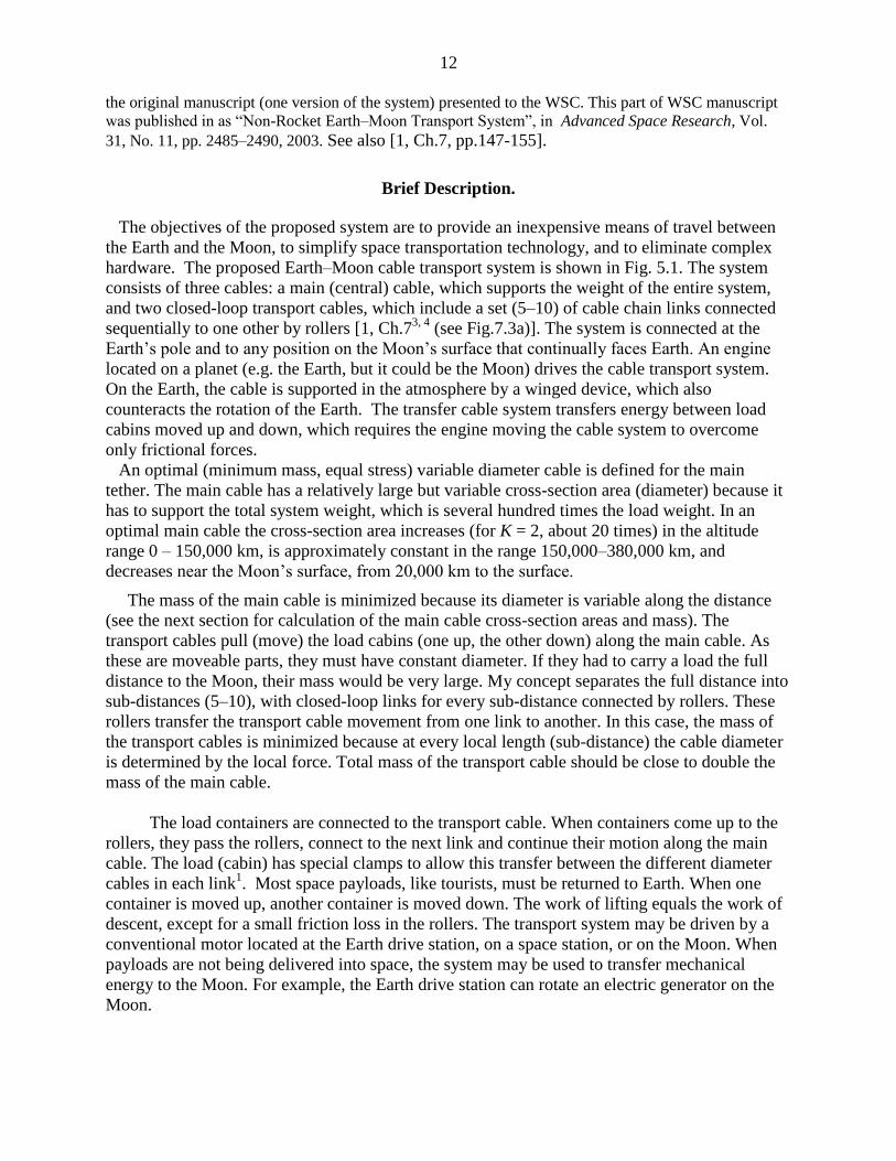
Fig. 6.1. The offered Earth–
Mars orbit Transport System.
a. Sun–Earth–Mars; b.
Earth–Mars; c. Connection
to Earth pole. Notations: 1–
Earth, 2 – Mars, 3 – Sun, 4 –
Earth pole, 5 – Earth–Mars
cable transport system in
right position, 6 – Earth–
Mars cable transport system
in left position, 7 – air
balloon, 8 – support wing, 9
– drive station, 10 – Earth
orbit, 11 – Mars orbit, 12 –
Earth atmosphere, 13 – axis
of Earth rotation.
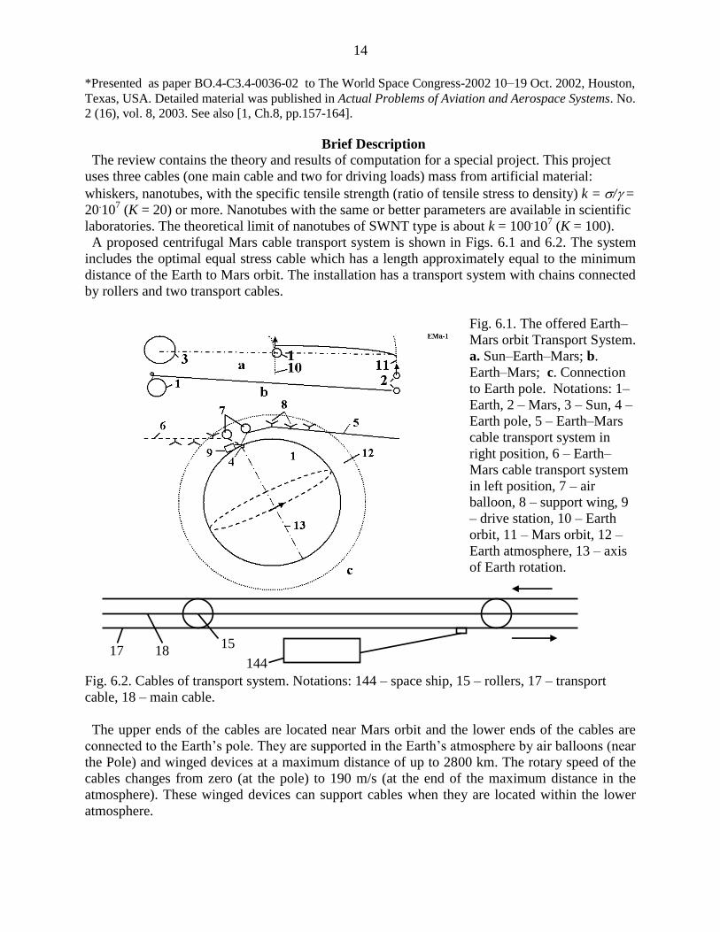
Fig. 6.2. Cables of transport system. Notations: 144 – space ship, 15 – rollers, 17 – transport
cable, 18 – main cable.
The upper ends of the cables are located near Mars orbit and the lower ends of the cables are
connected to the Earth’s pole. They are supported in the Earth’s atmosphere by air balloons (near
the Pole) and winged devices at a maximum distance of up to 2800 km. The rotary speed of the
cables changes from zero (at the pole) to 190 m/s (at the end of the maximum distance in the
atmosphere). These winged devices can support cables when they are located within the lower
atmosphere.
15 144
17 18
15
The installation would have a device that allows the length of the cables to be changed. The
device would consist of a spool, motor, brake, transmission, and controller. The facility could
have mechanisms for delivering people and payloads to Mars and back using the suggested
transport system.
The delivery devices include: containers (passenger cabins, space ships, etc.), cables, motors,
brakes, and controllers.
The space cabin can temporarily land on the surface of the Mars for loading and performing
research. The space cabin has a small rocket engine for maneuvering and landing on the surface
of Mars.
Every two years Mars comes within a minimum distance from Earth. For about 1–1.5 months
the cable transport system (CTS) can be used to deliver people and loads to Mars. The space ship
moves in advance to the upper end of the CTS, then when Mars arrives, the vehicles land on its
surface and the people work on for Mars 1–1.5 months; afterwards the space ships return to
Earth. While living on Mars, the people can fly from one place to another with speeds of about
230 m/s (including Mars round trip at low altitude) in their space cabin (ship). Exploring using
the CTS would not require rocket fuel.
7. Centrifugal Space Launcher*
This manuscript describes a method and devices that provides a repulsive (repel, push, opposed
to gravitation) force between given bodies. The basic concept is that a strong, heavy cable is
projected upwards using a motorized wheel on the ground. The upward momentum of the cable
is transferred to the apparatus by means of a pulley/roller mechanism, which sends the cable
back down to the motor. The momentum transferred from the cable to the apparatus produces a
push force which can suspend the apparatus in the air or lift it. There is an equal and opposite
force on the motorized wheel on the ground. The push force can be great (up to tens of tons) and
operate over long distances (up to hundreds of kilometers). This force produces great
accelerations and velocities of given bodies (vehicles).
-----------------
*The main idea of this Chapter was presented as IAC-02-IAA.1.3.03, 53rd International
Astronautical Congress. The World Space Congress – 2002, 10–19 Oct. 2002, Houston, Texas,
USA, and the full manuscript accepted as AIAA-2005-4504, 41 Propulsion Conference, 10–12
July, 2005, Tucson, Arizona, USA. See also [1, Ch.10, pp.187-206].
Description of Innovative Launcher
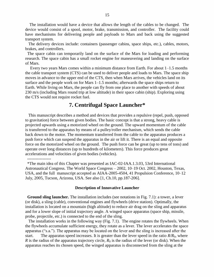
Ground sling launcher. The installation includes (see notations in Fig. 7.1): a tower, a lever
(or disk), a sling (cable), conventional engines and flywheels (drive station). Optimally, the
installation is located on a mountain (high altitude) to reduce air drag on the sling and apparatus
and for a lower slope of initial trajectory angle. A winged space apparatus (space ship, missile,
probe, projectile, etc.) is connected to the end of the sling.
The installation works in the following way (Fig. 7.1). The engine rotates the flywheels. When
the flywheels accumulate sufficient energy, they rotate as a lever. The lever accelerates the space
apparatus (“s.a.”). The apparatus may be located on the lever and the sling is increased after the
start. The apparatus speed increases. It is greater than the lever speed in the ratio R/R0, where
R is the radius of the apparatus trajectory circle, R0 is the radius of the lever (or disk). When the
apparatus reaches its chosen speed, the winged apparatus is disconnected from the sling at the
16
desired point of the circle. While the winged apparatus is flying in the atmosphere, it can
increase its slope and correct its trajectory. If the apparatus has a hypersonic (supersonic) form,
the speed loss is small13
.
Fig. 7.1. Sling rotary launcher. a) launcher located on mountain, b) top view of installation, c) acting
forces, d) side view. Notations: 1 – tower, 2 – lever or disk, 3 – engine, 4 – sling, 5 – space
apparatus (s.a.), 6 – circular launch trajectory, 7 – point of disconnection, 8 – direction of launch,
11 – centrifugal force of space apparatus, 12 – drag of s.a., 13 – speed of s.a., 14 – centrifugal force
of sling, 15 – drag of sling, 16 – lever force.
17
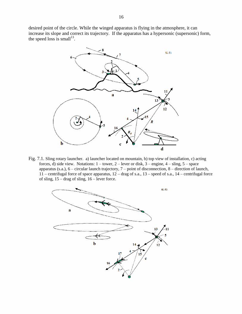
Fig. 7.2. Launching a space ship using aircraft. a) slinging slope start, b) upper start, c) installation
forces.
The offered launcher is different from conventional centrifugal catapults, which have a
projectile in a lever. This launcher has a long sling and the projectile is in the sling. The sling
increases the lever speed many times and decreases the mass of the lever. Conventional catapults
made from nanotubes have a huge mass and requires gigantic energy to work. This sling is also
made from nanotubes (for space speed), but its mass is small.
If the circle is parallel to the Earth’s surface, the winged apparatus disconnects from the cable,
converts the linear and centrifugal acceleration into vertical acceleration (while it is flying in the
atmosphere) and leaves the Earth’s atmosphere.
The power station houses the engine. It can be any engine, for example, a gas turbine, or an
electrical or mechanical motor. The power drive station also has an energy storage system
(flywheel accumulator of energy), a transmission drive train and a clutch mechanism.
The installation can be set on a slope, and launch a projectile at an angle to the horizon (Fig.
7.1).
The attained speed may be up to eight or more km/s (see project 2 below). If the planet does
not have an atmosphere, a small installation (with a small lever) can give the projectile a very
high speed, limited only by the power of the engine and the strength of the sling.
On the Earth’s surface the launcher can be located under a special cover (or in a tube) in a
vacuum.
Aircraft sling launcher. Another design of this sling launcher is presented in Figs. 7.2. A small
spacecraft (1 – 2 tons) is connected to a large, high-speed aircraft. The aircraft flies in a circle,
increasing the sling length and accelerating the ship to high speed. The attained speed depends
largely on the specific strength of the sling, the maximum aircraft speed and the thrust of the
aircraft. For large existing aircraft operating in the atmosphere, the launch speed may reach up 2
km/s. This is enough for the X-prize flight, reaching an altitude of up to 100 km and sufficient
for a spaceship for tourists (see projects 3–4 below).
Advantages. The suggested launch cable system has advantages compared to the current rocket
systems, as follows:
1. The sling launcher is many times less expensive than modern rocket launch systems.
No expensive rockets are needed. Only motor and cable are required.
2. The sling launcher reduces the delivery cost by several thousand times (to as low as $5 to
$10 per pound). (No rocket, cheaper fuel.)
3. The sling launcher could be constructed within one to two years. The aircraft sling launcher
requires only a cable and a spaceship. Modern rocket launch systems require many years
for R&D and construction.
4. The sling launcher does not require high technology and can be made by any non-industrial
country.
5. Rocket fuel is expensive. The ground sling launcher can use the cheapest sources of
energy, such as wind, water, or nuclear power, or the cheapest fuels such as gas, coal, peat,
etc., because the engine is located on the Earth’s surface. Flywheels may be used as an
accumulator of energy.
6. It is not necessary to have highly qualified personnel, such as rocket specialists with high
salaries.
7. The fare for space tourists would be small.

18
8. There is no pollution of the atmosphere from toxic rocket gas.
9. Thousands of tons of useful payloads can be launched annually.
Shortcomings of sling space launchers:
1. The need for a very strong sling (cable), made from carbon whiskers or still-to-be
manufactured long nanotubes.
2. The Earth ground sling launcher may be used only for robust loads because high centrifugal
acceleration is imposed on the payload. Such payloads normally account for 70–80% of
space payloads.
Cable (sling) discussion. The experimental and industrial fibers, whiskers, and nanotubes are
considered in [1], Chapters 1–2.
The reader can find a more complete cable discussion of cable and cable characteristics in [1],
Ch.10, the References3–13, 17–20.
8. Asteroids as Propulsion System of Space Ships*
The purpose of this section is to draw attention to the idea of sling rotary launchers. This idea
allows the building of inexpensive new space launcher systems, to launch missiles, projectiles,
and space apparatus, and to use many types of energy. This chapter describes the possibilities of
this method and the conditions which influence its efficiency. Included are four projects: a non-
rocket sling projectile launcher, a space sling launcher, a spaceship for launching using
conventional supersonic, and a space ship using subsonic aircraft. The last two only require low-
cost cable made from artificial fiber, using whiskers that are produced in industry now or
increasingly perfected nanotubes that are being created in a scientific laboratories. ---------------------
*The detailed work was presented as AIAA-2005-4035 at the 41 Propulsion Conference, 10–12 July,
2005, Tucson, Arizona, USA. See also [1, Ch.11, pp. 209-222].
Introduction.
There are many small solid objects in the Solar System called asteroids. The vast majority are
found in a swarm called the asteroid belt, located between the orbits of Mars and Jupiter at an
average distance of 2.1 to 3.3 astronomical units (AU) from the Sun. Scientists know of
approximately 6,000 large asteroids of a diameter of 1 kilometer or more, and of millions of
small asteroids with a diameter of 3 meters or more. Ceres, Pallas, and Vesta are the three largest
asteroids, with diameters of 785, 110 and 450 km (621, 378, and 336 miles), respectively. Others
range all the way down to meteorite size. In 1991 the Galileo probe provided the first close-up
view of the asteroid Caspra; although the Martian moons (already seen close up) may also be
asteroids, captured by Mars. There are many small asteroids, meteorites, and comets outside the
asteroid belt. For example, scientists know of 1,000 asteroids of diameter larger than one
kilometer located near the Earth. Every day 1 ton meteorites with mass of over 8 kg fall on the
Earth. The orbits of big asteroids are well known. The small asteroids (from 1 kg) may be also
located and their trajectory can be determined by radio and optical devices at a distance of
hundreds of kilometers.
Radar observations enable to discern of asteroids by measuring the distribution of echo power
in time delay (range) and Doppler frequency. They allow a determination of the asteroid
trajectory and spin and the creation of an asteroid image.
19
Most planets, such as Mars, Jupiter, Saturn, Uranus, and Neptune have many small moons that
can be used for the proposed space transportation method.
There are also the asteroids located at the stable Lagrange points of the Earth–Moon system.
These bodies orbit with the same speed as Jupiter, and might be very useful for propelling
spacecraft further out into the solar system. Comets may also be useful for propulsion once a
substantial spacecraft speed is obtained. It seems likely that the kinetic and rotational energy of
both comets and asteroids will eventually find application in space flight.
Most asteroids consist of carbon-rich minerals, while most meteorites are composed of stony-
iron.
The present idea [1]6–8
is to utilize the kinetic energy of asteroids, comets, meteorites, and
space debris to change the trajectory and speed of space ships (probes). Any space bodies more
than 10% of a ship’s mass may be used, but here mainly bodies with a diameter of 2 meters (6
feet) or larger are considered. In this case the mass (20–100 tons) of the space body (asteroid) is
some 10 times more than the mass of probe (1 ton, 2000 lb) and the probe mass can be
disregarded. Connection Method
The method includes the following main steps:
(a) Finding an asteroid using a locator or telescope (or looking in catalog) and determining its
main parameters (location, mass, speed, direction, rotation); selecting the appropriate
asteroid; computing the required position of the ship with respect to the asteroid.
(b) Correcting the ship’s trajectory to obtain the required position; convergence of the ship
with the asteroid.
(c) Connecting the space apparatus (ship, station, and probe) to the space body (planet,
asteroid, moon, satellite, meteorite, etc.) by a net, anchor, and a light strong rope (cable),
when the ship is at the minimum distance from the asteroid.
(d) Obtaining the necessary position for the apparatus by moving around the space body and
changing the length of the connection rope.
(e) Disconnecting the space apparatus from the space body; spooling the cable.
The equipment required to change a probe (spacecraft) trajectory includes:
(a) A light strong cable (rope).
(b) A device to measure the trajectory of the spacecraft with relative to the space body.
(c) A device for spacecraft guidance and control.
(d) A device for the connection, delivery, control, and disconnection and spooling of the
rope.
Description of Utilization
The following describes the general facilities and process for a natural space body (asteroid,
comet, meteorite, or small planet) with a small gravitational force to change the trajectory and
speed of a space apparatus.
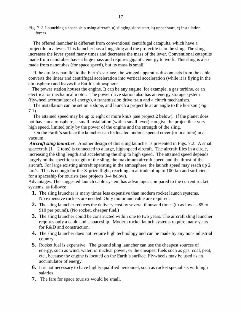
Figs. 8.1a,b,c show the preparations for using a natural body to change the trajectory of the
space apparatus; for example, the natural space body 2, which is moving in the same direction as
the apparatus (perpendicular to the sketch, Fig. 8.1a). The ship wants to make a maneuver
(change direction or speed) in plane 3 (perpendicular to the sketch), and the position of the
apparatus is corrected and moved into plane 3. It is assumed that the space body has more mass
than the apparatus.
20
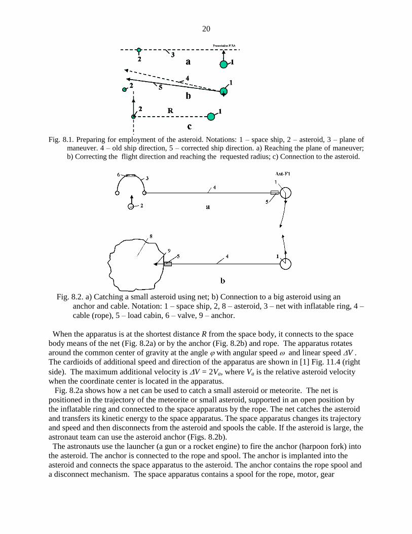
Fig. 8.1. Preparing for employment of the asteroid. Notations: 1 – space ship, 2 – asteroid, 3 – plane of
maneuver. 4 – old ship direction, 5 – corrected ship direction. a) Reaching the plane of maneuver;
b) Correcting the flight direction and reaching the requested radius; c) Connection to the asteroid.
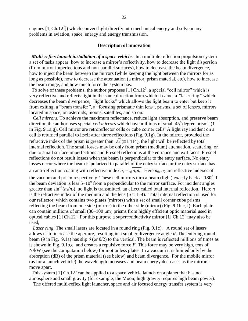
Fig. 8.2. a) Catching a small asteroid using net; b) Connection to a big asteroid using an
anchor and cable. Notation: 1 – space ship, 2, 8 – asteroid, 3 – net with inflatable ring, 4 –
cable (rope), 5 – load cabin, 6 – valve, 9 – anchor.
When the apparatus is at the shortest distance R from the space body, it connects to the space
body means of the net (Fig. 8.2a) or by the anchor (Fig. 8.2b) and rope. The apparatus rotates
around the common center of gravity at the angle with angular speed and linear speed V .
The cardioids of additional speed and direction of the apparatus are shown in [1] Fig. 11.4 (right
side). The maximum additional velocity is V = 2Va, where Va is the relative asteroid velocity
when the coordinate center is located in the apparatus.
Fig. 8.2a shows how a net can be used to catch a small asteroid or meteorite. The net is
positioned in the trajectory of the meteorite or small asteroid, supported in an open position by
the inflatable ring and connected to the space apparatus by the rope. The net catches the asteroid
and transfers its kinetic energy to the space apparatus. The space apparatus changes its trajectory
and speed and then disconnects from the asteroid and spools the cable. If the asteroid is large, the
astronaut team can use the asteroid anchor (Figs. 8.2b).
The astronauts use the launcher (a gun or a rocket engine) to fire the anchor (harpoon fork) into
the asteroid. The anchor is connected to the rope and spool. The anchor is implanted into the
asteroid and connects the space apparatus to the asteroid. The anchor contains the rope spool and
a disconnect mechanism. The space apparatus contains a spool for the rope, motor, gear

21
transmission, brake, and controller. The apparatus may also have a container for delivering a
load to the asteroid and back (Fig. 8.2b). One possible design of the space anchor is shown in [1,
Fig. 11.3]. The anchor has a body, a rope, a cumulative charge (shared charge), the rocket
impulse (explosive) engine, the rope spool and the rope keeper. When the anchor strikes the
asteroid surface the cumulative charge burns a deep hole in the asteroid and the rocket-impulse
engine hammers the anchor body into the asteroid. The anchor body pegs the catchers into the
walls of the hole and the anchor’s strength keeps it attached to the asteroid. When the apparatus
is to be disconnected from the asteroid, a signal is given to the disconnect mechanism.
If the asteroid is rotated with angular speed , its rotational energy can be used for increasing
the velocity and changing the trajectory of the space apparatus. The rotary asteroid spools the
rope on its body. The length of the rope is decreased, but the apparatus speed is increased (see a
momentum theory in physics).
The ship can change the length of the cable. When the radius decreases, the linear speed of the
apparatus increases; conversely, when the radius increases the apparatus speed decreases. The
apparatus can obtain energy from the asteroid by increasing the length of the rope.
The computations and estimations show the possibility of making this method a reality in a
short period of time.
An abandoned space vehicle or large piece of space debris in Earth orbit can also be used to
increase the speed of the new vehicle and to remove the abandoned vehicle or debris from orbit.
9. Multi-reflex Propulsion Systems for Space and Air Vehicles and
Energy Transfer for Long Distance*
The purpose of this article is to draw attention to the revolutionary idea of light multi-reflection.
This idea allows the design of new engines, space and air propulsion systems, storage systems
(for a beam or solar energy), transmission of energy (over millions of kilometers), creation of
new weapons, etc. This method and the main innovations were offered by the author in 1983 in
the former USSR. Now the author shows the immense possibilities of this idea in many fields of
engineering – astronautics, aviation, energy, optics, direct conversion of light (laser beam)
energy to mechanical energy (light engine), to name a few. This chapter considers the multi-
reflex propulsion systems for space and air vehicles and energy transmission over long distances
in space.
--------------------------
* A detailed manuscript was published by A.A. Bolonkin, JBIS, Vol. 57, No. 11/12. 2004, pp.
379–390, 2004. See also [1, Ch.12, pp.223-244].
Introduction
The reflection of light is the most efficient method to use for a propulsion system. It gives the
maximum possible specific impulse (light speed is 3.10
8 m/s). The system does not expend mass.
However, the light intensity in full reflection is very small, about 0.610–6
kg/ kW. In 1983 the
author suggested the idea of increasing the light intensity by a multi-reflex method (multiple
reflection of the light beam) and he offered some innovations to dramatically decrease the losses
in mirror reflection (including a cell mirror and reflection by a super–conducting material). This
allows the system to make some millions of reflections and to gain some Newtons of thrust per
kW of beam power. This allows for the design of many important devices (in particular, beam
22
engines [1, Ch.12
7]) which convert light directly into mechanical energy and solve many
problems in aviation, space, energy and energy transmission.
Description of innovation
Multi-reflex launch installation of a space vehicle. In a multiple reflection propulsion system
a set of tasks appear: how to increase a mirror’s reflectivity, how to decrease the light dispersion
(from mirror imperfections and non-parallel surfaces), how to decrease the beam divergence,
how to inject the beam between the mirrors (while keeping the light between the mirrors for as
long as possible), how to decrease the attenuation (a mirror, prism material, etc), how to increase
the beam range, and how much force the system has.
To solve of these problems, the author proposes [1] Ch.125, a special “cell mirror” which is
very reflective and reflects light in the same direction from which it came, a “laser ring” which
decreases the beam divergence, “light locks” which allows the light beam to enter but keep it
from exiting, a “beam transfer”, a “focusing prismatic thin lens“, prisms, a set of lenses, mirrors
located in space, on asteroids, moons, satellites, and so on.
Cell mirrors. To achieve the maximum reflectance, reduce light absorption, and preserve beam
direction the author uses special cell mirrors which have millions of small 45o degree prisms (1
in Fig. 9.1a,g). Cell mirror are retroreflector cells or cube corner cells. A light ray incident on a
cell is returned parallel to itself after three reflections (Fig. 9.1g). In the mirror, provided the
refractive index of the prism is greater than 2 (1.414), the light will be reflected by total
internal reflection. The small losses may be only from prism (medium) attenuation, scattering, or
due to small surface imperfections and Fresnel reflections at the entrance and exit faces. Fresnel
reflections do not result losses when the beam is perpendicular to the entry surface. No entry
losses occur where the beam is polarized in parallel of the entry surface or the entry surface has
an anti-reflection coating with reflective index .201 nnn Here n0, n2 are reflective indexes of
the vacuum and prism respectively. These cell mirrors turn a beam (light) exactly back at 180o if
the beam deviation is less 5–10o from a perpendicular to the mirror surface. For incident angles
greater than sin–1
(n1/n2), no light is transmitted, an effect called total internal reflection. Here n
is the refractive index of the medium and the lens (n ≈ 1–4). Total internal reflection is used for
our reflector, which contains two plates (mirrors) with a set of small corner cube prisms
reflecting the beam from one side (mirror) to the other side (mirror) (Fig. 9.1b,c, f). Each plate
can contain millions of small (30–100 μm) prisms from highly efficient optic material used in
optical cables [1] Ch.129. For this purpose a superconductivity mirror [1] Ch.12
5 may also be
used,
Laser ring. The small lasers are located in a round ring (Fig. 9.1c). A round set of lasers
allows us to increase the aperture, resulting in a smaller divergence angle θ. The entering round
beam (9 in Fig. 9.1a) has slip θ (or θ/2) to the vertical. The beam is reflected millions of times as
is shown in Fig. 9.1b,c and creates a repulsive force F. This force may be very high, tens of
N/kW (see the computation below) for motionless plates. In a vacuum it is limited only by the
absorption (dB) of the prism material (see below) and beam divergence. For the mobile mirror
(as for a launch vehicle) the wavelength increases and beam energy decreases as the mirrors
move apart.
This system [1] Ch.125 can be applied to a space vehicle launch on a planet that has no
atmosphere and small gravity (for example, the Moon; high gravity requires high beam power).
The offered multi-reflex light launcher, space and air focused energy transfer system is very

23
simple (needing only special mirrors, lenses and prisms), and it has a high efficiency. One can
directly transfer the light beam into space acceleration and mechanical energy. A distant
propulsion system can obtain its energy from the Earth. However, we need very powerful lasers.
Sooner or later the industry will create these powerful lasers (and cell mirrors) and the ideas
presented here will become possible. The research on these problems should be started now.
Multi-reflex engines7 may be used in aviation as the energy can be transferred from the power
stations on the ground to the aircraft using laser beams. The aircraft would no longer carry fuel
and the engine would be lighter in weight so its load capability would double. The industry
produces a one Megawatt (1000 kW) laser now. This is the right size for mid-weight aircraft
(10–12 tons).
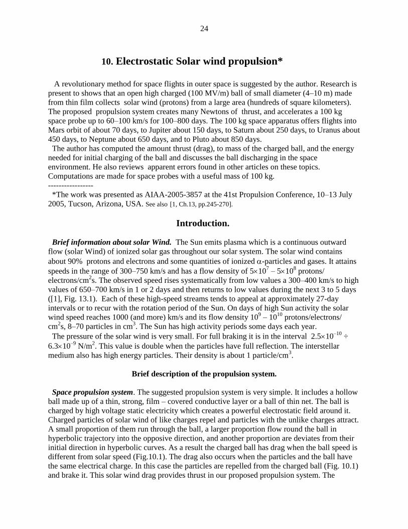
Fig. 9.1. Space launcher. Notations are: 1 – prism, 2 – mirror base, 3 – laser beam, 4 – mirror after chink
(optional), 5 – space vehicle, 6 – lasers (ring set of lasers), 7 – vehicle (ship) mirror, 8 – planet
mirror, 9 –laser beam, 10 – multi-layer dielectric mirror, 11 – laser beam after multi-reflection
(wavelength λ11 > λ9 ), 12 – additional prism, 13 – entry beam, 14 – return beam, 15 – variable chink
between main and additional prisms. (a) Prism (cell, corner cube) reflector. (b) Beam multi-reflection,
(c) Launching by multi-reflection, (d) The first design of the light lock, (e) The second design of the
light lock, (f) Reflection in the same direction when the beam is not perpendicular to mirror surface,
(g) Mirror cell (retroreflector cell or cube corner cell). A light ray incident on it is returned parallel to
itself after three reflections.
The linear light engine does not have a limit to its speed and may be used to launch space
equipment and space ships in non-rockets method described in [1] Ch.1210–29
. This method is
certain also to have many military applications.
24
10. Electrostatic Solar wind propulsion*
A revolutionary method for space flights in outer space is suggested by the author. Research is
present to shows that an open high charged (100 MV/m) ball of small diameter (4–10 m) made
from thin film collects solar wind (protons) from a large area (hundreds of square kilometers).
The proposed propulsion system creates many Newtons of thrust, and accelerates a 100 kg
space probe up to 60–100 km/s for 100–800 days. The 100 kg space apparatus offers flights into
Mars orbit of about 70 days, to Jupiter about 150 days, to Saturn about 250 days, to Uranus about
450 days, to Neptune about 650 days, and to Pluto about 850 days.
The author has computed the amount thrust (drag), to mass of the charged ball, and the energy
needed for initial charging of the ball and discusses the ball discharging in the space
environment. He also reviews apparent errors found in other articles on these topics.
Computations are made for space probes with a useful mass of 100 kg.
-----------------
*The work was presented as AIAA-2005-3857 at the 41st Propulsion Conference, 10–13 July
2005, Tucson, Arizona, USA. See also [1, Ch.13, pp.245-270].
Introduction.
Brief information about solar Wind. The Sun emits plasma which is a continuous outward
flow (solar Wind) of ionized solar gas throughout our solar system. The solar wind contains
about 90% protons and electrons and some quantities of ionized -particles and gases. It attains
speeds in the range of 300–750 km/s and has a flow density of 5107 – 510
8 protons/
electrons/cm2s. The observed speed rises systematically from low values a 300–400 km/s to high
values of 650–700 km/s in 1 or 2 days and then returns to low values during the next 3 to 5 days
([1], Fig. 13.1). Each of these high-speed streams tends to appeal at approximately 27-day
intervals or to recur with the rotation period of the Sun. On days of high Sun activity the solar
wind speed reaches 1000 (and more) km/s and its flow density 109 – 10
10 protons/electrons/
cm2s, 8–70 particles in cm
3. The Sun has high activity periods some days each year.
The pressure of the solar wind is very small. For full braking it is in the interval 2.510–10
÷
6.310–9
N/m2. This value is double when the particles have full reflection. The interstellar
medium also has high energy particles. Their density is about 1 particle/cm3.
Brief description of the propulsion system.
Space propulsion system. The suggested propulsion system is very simple. It includes a hollow
ball made up of a thin, strong, film – covered conductive layer or a ball of thin net. The ball is
charged by high voltage static electricity which creates a powerful electrostatic field around it.
Charged particles of solar wind of like charges repel and particles with the unlike charges attract.
A small proportion of them run through the ball, a larger proportion flow round the ball in
hyperbolic trajectory into the opposive direction, and another proportion are deviates from their
initial direction in hyperbolic curves. As a result the charged ball has drag when the ball speed is
different from solar speed (Fig.10.1). The drag also occurs when the particles and the ball have
the same electrical charge. In this case the particles are repelled from the charged ball (Fig. 10.1)
and brake it. This solar wind drag provides thrust in our proposed propulsion system. The
25
pressure of solar wind is very small, but the offered system (a charged ball of radius 6–10 m)
collects particles (protons or electrons) from a large area (an area of tens of kilometers radius for
protons and hundreds of kilometers for electrons), creates a thrust of some Newtons and a 100-kg
space ship reaches speeds of tens of km/s in 50–300 days (see theory and computation below and
References [1] Ch.1329, 42–47
).
The proposed new propulsion mechanism differs from previous concepts in very important
respects; including the coupling to the protons of the solar wind using an open single-charge ball.
The opposite charge is expelled into infinite space. This innovation increases the area of
influence by up to hundreds of kilometers for protons and allows the acquisition of significant
vehicle thrust. This thrust is enough to accelerate a heavy space craft to very high speed and
permits very short flight times to far planets.
The offered revolutionary propulsion system has a simple design, which can give useful
acceleration to various types of spacecraft. The offered propulsion system creates many Newtons
of thrust, and can accelerate a 100 kg space probe up to 60–100 km/sec in 100–800 days.
In the offered wind propulsion system the particles run away from the ball, brake and return in
infinity for initial speed. These premises must be examined using more complex theories to
account for the full intersection between the suggested installation and solar wind (including
thermonuclear reactions). This would be a revolutionary breakthrough in interplanetary space
exploration.
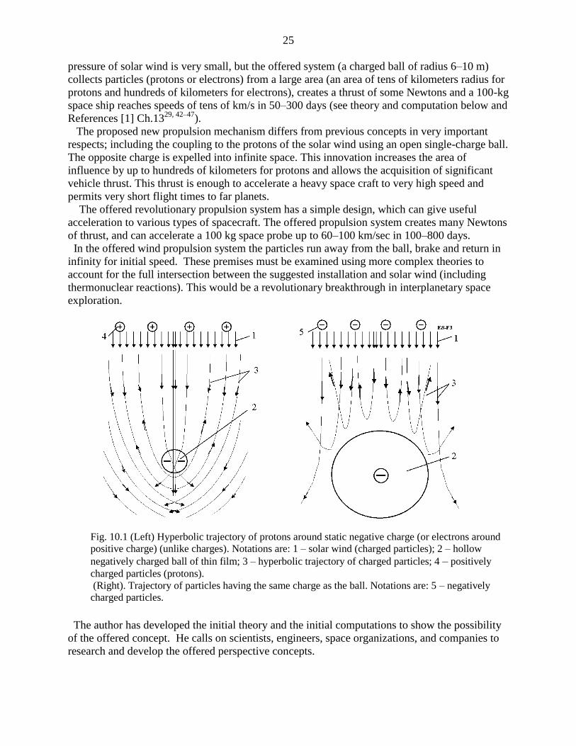
Fig. 10.1 (Left) Hyperbolic trajectory of protons around static negative charge (or electrons around
positive charge) (unlike charges). Notations are: 1 – solar wind (charged particles); 2 – hollow
negatively charged ball of thin film; 3 – hyperbolic trajectory of charged particles; 4 – positively
charged particles (protons).
(Right). Trajectory of particles having the same charge as the ball. Notations are: 5 – negatively
charged particles.
The author has developed the initial theory and the initial computations to show the possibility
of the offered concept. He calls on scientists, engineers, space organizations, and companies to
research and develop the offered perspective concepts.
26
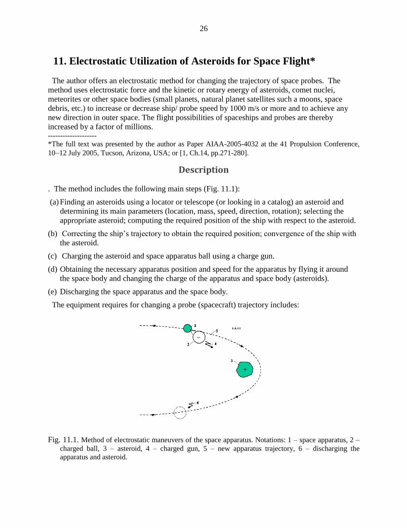
11. Electrostatic Utilization of Asteroids for Space Flight*
The author offers an electrostatic method for changing the trajectory of space probes. The
method uses electrostatic force and the kinetic or rotary energy of asteroids, comet nuclei,
meteorites or other space bodies (small planets, natural planet satellites such a moons, space
debris, etc.) to increase or decrease ship/ probe speed by 1000 m/s or more and to achieve any
new direction in outer space. The flight possibilities of spaceships and probes are thereby
increased by a factor of millions. --------------------
*The full text was presented by the author as Paper AIAA-2005-4032 at the 41 Propulsion Conference,
10–12 July 2005, Tucson, Arizona, USA; or [1, Ch.14, pp.271-280].
Description
. The method includes the following main steps (Fig. 11.1):
(a) Finding an asteroids using a locator or telescope (or looking in a catalog) an asteroid and
determining its main parameters (location, mass, speed, direction, rotation); selecting the
appropriate asteroid; computing the required position of the ship with respect to the asteroid.
(b) Correcting the ship’s trajectory to obtain the required position; convergence of the ship with
the asteroid.
(c) Charging the asteroid and space apparatus ball using a charge gun.
(d) Obtaining the necessary apparatus position and speed for the apparatus by flying it around
the space body and changing the charge of the apparatus and space body (asteroids).
(e) Discharging the space apparatus and the space body.
The equipment requires for changing a probe (spacecraft) trajectory includes:
Fig. 11.1. Method of electrostatic maneuvers of the space apparatus. Notations: 1 – space apparatus, 2 –
charged ball, 3 – asteroid, 4 – charged gun, 5 – new apparatus trajectory, 6 – discharging the
apparatus and asteroid.
27
(a) A charging gun.
(b) Devices for finding and measuring the asteroids (space bodies), and computing the trajectory
of the spacecraft relative of the space body.
(c) Devices for spacecraft guidance and control.
(d) A device for discharging of the apparatus and asteroids (space body) (see [1] Fig. 14.1).
12. Electrostatic Levitation on the Earth and Artificial Gravity for
Space Ships and Asteroids*
The author offers and researches the conditions which allow people and vehicles to levitate on
the Earth using the electrostatic repulsive force. He shows that by using small electrically
charged balls, people and cars can take flight in the atmosphere. Also, a levitated train can attain
high speeds. He has computed some projects and discusses the problems which can appear in the
practical development of this method. It is also shown how this method may be used for creating
artificial gravity (attraction force) into and out of space ships, space hotels, asteroids, and small
planets which have little gravity. -------------------
*Presented as paper AIAA-2005-4465 at 41 Propulsion Conference, 10–13 July 2005, Tucson, Arizona,
USA; or [1, Ch. 15, pp. 281-302].
Brief description of innovation
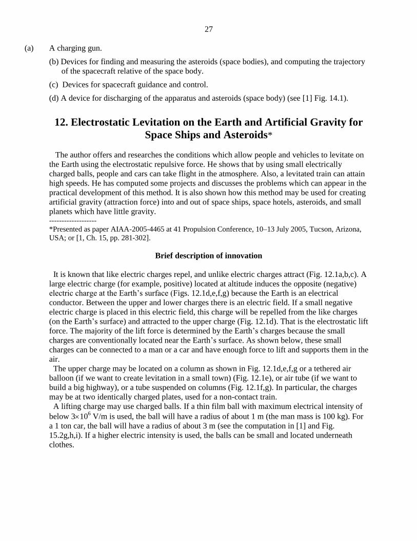
It is known that like electric charges repel, and unlike electric charges attract (Fig. 12.1a,b,c). A
large electric charge (for example, positive) located at altitude induces the opposite (negative)
electric charge at the Earth’s surface (Figs. 12.1d,e,f,g) because the Earth is an electrical
conductor. Between the upper and lower charges there is an electric field. If a small negative
electric charge is placed in this electric field, this charge will be repelled from the like charges
(on the Earth’s surface) and attracted to the upper charge (Fig. 12.1d). That is the electrostatic lift
force. The majority of the lift force is determined by the Earth’s charges because the small
charges are conventionally located near the Earth’s surface. As shown below, these small
charges can be connected to a man or a car and have enough force to lift and supports them in the
air.
The upper charge may be located on a column as shown in Fig. 12.1d,e,f,g or a tethered air
balloon (if we want to create levitation in a small town) (Fig. 12.1e), or air tube (if we want to
build a big highway), or a tube suspended on columns (Fig. 12.1f,g). In particular, the charges
may be at two identically charged plates, used for a non-contact train.
A lifting charge may use charged balls. If a thin film ball with maximum electrical intensity of
below 3106 V/m is used, the ball will have a radius of about 1 m (the man mass is 100 kg). For
a 1 ton car, the ball will have a radius of about 3 m (see the computation in [1] and Fig.
15.2g,h,i). If a higher electric intensity is used, the balls can be small and located underneath
clothes.
28
Fig. 12.1. Explanation of electrostatic levitation: a) Attraction of unlike charges; b,c) repulsion of like
charges; d) Creation of the homogeneous electric field (highway); e) Electrical field from a large
spherical charge ; f,g) Electrical field from a tube (highway) (side and front views). Notations are: 1,
9 – column, 2 – Earth (or other) surface charged by induction, 3 – net, 4 – upper charges, 5 – lower
charges, 6 – levitation apparatus, 8 – charged air balloon, 9 – column, 10 – charged tube.
13. Guided Solar Sail and Energy Generator*
A solar sail is a large thin film mirror that uses solar energy for propulsion. The author
proposed innovations and a new design of Solar sail in 1985 [1] Ch.161. This innovation allows
(main advantages only):
1) An easily controlled amount and direction of thrust without turning a gigantic sail;
2) Utilization of the solar sail as a power generator (for example, electricity generator);
3) Use of the solar sail for long-distance communication systems.
-----------------------------
* The detail manuscript was presented as AIAA-2005-3857 on the 41st Propulsion Conference,
10–12 July 2005, Tucson, Arizona, USA; or see [1, Ch.16, pp. 303-308].
Description of innovation and their advantages
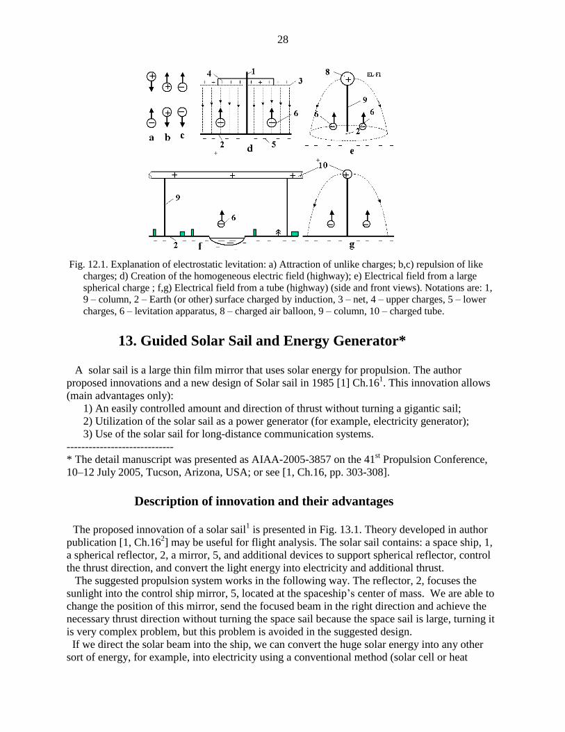
The proposed innovation of a solar sail
1 is presented in Fig. 13.1. Theory developed in author
publication [1, Ch.162] may be useful for flight analysis. The solar sail contains: a space ship, 1,
a spherical reflector, 2, a mirror, 5, and additional devices to support spherical reflector, control
the thrust direction, and convert the light energy into electricity and additional thrust.
The suggested propulsion system works in the following way. The reflector, 2, focuses the
sunlight into the control ship mirror, 5, located at the spaceship’s center of mass. We are able to
change the position of this mirror, send the focused beam in the right direction and achieve the
necessary thrust direction without turning the space sail because the space sail is large, turning it
is very complex problem, but this problem is avoided in the suggested design.
If we direct the solar beam into the ship, we can convert the huge solar energy into any other
sort of energy, for example, into electricity using a conventional method (solar cell or heat
29
machine). A reflector of 100×100 m2 produces 14,000 kW energy at 1 AU. The developed ion
thrusters are very efficient and have a high specific impulse, but they need a great amount of
energy. We have this energy in the proposed sail and can increase the thrust over time.
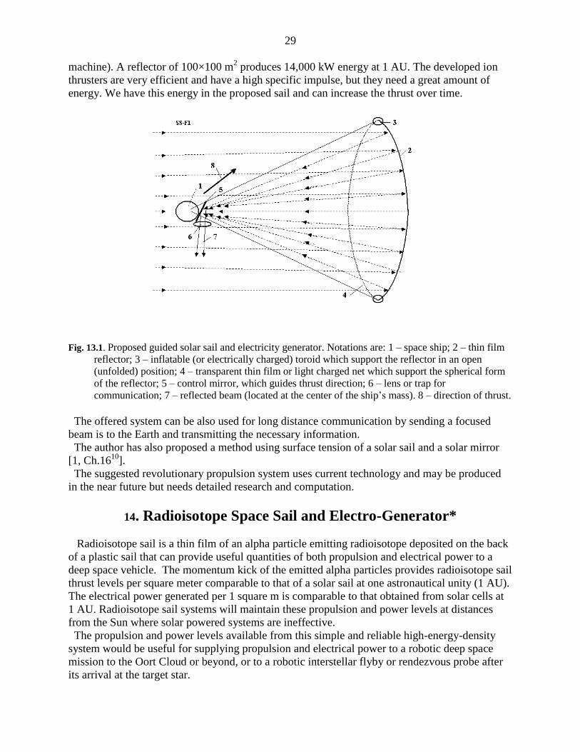
Fig. 13.1. Proposed guided solar sail and electricity generator. Notations are: 1 – space ship; 2 – thin film
reflector; 3 – inflatable (or electrically charged) toroid which support the reflector in an open
(unfolded) position; 4 – transparent thin film or light charged net which support the spherical form
of the reflector; 5 – control mirror, which guides thrust direction; 6 – lens or trap for
communication; 7 – reflected beam (located at the center of the ship’s mass). 8 – direction of thrust.
The offered system can be also used for long distance communication by sending a focused
beam is to the Earth and transmitting the necessary information.
The author has also proposed a method using surface tension of a solar sail and a solar mirror
[1, Ch.1610
].
The suggested revolutionary propulsion system uses current technology and may be produced
in the near future but needs detailed research and computation.
14. Radioisotope Space Sail and Electro-Generator*
Radioisotope sail is a thin film of an alpha particle emitting radioisotope deposited on the back
of a plastic sail that can provide useful quantities of both propulsion and electrical power to a
deep space vehicle. The momentum kick of the emitted alpha particles provides radioisotope sail
thrust levels per square meter comparable to that of a solar sail at one astronautical unity (1 AU).
The electrical power generated per 1 square m is comparable to that obtained from solar cells at
1 AU. Radioisotope sail systems will maintain these propulsion and power levels at distances
from the Sun where solar powered systems are ineffective.
The propulsion and power levels available from this simple and reliable high-energy-density
system would be useful for supplying propulsion and electrical power to a robotic deep space
mission to the Oort Cloud or beyond, or to a robotic interstellar flyby or rendezvous probe after
its arrival at the target star.

30
------------------------
* Detailed work was presented by the author as AIAA-2005-4225 at the 41st Propulsion
Conference, 10–12 July, 2005, Tucson, Arizona, USA; or see [1, Ch.17, pp.309-316].
Description of method and innovations
Brief history of innovation
The idea of using a radioisotope recoil propulsion as it is shown in Fig.14.1a is very old [1,
Ch.1715
].
The author has proposed many innovations in method is using radioisotope space sail and
electric generators in patent applications [1, Ch.171–13
] in 1983 and in paper IAF 92-0573
presented to the World Space Congress in 1992 ]1, Ch.1714
]. The work [1, Ch.1716
] written in
1995 summarized the knowledge for the conventional case in Fig. 14.1a. Bolonkin innovations
decrease the weight of traditional radioisotope sail (RadSail, RS, IsoSail) by 2–4 times; increase
the thrust by 2–3 times, and the electric power by 2 times and allows control of thrust and thrust
direction without needing to turn the large RadSail.
Fig. 14.1. a) Conventional radioisotope sail; b) suggested (innovated) radioisotope sail. Notations are: 1
– substrate (base of sail), 2 – isotope layer, 3 – isotope atom, 4 – alpha particles, 5 – direction of 1/6
particle flow, 6 – thrust, 8 – electric loading, 9 – initial charging, 10, 11, 12 – condenser nets, 13 –
particle trajectory.
Offered innovation allows us to reach a probe speed of more than 2000 km/s, so the design
may be used for interstellar probes.
This method allows nuclear waste and unnecessary nuclear bombs to be used for producing the
radioisotope material.
The offered method is realistic at the present time, has a high possibility to being successful,
and is much cheaper for deep missions than other currently proposed method.
15. Electrostatic Solar Sail* The solar sail has become well-known after much discussion in the scientific literature as a thin
continuous plastic film, covered by sunlight-reflecting appliquéd aluminum. Earlier, there were
attempts to launch and operate solar sails in near-Earth space and there are experimental projects
planned for long powered space voyages. However, as currently envisioned, the solar sail has

31
essential disadvantages. Solar light pressure in space is very low and consequently the solar sail
has to be very large in area. Also it is difficult to unfold and unfurl the solar sail in space. In
addition it is necessary to have a rigid framework to support the thin material. Such frameworks
usually have great mass and, therefore, the spacecraft’s acceleration is small.
Here, the author proposes to discard standard solar sail technology (continuous plastic
aluminum-coated film) with the intention instead of using millions of small, very thin aluminum
charged plates and to release these plates from a spacecraft, instigated by an electrostatic field.
Using this new technology, the solar sail composed of millions of plates can be made gigantic
area but have very low mass. The acceleration of this new kind of solar sail may be as much as
300 times that achieves by an ordinary solar sail. The electrostatic solar sail can even reach a
speed of about 300 km/s (in a special maneuver up to 600–800 km/sec). The electrostatic solar
sail may be used to move a large spaceship or to act as an artificial Moon illuminating a huge
region of the Earth’s surface.
----------------------
*See [1, Ch.18, pp. 317-326].
Brief description of the innovations A conventional solar sail is a dielectric thin film (thickness 5 mkm = 5000 nm) with an
aluminum layer 100 nm thick, and it has 90% reflectivity. The weight of one square meter is 5–7
g/m2. If it accelerates by itself the maximum acceleration is about 1 mm/s
2. However, the
gigantic thin film needs a rigid structure to support the very thin film in an unfolded position and
to unable it to be controlled. This rigid structure has a large weight, so it is very difficult to
launch and to unfurl the structure in space. All attempts to do this (for example, to unfurl the
inflatable radio-antennas in space) have failed. The author proposes to use small thin charged aluminums plates (petals) supported by a central
electrostatic ball and rotated around the ball (Fig. 15.1). They rotate also around their own axis
and main thin a direction perpendicular to the solar rays. The diameter of the plate-petals is
small, about 1 mm or less, and, it is not a necessity to use the dielectric film. The aluminum film
may be very thin because the individual petal size is small.
Fig. 15.1. The proposed electrostatic solar sail. a. Side view; b. Front view; c. Side and front views of
square petal; d. Side and front views of round petal. Notation: 1 – spaceship, 2 – charged ball, 3 –
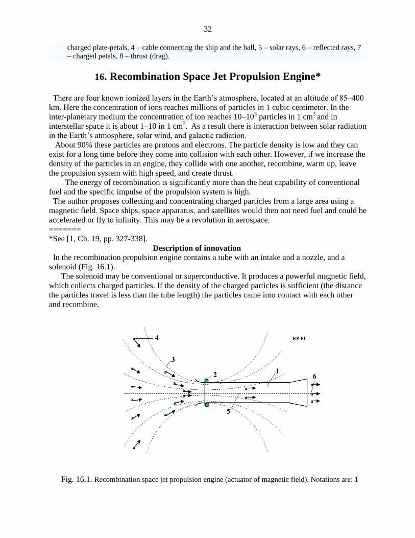
32
charged plate-petals, 4 – cable connecting the ship and the ball, 5 – solar rays, 6 – reflected rays, 7
– charged petals, 8 – thrust (drag).
16. Recombination Space Jet Propulsion Engine* There are four known ionized layers in the Earth’s atmosphere, located at an altitude of 85–400
km. Here the concentration of ions reaches millions of particles in 1 cubic centimeter. In the
inter-planetary medium the concentration of ion reaches 10–103 particles in 1 cm
3 and in
interstellar space it is about 1–10 in 1 cm3. As a result there is interaction between solar radiation
in the Earth’s atmosphere, solar wind, and galactic radiation.
About 90% these particles are protons and electrons. The particle density is low and they can
exist for a long time before they come into collision with each other. However, if we increase the
density of the particles in an engine, they collide with one another, recombine, warm up, leave
the propulsion system with high speed, and create thrust.
The energy of recombination is significantly more than the heat capability of conventional
fuel and the specific impulse of the propulsion system is high.
The author proposes collecting and concentrating charged particles from a large area using a
magnetic field. Space ships, space apparatus, and satellites would then not need fuel and could be
accelerated or fly to infinity. This may be a revolution in aerospace.
=======
*See [1, Ch. 19, pp. 327-338].
Description of innovation
In the recombination propulsion engine contains a tube with an intake and a nozzle, and a
solenoid (Fig. 16.1).
The solenoid may be conventional or superconductive. It produces a powerful magnetic field,
which collects charged particles. If the density of the charged particles is sufficient (the distance
the particles travel is less than the tube length) the particles came into contact with each other
and recombine.
Fig. 16.1. Recombination space jet propulsion engine (actuator of magnetic field). Notations are: 1
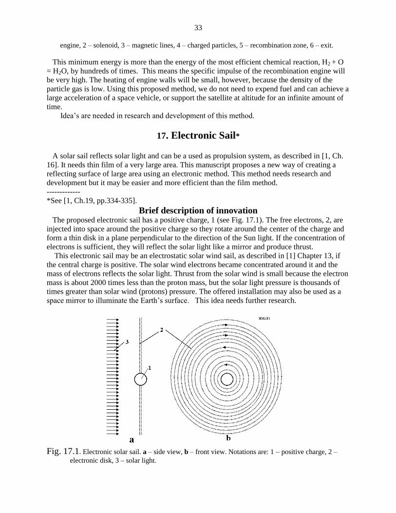
33
engine, 2 – solenoid, 3 – magnetic lines, 4 – charged particles, 5 – recombination zone, 6 – exit.
This minimum energy is more than the energy of the most efficient chemical reaction, H2 + O
= H2O, by hundreds of times. This means the specific impulse of the recombination engine will
be very high. The heating of engine walls will be small, however, because the density of the
particle gas is low. Using this proposed method, we do not need to expend fuel and can achieve a
large acceleration of a space vehicle, or support the satellite at altitude for an infinite amount of
time.
Idea’s are needed in research and development of this method.
17. Electronic Sail* A solar sail reflects solar light and can be a used as propulsion system, as described in [1, Ch.
16]. It needs thin film of a very large area. This manuscript proposes a new way of creating a
reflecting surface of large area using an electronic method. This method needs research and
development but it may be easier and more efficient than the film method.
-------------
*See [1, Ch.19, pp.334-335].
Brief description of innovation The proposed electronic sail has a positive charge, 1 (see Fig. 17.1). The free electrons, 2, are
injected into space around the positive charge so they rotate around the center of the charge and
form a thin disk in a plane perpendicular to the direction of the Sun light. If the concentration of
electrons is sufficient, they will reflect the solar light like a mirror and produce thrust.
This electronic sail may be an electrostatic solar wind sail, as described in [1] Chapter 13, if
the central charge is positive. The solar wind electrons became concentrated around it and the
mass of electrons reflects the solar light. Thrust from the solar wind is small because the electron
mass is about 2000 times less than the proton mass, but the solar light pressure is thousands of
times greater than solar wind (protons) pressure. The offered installation may also be used as a
space mirror to illuminate the Earth’s surface. This idea needs further research.
Fig. 17.1. Electronic solar sail. a – side view, b – front view. Notations are: 1 – positive charge, 2 –
electronic disk, 3 – solar light.
34
References Many works noted below the reader can find on site Cornel University <http://arxiv.org/>, sites
<http://www.scribd.com> , http://www.archive.org, <http://bolonkin.narod.ru/p65.htm> and in
Conferences 2002-2006 (see, for example, Conferences AIAA, <http://aiaa.org/> , search
"Bolonkin" )
1. Bolonkin A.A., (2005) "Non-Rocket Space Launch and Flight", Elsevier. 2005,
http://www.archive.org/details/Non-rocketSpaceLaunchAndFlight,
http://www.scribd.com/doc/24056182 2. K.E. Tsiolkovski:”Speculations Abot Earth and Sky on Vesta”, Moscow, Izd-vo AN SSSR, 1959;
Grezi o zemle i nebe (in Russian), Academy of Sciences, USSR., Moscow, p. 35, 1999.
3. Geoffrey A. Landis, Craig Cafarelli, The Tsiolkovski Tower Re-Examined, JBIS, Vol. 32, p. 176–180,
1999.
4. Y. Artsutanov. Space Elevator, http://www.liftport.com/files/Artsutanov_Pravda_SE.pdf.
5. A.C. Clarke: Fountains of Paradise, Harcourt Brace Jovanovich, New York, 1978.
6. Bolonkin A.A. (2006), Book "New Concepts, Ideas and Innovation in Aerospace", NOVA, 2008.
http://www.scribd.com/doc/24057071 . http://www.archive.org/details/NewConceptsIfeasAndInnovationsInAerospaceTechnologyAndHumanSciences
7. Bolonkin A.A. (2007), "Macro-Engineering: Environment and Technology", NOVA, 2008.
http://Bolonkin.narod.ru/p65.htm, http://www.scribd.com/doc/24057930 . http://www.archive.org/details/Macro-projectsEnvironmentsAndTechnologies
8. Bolonkin A.A. (2008), “New Technologies and Revolutionary Projects”, Scribd, 2008, 324 pgs,
http://www.scribd.com/doc/32744477 , http://www.archive.org/details/NewTechnologiesAndRevolutionaryProjects
9. Bolonkin A.A., Book "Non-Rocket Space Launch and Flight", Elsevier. 2006, Ch. 9 “Kinetic Anti-
Gravotator”, pp. 165-186; http://Bolonkin.narod.ru/p65.htm, http://www.scribd.com/doc/24056182 ;
Main idea of this Chapter was presented as papers COSPAR-02, C1.1-0035-02 and IAC-02-
IAA.1.3.03, 53rd
International Astronautical Congress. The World Space Congress-2002, 10-19 October
2002, Houston, TX, USA, and the full manuscript was accepted as AIAA-2005-4504, 41st Propulsion
Conference, 10-12 July 2005, Tucson, AZ, USA.http://aiaa.org search “Bolonkin”.
10. Bolonkin A.A., Book "Non-Rocket Space Launch and Flight", Elsevier. 2006, Ch.5 “Kinetic Space
Towers”, pp. 107-124, Springer, 2006. http://Bolonkin.narod.ru/p65.htm or
http://www.scribd.com/doc/24056182 . http://www.archive.org/details/Non-
rocketSpaceLaunchAndFlight
11. Bolonkin A.A., “Transport System for Delivery Tourists at Altitude 140 km”, manuscript was
presented as paper IAC-02-IAA.1.3.03 at the World Space Congress-2002, 10-19 October, Houston,
TX, USA. http://Bolonkin.narod.ru/p65.htm ,
12. Bolonkin A.A. (2003), “Centrifugal Keeper for Space Station and Satellites”, JBIS, Vol.56, No. 9/10,
2003, pp. 314-327. http://Bolonkin.narod.ru/p65.htm . See also [11] Ch.3.
13. Bolonkin A.A., Book "Non-Rocket Space Launch and Flight", by A.Bolonkin, Elsevier. 2006, Ch.3
”Circle Launcher and Space Keeper”, pp.59-82. http://www.scribd.com/doc/24056182 , http://www.archive.org/details/Non-rocketSpaceLaunchAndFlight
14. Bolonkin A.A., Book "New Concepts, Ideas and Innovation in Aerospace", NOVA, 2008, Ch. 3 “
Electrostatic AB-Ramjet Space Propulsion)”, pp.33-66. http://www.scribd.com/doc/24057071. http://www.archive.org/details/NewConceptsIfeasAndInnovationsInAerospaceTechnologyAndHumanSciences
15 Bolonkin A.A., Book "New Concepts, Ideas and Innovation in Aerospace", NOVA, 2008, Ch.12,
pp.205-220, “AB Levitrons and Their Applications to Earth’s Motionless Satellites”.
http://www.scribd.com/doc/24057071 , http://www.archive.org/details/NewConceptsIfeasAndInnovationsInAerospaceTechnologyAndHumanSciences

35
16. Bolonkin A.A., Book "Macro-Projects: Environment and Technology”, NOVA, 2008, Ch.10,
pp.199-226, “ AB-Space Propulsion”, http://www.scribd.com/doc/24057930 ,
http://Bolonkin.narod.ru/p65.htm . http://www.archive.org/details/Macro-projectsEnvironmentsAndTechnologies 17. Bolonkin A.A., Magnetic Suspended AB-Structures and Moveless Space Satellites.
http://www.scribd.com/doc/25883886 .
18. Bolonkin A.A., Femtotechnology: Design of the Strongest AB-Matter for Aerospace. http://www.archive.org/details/FemtotechnologyDesignOfTheStrongestAb-matterForAerospace.
19. Bolonkin A.A., Converting of any Matter to Nuclear Energy by AB-Generator and Aerospace . http://www.archive.org/details/ConvertingOfAnyMatterToNuclearEnergyByAb-generatorAndAerospace.
20. Bolonkin A.A., LIFE. SCIENCE. FUTURE (Biography notes, researches and innovations). Scribd, 2010,
208 pgs. 16 Mb. http://www.scribd.com/doc/48229884, http://www.archive.org/details/Life.Science.Future.biographyNotesResearchesAndInnovations 21. Krinker M., Magnetic-Space-Launcher. http://www.scribd.com/doc/24051286/
22. Krinker M., Review of Space Towers. http://www.scribd.com/doc/26270139,
http://arxiv.org/ftp/arxiv/papers/1002/1002.2405.pdf 23. Pensky O.G., Monograph “Mathematical Models of Emotional Robots”, Perm, 2010, 193 ps
(in English and Russian) (http://arxiv.org/ftp/arxiv/papers/1011/1011.1841.pdf ).
24. Pensky O.G., K. V. Chernikov“Fundamentals of Mathematical Theory of Emotional Robots “
(http://www.scribd.com/doc/40640088/).
25. Wikipedia. Some background material in this article is gathered from Wikipedia under
the Creative Commons license. http://wikipedia.org .
2010