Embed Size (px)
Citation preview
Review
Direct Ink Writing Technology (3D Printing) of
Graphene-Based Ceramic Nanocomposites: A Review
Nestor Washington Solís Pinargote*, Anton Smirnov*, Nikita Peretyagin, Anton Seleznev and
Pavel Peretyagin
Moscow State University of Technology “STANKIN”, Vadkovsky per. 1, Moscow, 127055, Russian
Federation; [email protected] (N.P.); [email protected] (A.S.); [email protected] (P.P.)
* Correspondence: [email protected] (N.W.S.P.); [email protected] (A.S.); Tel.: +7-4999-7323-70
(N.W.S.P.) and (A.S.)
Abstract: In the present work, the state of the art of the most common additive manufacturing (AM)
technologies used for the manufacturing of complex shape structures of graphene-based ceramic
nanocomposites, ceramic and graphene-based parts is explained. A brief overview of the AM
processes for ceramic, which are grouped by the type of feedstock used in each technology, is
presented. The main technical factors that affect the quality of the final product were reviewed. The
AM processes used for 3D printing of graphene-based materials are described in more detail;
moreover, some studies in a wide range of applications related to these AM techniques are cited.
Furthermore, different feedstock formulations and their corresponding rheological behaviour were
explained. Additionally, the most important works about the fabrication of composites using
graphene-based ceramic pastes by Direct Ink Writing (DIW) are disclosed in detail and illustrated
with representative examples. Various examples of the most relevant approaches for the
manufacturing of graphene-based ceramic nanocomposites by DIW are provided.
Keywords: additive manufacturing; graphene oxide; graphene-based paste; direct ink writing;
ceramic nanocomposites
1. Introduction
A ceramic is a nonmetallic, inorganic solid [1], which has exceptional and diverse physical and
chemical properties that characterize it as a multipurpose material. Typical properties that can be
found in ceramics materials are ultra-high-temperature ability, excellent wear resistance, great
hardness and mechanical strength, high melting points, good thermal stability, and chemical
inertness, low density, and low electrical and thermal conductivity. Thanks to these properties,
ceramics are used in multifunctional applications such as biomedical engineering, electronics,
aerospace, chemical industry, and machinery [2]. Note that the advantage of ceramics over other
materials is the ability to obtain predetermined characteristics by changing the raw materials
composition and the production technology [3-8]. Commonly, raw materials are composed by
mixtures of ceramic powders with or without binders and additives, and these mixtures are used to
form green bodies with desired simple shape by different forming methods as dry pressing, slip
casting, injection molding, gel casting, tape casting, extrusion and others [9,10]. After forming, the
green parts are very soft; therefore, it is necessary to apply heat upon them to get a dense product by
sintering. Sintering can be defined as a thermal process at higher temperatures with or without
pressure for compacting and forming a solid structure via mass transport events that often occur on
the diffusional processes [10,11]. Although traditional methods of ceramic forming are well studied
and widespread, they have several drawbacks such as high cost, long processing times and the
impossibility of producing pieces with interconnected holes or with highly complex shapes. In
addition, for obtaining a sintered ceramic part with high surface quality and accuracy, mechanical
Preprints (www.preprints.org) | NOT PEER-REVIEWED | Posted: 23 April 2020 doi:10.20944/preprints202004.0409.v1
© 2020 by the author(s). Distributed under a Creative Commons CC BY license.
2 of 55
post-processing work is necessary. This post-process work is expensive and time-consuming due to
their natural high hardness and brittleness of ceramics materials [2,12].
Over the past 30 years, a new technology for processing materials called additive manufacturing
(AM) has been developed rapidly and it is being introduced more and more every day in a wide
range of fields. AM, also known as three-dimensional (3D) printing technologies [13], can be
described as a technique of blending materials by either fusion, binding, or solidifying materials such
as liquid resin and powders of different materials. It builds a part in a layer-by-layer fashion using
3D computer-aided design (CAD) modeling [14].
AM involves a group of advanced manufacturing technologies that allow the flexible production
of highly complex and precise structures that are difficult to realize using traditional fabrication
methods like casting and machining [15].
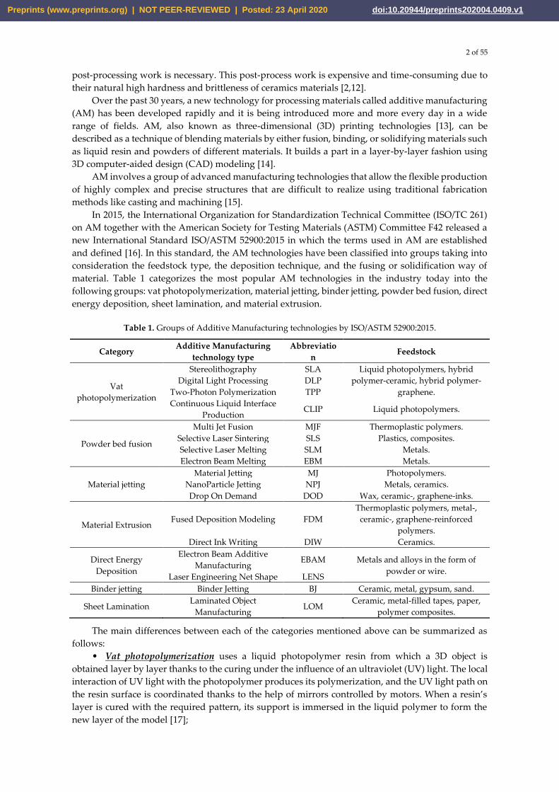
In 2015, the International Organization for Standardization Technical Committee (ISO/TC 261)
on AM together with the American Society for Testing Materials (ASTM) Committee F42 released a
new International Standard ISO/ASTM 52900:2015 in which the terms used in AM are established
and defined [16]. In this standard, the AM technologies have been classified into groups taking into
consideration the feedstock type, the deposition technique, and the fusing or solidification way of
material. Table 1 categorizes the most popular AM technologies in the industry today into the
following groups: vat photopolymerization, material jetting, binder jetting, powder bed fusion, direct
energy deposition, sheet lamination, and material extrusion.
Table 1. Groups of Additive Manufacturing technologies by ISO/ASTM 52900:2015.
Category Additive Manufacturing
technology type
Abbreviatio
n Feedstock
Vat
photopolymerization
Stereolithography SLA Liquid photopolymers, hybrid
polymer-ceramic, hybrid polymer-
graphene.
Digital Light Processing DLP
Two-Photon Polymerization TPP
Continuous Liquid Interface
Production CLIP Liquid photopolymers.
Powder bed fusion
Multi Jet Fusion MJF Thermoplastic polymers.
Selective Laser Sintering SLS Plastics, composites.
Selective Laser Melting SLM Metals.
Electron Beam Melting EBM Metals.
Material jetting
Material Jetting MJ Photopolymers.
NanoParticle Jetting NPJ Metals, ceramics.
Drop On Demand DOD Wax, ceramic-, graphene-inks.
Material Extrusion Fused Deposition Modeling FDM
Thermoplastic polymers, metal-,
ceramic-, graphene-reinforced
polymers.
Direct Ink Writing DIW Ceramics.
Direct Energy
Deposition
Electron Beam Additive
Manufacturing EBAM Metals and alloys in the form of
powder or wire. Laser Engineering Net Shape LENS
Binder jetting Binder Jetting BJ Ceramic, metal, gypsum, sand.
Sheet Lamination Laminated Object
Manufacturing LOM
Ceramic, metal-filled tapes, paper,
polymer composites.
The main differences between each of the categories mentioned above can be summarized as
follows:
• Vat photopolymerization uses a liquid photopolymer resin from which a 3D object is
obtained layer by layer thanks to the curing under the influence of an ultraviolet (UV) light. The local
interaction of UV light with the photopolymer produces its polymerization, and the UV light path on
the resin surface is coordinated thanks to the help of mirrors controlled by motors. When a resin’s
layer is cured with the required pattern, its support is immersed in the liquid polymer to form the
new layer of the model [17];
Preprints (www.preprints.org) | NOT PEER-REVIEWED | Posted: 23 April 2020 doi:10.20944/preprints202004.0409.v1
3 of 55
• Material jetting is a group of technologies that are common compared to the two-
dimensional (2D) inkjet printing. Material, which mainly contains a photopolymer, is dropped onto
a platform, where it hardens thanks to the expose of a UV light; thereby, a part is assembled layer by
layer. Material is dropped from a nozzle which moves on the platform surface [17];
• In binder jetting the 3D object is formed layer by layer, when a liquid binder is supplied by
drops onto a powder bed. In this way, the binder acts as glue for the powder layers when it is
dispersed by a print head that moves on the powder bed surface forming the necessary pattern. When
a layer is formed, the powder bed is moving down by an elevator system. After that, a tinny powder
layer is spreading over the past layer and the print head dispenses the binder again to form the next
layer [17];
• The powder bed fusion technologies utilize an energy source that allows the local sintering
or melting between the particles of a material powder. The solid part forming is producing thanks to
a layer by layer process. In these technologies, the type of use energy sources can be, for example,
lasers or electron beams. Its choice depends on the material powder, for metals is necessary the
electron beam and vacuum, while polymers require the use of lasers. Despite this, all the powder bed
fusion technologies use a spreading system of the powder material over past layers [17];
• Direct energy deposition involves technologies that form parts directly by the melting of
powder material as it is deposited. Despite that, the main idea of this technology must be applied for
a wide kind of materials (polymers, ceramics, and metal framework composites) it is predominantly
used with wire or metal powders. This fact explains why this technology is often called metal
deposition. This technology uses a nozzle that can move freely in any direction of the x, y and z axis
to deposit the raw material onto the predetermined surface and where it is automatically melted and
solidified [17];
• In sheet lamination, the part is formed from sheets of material that are then bonded. First, a
single layer of solid material is put onto the work surface and bonds it to the previous layers. Then a
necessary 2D pattern is cutting into the last bonded layer. After that, a new sheet of material is put
onto the preceding layer and all the process is repeated;
• Material extrusion includes different technologies that extrude material through a nozzle
onto a platform. Depending on the used material this technology can use a thermal source for
polymers melting to get the optimal rheological properties for extruding. In other cases, a paste with
a controlled composition of solid and liquid phases is used. The nozzle moves over the platform
drawing the necessary pattern for creating a 3D part layer by layer. In the last past years, this
technology became popular in the world for its use in the 3D printers [17].
The introduction of AM into the ceramic forming process proposes a powerful way of producing
complex 3D parts. However, despite the wide variety of AM technologies, only a few of them can be
implemented for printing ceramic parts [13]. Among such technologies, the so-called Direct Ink
Writing (DIW) offers greater versatility and particular suitability for the fabrication of ceramic parts
[18]. DIW, also referred to as Robocasting [19], is an extrusion-based technique [20,21] used in 3D
printing in which new materials can be implemented most economically and flexibly [22]. The main
requirement of this technology is the use of pastes with controlled rheological behaviour [23] that
allows them to be able to be extruded into filaments capable of maintaining their shape [23] and not
collapsing during the 3D object forming process [24]. The required rheological characteristics can be
achieved through the correct selection of the number of components, solid phase parameters and the
additives used [24].
In the industrial manufacture of ceramic parts, it is very common the use of a slurry that contains
various additives, such as plasticizers, dispersants, surfactants, binders, defoamers, lubricants, etc.,
which in many occasions produce the formation of defects during sintering [25-27]. These defects can
be related to the evaporation of the aforementioned additives that leads to volumetric shrinkage and
crack formation, which considerably reduce the mechanical properties of the part [1,28].
Some years ago, the use of chemically modified graphene (in other words, graphene oxide (GO))
has been proposed with aim of prepare an aqueous paste without any additive for the 3D printing of
graphene-based heaters [29]. Later, García-Tunon et al. [30] formulated free additives pastes of
Preprints (www.preprints.org) | NOT PEER-REVIEWED | Posted: 23 April 2020 doi:10.20944/preprints202004.0409.v1
4 of 55
diverse materials, based only on the use of GO as a dispersant, rheological modifier, and binder. It
was possible, because GO has a great similarity to clay, including its viscoelastic behaviour. Clay has
a unique structure and chemistry that allows the formulation of water-based suspensions with ideal
viscoelastic behaviour for shaping in a way that cannot be done with any other natural material
[31,32]. The special combination of surface chemistry and the structure of GO sheets in contact with
water under special conditions allow the preparation of a very stable GO suspension with viscoelastic
behaviour comparable to clay [30,33,34]. In addition, GO as an oxide can be homogeneously
dispersed in water, and, consequently, mixtures of graphene oxide with any ceramic oxide can be
processed following conventional ceramic processing routes [35-39]. Therefore, the implementation
of GO to obtain ceramic pastes without additives for their use in AM opens up new possibilities for
obtaining complex parts with the help of robocasting technology.
The aim of the present work is to explain the state of the art of the most common AM
technologies used for the manufacturing of complex shape structures of both ceramic and graphene-
based parts; and, disclose the most important works about the fabrication of composites using
graphene-based ceramic pastes by DIW. Where it was necessary, an explanation of important aspects
of AM techniques for ceramic or graphene-based materials will be presented. Moreover, overviews
of diverse examples of graphene-based pastes for DIW are given. In where it was possible, historical
facts of diverse AM techniques were explained.
Our review article is organized as follows: in Section 2 we present a brief overview of the AM
processes for ceramic, which are grouped by the type of feedstock used in each technology; besides,
we tried to summarize their principles and applications, and to provide their most important
historical facts. Section 3 describes in more detail the AM processes used for 3D printing of graphene-
based materials and cites some studies in a wide range of applications related to these AM techniques.
Different feedstock formulations and their corresponding rheological behaviour were explained.
Section 4 is focused on the more actual developments on direct ink writing by the use of graphene-
based ceramic pastes. We provide some examples of the most relevant approaches for the
manufacturing of graphene-based ceramic composites by DIW. Finally, in Section 5 a summary of
this work is described.
2. Additive Manufacturing processes for ceramic and their principles
The beginning of AM technologies dates back to July 16, 1984, when André J.C., Le Mehauté A.
and De Witte O. filed a patent at Cilas Alcatel [40], in which the stereolithography process was
proposed. Three weeks later, on August 8, 1984, Charles W. Hull filed his patent at UVP, Inc. [41] and
coined the term “stereolithography” (SLA). After that, the development of AM was followed by
technologies as powder bed fusion, fused deposition modelling (FDM), inkjet printing and others
[42]. However, it was only in the 1990s when the first reports of 3D printing of ceramic materials
appeared [43, 44].
Today there is a wide variety of AM technologies used for different types of materials. Table 1
lists the most popular manufacturing additive technologies in the industry, and the possible types of
feedstock that can be used in each technology. From this, it is easy to appreciate that not all AM
technologies are suitable for the processing of ceramic materials [13].
In 1991, Professor J.P. Kruth first organized the AM processes according to the form of the used
material before printing [45], and his classifications were: powder, solid and liquid-based techniques.
Using this principle, it is possible to group the AM technologies for ceramic materials into powder-
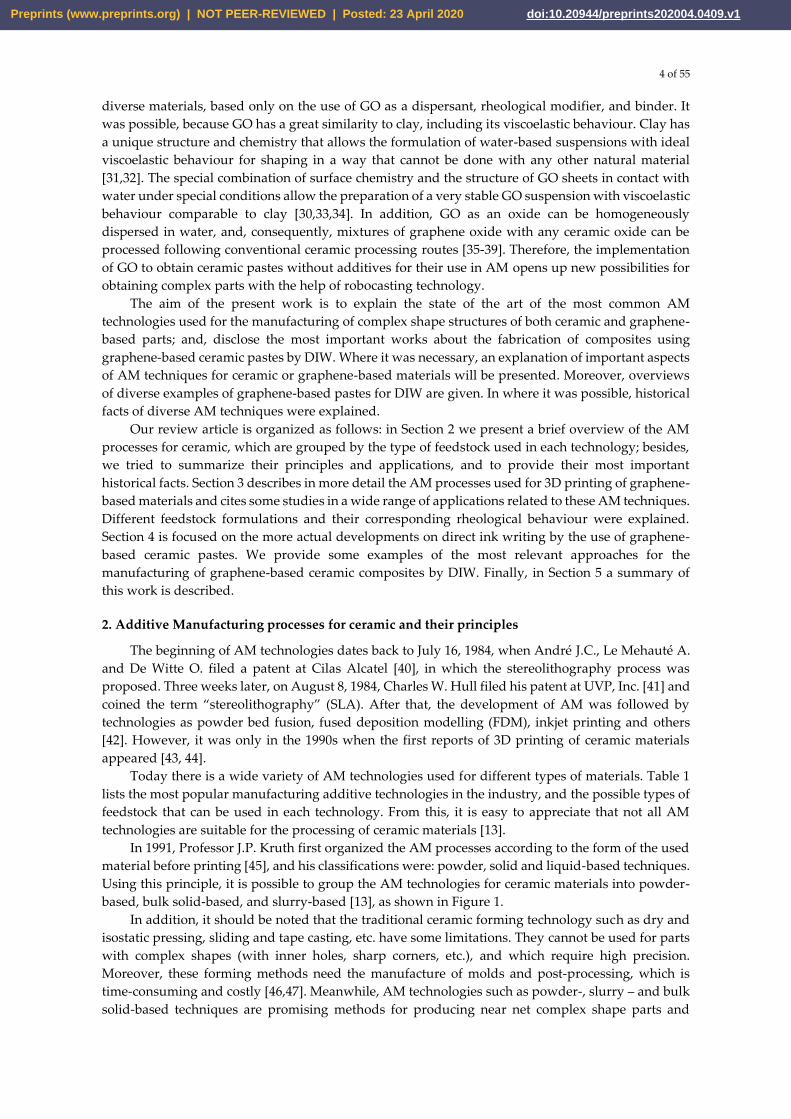
based, bulk solid-based, and slurry-based [13], as shown in Figure 1.
In addition, it should be noted that the traditional ceramic forming technology such as dry and
isostatic pressing, sliding and tape casting, etc. have some limitations. They cannot be used for parts
with complex shapes (with inner holes, sharp corners, etc.), and which require high precision.
Moreover, these forming methods need the manufacture of molds and post-processing, which is
time-consuming and costly [46,47]. Meanwhile, AM technologies such as powder-, slurry – and bulk
solid-based techniques are promising methods for producing near net complex shape parts and
Preprints (www.preprints.org) | NOT PEER-REVIEWED | Posted: 23 April 2020 doi:10.20944/preprints202004.0409.v1
5 of 55
consequently allows for saving time and reducing production costs of required products in
comparison with traditional forming methods.
Figure 1. Classification of AM technologies for ceramics by the type of feedstock used: SLS –
Selective Laser Sintering; BJ - Binder Jetting; SLM - Selective Laser Melting; SLA –
Stereolithography; DLP - Digital Light Processing; TPP - Two-Photon Polymerization; IJP – Ink Jet
printing; LOM - Laminated Object Manufacturing; FDM - Fused Deposition Modeling and DIW -
Direct Ink Writing.
2.1. Powder-based technologies
In this group of AM technologies for ceramic materials, powder beds are used. During the
additive process, the ceramic powder can be bonded by melting, sintering, or a binder agent,
depending on the type of technology used. Among the AM technologies that utilize powder beds, for
ceramic materials three of them are the most important in the industry: selective laser sintering (SLS),
selective laser melting (SLM) and binder jetting (BJ).
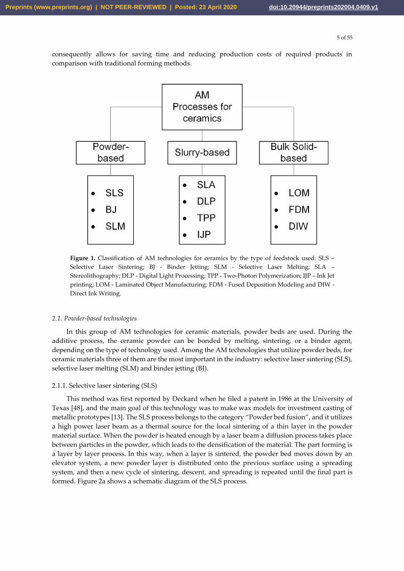
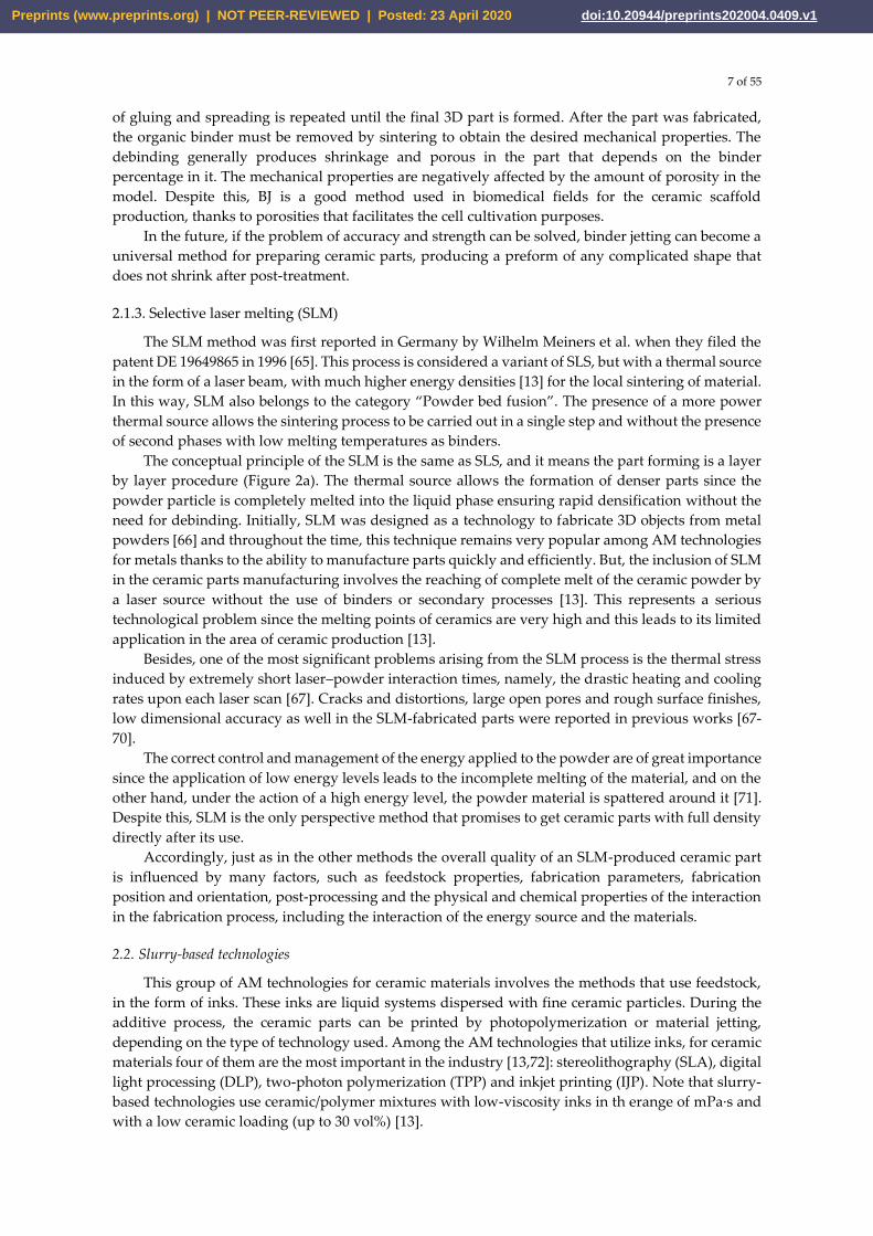
2.1.1. Selective laser sintering (SLS)
This method was first reported by Deckard when he filed a patent in 1986 at the University of
Texas [48], and the main goal of this technology was to make wax models for investment casting of
metallic prototypes [13]. The SLS process belongs to the category “Powder bed fusion”, and it utilizes
a high power laser beam as a thermal source for the local sintering of a thin layer in the powder
material surface. When the powder is heated enough by a laser beam a diffusion process takes place
between particles in the powder, which leads to the densification of the material. The part forming is
a layer by layer process. In this way, when a layer is sintered, the powder bed moves down by an
elevator system, a new powder layer is distributed onto the previous surface using a spreading
system, and then a new cycle of sintering, descent, and spreading is repeated until the final part is
formed. Figure 2a shows a schematic diagram of the SLS process.
Preprints (www.preprints.org) | NOT PEER-REVIEWED | Posted: 23 April 2020 doi:10.20944/preprints202004.0409.v1
6 of 55
Figure 2. Schematic diagrams of powder-based AM technologies main methods: (a) Selective laser
sintering (SLS) and Selective laser melting (SLM); (b) Binder jetting (BJ). Adapted with permission
from Ref. [301]. Copyright 2018, Wiley‐VCH Verlag GmbH & Co. KGaA, Weinheim.
The powder bed can be a single material with a low melting point, or a mixture of a high melting
point material together with inorganic [49-54] or organic [55-57] binders which may need debinding
by high-temperature heat treatment [58] to get the final part. The SLS process must be carried out in
vacuum or inert atmospheres such as argon and nitrogen to avoid the oxidation of the binder during
sintering. An advantage of this method is that it does not need the creation of additional supports
since the low sintering temperatures do not produce internal stresses that can deform the fabricated
part.
Although the laser beam can generate a high local temperature, it is not enough for the sintering
of the ceramic materials. Thus, it also requires a long dwell time of the laser beam exposition for
ceramics. A solution can be to coat or mix the ceramics with materials of lower melting points that
will act as binders [13]. This approach was used by Lakshminarayan et al. in 1990, when they reported
the first complex shape 3D part obtained by SLS [49, 59].
Moreover, two major problems related to SLS of ceramics are the high shrinkage and the high
porosity remaining in the final parts [60]. On the other hand, the benefit of this method is that no
extra support structures have to be intentionally prepared for overhanging regions during an SLS
process, as they are surrounded by the loose powder in the bed at all times. Thus, the properties of
the parts produced by SLS are affected by several factors associated mainly with the feedstock
materials and laser–material interactions should be taken into account during the fabrication process.
2.1.2. Binder jetting (BJ)
Binder jetting is a process invented 1989 by Sachs et al. when they filed a patent for it at
Massachusetts Institute of Technology [61], and thanks to its main characteristics, it belongs to the
category “Binder jetting”. The principal objective of this technology was to rapidly-produce of parts
from a larger variety of materials [13] as plastics [62], metals [63] and ceramics [64]. The BJ process
utilizes an organic binder solution that is dropped into a powder bed for the gluing of particles in the
surface by a printhead in determinated paths. The scheme of the BJ process is shown in Figure 2b.
The first report about the application of the BJ process on ceramic materials was made by Sachs
et al., in 1992, when they used a matrix of alumina and silicon carbide with a colloidal silica as a
binder [64]. Any ceramic powders, which are easier to prepare than wires, sheets, or ceramic slurries,
can be used to prepare ceramic preforms, and color printing all of these provide the benefit of BJ with
regards to other fabrication methods. However, it must be mentioned that the accuracy and strength
of ceramic parts are closely related to powder, binder, printing parameters, equipment, and post-
treatment.
In BJ, like SLS, the part forming is a layer by layer process. When a layer is solidified, a new
powder layer is distributed onto the previous surface using a spreading system, and then a new cycle
Preprints (www.preprints.org) | NOT PEER-REVIEWED | Posted: 23 April 2020 doi:10.20944/preprints202004.0409.v1
7 of 55
of gluing and spreading is repeated until the final 3D part is formed. After the part was fabricated,
the organic binder must be removed by sintering to obtain the desired mechanical properties. The
debinding generally produces shrinkage and porous in the part that depends on the binder
percentage in it. The mechanical properties are negatively affected by the amount of porosity in the
model. Despite this, BJ is a good method used in biomedical fields for the ceramic scaffold
production, thanks to porosities that facilitates the cell cultivation purposes.
In the future, if the problem of accuracy and strength can be solved, binder jetting can become a
universal method for preparing ceramic parts, producing a preform of any complicated shape that
does not shrink after post-treatment.
2.1.3. Selective laser melting (SLM)
The SLM method was first reported in Germany by Wilhelm Meiners et al. when they filed the
patent DE 19649865 in 1996 [65]. This process is considered a variant of SLS, but with a thermal source
in the form of a laser beam, with much higher energy densities [13] for the local sintering of material.
In this way, SLM also belongs to the category “Powder bed fusion”. The presence of a more power
thermal source allows the sintering process to be carried out in a single step and without the presence
of second phases with low melting temperatures as binders.
The conceptual principle of the SLM is the same as SLS, and it means the part forming is a layer
by layer procedure (Figure 2a). The thermal source allows the formation of denser parts since the
powder particle is completely melted into the liquid phase ensuring rapid densification without the
need for debinding. Initially, SLM was designed as a technology to fabricate 3D objects from metal
powders [66] and throughout the time, this technique remains very popular among AM technologies
for metals thanks to the ability to manufacture parts quickly and efficiently. But, the inclusion of SLM
in the ceramic parts manufacturing involves the reaching of complete melt of the ceramic powder by
a laser source without the use of binders or secondary processes [13]. This represents a serious
technological problem since the melting points of ceramics are very high and this leads to its limited
application in the area of ceramic production [13].
Besides, one of the most significant problems arising from the SLM process is the thermal stress
induced by extremely short laser–powder interaction times, namely, the drastic heating and cooling
rates upon each laser scan [67]. Cracks and distortions, large open pores and rough surface finishes,
low dimensional accuracy as well in the SLM-fabricated parts were reported in previous works [67-
70].
The correct control and management of the energy applied to the powder are of great importance
since the application of low energy levels leads to the incomplete melting of the material, and on the
other hand, under the action of a high energy level, the powder material is spattered around it [71].
Despite this, SLM is the only perspective method that promises to get ceramic parts with full density
directly after its use.
Accordingly, just as in the other methods the overall quality of an SLM-produced ceramic part
is influenced by many factors, such as feedstock properties, fabrication parameters, fabrication
position and orientation, post-processing and the physical and chemical properties of the interaction
in the fabrication process, including the interaction of the energy source and the materials.
2.2. Slurry-based technologies
This group of AM technologies for ceramic materials involves the methods that use feedstock,
in the form of inks. These inks are liquid systems dispersed with fine ceramic particles. During the
additive process, the ceramic parts can be printed by photopolymerization or material jetting,
depending on the type of technology used. Among the AM technologies that utilize inks, for ceramic
materials four of them are the most important in the industry [13,72]: stereolithography (SLA), digital
light processing (DLP), two-photon polymerization (TPP) and inkjet printing (IJP). Note that slurry-
based technologies use ceramic/polymer mixtures with low-viscosity inks in th erange of mPa·s and
with a low ceramic loading (up to 30 vol%) [13].
Preprints (www.preprints.org) | NOT PEER-REVIEWED | Posted: 23 April 2020 doi:10.20944/preprints202004.0409.v1
8 of 55
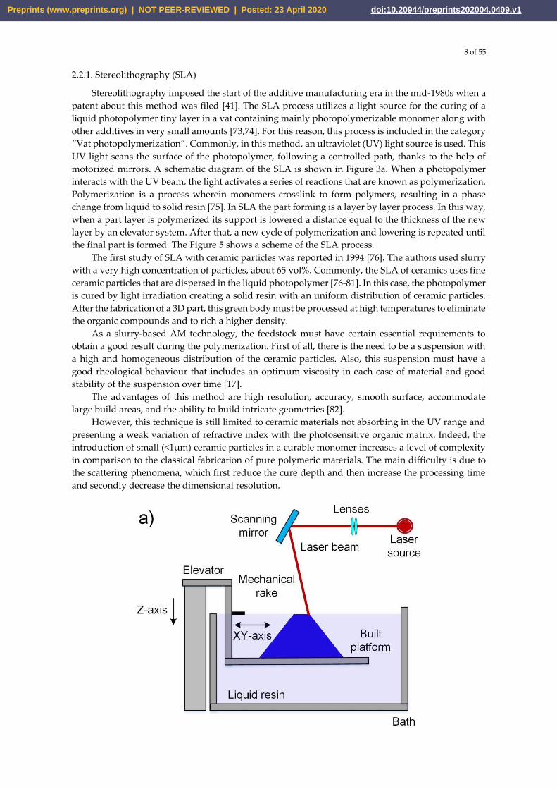
2.2.1. Stereolithography (SLA)
Stereolithography imposed the start of the additive manufacturing era in the mid-1980s when a patent about this method was filed [41]. The SLA process utilizes a light source for the curing of a liquid photopolymer tiny layer in a vat containing mainly photopolymerizable monomer along with other additives in very small amounts [73,74]. For this reason, this process is included in the category “Vat photopolymerization”. Commonly, in this method, an ultraviolet (UV) light source is used. This UV light scans the surface of the photopolymer, following a controlled path, thanks to the help of motorized mirrors. A schematic diagram of the SLA is shown in Figure 3a. When a photopolymer interacts with the UV beam, the light activates a series of reactions that are known as polymerization. Polymerization is a process wherein monomers crosslink to form polymers, resulting in a phase change from liquid to solid resin [75]. In SLA the part forming is a layer by layer process. In this way, when a part layer is polymerized its support is lowered a distance equal to the thickness of the new layer by an elevator system. After that, a new cycle of polymerization and lowering is repeated until the final part is formed. The Figure 5 shows a scheme of the SLA process.
The first study of SLA with ceramic particles was reported in 1994 [76]. The authors used slurry with a very high concentration of particles, about 65 vol%. Commonly, the SLA of ceramics uses fine ceramic particles that are dispersed in the liquid photopolymer [76-81]. In this case, the photopolymer is cured by light irradiation creating a solid resin with an uniform distribution of ceramic particles. After the fabrication of a 3D part, this green body must be processed at high temperatures to eliminate the organic compounds and to rich a higher density.
As a slurry-based AM technology, the feedstock must have certain essential requirements to obtain a good result during the polymerization. First of all, there is the need to be a suspension with a high and homogeneous distribution of the ceramic particles. Also, this suspension must have a good rheological behaviour that includes an optimum viscosity in each case of material and good stability of the suspension over time [17].
The advantages of this method are high resolution, accuracy, smooth surface, accommodate large build areas, and the ability to build intricate geometries [82].
However, this technique is still limited to ceramic materials not absorbing in the UV range and presenting a weak variation of refractive index with the photosensitive organic matrix. Indeed, the introduction of small (<1µm) ceramic particles in a curable monomer increases a level of complexity in comparison to the classical fabrication of pure polymeric materials. The main difficulty is due to the scattering phenomena, which first reduce the cure depth and then increase the processing time and secondly decrease the dimensional resolution.
Preprints (www.preprints.org) | NOT PEER-REVIEWED | Posted: 23 April 2020 doi:10.20944/preprints202004.0409.v1
9 of 55
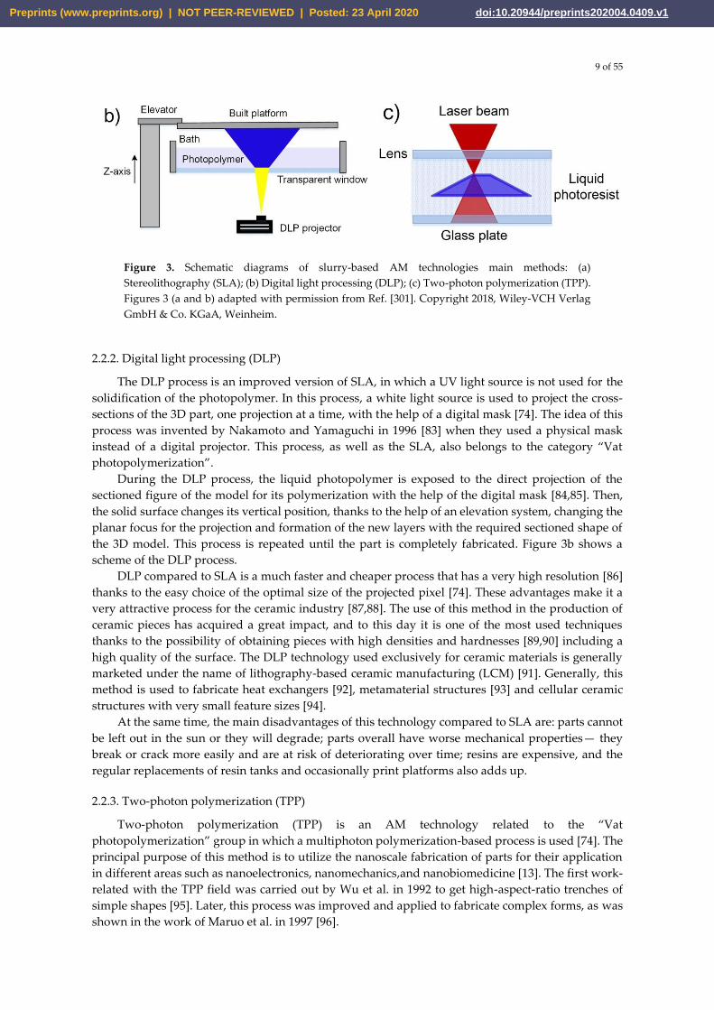
Figure 3. Schematic diagrams of slurry-based AM technologies main methods: (a)
Stereolithography (SLA); (b) Digital light processing (DLP); (c) Two-photon polymerization (TPP).
Figures 3 (a and b) adapted with permission from Ref. [301]. Copyright 2018, Wiley‐VCH Verlag
GmbH & Co. KGaA, Weinheim.
2.2.2. Digital light processing (DLP)
The DLP process is an improved version of SLA, in which a UV light source is not used for the
solidification of the photopolymer. In this process, a white light source is used to project the cross-
sections of the 3D part, one projection at a time, with the help of a digital mask [74]. The idea of this
process was invented by Nakamoto and Yamaguchi in 1996 [83] when they used a physical mask
instead of a digital projector. This process, as well as the SLA, also belongs to the category “Vat
photopolymerization”.
During the DLP process, the liquid photopolymer is exposed to the direct projection of the
sectioned figure of the model for its polymerization with the help of the digital mask [84,85]. Then,
the solid surface changes its vertical position, thanks to the help of an elevation system, changing the
planar focus for the projection and formation of the new layers with the required sectioned shape of
the 3D model. This process is repeated until the part is completely fabricated. Figure 3b shows a
scheme of the DLP process.
DLP compared to SLA is a much faster and cheaper process that has a very high resolution [86]
thanks to the easy choice of the optimal size of the projected pixel [74]. These advantages make it a
very attractive process for the ceramic industry [87,88]. The use of this method in the production of
ceramic pieces has acquired a great impact, and to this day it is one of the most used techniques
thanks to the possibility of obtaining pieces with high densities and hardnesses [89,90] including a
high quality of the surface. The DLP technology used exclusively for ceramic materials is generally
marketed under the name of lithography-based ceramic manufacturing (LCM) [91]. Generally, this
method is used to fabricate heat exchangers [92], metamaterial structures [93] and cellular ceramic
structures with very small feature sizes [94].
At the same time, the main disadvantages of this technology compared to SLA are: parts cannot
be left out in the sun or they will degrade; parts overall have worse mechanical properties— they
break or crack more easily and are at risk of deteriorating over time; resins are expensive, and the
regular replacements of resin tanks and occasionally print platforms also adds up.
2.2.3. Two-photon polymerization (TPP)
Two-photon polymerization (TPP) is an AM technology related to the “Vat
photopolymerization” group in which a multiphoton polymerization-based process is used [74]. The
principal purpose of this method is to utilize the nanoscale fabrication of parts for their application
in different areas such as nanoelectronics, nanomechanics,and nanobiomedicine [13]. The first work-
related with the TPP field was carried out by Wu et al. in 1992 to get high-aspect-ratio trenches of
simple shapes [95]. Later, this process was improved and applied to fabricate complex forms, as was
shown in the work of Maruo et al. in 1997 [96].
Preprints (www.preprints.org) | NOT PEER-REVIEWED | Posted: 23 April 2020 doi:10.20944/preprints202004.0409.v1
10 of 55
The polymerization process in TPP is based on the interaction of two or more photons from a
laser with a specific wavelength [13] when it focuses on a specific point within a liquid photopolymer
[96-97]. A schematic diagram of the TPP is shown in Figure 3c. After polymerization of a certain
volume of material, the focus point of the laser is moved for the formation of the following layers.
The final resolution and the quality of the surface obtained depend directly on the precise positioning
and control of the size of the focal point [74].
The advantages of TPP are mainly related to the possibility of polymerizing tiny volumes at high
speed within the photopolymer [98] which gives the possibility of manufacturing microstructures
with lateral feature sizes in the order of nanometers [99-100]. The use of a technology with this type
of characteristics for the ceramic part production with complex shapes opens up new and interesting
possibilities for this industry.
The first work on TPP for the obtaining of ceramic parts was published by Pham et al. [101]. In
this work, a SiCN woodpile nano- and microceramic microstructures of submicron resolution [13]
was created.
This technology has a series of restrictions that limit its use and among these, we can define:
very expensive, time-consuming, and challenging for complex structures. [74]. Furthermore, the
working principle of TPP allows only the use of transparent polymers; this means that the opaque
polymers that were usually used for SLA and DLP processes are not applicable for TPP. It should be
noted that this process can produce only very small parts on the order of a few microns and due to
the high precision of the process; it also takes a longer amount of time to completely manufacture a
part.
2.2.4. Inkjet printing (IJP)
Inkjet printing, sometimes known as material jetting, is a non-contact method of AM mainly
created to obtain two-dimensional patterns inspired by a technology developed in the 1950s [102].
The IJP process is based on the controllable dispensing of liquid-phase materials by the use of
micrometer-sized printhead nozzles [103] that is the reason why this technology is related to the
Material jetting category. The liquid-phase material, also known as Ink, is dispensed onto a surface
by droplets in a specified pattern in which the ink drying occurs forming a thin layer of the ink
residue. After that, new layers can be placed on top of each other to form a multilayer 3D object. The
IJP processes can use one of the main two methods of ink dispensing: continuous inkjet (CIJ), or drop-
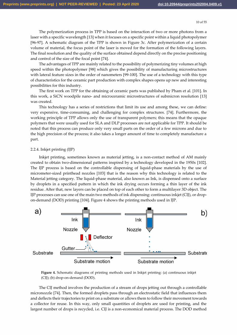
on-demand (DOD) printing [104]. Figure 4 shows the printing methods used in IJP.
Figure 4. Schematic diagrams of printing methods used in Inkjet printing: (a) continuous inkjet
(CIJ); (b) drop-on-demand (DOD).
The CIJ method involves the production of a stream of drops jetting out through a controllable
micronozzle [74]. Then, the formed droplets pass through an electrostatic field that influences them
and deflects their trajectories to print on a substrate or allows them to follow their movement towards
a collector for reuse. In this way, only small quantities of droplets are used for printing, and the
largest number of drops is recycled, i.e. CIJ is a non-economical material process. The DOD method
Preprints (www.preprints.org) | NOT PEER-REVIEWED | Posted: 23 April 2020 doi:10.20944/preprints202004.0409.v1
11 of 55
produces ink droplets when and where it is required, thus this method is more economical than CIJ.
Moreover, the small size of droplets and the high positioning accuracy make it more ideal for 3D
printing [13]. In DOD the droplets can be formed by piezoelectric effect or thermal excitation in the
printing nozzle head [105]. Piezoelectric DOD utilizes a piezoelectric element located in the fluid
chamber near the nozzle head for the droplet formation [106]. In this case, the droplet is created and
ejected by a generating pressure pulse that forces the ink to leave the nozzle head [105]. The pressure
pulse is formed thanks to the piezoelectric element deformation under the application of a voltage.
When a droplet is ejected, it falls by the gravity then it impregnated in the subtracted thanks to the
momentum obtained during its movement [74]. After that, occurs the solvent evaporation from the
impregnated droplet creating a small layer made up of the ink residue. In thermal DOD process,
sometimes named as bubble jet printing [74], a thermal excitation for the formation of the droplets
and ejecting is used. The thermal excitation is generated when a pulse current crosses through a
heating element that is located in the fluid chamber near the nozzle head and direct contact with the
ink. When the temperature of the heater element reaches the ink’s boiling point rapid ink
vaporization is occurred creating a bubble. This bubble formation is followed by a very fast collapse
when the pulse current source is “switched off”.
Different types of materials as polymers or metals for electronic patterning [107], solder paste
for microelectronics soldering [108] and cells for restoration in tissue engineering [109] were used in
IJP. However, the IJP method is limited only to the production of miniaturized parts due to the low
ink volume used in each droplet [13]. The obtaining of a solid ceramic part after an IJP process
involves the drying and sintering post-processing of the printed part.
Thanks to the development of computational technologies, the increase in positioning precision
and advances in the 3D printing field, the use of the IJP method has been achieved for ceramic
materials dispersed in liquid solvents [13]. The first report of IJP with ceramic materials dates back
to 1995 [110] when Blazdell et al. used ceramic inks (ZrO2 and TiO2) with a volumetric fraction of 5%.
After that, different researches groups improved the IJP and the feedstock preparation for obtaining
materials with ceramic loading until 40% [111-112].
2.3. Bulk solid-based
This group of AM technologies for ceramic materials involves the methods that use material
sheets, semi-molten [74] or semi-liquid systems [13] in which fine ceramic particles are well dispersed
as feedstock. Note that semi-molten and semi-liquid systems, commonly of ceramic/polymer
mixtures, have a high-viscosity in the range of some Pa·s like pastes with a greater ceramic loading
(up to 60 vol%) [13]. In this group, some AM technologies that belong to different categories such as
Sheet lamination or Material Extrusion will be considered. Among the AM technologies that utilize
solid feedstock for ceramic materials are laminated object manufacturing (LOM), Fused Deposition
Modeling (FDM), and direct ink writing (DIW) that are the most important in the industry [13,72].
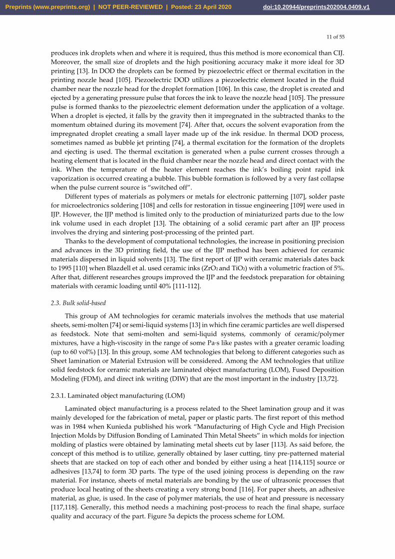
2.3.1. Laminated object manufacturing (LOM)
Laminated object manufacturing is a process related to the Sheet lamination group and it was
mainly developed for the fabrication of metal, paper or plastic parts. The first report of this method
was in 1984 when Kunieda published his work “Manufacturing of High Cycle and High Precision
Injection Molds by Diffusion Bonding of Laminated Thin Metal Sheets” in which molds for injection
molding of plastics were obtained by laminating metal sheets cut by laser [113]. As said before, the
concept of this method is to utilize, generally obtained by laser cutting, tiny pre-patterned material
sheets that are stacked on top of each other and bonded by either using a heat [114,115] source or
adhesives [13,74] to form 3D parts. The type of the used joining process is depending on the raw
material. For instance, sheets of metal materials are bonding by the use of ultrasonic processes that
produce local heating of the sheets creating a very strong bond [116]. For paper sheets, an adhesive
material, as glue, is used. In the case of polymer materials, the use of heat and pressure is necessary
[117,118]. Generally, this method needs a machining post-process to reach the final shape, surface
quality and accuracy of the part. Figure 5a depicts the process scheme for LOM.
Preprints (www.preprints.org) | NOT PEER-REVIEWED | Posted: 23 April 2020 doi:10.20944/preprints202004.0409.v1
12 of 55
Laminated object manufacturing exhibit several advantages such as low process and machine
cost, high volumetric build rate, low material requirement, high surface finish and the ability to
obtaining parts of combination material and composites [119,74]. However, this technology has some
disadvantages such as the necessary use of tiny sheets of material, different bonding processes for
different types of materials and a non-high resolution of complex parts.
Only after 10 years that Kunieda published his work, the first report about LOM with ceramic
materials appeared [120,121]. The authors of this work, Griffin et al., used sheets of alumina and
zirconia for the manufacturing of solid parts with a high density after removing the binder and
sintering at high temperatures.
After Griffin's investigation, a large number of materials such as Al2O3 and SiC [122-125], binary
composites like ZrO2/Al2O3, Si/SiC, TiC/Ni [126-128], or more complex systems, for example, LiO2–
ZrO2–SiO2–Al2O3 (LZSA) glass-ceramic composite [129] have been investigated for they use in LOM.
Despite the great effort made in the study of ceramics for LOM, in recent years no progress has
been observed in this field. Thus, the application of this technique is restricted only for the
manufacture of ceramic parts with simple geometry, and large sizes, which create a problem for its
application in the production of advanced ceramic components that, are generally characterized by
their complex geometry and much times for its miniature sizes.
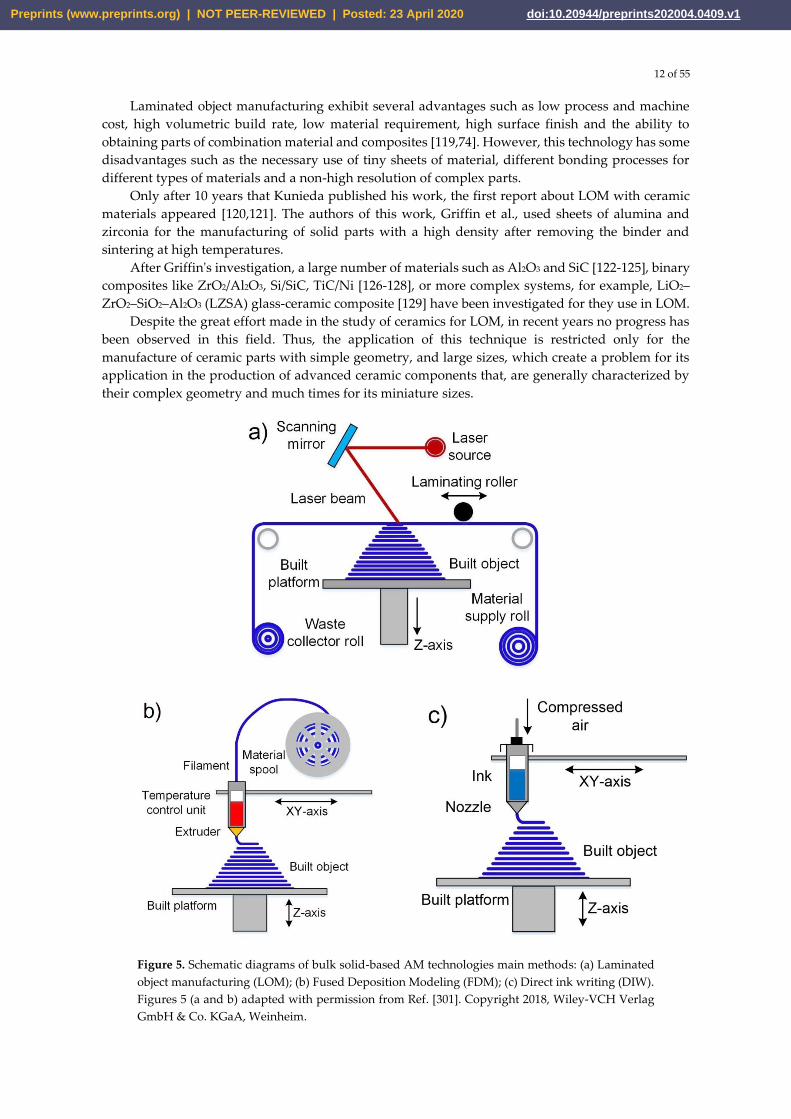
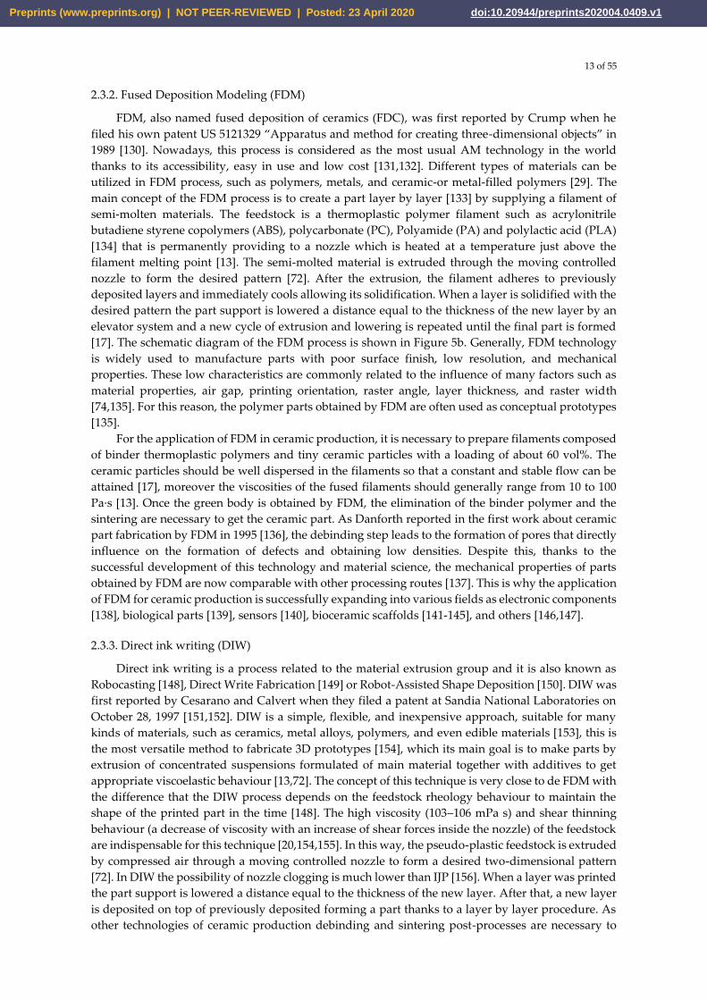
Figure 5. Schematic diagrams of bulk solid-based AM technologies main methods: (a) Laminated
object manufacturing (LOM); (b) Fused Deposition Modeling (FDM); (c) Direct ink writing (DIW).
Figures 5 (a and b) adapted with permission from Ref. [301]. Copyright 2018, Wiley‐VCH Verlag
GmbH & Co. KGaA, Weinheim.
Preprints (www.preprints.org) | NOT PEER-REVIEWED | Posted: 23 April 2020 doi:10.20944/preprints202004.0409.v1
13 of 55
2.3.2. Fused Deposition Modeling (FDM)
FDM, also named fused deposition of ceramics (FDC), was first reported by Crump when he
filed his own patent US 5121329 “Apparatus and method for creating three-dimensional objects” in
1989 [130]. Nowadays, this process is considered as the most usual AM technology in the world
thanks to its accessibility, easy in use and low cost [131,132]. Different types of materials can be
utilized in FDM process, such as polymers, metals, and ceramic-or metal-filled polymers [29]. The
main concept of the FDM process is to create a part layer by layer [133] by supplying a filament of
semi-molten materials. The feedstock is a thermoplastic polymer filament such as acrylonitrile
butadiene styrene copolymers (ABS), polycarbonate (PC), Polyamide (PA) and polylactic acid (PLA)
[134] that is permanently providing to a nozzle which is heated at a temperature just above the
filament melting point [13]. The semi-molted material is extruded through the moving controlled
nozzle to form the desired pattern [72]. After the extrusion, the filament adheres to previously
deposited layers and immediately cools allowing its solidification. When a layer is solidified with the
desired pattern the part support is lowered a distance equal to the thickness of the new layer by an
elevator system and a new cycle of extrusion and lowering is repeated until the final part is formed
[17]. The schematic diagram of the FDM process is shown in Figure 5b. Generally, FDM technology
is widely used to manufacture parts with poor surface finish, low resolution, and mechanical
properties. These low characteristics are commonly related to the influence of many factors such as
material properties, air gap, printing orientation, raster angle, layer thickness, and raster width
[74,135]. For this reason, the polymer parts obtained by FDM are often used as conceptual prototypes
[135].
For the application of FDM in ceramic production, it is necessary to prepare filaments composed
of binder thermoplastic polymers and tiny ceramic particles with a loading of about 60 vol%. The
ceramic particles should be well dispersed in the filaments so that a constant and stable flow can be
attained [17], moreover the viscosities of the fused filaments should generally range from 10 to 100
Pa·s [13]. Once the green body is obtained by FDM, the elimination of the binder polymer and the
sintering are necessary to get the ceramic part. As Danforth reported in the first work about ceramic
part fabrication by FDM in 1995 [136], the debinding step leads to the formation of pores that directly
influence on the formation of defects and obtaining low densities. Despite this, thanks to the
successful development of this technology and material science, the mechanical properties of parts
obtained by FDM are now comparable with other processing routes [137]. This is why the application
of FDM for ceramic production is successfully expanding into various fields as electronic components
[138], biological parts [139], sensors [140], bioceramic scaffolds [141-145], and others [146,147].
2.3.3. Direct ink writing (DIW)
Direct ink writing is a process related to the material extrusion group and it is also known as
Robocasting [148], Direct Write Fabrication [149] or Robot-Assisted Shape Deposition [150]. DIW was
first reported by Cesarano and Calvert when they filed a patent at Sandia National Laboratories on
October 28, 1997 [151,152]. DIW is a simple, flexible, and inexpensive approach, suitable for many
kinds of materials, such as ceramics, metal alloys, polymers, and even edible materials [153], this is
the most versatile method to fabricate 3D prototypes [154], which its main goal is to make parts by
extrusion of concentrated suspensions formulated of main material together with additives to get
appropriate viscoelastic behaviour [13,72]. The concept of this technique is very close to de FDM with
the difference that the DIW process depends on the feedstock rheology behaviour to maintain the
shape of the printed part in the time [148]. The high viscosity (103–106 mPa s) and shear thinning
behaviour (a decrease of viscosity with an increase of shear forces inside the nozzle) of the feedstock
are indispensable for this technique [20,154,155]. In this way, the pseudo-plastic feedstock is extruded
by compressed air through a moving controlled nozzle to form a desired two-dimensional pattern
[72]. In DIW the possibility of nozzle clogging is much lower than IJP [156]. When a layer was printed
the part support is lowered a distance equal to the thickness of the new layer. After that, a new layer
is deposited on top of previously deposited forming a part thanks to a layer by layer procedure. As
other technologies of ceramic production debinding and sintering post-processes are necessary to
Preprints (www.preprints.org) | NOT PEER-REVIEWED | Posted: 23 April 2020 doi:10.20944/preprints202004.0409.v1
14 of 55
obtain a ceramic part without organics. Figure 5c demonstrates a schematic diagram of the DIW
process.
This technology for ceramic materials, compared to SLA, is much faster and cheaper. The
exclusive use of ceramic pastes with required viscoelastic behaviour allows printing figures that can
maintain their original form regardless of the loads generated by the newly deposited layers on them.
Generally, the used pastes have a high loading of ceramic particles and optimal content of additives.
Thanks to this, it is possible to build parts with different configurations from complex porous
scaffolds [21], to composite materials [157] and solid monolithic parts [158]. Moreover, some
researchers could prepare and use for printing filaments with different cross-sectional forms [159,
160].
Thanks to the flexibility and simplicity of DIW, other scientists have been able to implement this
technology for the fabrication of parts with periodic structures [26,161], for electrodes for lithium-ion
(Li-ion) batteries [162, 163] and, in recent years, the manufacture of bioceramic implants [19,164,165].
The last is the prominent application thanks to/as a result of the porosities that appear in the part
after sintering. These porous structures are preferred in the manufacture of ceramic implants because
they promote the growth of human body tissue in them [167-169]. Thus, DIW is well suited to the
fabrication of tailored porous ceramic structures possessing periodic features, with little or no surface
resolution needed [13].
The aforementioned results show that DIW is a prominent technique for obtaining ceramic
pieces with complex geometry, but with the great disadvantage that it is not possible to obtain highly
dense pieces, which limits their application in the industry.
3. Additive Manufacturing for graphene-based materials
As previously stated, in the last few years AM technologies have become so popular throughout
the world that they have come to be applied in different fields of science and industry using different
types of materials such as polymers, metals, ceramics, and composites. At the same time, in the last
20 years the development of materials science, specifically in the area of nanotechnology, has allowed
the appearance, study, and development of interesting and perspective new materials, which are
known as nanomaterials, for their application in the industry [36,170]. Micro- and nanomaterials of
the same compound differ in that the latter can have exceptional and never-before-seen optical,
electronic, and mechanical properties in comparison with the first. The great interest in nanomaterials
is also because the properties of macro materials drastically change when nanomaterials are added
to their structure [171,172]. Thanks to this, many ceramic-based composites that have a certain
percentage of nanomaterials are converted into materials with improved mechanical properties. One
of these promising nanomaterials is graphene [173,174]. Graphene is a revolutionary material that
opens wide perspectives with its use, as an example, for increasing the flexural strength and fracture
toughness of ceramic materials [175, 176]. In the following sections, the characteristics and possible
applications of graphene-based material, as well as the most popular additive technologies for them,
will be explained in more detail.
3.1. Graphene and its derivatives materials
Graphene is a two-dimensional carbon allotropic form consisting of a single layer of sp2
hybridized atoms that are organized in a honeycomb lattice structure [177]. Graphene was discovered
in 2004 by Andre Geim and Konstantin Novoselov, who worked at the University of Manchester.
This material demonstrates unique properties such as very high thermal conductivity (above 5000 W
mK−1) [178,179], high modulus of elasticity (1 TPa) [180], large surface area (2630 m2/g) [181], high
electron mobility in room temperature (250.000 cm2/V s) [182] and high tensile strength of 130 GPa
[180]. Moreover, graphene shows high light transmittance [183], very high electrical conductivity
[184], and complete impermeability to any gases [185] that make it a very promising material for a
large number of multifunctional applications such as medicine [186], composite materials [187,188],
electronics [189], light processing [190], supercapacitors [191], energy [192], strain sensors [13] and
others [193,194].
Preprints (www.preprints.org) | NOT PEER-REVIEWED | Posted: 23 April 2020 doi:10.20944/preprints202004.0409.v1
15 of 55
Different methods of obtaining graphene have been investigated, but the most used are chemical
vapor deposition [195], epitaxial growth [196], the mechanical, oxidation-reduction method [197],
and liquid phase and electrochemical exfoliation [198]. It should be noted that the widespread use of
pristine graphene is limited mainly because it is hydrophobic [199]. The solution to this problem is
the surface functionalization of graphene that is carried out by chemical modification [200,201].
Generally, chemical modification of graphene can be done in two ways: covalent [202], or non-
covalent functionalization [203]. Functionalization via non-covalent interactions creates a weak
interaction of a π-π, van der Waals or electrostatic type between graphene and the target matter [201],
while the covalent modification use the covalent bonding of oxygen-containing functional groups on
the surface of graphene, forming carboxylic acid groups at the edges and epoxy and hydroxyl groups
at the basal plane [200]. Usually, researchers around the world use processes based on the Hummers
method, which are known as the modified Hummers method [204], for the covalent modification.
The main idea of the Hummers method is the use of very strong oxidizing agents, such as
concentrated sulfuric acid, nitric acid, and potassium permanganate, for the formation of oxygenated
functional groups on the graphite [205], which is then mechanically exfoliated to obtain fine sheets
of graphene with also functional groups on its surface [206]. This material is called Graphene Oxide
(GO) and it is hydrophilic that disperses easily in water [206].
The oxidation of graphene creates a large number of defects in its lattice structure that degrade
the material properties, moreover, the functional groups in the GO surface make it electrically
insulating [197,206]. Fortunately, a partial restore of graphene properties is possible thanks to a
reduction process of GO that can be carried out mainly by chemical or thermal ways, although other
less popular routes have also been used [197,206,207]. The idea of the reduction process is to remove
the functional groups from the GO surface to obtain reduced graphene oxide (rGO) by the application
of reducing agents [208] in the chemical reduction, or by a heat treatment in the thermal [153, 29].
Graphene and rGO differ from each other primarily by the presence of defects and some
functional groups that remained in their structure after the reduction process. This fact turns rGO
into a material with properties close to graphene and, at the same time, soluble in different media
that allows it to be used in industry [209]. For instance, a large number of graphene-based composites
have been created to improve the mechanical [210], thermal [211] and electrical [212] properties of
polymer matrices used with applications in aerospace, electronics, and energy storage [206,213,214].
Furthermore, graphene-based composites with inorganic matrices, such as metals, ceramics, and
composites have been developed [206,215-218].
3.2. Additive technologies for graphene-based materials
Like ceramic materials, graphene and its derivatives materials are also being studied to define
their role and use in AM [219]. Since graphene oxide is hydrophilic, it is the most suitable material to
be used as a precursor of graphene in additive technologies since this material can be easily dispersed
in different solvents, and especially in water. Thus, the appropriate AM techniques to be used with
graphene-based materials should belong to the categories vat photopolymerization, material jetting
and material extrusion. In this review, only the AM techniques that are more typical for the
production of graphene-based composites, in particular SLA, IJP, FDM, and DIW, will be analyzed.
Some of these methods are based on the use of polymers; and the introduction of graphene-based
material into them allows the obtaining of polymer nanocomposites with improved properties, for
example, barrier properties [185,220,221], optical properties [222,223], thermal properties [224-226],
electrical properties [227-229] and mechanical properties [224,230-232].
The final properties of polymer nanocomposites crucially depend on the effectiveness of the
nanoparticle dispersion process [233]. Thus, a good nanofillers dispersion in the polymer will
produce a maximum increase in the properties of the composite [234-237]. In many studies, the
process of preparing composites has been taken into account to obtain a high homogeneity and
dispersion of graphene-based materials within a polymer matrix [238]. The tactics implemented in
different works can be summarized in three strategies [233]: 1- In situ intercalative polymerization.
In this method, graphene or GO is first swollen in the liquid monomer, then a suitable initiator is
Preprints (www.preprints.org) | NOT PEER-REVIEWED | Posted: 23 April 2020 doi:10.20944/preprints202004.0409.v1
16 of 55
diffused and polymerization reaction proceeds by heat or radiation; 2 - Solution intercalation. Three
steps are involved in this method: dispersion of graphene or GO in a suitable solvent, the addition of
polymer and removal of the solvent. Graphene or GO can be dispersed in various solvents by
sonication. Then, the graphene-based-solution is mixed with the polymer matrix, which is adsorbed
onto the carbon sheets. Next, the carbon sheets sandwich the polymer to form a nanocomposite by
removing the solvent, which is crucial for the properties of nanocomposites. The main advantage of
this method is introducing low or even no polarity during the synthesis process; 3 - Melt intercalation.
Graphene or GO is mechanically mixed with thermoplastic polymer at elevated temperatures by
extrusion or injection molding. This method is solvent-free.
Of these three strategies the last two are the most widely used, while, as far as is known, the
literature on preparation of graphene-based polymer composites by in situ polymerization before
being extruded into filaments for FDM printing is still limited [29].
3.2.1. Stereolithography (SLA)
In section 2.2.1, the history facts, basic principles, advantages and disadvantages of this
technique were considered. In summary, SLA uses a liquid photopolymer that polymerizes under
the action of a UV light source to fabricate a part with a high resolution [239]. It is necessary to
consider two essential issues for SLA-based composites: (1) Rapid solidification of by light initiated
polymerization, which requests a fast light-responsive composite resin system; (2) Sufficient low
viscosity to allow for the dipping of the resin layer, which determines a low graphene content and
homogeneous filler distribution [240].
Over time, the SLA evolved and improved versions of this technique such as DLP, continuous
liquid interface production (CLIP), projection microstereolithography (PµSL) and TPP [82,241-243]
appeared. These modifications allow manufacturing parts with a higher resolution, shorter
manufacturing time and low post-process requirements [244].
In 2015, Lin et al. [233] reported the first manufacturing of GO reinforced complex architectures
by mask projection-based Stereolithography (MPSL), also called digital light processing (DLP), with
a good combination of strength and ductility. First of all, the expected weight amount of GO
nanosheets was sonicated in acetone and then they were dispersed in the polymer resin. This research
demonstrated that tensile strength and elongation of printed composite parts with only 0.2 wt% GO
increased by 62.2% and 12.8%, respectively. Moreover, this research group noticed a novel fracture
phenomenon of 3D printed truss architecture under the compression test. Later, in 2017 an
experiment was carried out by Manapat et al. [245] on the manufacture of high-strength
nanocomposites by a typical SLA process. In this work, the authors used the GO metastable structure
to improve the thermo-mechanical properties of a printed part that was then annealed at low
temperature. For this, composites with different GO contents (between 0 and 1 wt%) were prepared
by dispersing the GO in acetone and then mixing the as prepared dispersion with a resin. The
viscosities of the prepared GO resin varied between 0.6 and 1.6 Pa.s depending on the concentration
of GO. Before, the as-obtained GO resins were used to manufacture the 3D parts with an axial
resolution of 50 microns, which were then annealed at low temperatures (50 °C and 100 °C for 12
hours). The best results were obtained after annealing at 100°C for the 1 wt% GO nanocomposite that
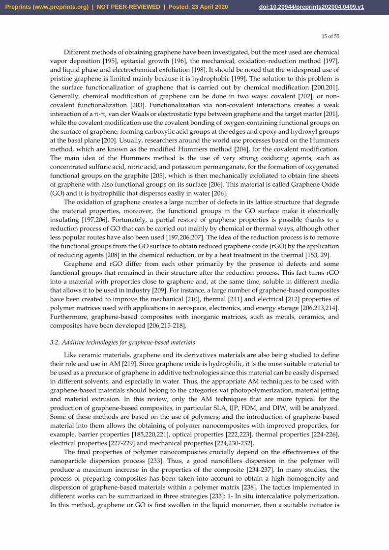
showed a very high increase of 673.6% on tensile strength compared with the casted material (Figure
6) [245].
Preprints (www.preprints.org) | NOT PEER-REVIEWED | Posted: 23 April 2020 doi:10.20944/preprints202004.0409.v1
17 of 55
Figure 6. a) Tensile strength comparison of casted and 3D-printed parts; SLA-printed complex-
shaped GO nanocomposites: (b) nested dodecahedron and (c) diagrid ring. Reprinted with
permission from [245]. Copyright (2017) American Chemical Society.
The previous work result shows that SLA is a good candidate to be used in the rapid
manufacturing of parts based on graphene reinforced composites that can be used in different
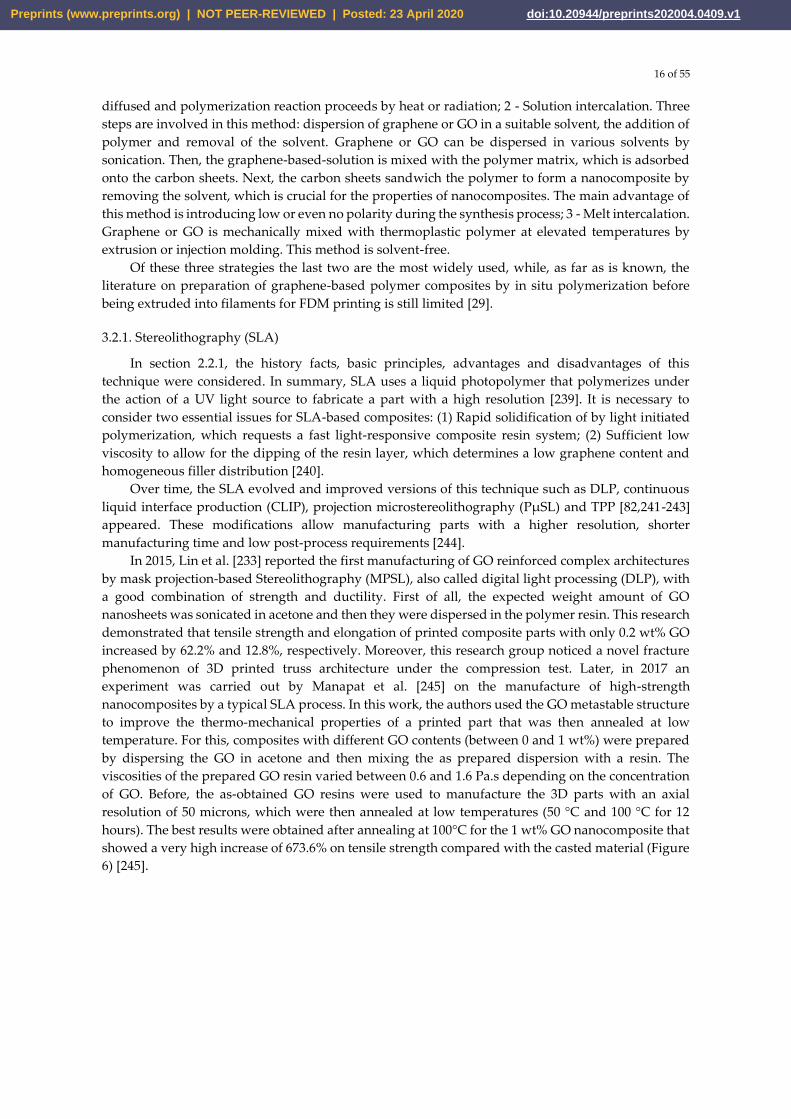
applications, such as in the biomedicine field. For example, in the work [246] published in 2018, a
graphene-reinforced composite for bone structure scaffolds was reported. Here, Feng et al. invented
a biodegradable UV-cured resin by SLA to create the personalized complex structure for bone tissue
scaffolds, which have been reinforced by the filling of graphene layers. The formulation consists of a
commercial polyurethane resin as an oligomer, trimethylolpropane trimethacrylate (TEGDMA) as a
reactive diluent and phenylbis (2, 4, 6-trimethylbenzoyl)-phosphine oxide (Irgacure 819) as a
photoinitiator. The obtained resin had suitable viscosities for SLA in the order of 847 Pa.s (at 25 °C)
and 500 Pa.s (at 30 °C). Thanks to the inclusion and the good dispersion of graphene fillers, the
manufactured parts by SLA had improved their mechanical properties when they are compared with
the conventional direct casting method. Thus, the tensile strength of the printed part rose to 68MPa
from 42MPa that is the value for the same material but produced by direct casting. Other
improvements are also been registered in the flexural strength (115 MPa) and flexural modulus (5.8
GPa). Consequently, these results show that this graphene-reinforced resin has a great ability for the
production of biological tissue engineering compared to the traditional mold-based multistep
methods that have a considerably low cost. Figure 7 [246] shows the images of jawbones, and gyroid
scaffolds of pure UV-cured resin and graphene-reinforced nanocomposite manufactured in this
work.
Preprints (www.preprints.org) | NOT PEER-REVIEWED | Posted: 23 April 2020 doi:10.20944/preprints202004.0409.v1
18 of 55
Figure 7. Images of (a) pure UV-cured resin and (b) graphene-reinforced nanocomposite jawbone
with a square architecture. Images of (c) pure UV-cured resin and (d) graphene-reinforced
nanocomposite gyroid scaffold for bone tissue engineering. Reproduced with permission from Ref.
[246]. Copyright © 2019 Zuying Feng et al.
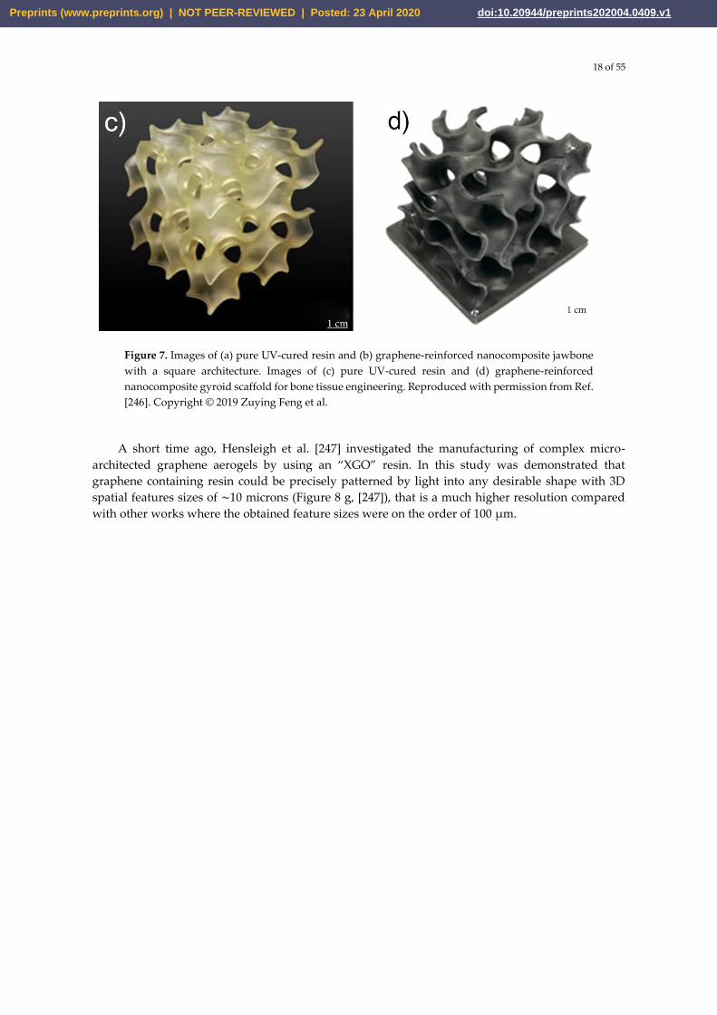
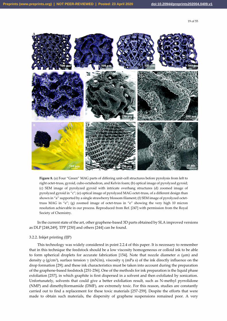
A short time ago, Hensleigh et al. [247] investigated the manufacturing of complex micro-
architected graphene aerogels by using an “XGO” resin. In this study was demonstrated that
graphene containing resin could be precisely patterned by light into any desirable shape with 3D
spatial features sizes of ∼10 microns (Figure 8 g, [247]), that is a much higher resolution compared
with other works where the obtained feature sizes were on the order of 100 µm.
Preprints (www.preprints.org) | NOT PEER-REVIEWED | Posted: 23 April 2020 doi:10.20944/preprints202004.0409.v1
19 of 55
Figure 8. (a) Four “Green” MAG parts of differing unit-cell structures before pyrolysis from left to
right octet-truss, gyroid, cubo-octahedron, and Kelvin foam; (b) optical image of pyrolyzed gyroid;
(c) SEM image of pyrolyzed gyroid with intricate overhang structures (d) zoomed image of
pyrolyzed gyroid in “c”; (e) optical image of pyrolyzed MAG octet-truss, of a different design than
shown in “a” supported by a single strawberry blossom filament; (f) SEM image of pyrolyzed octet-
truss MAG in “e”; (g) zoomed image of octet-truss in “e” showing the very high 10 micron
resolution achievable in our process. Reproduced from Ref. [247] with permission from the Royal
Society of Chemistry.
In the current state of the art, other graphene-based 3D parts obtained by SLA improved versions
as DLP [248,249], TPP [250] and others [244] can be found.
3.2.2. Inkjet printing (IJP)
This technology was widely considered in point 2.2.4 of this paper. It is necessary to remember
that in this technique the feedstock should be a low viscosity homogeneous or colloid ink to be able
to form spherical droplets for accurate fabrication [154]. Note that nozzle diameter α (µm) and
density ρ (g/cm3), surface tension γ (mN/m), viscosity η (mPa s) of the ink directly influence on the
drop formation [29]; and these ink characteristics must be taken into account during the preparation
of the graphene-based feedstock [251-256]. One of the methods for ink preparation is the liquid phase
exfoliation [257], in which graphite is first dispersed in a solvent and then exfoliated by sonication.
Unfortunately, solvents that could give a better exfoliation result, such as N-methyl pyrrolidone
(NMP) and dimethylformamide (DMF), are extremely toxic. For this reason, studies are constantly
carried out to find a replacement for these toxic materials [257-259]. Despite the efforts that were
made to obtain such materials, the dispersity of graphene suspensions remained poor. A very
Preprints (www.preprints.org) | NOT PEER-REVIEWED | Posted: 23 April 2020 doi:10.20944/preprints202004.0409.v1
20 of 55
practical way to stabilize the inks is to use GO or rGO together with surfactants that improve the
dispersity of sheets [257,260,261,262], thereby it reduces the probability of agglomerate formation in
graphene-based inks [257].
Different studies on IJP with graphene-based inks have been carried out, mainly for applications
in electronic, bioelectronic, and energy storage [263-268]. For example, in 2017 Li et al. [258] reported
a simple full-inkjet-printing technique for the scalable fabrication of graphene-based micro-
supercapacitors (MSCs) on various substrates. The authors prepared an ink based on high-
performance graphene with dimethylformamide (DMF) that had a concentration of 2.3 mg/mL of
graphene sheets and a stable period of more than half a year. This suspension was used for the
fabrication of tiny films (with thickness up to ∼0.7 µm) that served as both the electrodes and current
collectors. The fully printed graphene-based MSCs demonstrated an extremely high capacitance of
about 0.7 mF/cm2, which considerably exceeds the maximum value reached (∼0.1 mF/cm2) in printed
graphene-based MSCs [269,270] before this study. Moreover, the authors demonstrated that this
approach enabled the scalable fabrication of MSCs and effective connection in parallel and/or in series
at different scales [29], for instance, more than 100 devices have been connected to form large-scale
MSC arrays as power banks on both silicon wafers and Kapton. Without any extra protection or
encapsulation, the MSC arrays can be reliably charged up to 12 V and retain the performance even 8
months after fabrication.
Karim et al. [271] first reported an organic nanoparticle-based inkjet printable textile surface pre-
treatment which enables all inkjet-printed graphene-based wearable e-textiles. In this study, a way
to print a continuous conductive path on a rough and porous textile surface, which is the main
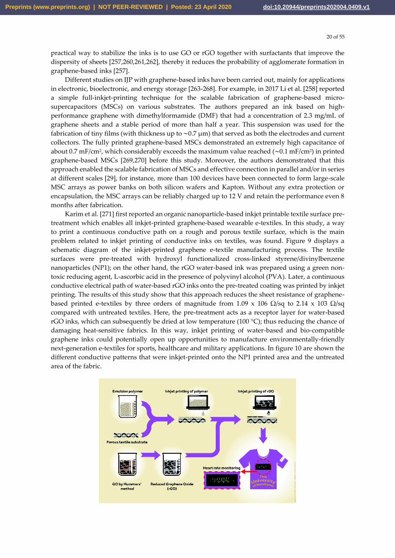
problem related to inkjet printing of conductive inks on textiles, was found. Figure 9 displays a
schematic diagram of the inkjet-printed graphene e-textile manufacturing process. The textile
surfaces were pre-treated with hydroxyl functionalized cross-linked styrene/divinylbenzene
nanoparticles (NP1); on the other hand, the rGO water-based ink was prepared using a green non-
toxic reducing agent, L-ascorbic acid in the presence of polyvinyl alcohol (PVA). Later, a continuous
conductive electrical path of water-based rGO inks onto the pre-treated coating was printed by inkjet
printing. The results of this study show that this approach reduces the sheet resistance of graphene-
based printed e-textiles by three orders of magnitude from 1.09 x 10⁶ Ω/sq to 2.14 x 10³ Ω/sq
compared with untreated textiles. Here, the pre-treatment acts as a receptor layer for water-based
rGO inks, which can subsequently be dried at low temperature (100 °C); thus reducing the chance of
damaging heat-sensitive fabrics. In this way, inkjet printing of water-based and bio-compatible
graphene inks could potentially open up opportunities to manufacture environmentally-friendly
next-generation e-textiles for sports, healthcare and military applications. In figure 10 are shown the
different conductive patterns that were inkjet-printed onto the NP1 printed area and the untreated
area of the fabric.
Preprints (www.preprints.org) | NOT PEER-REVIEWED | Posted: 23 April 2020 doi:10.20944/preprints202004.0409.v1
21 of 55
Figure 9. Schematic diagram of the inkjet-printed graphene e-textile manufacturing process.
Reproduced from Ref. [271] with permission from the Royal Society of Chemistry.
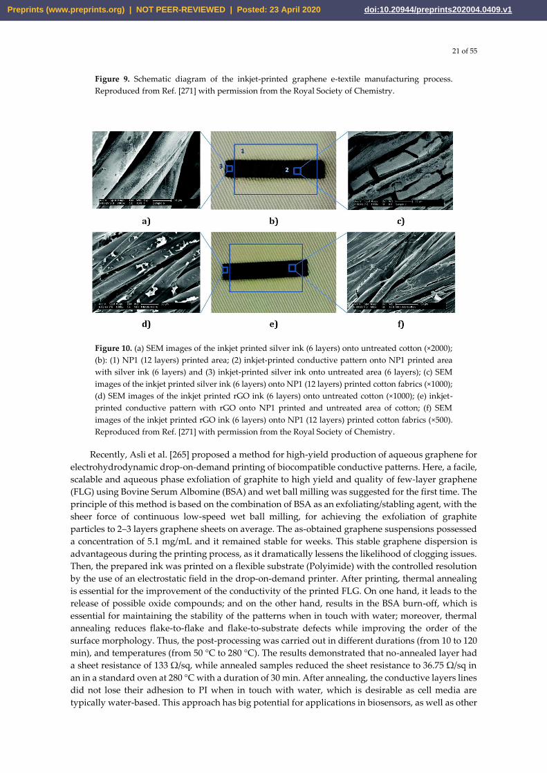
Figure 10. (a) SEM images of the inkjet printed silver ink (6 layers) onto untreated cotton (×2000);
(b): (1) NP1 (12 layers) printed area; (2) inkjet-printed conductive pattern onto NP1 printed area
with silver ink (6 layers) and (3) inkjet-printed silver ink onto untreated area (6 layers); (c) SEM
images of the inkjet printed silver ink (6 layers) onto NP1 (12 layers) printed cotton fabrics (×1000);
(d) SEM images of the inkjet printed rGO ink (6 layers) onto untreated cotton (×1000); (e) inkjet-
printed conductive pattern with rGO onto NP1 printed and untreated area of cotton; (f) SEM
images of the inkjet printed rGO ink (6 layers) onto NP1 (12 layers) printed cotton fabrics (×500).
Reproduced from Ref. [271] with permission from the Royal Society of Chemistry.
Recently, Asli et al. [265] proposed a method for high-yield production of aqueous graphene for
electrohydrodynamic drop-on-demand printing of biocompatible conductive patterns. Here, a facile,
scalable and aqueous phase exfoliation of graphite to high yield and quality of few-layer graphene
(FLG) using Bovine Serum Albomine (BSA) and wet ball milling was suggested for the first time. The
principle of this method is based on the combination of BSA as an exfoliating/stabling agent, with the
sheer force of continuous low-speed wet ball milling, for achieving the exfoliation of graphite
particles to 2–3 layers graphene sheets on average. The as-obtained graphene suspensions possessed
a concentration of 5.1 mg/mL and it remained stable for weeks. This stable graphene dispersion is
advantageous during the printing process, as it dramatically lessens the likelihood of clogging issues.
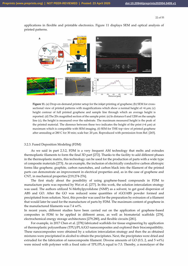
Then, the prepared ink was printed on a flexible substrate (Polyimide) with the controlled resolution
by the use of an electrostatic field in the drop-on-demand printer. After printing, thermal annealing
is essential for the improvement of the conductivity of the printed FLG. On one hand, it leads to the
release of possible oxide compounds; and on the other hand, results in the BSA burn-off, which is
essential for maintaining the stability of the patterns when in touch with water; moreover, thermal
annealing reduces flake-to-flake and flake-to-substrate defects while improving the order of the
surface morphology. Thus, the post-processing was carried out in different durations (from 10 to 120
min), and temperatures (from 50 °C to 280 °C). The results demonstrated that no-annealed layer had
a sheet resistance of 133 Ω/sq, while annealed samples reduced the sheet resistance to 36.75 Ω/sq in
an in a standard oven at 280 °C with a duration of 30 min. After annealing, the conductive layers lines
did not lose their adhesion to PI when in touch with water, which is desirable as cell media are
typically water-based. This approach has big potential for applications in biosensors, as well as other
Preprints (www.preprints.org) | NOT PEER-REVIEWED | Posted: 23 April 2020 doi:10.20944/preprints202004.0409.v1
22 of 55
applications in flexible and printable electronics. Figure 11 displays SEM and optical analysis of
printed patterns.
Figure 11. (a) Drop-on-demand printer setup for the inkjet printing of graphene; (b) SEM for cross-
sectional view of printed patterns with magnifications which show a normal height of ≈4 µm; (c)
height contour of full printed graphene and sample line through which an average height is
reported. (d) The 20x magnified section of the sample print. (e) In distance 0 and 1200 on the sample
line (c), the height is measured over the substrate. The maximum measured height is the peak of
the printed material. The dierence between these two indicates the height of the print (≈4 µm) at
maximum which is compatible with SEM imaging. (f) SEM for THE top view of printed graphene
after annealing at 280 C for 30 min; scale bar: 20 µm. Reproduced with permission from Ref. [265].
3.2.3. Fused Deposition Modeling (FDM)
As we said in part 2.3.2, FDM is a very frequent AM technology that melts and extrudes
thermoplastic filaments to form the final 3D part [272]. Thanks to the facility to add different phases
in the thermoplastic matrix, this technology can be used for the production of parts with a wide type
of composite materials [273]. As an example, the inclusion of electrically conductive carbon allotropic
forms like graphene, graphite, carbon nanotubes, and carbon black into the filament of the printed
parts can demonstrate an improvement in electrical properties and, as in the case of graphene and
CNT, in mechanical properties [219,274-276].
The first study about the possibility of using graphene-based compounds in FDM to
manufacture parts was reported by Wei et al. [277]. In this work, the solution intercalation strategy
was used. The authors utilized N-Methylpyrolidone (NMP) as a solvent, to get good dispersion of
ABS and GO. After the GO was reduced some quantities of rGO/ABS powder formed and
precipitated from solution. Next, this powder was used for the preparation by extrusion of a filament
that would later be used for the manufacture of parts by FDM. The maximum content of graphene in
the manufactured filaments was 7.4 wt%.
In recent years, different studies have been carried out on the application of graphene-based
composites in FDM to be applied in different areas, as well as biomaterial scaffolds [278],
electrochemical energy storage architectures [279,280], and flexible circuits [281].
For example, in 2017 Chen et al. [278] fabricated scaffolds for tissue engineering by application
of thermoplastic polyurethane (TPU)/PLA/GO nanocomposites and explored their biocompatibility.
These nanocomposites were obtained by a solution intercalation strategy and then the as obtained
mixtures were precipitated in alcohol to obtain the precipitates. Next, the precipitates were dried and
extruded for the fabrication of nanocomposite filament. Diverse amounts of GO (0.5, 2, and 5 wt%)
were mixed with polymer with a fixed ratio of TPU/PLA equal to 7:3. Thereby, a monolayer of the
Preprints (www.preprints.org) | NOT PEER-REVIEWED | Posted: 23 April 2020 doi:10.20944/preprints202004.0409.v1
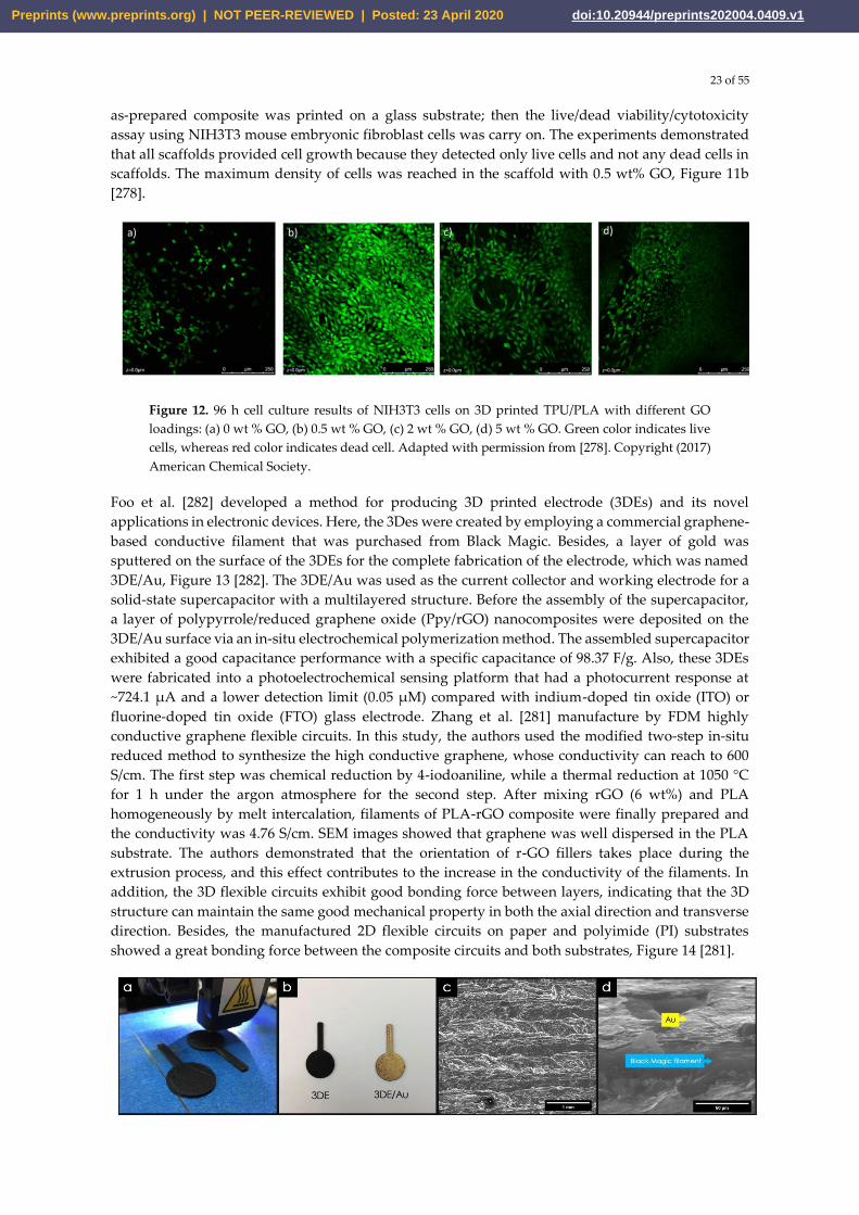
23 of 55
as-prepared composite was printed on a glass substrate; then the live/dead viability/cytotoxicity
assay using NIH3T3 mouse embryonic fibroblast cells was carry on. The experiments demonstrated
that all scaffolds provided cell growth because they detected only live cells and not any dead cells in
scaffolds. The maximum density of cells was reached in the scaffold with 0.5 wt% GO, Figure 11b
[278].
Figure 12. 96 h cell culture results of NIH3T3 cells on 3D printed TPU/PLA with different GO
loadings: (a) 0 wt % GO, (b) 0.5 wt % GO, (c) 2 wt % GO, (d) 5 wt % GO. Green color indicates live
cells, whereas red color indicates dead cell. Adapted with permission from [278]. Copyright (2017)
American Chemical Society.
Foo et al. [282] developed a method for producing 3D printed electrode (3DEs) and its novel
applications in electronic devices. Here, the 3Des were created by employing a commercial graphene-
based conductive filament that was purchased from Black Magic. Besides, a layer of gold was
sputtered on the surface of the 3DEs for the complete fabrication of the electrode, which was named
3DE/Au, Figure 13 [282]. The 3DE/Au was used as the current collector and working electrode for a
solid-state supercapacitor with a multilayered structure. Before the assembly of the supercapacitor,
a layer of polypyrrole/reduced graphene oxide (Ppy/rGO) nanocomposites were deposited on the
3DE/Au surface via an in-situ electrochemical polymerization method. The assembled supercapacitor
exhibited a good capacitance performance with a specific capacitance of 98.37 F/g. Also, these 3DEs
were fabricated into a photoelectrochemical sensing platform that had a photocurrent response at
~724.1 µA and a lower detection limit (0.05 µM) compared with indium-doped tin oxide (ITO) or
fluorine-doped tin oxide (FTO) glass electrode. Zhang et al. [281] manufacture by FDM highly
conductive graphene flexible circuits. In this study, the authors used the modified two-step in-situ
reduced method to synthesize the high conductive graphene, whose conductivity can reach to 600
S/cm. The first step was chemical reduction by 4-iodoaniline, while a thermal reduction at 1050 °C
for 1 h under the argon atmosphere for the second step. After mixing rGO (6 wt%) and PLA
homogeneously by melt intercalation, filaments of PLA-rGO composite were finally prepared and
the conductivity was 4.76 S/cm. SEM images showed that graphene was well dispersed in the PLA
substrate. The authors demonstrated that the orientation of r-GO fillers takes place during the
extrusion process, and this effect contributes to the increase in the conductivity of the filaments. In
addition, the 3D flexible circuits exhibit good bonding force between layers, indicating that the 3D
structure can maintain the same good mechanical property in both the axial direction and transverse
direction. Besides, the manufactured 2D flexible circuits on paper and polyimide (PI) substrates
showed a great bonding force between the composite circuits and both substrates, Figure 14 [281].
Preprints (www.preprints.org) | NOT PEER-REVIEWED | Posted: 23 April 2020 doi:10.20944/preprints202004.0409.v1
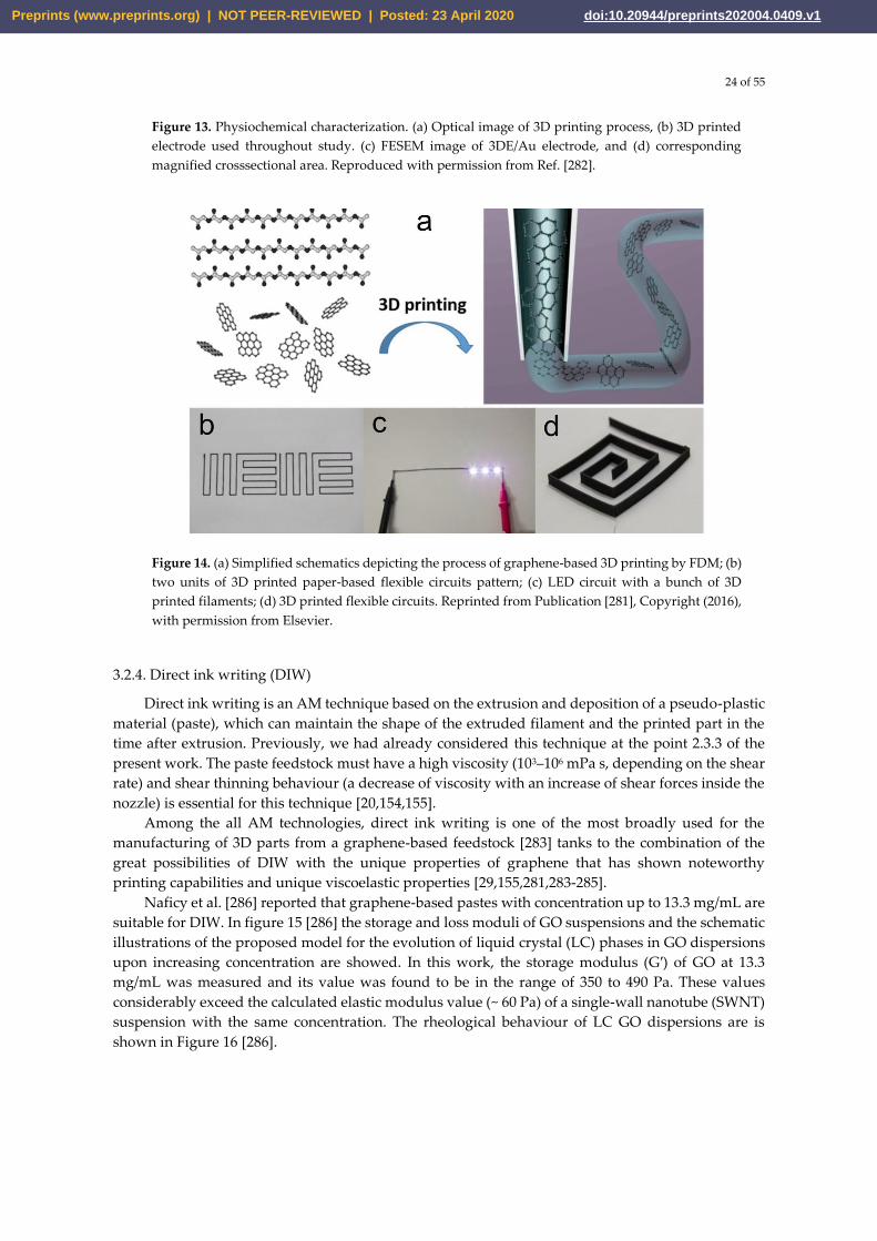
24 of 55
Figure 13. Physiochemical characterization. (a) Optical image of 3D printing process, (b) 3D printed
electrode used throughout study. (c) FESEM image of 3DE/Au electrode, and (d) corresponding
magnified crosssectional area. Reproduced with permission from Ref. [282].
Figure 14. (a) Simplified schematics depicting the process of graphene-based 3D printing by FDM; (b)
two units of 3D printed paper-based flexible circuits pattern; (c) LED circuit with a bunch of 3D
printed filaments; (d) 3D printed flexible circuits. Reprinted from Publication [281], Copyright (2016),
with permission from Elsevier.
3.2.4. Direct ink writing (DIW)
Direct ink writing is an AM technique based on the extrusion and deposition of a pseudo-plastic
material (paste), which can maintain the shape of the extruded filament and the printed part in the
time after extrusion. Previously, we had already considered this technique at the point 2.3.3 of the
present work. The paste feedstock must have a high viscosity (103–106 mPa s, depending on the shear
rate) and shear thinning behaviour (a decrease of viscosity with an increase of shear forces inside the
nozzle) is essential for this technique [20,154,155].
Among the all AM technologies, direct ink writing is one of the most broadly used for the
manufacturing of 3D parts from a graphene-based feedstock [283] tanks to the combination of the
great possibilities of DIW with the unique properties of graphene that has shown noteworthy
printing capabilities and unique viscoelastic properties [29,155,281,283-285].
Naficy et al. [286] reported that graphene-based pastes with concentration up to 13.3 mg/mL are
suitable for DIW. In figure 15 [286] the storage and loss moduli of GO suspensions and the schematic
illustrations of the proposed model for the evolution of liquid crystal (LC) phases in GO dispersions
upon increasing concentration are showed. In this work, the storage modulus (G′) of GO at 13.3
mg/mL was measured and its value was found to be in the range of 350 to 490 Pa. These values
considerably exceed the calculated elastic modulus value (~ 60 Pa) of a single-wall nanotube (SWNT)
suspension with the same concentration. The rheological behaviour of LC GO dispersions are is
shown in Figure 16 [286].
Preprints (www.preprints.org) | NOT PEER-REVIEWED | Posted: 23 April 2020 doi:10.20944/preprints202004.0409.v1
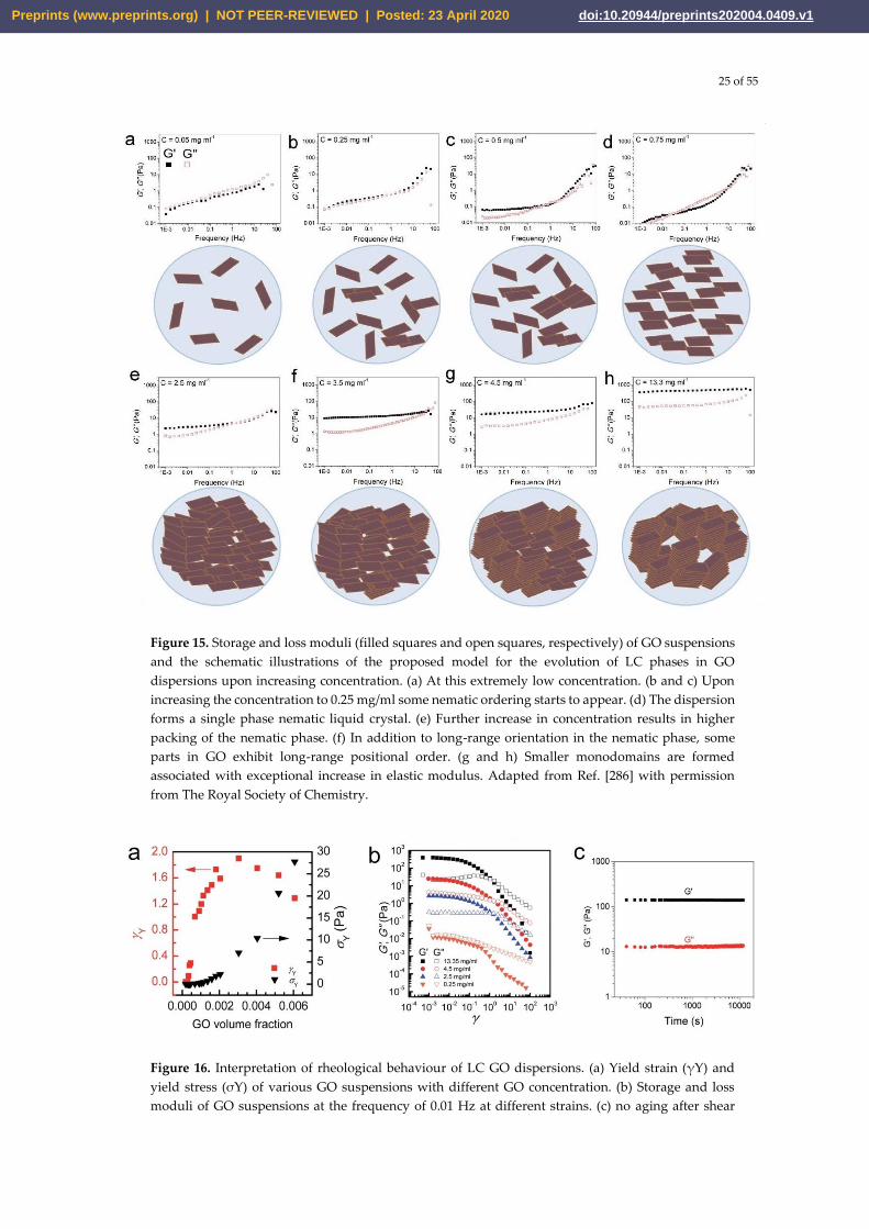
25 of 55
Figure 15. Storage and loss moduli (filled squares and open squares, respectively) of GO suspensions
and the schematic illustrations of the proposed model for the evolution of LC phases in GO
dispersions upon increasing concentration. (a) At this extremely low concentration. (b and c) Upon
increasing the concentration to 0.25 mg/ml some nematic ordering starts to appear. (d) The dispersion
forms a single phase nematic liquid crystal. (e) Further increase in concentration results in higher
packing of the nematic phase. (f) In addition to long-range orientation in the nematic phase, some
parts in GO exhibit long-range positional order. (g and h) Smaller monodomains are formed
associated with exceptional increase in elastic modulus. Adapted from Ref. [286] with permission
from The Royal Society of Chemistry.
Figure 16. Interpretation of rheological behaviour of LC GO dispersions. (a) Yield strain (γY) and
yield stress (σY) of various GO suspensions with different GO concentration. (b) Storage and loss
moduli of GO suspensions at the frequency of 0.01 Hz at different strains. (c) no aging after shear
Preprints (www.preprints.org) | NOT PEER-REVIEWED | Posted: 23 April 2020 doi:10.20944/preprints202004.0409.v1
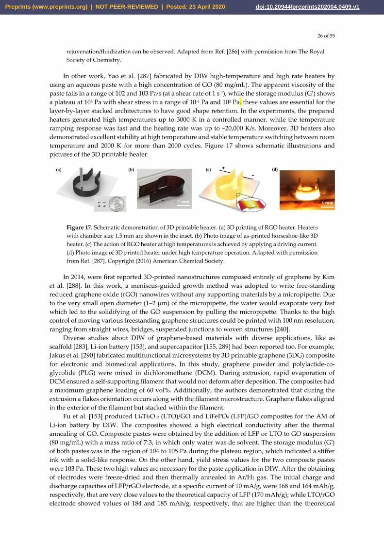
26 of 55
rejuvenation/fluidization can be observed. Adapted from Ref. [286] with permission from The Royal
Society of Chemistry.
In other work, Yao et al. [287] fabricated by DIW high-temperature and high rate heaters by
using an aqueous paste with a high concentration of GO (80 mg/mL). The apparent viscosity of the
paste falls in a range of 102 and 103 Pa·s (at a shear rate of 1 s-1), while the storage modulus (G′) shows
a plateau at 104 Pa with shear stress in a range of 10-1 Pa and 102 Pa. these values are essential for the
layer-by-layer stacked architectures to have good shape retention. In the experiments, the prepared
heaters generated high temperatures up to 3000 K in a controlled manner, while the temperature
ramping response was fast and the heating rate was up to ~20,000 K/s. Moreover, 3D heaters also
demonstrated excellent stability at high temperature and stable temperature switching between room
temperature and 2000 K for more than 2000 cycles. Figure 17 shows schematic illustrations and
pictures of the 3D printable heater.
Figure 17. Schematic demonstration of 3D printable heater. (a) 3D printing of RGO heater. Heaters
with chamber size 1.5 mm are shown in the inset. (b) Photo image of as-printed horseshoe-like 3D
heater. (c) The action of RGO heater at high temperatures is achieved by applying a driving current.
(d) Photo image of 3D printed heater under high temperature operation. Adapted with permission
from Ref. [287]. Copyright (2016) American Chemical Society.
In 2014, were first reported 3D-printed nanostructures composed entirely of graphene by Kim
et al. [288]. In this work, a meniscus-guided growth method was adopted to write free-standing
reduced graphene oxide (rGO) nanowires without any supporting materials by a micropipette. Due
to the very small open diameter (1–2 µm) of the micropipette, the water would evaporate very fast
which led to the solidifying of the GO suspension by pulling the micropipette. Thanks to the high
control of moving various freestanding graphene structures could be printed with 100 nm resolution,
ranging from straight wires, bridges, suspended junctions to woven structures [240].
Diverse studies about DIW of graphene-based materials with diverse applications, like as
scaffold [283], Li-ion battery [153], and supercapacitor [155, 289] had been reported too. For example,
Jakus et al. [290] fabricated multifunctional microsystems by 3D printable graphene (3DG) composite
for electronic and biomedical applications. In this study, graphene powder and polylactide-co-
glycolide (PLG) were mixed in dichloromethane (DCM). During extrusion, rapid evaporation of
DCM ensured a self-supporting filament that would not deform after deposition. The composites had
a maximum graphene loading of 60 vol%. Additionally, the authors demonstrated that during the
extrusion a flakes orientation occurs along with the filament microstructure. Graphene flakes aligned
in the exterior of the filament but stacked within the filament.
Fu et al. [153] produced Li4Ti5O12 (LTO)/GO and LiFePO4 (LFP)/GO composites for the AM of
Li-ion battery by DIW. The composites showed a high electrical conductivity after the thermal
annealing of GO. Composite pastes were obtained by the addition of LFP or LTO to GO suspension
(80 mg/mL) with a mass ratio of 7:3, in which only water was de solvent. The storage modulus (G′)
of both pastes was in the region of 104 to 105 Pa during the plateau region, which indicated a stiffer
ink with a solid-like response. On the other hand, yield stress values for the two composite pastes
were 103 Pa. These two high values are necessary for the paste application in DIW. After the obtaining
of electrodes were freeze-dried and then thermally annealed in Ar/H2 gas. The initial charge and
discharge capacities of LFP/rGO electrode, at a specific current of 10 mA/g, were 168 and 164 mAh/g,
respectively, that are very close values to the theoretical capacity of LFP (170 mAh/g); while LTO/rGO
electrode showed values of 184 and 185 mAh/g, respectively, that are higher than the theoretical
Preprints (www.preprints.org) | NOT PEER-REVIEWED | Posted: 23 April 2020 doi:10.20944/preprints202004.0409.v1
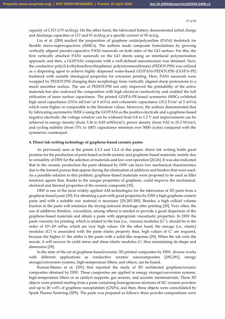
27 of 55
capacity of LTO (175 mAh/g). On the other hand, the fabricated battery demonstrated initial charge and discharge capacities of 117 and 91 mAh/g at a specific current of 50 mA/g.
Liu et al. [289] studied the preparation of graphene oxide/polyaniline (PANi) feedstock for flexible micro-supercapacitors (fMSCs). The authors made composite formulations by growing vertically aligned pseudo-capacitive PANi nanorods on both sides of the GO surface. For this, the first vertically attached PANi nanorods on the GO sheets using an interfacial polymerization approach; and then, a GO/PANi composite with a well-defined nanostructure was obtained. Next, the conductive poly(3,4-ethylenedioxythiophene): poly(styrenesulfonate) (PEDOT:PSS) was utilized as a dispersing agent to achieve highly dispersed water-based GO/PANi-PEDOT:PSS (GO/PA-PE) feedstock with suitable rheological properties for extrusion printing. Here, PANi nanorods were wrapped by PEDOT:PSS changing their morphology from vertically aligned sharp protrusions to a much smoother surface. The use of PEDOT:PSS not only improved the printability of the active materials but also endowed the composition with high electrical conductivity and enabled the full utilization of inner surface capacitance. The printed GO/PA-PE-based symmetric fMSCs exhibited high areal capacitance (153.6 mF/cm2 at 5 mV/s) and volumetric capacitance (19.2 F/cm3 at 5 mV/s) which were higher or comparable to the literature values. Moreover, the authors demonstrated that by fabricating asymmetric fMSCs using the GO/PANi as the positive electrode and a graphene-based negative electrode, the voltage window can be widened from 0.8 to 1.2 V and improvements can be achieved in energy density (from 3.36 to 4.83 mWh/cm3), power density (from 9.82 to 25.3 W/cm3), and cycling stability (from 75% to 100% capacitance retention over 5000 cycles) compared with the symmetric counterpart.
4. Direct ink writing technology of graphene-based ceramic pastes
As previously seen at the points 2.3.3 and 3.2.4 of this paper, direct ink writing holds great promise for the production of parts based on both ceramic and graphene-based materials, mainly due to versatility of DIW for the selection of materials and low-cost operation [20,26]. It was also indicated that in the ceramic production the parts obtained by DIW can have low mechanical characteristics due to the formed porous that appear during the elimination of additives and binders that were used. As a possible solution to this problem, graphene-based materials were proposed to be used as filler reinforce agents that, thanks to the unique properties of graphene, could improve the mechanical, electrical and thermal properties of the ceramic composite [35].
DIW is one of the most widely applied AM technologies for the fabrication of 3D parts from a graphene-based paste [29]. For obtaining a part with good properties by DIW a high graphene content paste and with a suitable raw material is necessary [29,283-285]. Besides, a high colloid volume fraction in the paste will minimize the drying-induced shrinkage after printing [29]. Very often, the use of additives (binders, viscosifiers, among others) is needed to provide a good dispersion of the graphene-based materials and obtain a paste with appropriate viscoelastic properties. In DIW the paste viscosity for printing, which is related to the loss (i.e., viscous) modulus (G’’), should be in the order of 103–106 mPas, which are very high values. On the other hand, the storage (i.e., elastic) modulus (G’) is associated with the paste elastic property thus, high values of G’ are required, because the higher G’ the stiffer is the paste with a solid-like response [29]. When the ink exits the nozzle, it will recover its yield stress and shear elastic modulus G′, thus maintaining its shape and dimension [29].
In the state of the art of graphene-based/ceramic 3D printed composites by DIW, diverse works
with different applications as conductive ceramic nanocomposites [285,291], energy
storage/conversion systems, high-temperature filters, and others, can be found.
Roman-Manso et al. [291] first reported the study of 3D architected graphene/ceramic
composites obtained by DIW. These composites are applied in energy storage/conversion systems,
high-temperature filters or as catalyst supports, gas sensors, and acoustic metamaterials. These 3D
objects were printed starting from a paste containing homogeneous mixtures of SiC ceramic powders
and up to 20 vol% of graphene nanoplatelets (GNPs), and then, these objects were consolidated by
Spark Plasma Sintering (SPS). The paste was prepared as follows: three powder compositions were
Preprints (www.preprints.org) | NOT PEER-REVIEWED | Posted: 23 April 2020 doi:10.20944/preprints202004.0409.v1
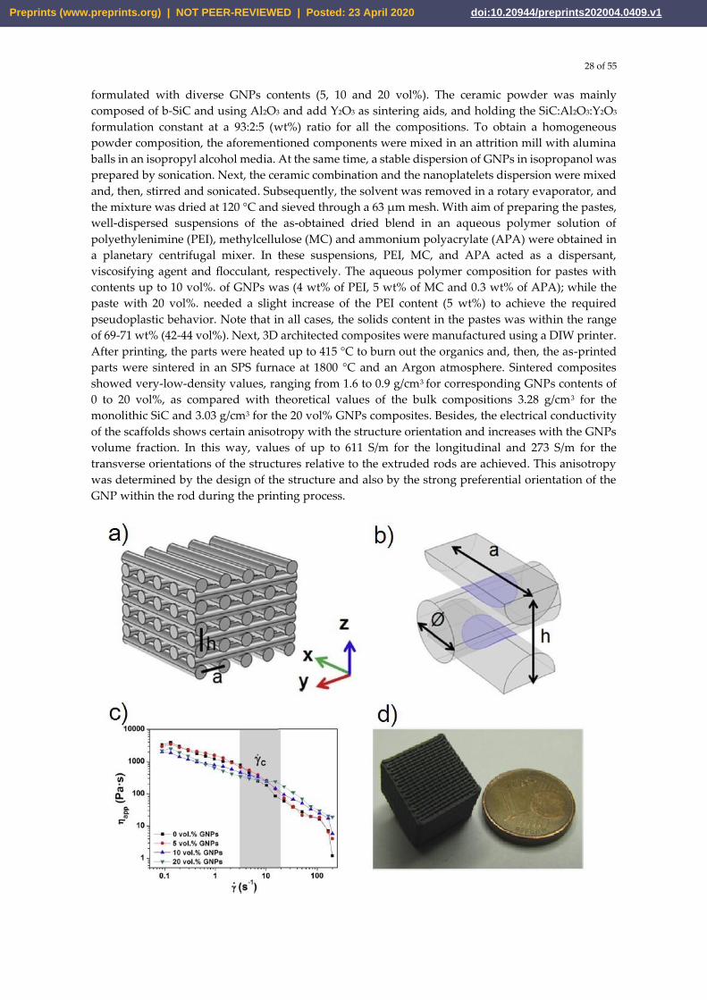
28 of 55
formulated with diverse GNPs contents (5, 10 and 20 vol%). The ceramic powder was mainly
composed of b-SiC and using Al2O3 and add Y2O3 as sintering aids, and holding the SiC:Al2O3:Y2O3
formulation constant at a 93:2:5 (wt%) ratio for all the compositions. To obtain a homogeneous
powder composition, the aforementioned components were mixed in an attrition mill with alumina
balls in an isopropyl alcohol media. At the same time, a stable dispersion of GNPs in isopropanol was
prepared by sonication. Next, the ceramic combination and the nanoplatelets dispersion were mixed
and, then, stirred and sonicated. Subsequently, the solvent was removed in a rotary evaporator, and
the mixture was dried at 120 °C and sieved through a 63 µm mesh. With aim of preparing the pastes,
well-dispersed suspensions of the as-obtained dried blend in an aqueous polymer solution of
polyethylenimine (PEI), methylcellulose (MC) and ammonium polyacrylate (APA) were obtained in
a planetary centrifugal mixer. In these suspensions, PEI, MC, and APA acted as a dispersant,
viscosifying agent and flocculant, respectively. The aqueous polymer composition for pastes with
contents up to 10 vol%. of GNPs was (4 wt% of PEI, 5 wt% of MC and 0.3 wt% of APA); while the
paste with 20 vol%. needed a slight increase of the PEI content (5 wt%) to achieve the required
pseudoplastic behavior. Note that in all cases, the solids content in the pastes was within the range
of 69-71 wt% (42-44 vol%). Next, 3D architected composites were manufactured using a DIW printer.
After printing, the parts were heated up to 415 °C to burn out the organics and, then, the as-printed
parts were sintered in an SPS furnace at 1800 °C and an Argon atmosphere. Sintered composites
showed very-low-density values, ranging from 1.6 to 0.9 g/cm3 for corresponding GNPs contents of
0 to 20 vol%, as compared with theoretical values of the bulk compositions 3.28 g/cm3 for the
monolithic SiC and 3.03 g/cm3 for the 20 vol% GNPs composites. Besides, the electrical conductivity
of the scaffolds shows certain anisotropy with the structure orientation and increases with the GNPs
volume fraction. In this way, values of up to 611 S/m for the longitudinal and 273 S/m for the
transverse orientations of the structures relative to the extruded rods are achieved. This anisotropy
was determined by the design of the structure and also by the strong preferential orientation of the
GNP within the rod during the printing process.
Preprints (www.preprints.org) | NOT PEER-REVIEWED | Posted: 23 April 2020 doi:10.20944/preprints202004.0409.v1
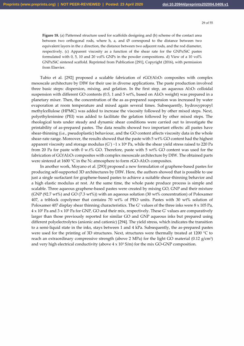
29 of 55
Figure 18. (a) Patterned structure used for scaffolds designing and (b) scheme of the contact area
between two orthogonal rods, where h, a, and Ø correspond to the distance between two
equivalent layers in the z direction, the distance between two adjacent rods, and the rod diameter,
respectively. (c) Apparent viscosity as a function of the shear rate for the GNPs/SiC pastes
formulated with 0, 5, 10 and 20 vol% GNPs in the powder compositions. d) View of a 10 vol%
GNPs/SiC sintered scaffold. Reprinted from Publication [291], Copyright (2016), with permission
from Elsevier.
Tubio et al. [292] proposed a scalable fabrication of rGO/Al2O3 composites with complex
mesoscale architecture by DIW for their use in diverse applications. The paste production involved
three basic steps: dispersion, mixing, and gelation. In the first step, an aqueous Al2O3 colloidal
suspension with different GO contents (0.5, 1 and 5 wt%, based on Al2O3 weight) was prepared in a
planetary mixer. Then, the concentration of the as as-prepared suspension was increased by water
evaporation at room temperature and mixed again several times. Subsequently, hydroxypropyl
methylcellulose (HPMC) was added to increase the viscosity followed by other mixed steps. Next,
polyethylenimine (PEI) was added to facilitate the gelation followed by other mixed steps. The
rheological tests under steady and dynamic shear conditions were carried out to investigate the
printability of as-prepared pastes. The data results showed two important effects: all pastes have
shear-thinning (i.e., pseudoplastic) behaviour, and the GO content affects viscosity data in the whole
shear-rate range. Moreover, the results showed that the paste with 5 wt% GO content had the highest
apparent viscosity and storage modulus (G’) ~1 x 10⁶ Pa, while the shear yield stress raised to 220 Pa
from 20 Pa for paste with 0 w.t% GO. Therefore, paste with 5 wt% GO content was used for the
fabrication of GO/Al2O3 composites with complex mesoscale architecture by DIW. The obtained parts
were sintered at 1600 °C in the N2 atmosphere to form rGO-Al2O3 composites.
In another work, Moyano et al. [293] proposed a new formulation of graphene-based pastes for
producing self-supported 3D architectures by DIW. Here, the authors showed that is possible to use
just a single surfactant for graphene-based pastes to achieve a suitable shear-thinning behavior and
a high elastic modulus at rest. At the same time, the whole paste produce process is simple and
scalable. Three aqueous graphene-based pastes were created by mixing GO, GNP and their mixture
(GNP (92.7 wt%) and GO (7.3 wt%)) with an aqueous solution (30 wt% concentration) of Poloxamer
407, a triblock copolymer that contains 70 wt% of PEO units. Pastes with 30 wt% solution of
Poloxamer 407 display shear thinning characteristics. The G’ values of the three inks were 8 x 10⁵ Pa,
4 x 10⁵ Pa and 3 x 10⁵ Pa for GNP, GO and their mix, respectively. These G' values are comparatively
larger than those previously reported for similar GO and GNP aqueous inks but prepared using
different polyelectrolytes (anionic and cationic) [294]. The yield stress, which indicates the transition
to a semi-liquid state in the inks, stays between 1 and 4 kPa. Subsequently, the as-prepared pastes
were used for the printing of 3D structures. Next, structures were thermally treated at 1200 °C to
reach an extraordinary compressive strength (above 2 MPa) for the light GO material (0.12 g/cm3)
and very high electrical conductivity (above 4 x 10³ S/m) for the mix GO-GNP composition.
Preprints (www.preprints.org) | NOT PEER-REVIEWED | Posted: 23 April 2020 doi:10.20944/preprints202004.0409.v1
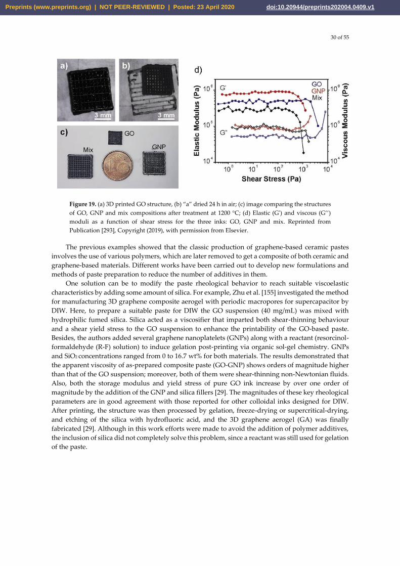
30 of 55
Figure 19. (a) 3D printed GO structure, (b) “a” dried 24 h in air; (c) image comparing the structures
of GO, GNP and mix compositions after treatment at 1200 °C; (d) Elastic (G') and viscous (G’’)
moduli as a function of shear stress for the three inks: GO, GNP and mix. Reprinted from
Publication [293], Copyright (2019), with permission from Elsevier.
The previous examples showed that the classic production of graphene-based ceramic pastes
involves the use of various polymers, which are later removed to get a composite of both ceramic and
graphene-based materials. Different works have been carried out to develop new formulations and
methods of paste preparation to reduce the number of additives in them.
One solution can be to modify the paste rheological behavior to reach suitable viscoelastic
characteristics by adding some amount of silica. For example, Zhu et al. [155] investigated the method
for manufacturing 3D graphene composite aerogel with periodic macropores for supercapacitor by
DIW. Here, to prepare a suitable paste for DIW the GO suspension (40 mg/mL) was mixed with
hydrophilic fumed silica. Silica acted as a viscosifier that imparted both shear-thinning behaviour
and a shear yield stress to the GO suspension to enhance the printability of the GO-based paste.
Besides, the authors added several graphene nanoplatelets (GNPs) along with a reactant (resorcinol-
formaldehyde (R-F) solution) to induce gelation post-printing via organic sol-gel chemistry. GNPs
and SiO2 concentrations ranged from 0 to 16.7 wt% for both materials. The results demonstrated that
the apparent viscosity of as-prepared composite paste (GO-GNP) shows orders of magnitude higher
than that of the GO suspension; moreover, both of them were shear-thinning non-Newtonian fluids.
Also, both the storage modulus and yield stress of pure GO ink increase by over one order of
magnitude by the addition of the GNP and silica fillers [29]. The magnitudes of these key rheological
parameters are in good agreement with those reported for other colloidal inks designed for DIW.
After printing, the structure was then processed by gelation, freeze-drying or supercritical-drying,
and etching of the silica with hydrofluoric acid, and the 3D graphene aerogel (GA) was finally
fabricated [29]. Although in this work efforts were made to avoid the addition of polymer additives,
the inclusion of silica did not completely solve this problem, since a reactant was still used for gelation
of the paste.
Preprints (www.preprints.org) | NOT PEER-REVIEWED | Posted: 23 April 2020 doi:10.20944/preprints202004.0409.v1
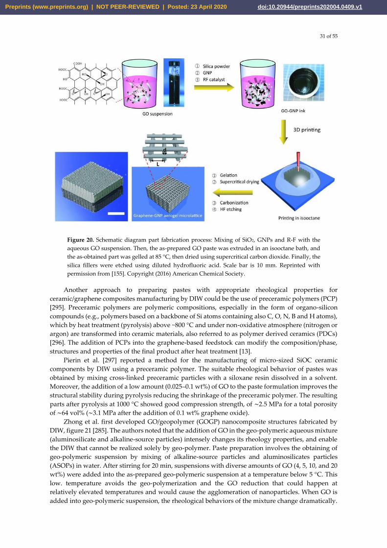
31 of 55
Figure 20. Schematic diagram part fabrication process: Mixing of SiO2, GNPs and R-F with the
aqueous GO suspension. Then, the as-prepared GO paste was extruded in an isooctane bath, and
the as-obtained part was gelled at 85 °C, then dried using supercritical carbon dioxide. Finally, the
silica fillers were etched using diluted hydrofluoric acid. Scale bar is 10 mm. Reprinted with
permission from [155]. Copyright (2016) American Chemical Society.
Another approach to preparing pastes with appropriate rheological properties for ceramic/graphene composites manufacturing by DIW could be the use of preceramic polymers (PCP) [295]. Preceramic polymers are polymeric compositions, especially in the form of organo-silicon compounds (e.g., polymers based on a backbone of Si atoms containing also C, O, N, B and H atoms), which by heat treatment (pyrolysis) above ~800 °C and under non-oxidative atmosphere (nitrogen or argon) are transformed into ceramic materials, also referred to as polymer derived ceramics (PDCs) [296]. The addition of PCPs into the graphene-based feedstock can modify the composition/phase, structures and properties of the final product after heat treatment [13].
Pierin et al. [297] reported a method for the manufacturing of micro-sized SiOC ceramic components by DIW using a preceramic polymer. The suitable rheological behavior of pastes was obtained by mixing cross-linked preceramic particles with a siloxane resin dissolved in a solvent. Moreover, the addition of a low amount (0.025–0.1 wt%) of GO to the paste formulation improves the structural stability during pyrolysis reducing the shrinkage of the preceramic polymer. The resulting parts after pyrolysis at 1000 °C showed good compression strength, of ∼2.5 MPa for a total porosity of ∼64 vol% (∼3.1 MPa after the addition of 0.1 wt% graphene oxide).
Zhong et al. first developed GO/geopolymer (GOGP) nanocomposite structures fabricated by DIW, figure 21 [285]. The authors noted that the addition of GO in the geo-polymeric aqueous mixture (aluminosilicate and alkaline-source particles) intensely changes its rheology properties, and enable the DIW that cannot be realized solely by geo-polymer. Paste preparation involves the obtaining of geo-polymeric suspension by mixing of alkaline-source particles and aluminosilicates particles (ASOPs) in water. After stirring for 20 min, suspensions with diverse amounts of GO (4, 5, 10, and 20 wt%) were added into the as-prepared geo-polymeric suspension at a temperature below 5 °C. This low. temperature avoids the geo-polymerization and the GO reduction that could happen at relatively elevated temperatures and would cause the agglomeration of nanoparticles. When GO is added into geo-polymeric suspension, the rheological behaviors of the mixture change dramatically.
Preprints (www.preprints.org) | NOT PEER-REVIEWED | Posted: 23 April 2020 doi:10.20944/preprints202004.0409.v1
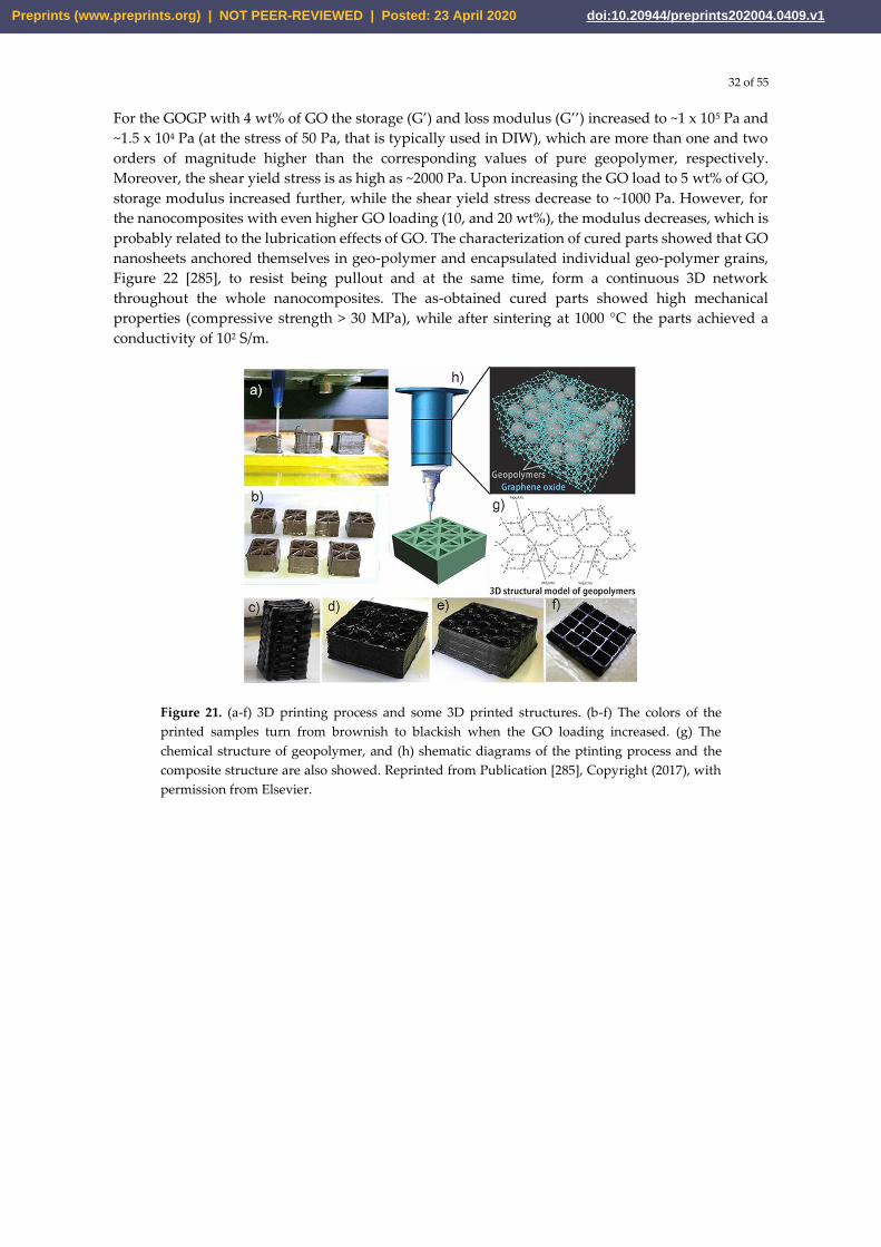
32 of 55
For the GOGP with 4 wt% of GO the storage (G’) and loss modulus (G’’) increased to ~1 x 10⁵ Pa and
~1.5 x 10⁴ Pa (at the stress of 50 Pa, that is typically used in DIW), which are more than one and two
orders of magnitude higher than the corresponding values of pure geopolymer, respectively.
Moreover, the shear yield stress is as high as ~2000 Pa. Upon increasing the GO load to 5 wt% of GO,
storage modulus increased further, while the shear yield stress decrease to ~1000 Pa. However, for
the nanocomposites with even higher GO loading (10, and 20 wt%), the modulus decreases, which is
probably related to the lubrication effects of GO. The characterization of cured parts showed that GO
nanosheets anchored themselves in geo-polymer and encapsulated individual geo-polymer grains,
Figure 22 [285], to resist being pullout and at the same time, form a continuous 3D network
throughout the whole nanocomposites. The as-obtained cured parts showed high mechanical
properties (compressive strength > 30 MPa), while after sintering at 1000 °C the parts achieved a
conductivity of 102 S/m.
Figure 21. (a-f) 3D printing process and some 3D printed structures. (b-f) The colors of the
printed samples turn from brownish to blackish when the GO loading increased. (g) The
chemical structure of geopolymer, and (h) shematic diagrams of the ptinting process and the
composite structure are also showed. Reprinted from Publication [285], Copyright (2017), with
permission from Elsevier.
Preprints (www.preprints.org) | NOT PEER-REVIEWED | Posted: 23 April 2020 doi:10.20944/preprints202004.0409.v1
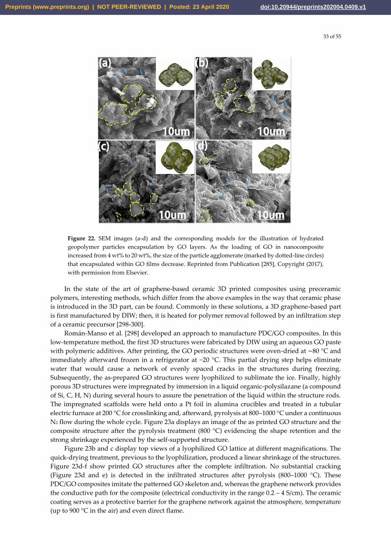
33 of 55
Figure 22. SEM images (a-d) and the corresponding models for the illustration of hydrated
geopolymer particles encapsulation by GO layers. As the loading of GO in nanocomposite
increased from 4 wt% to 20 wt%, the size of the particle agglomerate (marked by dotted-line circles)
that encapsulated within GO films decrease. Reprinted from Publication [285], Copyright (2017),
with permission from Elsevier.
In the state of the art of graphene-based ceramic 3D printed composites using preceramic
polymers, interesting methods, which differ from the above examples in the way that ceramic phase
is introduced in the 3D part, can be found. Commonly in these solutions, a 3D graphene-based part
is first manufactured by DIW; then, it is heated for polymer removal followed by an infiltration step
of a ceramic precursor [298-300].
Román-Manso et al. [298] developed an approach to manufacture PDC/GO composites. In this
low-temperature method, the first 3D structures were fabricated by DIW using an aqueous GO paste
with polymeric additives. After printing, the GO periodic structures were oven-dried at ∼80 °C and
immediately afterward frozen in a refrigerator at −20 °C. This partial drying step helps eliminate
water that would cause a network of evenly spaced cracks in the structures during freezing.
Subsequently, the as-prepared GO structures were lyophilized to sublimate the ice. Finally, highly
porous 3D structures were impregnated by immersion in a liquid organic-polysilazane (a compound
of Si, C, H, N) during several hours to assure the penetration of the liquid within the structure rods.
The impregnated scaffolds were held onto a Pt foil in alumina crucibles and treated in a tubular
electric furnace at 200 °C for crosslinking and, afterward, pyrolysis at 800–1000 °C under a continuous
N2 flow during the whole cycle. Figure 23a displays an image of the as printed GO structure and the
composite structure after the pyrolysis treatment (800 °C) evidencing the shape retention and the
strong shrinkage experienced by the self-supported structure.
Figure 23b and c display top views of a lyophilized GO lattice at different magnifications. The
quick-drying treatment, previous to the lyophilization, produced a linear shrinkage of the structures.
Figure 23d-f show printed GO structures after the complete infiltration. No substantial cracking
(Figure 23d and e) is detected in the infiltrated structures after pyrolysis (800–1000 °C). These
PDC/GO composites imitate the patterned GO skeleton and, whereas the graphene network provides
the conductive path for the composite (electrical conductivity in the range 0.2 – 4 S/cm). The ceramic
coating serves as a protective barrier for the graphene network against the atmosphere, temperature
(up to 900 °C in the air) and even direct flame.
Preprints (www.preprints.org) | NOT PEER-REVIEWED | Posted: 23 April 2020 doi:10.20944/preprints202004.0409.v1
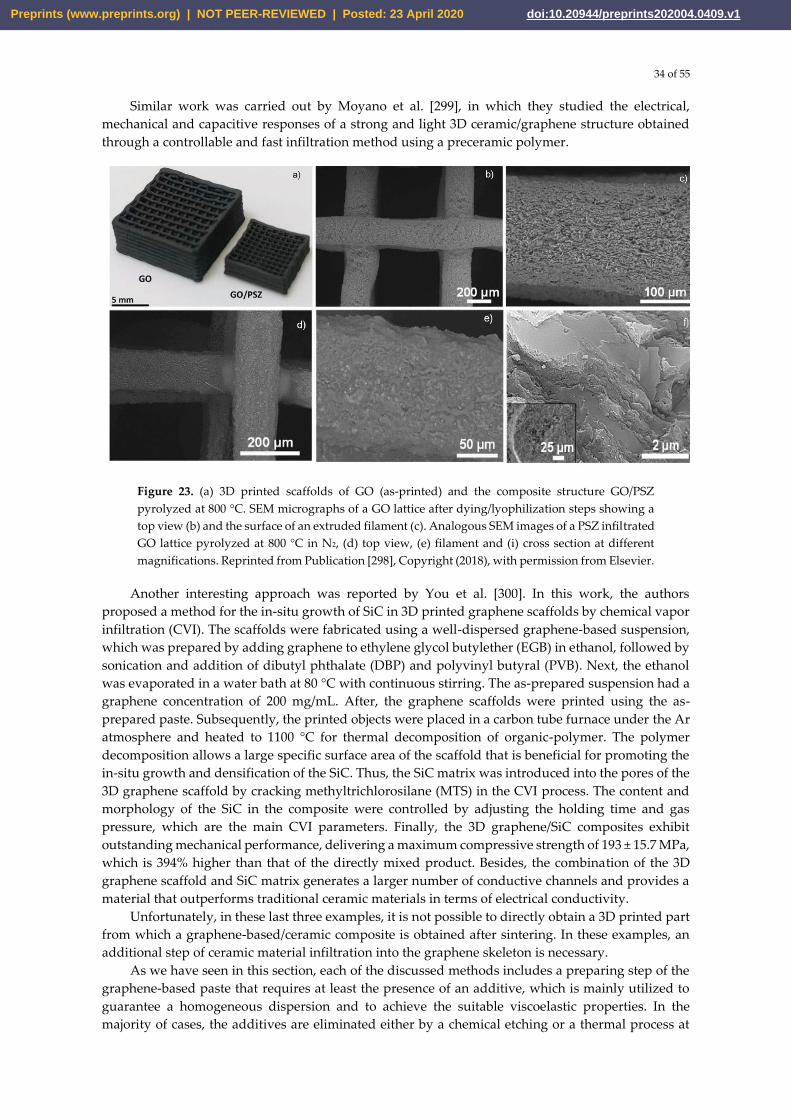
34 of 55
Similar work was carried out by Moyano et al. [299], in which they studied the electrical,
mechanical and capacitive responses of a strong and light 3D ceramic/graphene structure obtained
through a controllable and fast infiltration method using a preceramic polymer.
Figure 23. (a) 3D printed scaffolds of GO (as-printed) and the composite structure GO/PSZ
pyrolyzed at 800 °C. SEM micrographs of a GO lattice after dying/lyophilization steps showing a
top view (b) and the surface of an extruded filament (c). Analogous SEM images of a PSZ infiltrated
GO lattice pyrolyzed at 800 °C in N2, (d) top view, (e) filament and (i) cross section at different
magnifications. Reprinted from Publication [298], Copyright (2018), with permission from Elsevier.
Another interesting approach was reported by You et al. [300]. In this work, the authors
proposed a method for the in-situ growth of SiC in 3D printed graphene scaffolds by chemical vapor
infiltration (CVI). The scaffolds were fabricated using a well-dispersed graphene-based suspension,
which was prepared by adding graphene to ethylene glycol butylether (EGB) in ethanol, followed by
sonication and addition of dibutyl phthalate (DBP) and polyvinyl butyral (PVB). Next, the ethanol
was evaporated in a water bath at 80 °C with continuous stirring. The as-prepared suspension had a
graphene concentration of 200 mg/mL. After, the graphene scaffolds were printed using the as-
prepared paste. Subsequently, the printed objects were placed in a carbon tube furnace under the Ar
atmosphere and heated to 1100 °C for thermal decomposition of organic-polymer. The polymer
decomposition allows a large specific surface area of the scaffold that is beneficial for promoting the
in-situ growth and densification of the SiC. Thus, the SiC matrix was introduced into the pores of the
3D graphene scaffold by cracking methyltrichlorosilane (MTS) in the CVI process. The content and
morphology of the SiC in the composite were controlled by adjusting the holding time and gas
pressure, which are the main CVI parameters. Finally, the 3D graphene/SiC composites exhibit
outstanding mechanical performance, delivering a maximum compressive strength of 193 ± 15.7 MPa,
which is 394% higher than that of the directly mixed product. Besides, the combination of the 3D
graphene scaffold and SiC matrix generates a larger number of conductive channels and provides a
material that outperforms traditional ceramic materials in terms of electrical conductivity.
Unfortunately, in these last three examples, it is not possible to directly obtain a 3D printed part
from which a graphene-based/ceramic composite is obtained after sintering. In these examples, an
additional step of ceramic material infiltration into the graphene skeleton is necessary.
As we have seen in this section, each of the discussed methods includes a preparing step of the
graphene-based paste that requires at least the presence of an additive, which is mainly utilized to
guarantee a homogeneous dispersion and to achieve the suitable viscoelastic properties. In the
majority of cases, the additives are eliminated either by a chemical etching or a thermal process at
Preprints (www.preprints.org) | NOT PEER-REVIEWED | Posted: 23 April 2020 doi:10.20944/preprints202004.0409.v1
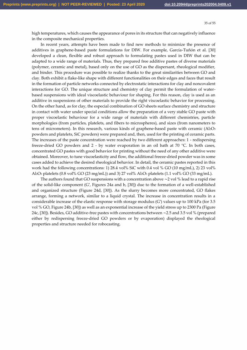
35 of 55
high temperatures, which causes the appearance of pores in its structure that can negatively influence
in the composite mechanical properties.
In recent years, attempts have been made to find new methods to minimize the presence of
additives in graphene-based paste formulations for DIW. For example, García-Tunon et al. [30]
developed a clean, flexible and robust approach to formulating pastes used in DIW that can be
adapted to a wide range of materials. Thus, they prepared free additive pastes of diverse materials
(polymer, ceramic and metal), based only on the use of GO as the dispersant, rheological modifier,
and binder. This procedure was possible to realize thanks to the great similarities between GO and
clay. Both exhibit a flake-like shape with different functionalities on their edges and faces that result
in the formation of particle networks connected by electrostatic interactions for clay and noncovalent
interactions for GO. The unique structure and chemistry of clay permit the formulation of water-
based suspensions with ideal viscoelastic behaviour for shaping. For this reason, clay is used as an
additive in suspensions of other materials to provide the right viscoelastic behavior for processing.
On the other hand, as for clay, the especial combination of GO sheets surface chemistry and structure
in contact with water under special conditions allow the preparation of a very stable GO paste with
proper viscoelastic behaviour for a wide range of materials with different chemistries, particle
morphologies (from particles, platelets, and fibers to microspheres), and sizes (from nanometers to
tens of micrometers). In this research, various kinds of graphene-based paste with ceramic (Al2O3
powders and platelets, SiC powders) were prepared and, then, used for the printing of ceramic parts.
The increases of the paste concentration were reached by two different approaches: 1 - redispersing
freeze-dried GO powders and 2 - by water evaporation in an oil bath at 70 °C. In both cases,
concentrated GO pastes with good behavior for printing without the need of any other additive were
obtained. Moreover, to tune viscoelasticity and flow, the additional freeze-dried powder was in some
cases added to achieve the desired rheological behavior. In detail, the ceramic pastes reported in this
work had the following concentrations: 1) 28.4 vol% SiC with 0.4 vol % GO (10 mg/mL), 2) 23 vol%
Al2O3 platelets (0.8 vol% GO (23 mg/mL)) and 3) 27 vol% Al2O3 platelets (1.1 vol% GO (33 mg/mL).
The authors found that GO suspensions with a concentration above ∼2 vol % lead to a rapid rise
of the solid-like component (G′, Figures 24a and b, [30]) due to the formation of a well-established
and organized structure (Figure 24d, [30]). As the slurry becomes more concentrated, GO flakes
arrange, forming a network, similar to a liquid crystal. The increase in concentration results in a
considerable increase of the elastic response with storage modulus (G′) values up to 100 kPa (for 3.5
vol % GO, Figure 24b, [30]) as well as an exponential increase of the yield stress up to 2300 Pa (Figure
24c, [30]). Besides, GO additive-free pastes with concentrations between ∼2.5 and 3.5 vol % (prepared
either by redispersing freeze-dried GO powders or by evaporation) displayed the rheological
properties and structure needed for robocasting.
Preprints (www.preprints.org) | NOT PEER-REVIEWED | Posted: 23 April 2020 doi:10.20944/preprints202004.0409.v1
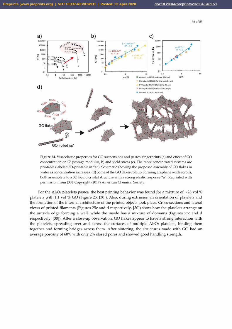
36 of 55
Figure 24. Viscoelastic properties for GO suspensions and pastes: fingerprints (a) and effect of GO
concentration on G′ (storage modulus, b) and yield stress (c). The more concentrated systems are
printable (labeled 3D-printable in “a”). Schematic showing the proposed assembly of GO flakes in
water as concentration increases. (d) Some of the GO flakes roll up, forming graphene oxide scrolls;
both assemble into a 3D liquid crystal structure with a strong elastic response “a”. Reprinted with
permission from [30]. Copyright (2017) American Chemical Society.
For the Al2O3 platelets pastes, the best printing behavior was found for a mixture of ∼28 vol %
platelets with 1.1 vol % GO (Figure 25, [30]). Also, during extrusion an orientation of platelets and
the formation of the internal architecture of the printed objects took place. Cross-sections and lateral
views of printed filaments (Figures 25c and d respectively, [30]) show how the platelets arrange on
the outside edge forming a wall, while the inside has a mixture of domains (Figures 25c and d
respectively, [30]). After a close-up observation, GO flakes appear to have a strong interaction with
the platelets, spreading over and across the surfaces of multiple Al2O3 platelets, binding them
together and forming bridges across them. After sintering, the structures made with GO had an
average porosity of 60% with only 2% closed pores and showed good handling strength.
Preprints (www.preprints.org) | NOT PEER-REVIEWED | Posted: 23 April 2020 doi:10.20944/preprints202004.0409.v1
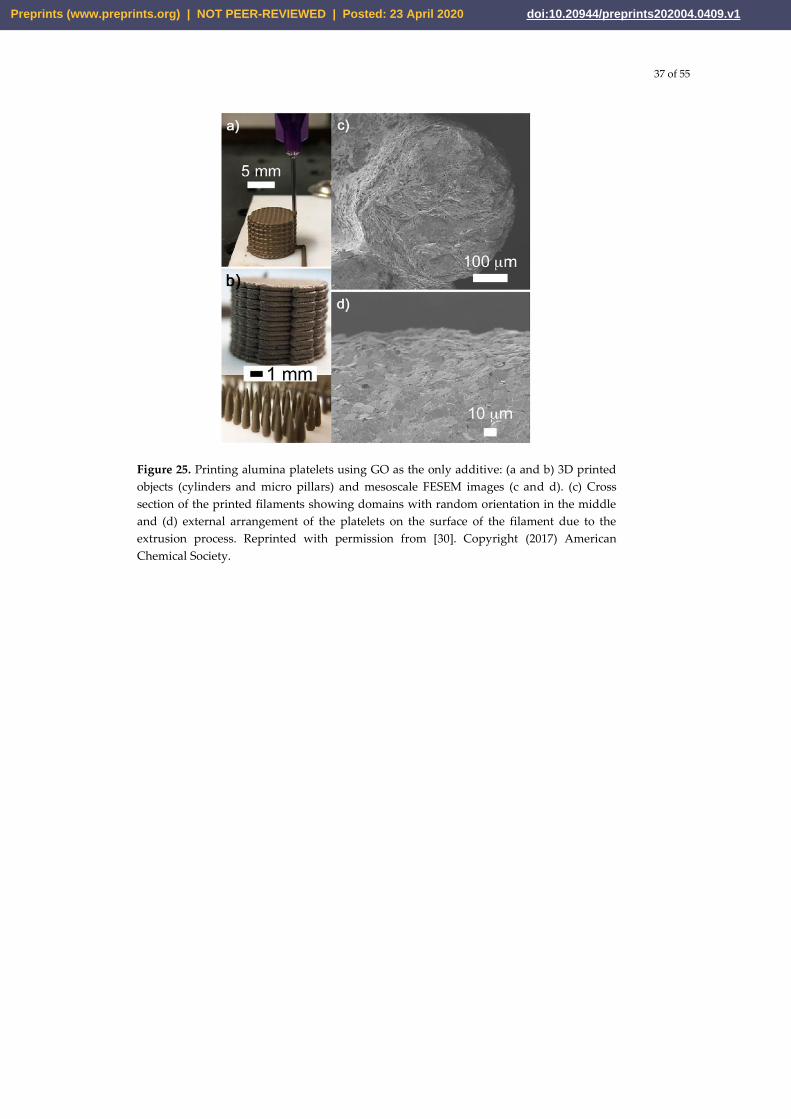
37 of 55
Figure 25. Printing alumina platelets using GO as the only additive: (a and b) 3D printed
objects (cylinders and micro pillars) and mesoscale FESEM images (c and d). (c) Cross
section of the printed filaments showing domains with random orientation in the middle
and (d) external arrangement of the platelets on the surface of the filament due to the
extrusion process. Reprinted with permission from [30]. Copyright (2017) American
Chemical Society.
Preprints (www.preprints.org) | NOT PEER-REVIEWED | Posted: 23 April 2020 doi:10.20944/preprints202004.0409.v1
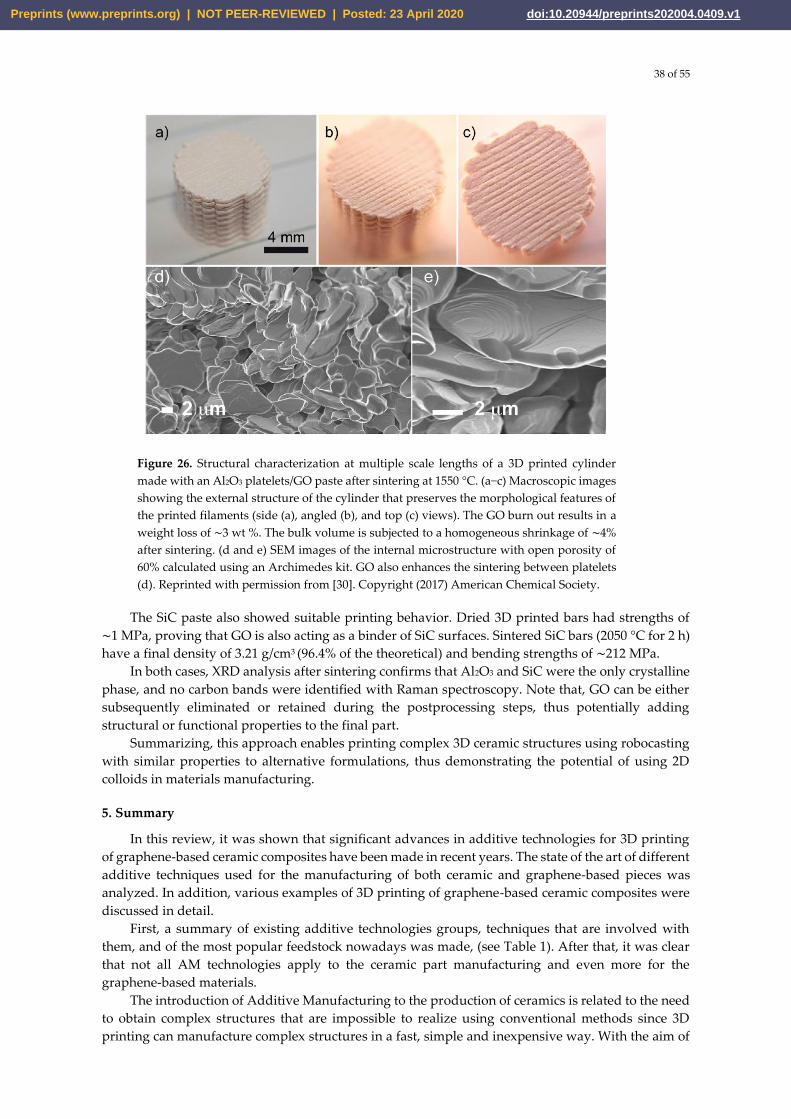
38 of 55
Figure 26. Structural characterization at multiple scale lengths of a 3D printed cylinder
made with an Al2O3 platelets/GO paste after sintering at 1550 °C. (a−c) Macroscopic images
showing the external structure of the cylinder that preserves the morphological features of
the printed filaments (side (a), angled (b), and top (c) views). The GO burn out results in a
weight loss of ∼3 wt %. The bulk volume is subjected to a homogeneous shrinkage of ∼4%
after sintering. (d and e) SEM images of the internal microstructure with open porosity of
60% calculated using an Archimedes kit. GO also enhances the sintering between platelets
(d). Reprinted with permission from [30]. Copyright (2017) American Chemical Society.
The SiC paste also showed suitable printing behavior. Dried 3D printed bars had strengths of
∼1 MPa, proving that GO is also acting as a binder of SiC surfaces. Sintered SiC bars (2050 °C for 2 h)
have a final density of 3.21 g/cm3 (96.4% of the theoretical) and bending strengths of ∼212 MPa.
In both cases, XRD analysis after sintering confirms that Al2O3 and SiC were the only crystalline
phase, and no carbon bands were identified with Raman spectroscopy. Note that, GO can be either
subsequently eliminated or retained during the postprocessing steps, thus potentially adding
structural or functional properties to the final part.
Summarizing, this approach enables printing complex 3D ceramic structures using robocasting
with similar properties to alternative formulations, thus demonstrating the potential of using 2D
colloids in materials manufacturing.
5. Summary
In this review, it was shown that significant advances in additive technologies for 3D printing
of graphene-based ceramic composites have been made in recent years. The state of the art of different
additive techniques used for the manufacturing of both ceramic and graphene-based pieces was
analyzed. In addition, various examples of 3D printing of graphene-based ceramic composites were
discussed in detail.
First, a summary of existing additive technologies groups, techniques that are involved with
them, and of the most popular feedstock nowadays was made, (see Table 1). After that, it was clear
that not all AM technologies apply to the ceramic part manufacturing and even more for the
graphene-based materials.
The introduction of Additive Manufacturing to the production of ceramics is related to the need
to obtain complex structures that are impossible to realize using conventional methods since 3D
printing can manufacture complex structures in a fast, simple and inexpensive way. With the aim of
Preprints (www.preprints.org) | NOT PEER-REVIEWED | Posted: 23 April 2020 doi:10.20944/preprints202004.0409.v1
39 of 55
a better understanding, the AM technologies used in ceramic production were divided into 3 groups
(powder-, slurry – and bulk solid-based) taking into account the type of feedstock used. The state of
the art of AM technologies that are involved with these groups has been discussed in detail and
illustrated with representative examples. Moreover, several historical facts about each technique
were given.
The techniques (SLS, SLM, and BJ.) are involved in the group of powder-based technologies for
the manufacture of 3D ceramic parts. SLS and SLM have a low surface finish, undesirable porosity,
and high shrinkage of parts that limit their application in many fields. Besides, the thermal gradients
and the high heating and cooling rates in the ceramic material produce cracks and distortions that
are not desired in the final part. On the other hand, in BJ the formation of pores and the contraction
of parts are related to the elimination of the binder used in the process. In BJ the mechanical properties
of parts are affected by pore formation, despite this, this technique is a good method used in
biomedical fields for the ceramic scaffold production.
The liquid-based group includes the SLA, DLP, TPP and IJP techniques. These methods proved
to be more promising than the powder-based ones as they can achieve high resolution, good surface
finish and required mechanical properties. Unfortunately, the high cost of the machines and the
photopolymers that are necessary for the manufacture of parts limit their wide application in the
industry. Furthermore, the working principle of TPP allows only the use of transparent polymers; i.e.
the opaque polymers that were usually utilized in SLA and DLP are not applicable for TPP. On the
other hand, IJP is limited only to the production of miniaturized parts due to the low ink volume
used in each droplet.
In the third group are LOM, FDM and DIW techniques. In recent years, great development of
the LOM technique has not been observed and its application has been restricted only for the
manufacture of ceramic parts with simple geometry, and large sizes. On the contrary, FDM and DIW
have found a great application in the manufacture of macro-pore structures for the biomedicine
application as the production of scaffolds.
AM techniques have also been used for 3D printing of graphene-based materials thanks to the
combination of its properties with the advantages of slurry-based methods and techniques that use a
pseudoplastic feedstock. Additionally, the choice of such technologies is related to the fact that
graphene oxide, the main precursor of graphene, can be easily dispersed in water and other solvents,
which is not possible with graphene. Among the most used methods for printing graphene-based
material, we can find SLA, IJP, FDM, and DIW techniques.
The SLA method has been utilized to manufacture polymer-based composites that are used in
the production of scaffolds in biomedicine. On the other hand, IJP is one of the most used techniques
in the printing of graphene-based materials despite the low resolution and limitations that it presents.
It is possible to found polymer-based filaments with graphene fillers for FDM that are used in the
production of parts for biomedicine or in electronics and other areas of application. The disadvantage
of this method is its low precision and the quality of the surface.
DIW is the most studied technique and one of the most widely used for the manufacture of 3D
parts from a graphene-based feedstock thanks to the combination of the great possibilities of DIW
with the unique properties of graphene that has demonstrated remarkable printing capabilities with
unique viscoelastic properties. For DIW, the rheology of the suspension is very important, so it is
essential to establish the appropriate content of the components to obtain their homogeneous
dispersion. After the part is printed, a subsequent process is necessary for the removal of the solvent,
which leads to the appearance of pores in the structure. Similar structures are widely used in the
production of biomaterial scaffolds and energy storage fields.
Finally, a detailed study with some examples of printed composites from graphene-based
ceramic pastes by DIW is carried out. In this field, there is a tendency to reduce the number of
additives that are used for obtaining a homogeneous dispersion and very often produce undesired
effects. Some examples show that it is possible the use preceramic polymers for the reduction of
additives and to perform the characteristics of printed composites. Of great importance is the work
carried out to create ceramic pastes without any other additives than graphene oxide. Here it is
Preprints (www.preprints.org) | NOT PEER-REVIEWED | Posted: 23 April 2020 doi:10.20944/preprints202004.0409.v1
40 of 55
appreciated how this material can be used as a dispersant, rheological modifier and binder at the
same time.
This work has tried to show that the DIW method is very promising in the printing of complex
graphene-based ceramic composites at reduced cost and in less time. We consider that this field
should continue to develop so that soon the manufacture of graphene-based ceramic composites will
take its place in the ceramic industry.
Author Contributions: Conceptualization, N.W.S.P., A.S.; data curation, N.P., A.Se.; formal analysis, N.W.S.P.,
N.P.; funding acquisition, P.P.; investigation, P.P., N.P.; methodology, A.S., N.W.S.P.; project administration,
N.W.S.P., P.P.; resources, N.W.S.P., N.P.; software, P.P., A.Se.; supervision, N.W.S.P., A.S.; validation, A.Se.,
N.P.; visualization, P.P., A.S. ; writing – original draft, N.W.S.P., A.S.
All authors read and approved the final version of the manuscript.
Funding: We would like to thank the Russian Science Foundation for supporting this work under grant 19-79-
00355.
Conflicts of Interest: The authors declare no conflict of interest.
References
[1] Kingery, W.D.; Bowen, H.K.; Uhlmann, D.R. Introduction to Ceramics, second edition. Wiley, NewYork
(1976), pp. 1-1056.
[2] C.B.; Norton, M.G. Ceramic Materials: Science and Engineering. Springer New York (2013), pp. 1-766.
[3] Smirnov, A.; Kurland, H.-D.; Grabow, J.; Müller, F.A.; Bartolomé, J.F. Microstructure, mechanical properties
and low temperature degradation resistance of 2Y-TZP ceramic materials derived from nanopowders prepared
by laser vaporization. J. Eur. Ceram. Soc. 2015, 35, 2685–2691.
[4] Smirnov, A.; Beltrán, J.I.; Rodriguez-Suarez, T.; Pecharromán, C.; Munoz, M.C.; Moya, J.S.; Bartolomé, J.F.
Unprecedented simultaneous enhancement in flaw tolerance and fatigue resistance of zirconia–Ta composites.
Sci. Rep. 2017, 7, 44922.
[5] Smirnov, A.; Bartolomé, J.F.; Kurland, H.-D.; Grabow, J.; Müller, F.A. Design of a new zirconia-alumina-Ta
micro-nanocomposite with unique mechanical properties. J. Am. Ceram. Soc. 2016, 99, 3205–3209.
[6] Bartolomé, J.F.; Smirnov, A.; Kurland, H.-D.; Grabow, J.; Müller, F.A. New ZrO2/Al2O3 Nanocomposites
Fabricated from Hybrid Nanoparticles Prepared by CO2 Laser Co-Vaporisation. Sci.Rep. 2016, 6, 20589.
[7] Microstructure and Mechanical Properties of ZrO2 Ceramics Toughened by 5–20 vol% Ta Metallic Particles
Fabricated by Pressureless Sintering. Ceram. Int. 2014, 40, 1829-1834.
[8] Gutierrez-Gonzalez, C.F.; Smirnov, A.; Bartolomé, J.F. Cyclic Fatigue Life- and Crack-Growth Behavior of
Zirconia-Niobium Composites. J. Am. Ceram. Soc. 2013, 96, 1709-1712.
[9] Bengisu, M. Engineering Ceramics. Springer-Verlag Berlin Heidelberg (2001), pp. XXI, 620.
[10] Richerson, D.W.; Lee, W.E. Modern Ceramic Engineering: Properties, Processing, and Use in Design, fourth
edition. CRC Press (2018), pp. 1-791.
[11] Fang, Z.Z. Sintering of Advanced Materials; fundamentals and processes. Woodhead Publishing (2010), pp.
1-483.
[12] Pristinskiy, Y.; Solis Pinargote, N.W.; Smirnov, A. The effect of MgO addition on the microstructure and
mechanical properties of alumina ceramic obtained by spark plasma sintering. In Materials today: proceedings
(2019), 19 (5), 1990-1993.
[13] Chen, Z.; Li, Z.; Li, J.; Liu, C.; Lao, C.; Fu, Y.; Liu, C.; Li, Y.; Wang, P.; He, Y. 3D printing of ceramics: A
review. J. Eur. Ceram. Soc. (2019), 39 (4), 661-687.
[14] Abdulhameed, O.; Al-Ahmari, A.; Ameen, W.; Mian, S.H. Additive manufacturing: Challenges, trends, and
applications. Advances in Mechanical Engineering (2019), 11 (2), 1–27.
Preprints (www.preprints.org) | NOT PEER-REVIEWED | Posted: 23 April 2020 doi:10.20944/preprints202004.0409.v1
41 of 55
[15] Gibson, I.; Rosen, D.; Stucker, B. Additive manufacturing technologies: 3D printing, rapid prototyping, and
direct digital manufacturing, second edition. Springer New York (2015), pp. 1–498.
[16] International Organization for Standardization. ISO/ASTM 52900:2015 [ASTM F2792] Additive
manufacturing — General principles — Terminology. Geneva: ISO; 2015.
[17] Shashi, G.M.; Laskar, M.A.R.; Biswas, H.; Saha, A.K. A Brief Review of Additive Manufacturing with
Applications Proceedings of 14th Global Engineering and Technology Conference 29-30 December 2017. Dhaka,
Bangladesh.
[18] Lewis, J.A.; Gratson, G.M. Direct writing in three dimensions. Mater. Today (2004), 7, 32–39.
[19] Martínez-Vázquez, F.J.; Perera, F.H.; Miranda, P.; Pajares, A.; Guiberteau, F. Improving the compressive
strength of bioceramic robocast scaffolds by polymer infiltration. Acta Biomater. (2010), 6, 4361–4368.
[20] Lewis, J.A. Direct ink writing of 3D functional materials. Adv. Funct. Mater. (2006), 16 (17), 2193–2204.
[21] Lewis, J.A.; Smay, J.E.; Stuecker, J.; Cesarano, J. Direct ink writing of three-dimensional ceramic structures.
J. Am. Ceram. Soc. (2006), 89 (12), 3599–3609.
[22] Revelo, C.F.; Colorado, H.A. 3D printing of kaolinite clay ceramics using the Direct Ink Writing (DIW)
technique. Ceram. Int. (2018), 44 (5), 5673–5682.
[23] Martínez-Vázquez, F.J.; Pajares, A.; Miranda P. A simple graphite-based support material for robocasting of
ceramic parts. J. Eur. Ceram. Soc. (2018), 38, 2247–2250.
[24] Ordonez, E.; Gallego, J. M.; Colorado, H.A. 3D printing via the direct ink writing technique of ceramic pastes
from typical formulations used in traditional ceramics industry. Applied Clay Science (2019), 182, 105285.
[25] Ahn, B. Y.; Duoss, E. B.; Motala, M. J.; Guo, X.; Park, S. I.; Xiong, Y.; Yoon, J.; Nuzzo, R. G.; Rogers, J. A.;
Lewis, J. A. Omnidirectional Printing of Flexible, Stretchable, and Spanning Silver Microelectrodes. Science
(2009), 323 (5921), 1590−1593.
[26] Smay, J. E.; Gratson, G. M.; Shepherd, R. F.; Cesarano, J.; Lewis, J. A. Directed Colloidal Assembly of 3D
Periodic Structures. Adv. Mater. (2002), 14 (18), 1279−1283.
[27] Heule, M.; Vuillemin, S.; Gauckler, L. J. Powder-Based Ceramic Meso- and Microscale Fabrication Processes.
Adv. Mater. (2003), 15 (15), 1237−1245.
[28] Liu, D.-M. Influence of porosity and pore size on the compressive strength of porous hydroxyapatite
ceramic. Ceram. Int. (1997), 23 (2), 135–139.
[29] Wang, J.; Liu, Y.; Fan, Z.; Wang, W.; Wang, B.; Guo Z. Ink-based 3D printing technologies for graphene-
based materials a review. Adv Compos Hybrid Mater (2019), 2, 1–33.
[30] García-Tunon, E.; Feilden, E.; Zheng, H.; D’Elia, E.; Leong, A.; Saiz, E. Graphene Oxide: An All-in-One
Processing Additive for 3D Printing. ACS Appl. Mater. Interfaces (2017), 9, 38, 32977-32989.
[31] Lewis, J. A. Colloidal Processing of Ceramics. J. Am. Ceram. Soc. (2000), 83 (10), 2341−2359.
[32] Greil, P. Advanced Engineering Ceramics. Adv. Eng. Mater. (2002), 4 (5), 247−254.
[33] Xu, Z.; Gao, C. Aqueous Liquid Crystals of Graphene Oxide. ACS Nano (2011), 5 (4), 2908−2915.
[34] Liu, Y.; Xu, Z.; Gao, W.; Cheng, Z.; Gao, C. Graphene and Other 2D Colloids: Liquid Crystals and
Macroscopic Fibers. Adv. Mater. (2017), 29, 1606794.
[35] Miranzo, P.; Belmonte, M.; Isabel Osendi, M. From bulk to cellular structures-A review on ceramic-graphene
filler composites. Journal of the European Ceramic Society (2017), 37 (12), 3649-3672.
[36] Solis Pinargote, N.W.; Peretyagin, P.; Torrecillas, R.; Fernández, A.; Menéndez, J. L.; Mallada, C.; Díaz, L.A.;
Moya, J. S. Electrically conductor black zirconia ceramic by SPS using graphene oxide. J Electroceram (2017), 38,
119–124.
[37] Smirnov, A; Peretyagin, P.; Bartolomé, J.F. Processing and mechanical properties of new hierarchical metal-
graphene flakes reinforced ceramic matrix composites. J. Eur. Ceram. Soc. (2019), 39 (12), 3491-3497.
Preprints (www.preprints.org) | NOT PEER-REVIEWED | Posted: 23 April 2020 doi:10.20944/preprints202004.0409.v1
42 of 55
[38] Gutierrez-Gonzalez, C.F.; Smirnov, A.; Centeno, A.; Fernández, A.; Alonso, B.; Rocha, V.G.; Torrecillas, R.;
Zurutuza, A.; Bartolomé, J.F. Wear behavior of graphene/alumina nanocomposite. Ceram. Int. 2015, 41, 7434–
7438.
[39] Cascales, A.; Tabares, N.; Bartolomé, J.F.; Cerpa, A.; Smirnov, A.; Moreno, R.; Nieto, M.I. Processing and
mechanical properties of mullite and mullite–alumina composites reinforced with carbon nanofibers. J. Eur.
Ceram. Soc. 2015, 35, 3613-3621.
[40] André, J.C.; Le Mehauté, A.; De Witte, O. “Dispositif pour réalizer un modèle de pièce industrielle”.
Demande de brevet d’invention FR 2567668 filed July 16, 1984.
[41] Hull, C.W. “Apparatus for production of three-dimensional objects by stereolithography”. U.S. Patent
4,575,330 filed August 8, 1984, and issued March 11, 1986.
[42] Ngo, T.D.; Kashani, A.; Imbalzano, G.; Nguyen, K.T.Q., Hui, D. Additive manufacturing (3D printing)-A
review of materials, methods, applications and challenges. Composites Part B: Engineering (2018), 143, 172-196.
[43] Sachs, E.; Cima, M.; Cornie, J. Three-dimensional printing: rapid tooling and prototypes directly from a CAD
model. CIRP Annals-Manufacturing Technology (1990), 39 (1), 201–204.
[44] Marcus, H.L.; Beaman, J.J.; Barlow, J.W.; Bourell, D.L. Solid freeform fabrication powder processing.
American Ceramic Society Bulletin (1990), 69 (6), 1030–1031.
[45] Kruth, J. P. Material incress manufacturing by rapid prototyping techniques. CIRP Annals—Manufacturing
Technology (1991), 40 (2), 603–614.
[46] Peretyagin, N.Y.; Pristinskii, Y.O.; Kuznetsova, E.V.; Peretyagin, P. Yu.; Seleznev, A. E.; Solis Pinargote, N.
W.; Smirnov A. V. Microstructure and Properties of Boron-Carbide Composites Reinforced by Graphene. Russ.
Engin. Res. (2020), 40, 94–96.
[47] Smirnov, A; Solís Pinargote, NW; Peretyagin, N; Pristinskiy, Y; Peretyagin, P; Bartolomé, J.F. Zirconia
Reduced Graphene Oxide Nano-Hybrid Structure Fabricated by the Hydrothermal Reaction Method. Materials
(Basel) (2020), 13(3), 687.
[48] Deckard, C.R. “Method and apparatus for producing parts by selective sintering”. U.S. Patent 4,863,538 filed
October 17, 1986, and issued September 5, 1989.
[49] Lakshminarayan, U.; Marcus, H. Microstructural and Mechanical Properties of Al2O3/P2O5 and Al2O3/B2O3
Composties Fabricated by Selective Laser Sintering, 1991 International Solid Freeform Fabrication Symposium
(1991).
[50] Lee, I. Densification of porous Al2O3-Al4B2O9 ceramic composites fabricated by SLS process. Journal of
materials science letters (1999), 18 (19), 1557–1561.
[51] Harlan, N.; Park, S.-M.; Bourell, D.L.; Beaman, J.J. Selective laser sintering of zirconia with micro-scale
features. Proc. SFF Symp., Austin (1999), 297–302.
[52] Tang, H.-H. Direct laser fusing to form ceramic parts. Rapid Prototyping Journal (2002), 8 (5), 284–289.
[53] Xiao, K.; Dalgarno, K.; Wood, D.; Goodridge, R.; Ohtsuki, C. Indirect selective laser sintering of apatite—
wollostonite glass—ceramic. Proceedings of the Institution of Mechanical Engineers, Part H: Journal of
Engineering in Medicine (2008), 222 (7), 1107–1114.
[54] Liu, J.; Zhang, B.; Yan, C.; Shi, Y. The effect of processing parameters on characteristics of selective laser
sintering dental glass-ceramic powder. Rapid Prototyping Journal (2010), 16 (2), 138–145.
[55] Clare, A.; Chalker, P.; Davies, S.; Sutcliffe, C.; Tsopanos, S. Selective laser sintering of barium titanate–
polymer composite films. Journal of materials science (2008), 43 (9), 3197–3202.
[56] Tan, K.; Chua, C.; Leong, K.; Cheah, C.; Cheang, P.; Bakar, M.A.; Cha, S. Scaffold development using
selective laser sintering of polyetheretherketone–hydroxyapatite biocomposite blends. Biomaterials (2003), 24
(18), 3115–3123.
[57] Gao, C.; Yang, B.; Hu, H.; Liu, J.; Shuai, C.; Peng, S. Enhanced sintering ability of biphasic calcium phosphate
by polymers used for bone scaffold fabrication. Materials Science and Engineering: C (2013), 33 (7), 3802–3810.
Preprints (www.preprints.org) | NOT PEER-REVIEWED | Posted: 23 April 2020 doi:10.20944/preprints202004.0409.v1
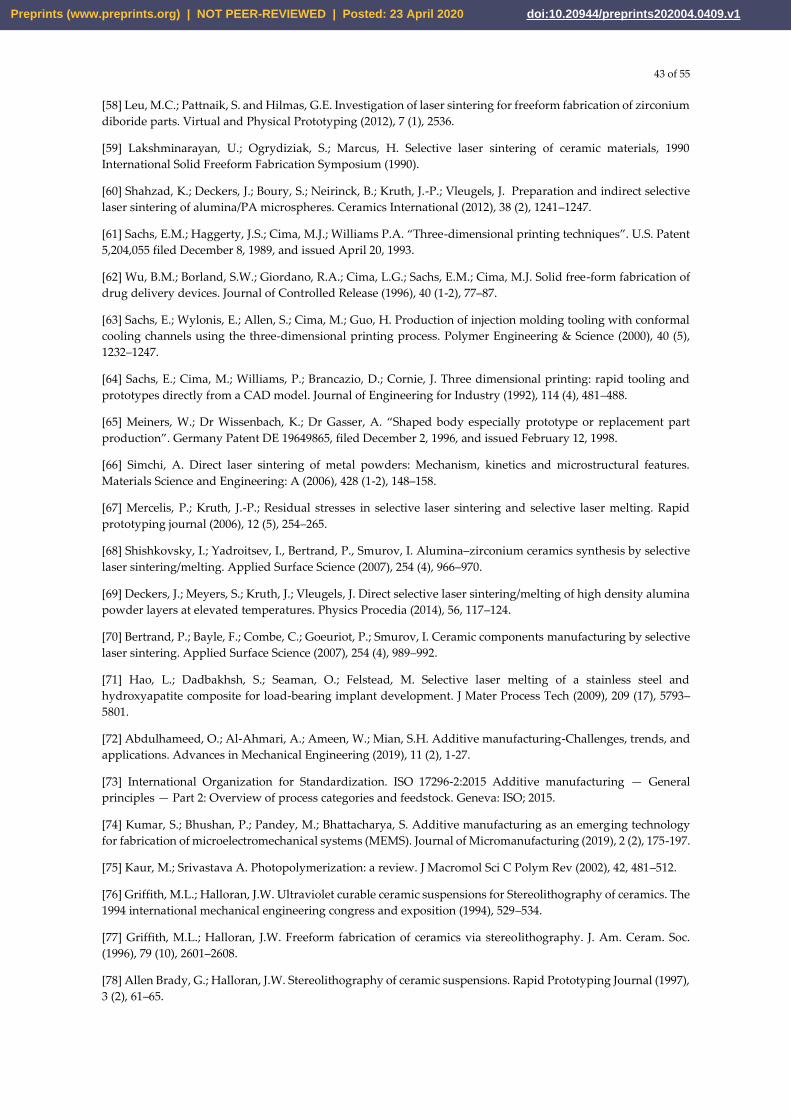
43 of 55
[58] Leu, M.C.; Pattnaik, S. and Hilmas, G.E. Investigation of laser sintering for freeform fabrication of zirconium
diboride parts. Virtual and Physical Prototyping (2012), 7 (1), 2536.
[59] Lakshminarayan, U.; Ogrydiziak, S.; Marcus, H. Selective laser sintering of ceramic materials, 1990
International Solid Freeform Fabrication Symposium (1990).
[60] Shahzad, K.; Deckers, J.; Boury, S.; Neirinck, B.; Kruth, J.-P.; Vleugels, J. Preparation and indirect selective
laser sintering of alumina/PA microspheres. Ceramics International (2012), 38 (2), 1241–1247.
[61] Sachs, E.M.; Haggerty, J.S.; Cima, M.J.; Williams P.A. “Three-dimensional printing techniques”. U.S. Patent
5,204,055 filed December 8, 1989, and issued April 20, 1993.
[62] Wu, B.M.; Borland, S.W.; Giordano, R.A.; Cima, L.G.; Sachs, E.M.; Cima, M.J. Solid free-form fabrication of
drug delivery devices. Journal of Controlled Release (1996), 40 (1-2), 77–87.
[63] Sachs, E.; Wylonis, E.; Allen, S.; Cima, M.; Guo, H. Production of injection molding tooling with conformal
cooling channels using the three-dimensional printing process. Polymer Engineering & Science (2000), 40 (5),
1232–1247.
[64] Sachs, E.; Cima, M.; Williams, P.; Brancazio, D.; Cornie, J. Three dimensional printing: rapid tooling and
prototypes directly from a CAD model. Journal of Engineering for Industry (1992), 114 (4), 481–488.
[65] Meiners, W.; Dr Wissenbach, K.; Dr Gasser, A. “Shaped body especially prototype or replacement part
production”. Germany Patent DE 19649865, filed December 2, 1996, and issued February 12, 1998.
[66] Simchi, A. Direct laser sintering of metal powders: Mechanism, kinetics and microstructural features.
Materials Science and Engineering: A (2006), 428 (1-2), 148–158.
[67] Mercelis, P.; Kruth, J.-P.; Residual stresses in selective laser sintering and selective laser melting. Rapid
prototyping journal (2006), 12 (5), 254–265.
[68] Shishkovsky, I.; Yadroitsev, I., Bertrand, P., Smurov, I. Alumina–zirconium ceramics synthesis by selective
laser sintering/melting. Applied Surface Science (2007), 254 (4), 966–970.
[69] Deckers, J.; Meyers, S.; Kruth, J.; Vleugels, J. Direct selective laser sintering/melting of high density alumina
powder layers at elevated temperatures. Physics Procedia (2014), 56, 117–124.
[70] Bertrand, P.; Bayle, F.; Combe, C.; Goeuriot, P.; Smurov, I. Ceramic components manufacturing by selective
laser sintering. Applied Surface Science (2007), 254 (4), 989–992.
[71] Hao, L.; Dadbakhsh, S.; Seaman, O.; Felstead, M. Selective laser melting of a stainless steel and
hydroxyapatite composite for load-bearing implant development. J Mater Process Tech (2009), 209 (17), 5793–
5801.
[72] Abdulhameed, O.; Al-Ahmari, A.; Ameen, W.; Mian, S.H. Additive manufacturing-Challenges, trends, and
applications. Advances in Mechanical Engineering (2019), 11 (2), 1-27.
[73] International Organization for Standardization. ISO 17296-2:2015 Additive manufacturing — General
principles — Part 2: Overview of process categories and feedstock. Geneva: ISO; 2015.
[74] Kumar, S.; Bhushan, P.; Pandey, M.; Bhattacharya, S. Additive manufacturing as an emerging technology
for fabrication of microelectromechanical systems (MEMS). Journal of Micromanufacturing (2019), 2 (2), 175-197.
[75] Kaur, M.; Srivastava A. Photopolymerization: a review. J Macromol Sci C Polym Rev (2002), 42, 481–512.
[76] Griffith, M.L.; Halloran, J.W. Ultraviolet curable ceramic suspensions for Stereolithography of ceramics. The
1994 international mechanical engineering congress and exposition (1994), 529–534.
[77] Griffith, M.L.; Halloran, J.W. Freeform fabrication of ceramics via stereolithography. J. Am. Ceram. Soc.
(1996), 79 (10), 2601–2608.
[78] Allen Brady, G.; Halloran, J.W. Stereolithography of ceramic suspensions. Rapid Prototyping Journal (1997),
3 (2), 61–65.
Preprints (www.preprints.org) | NOT PEER-REVIEWED | Posted: 23 April 2020 doi:10.20944/preprints202004.0409.v1
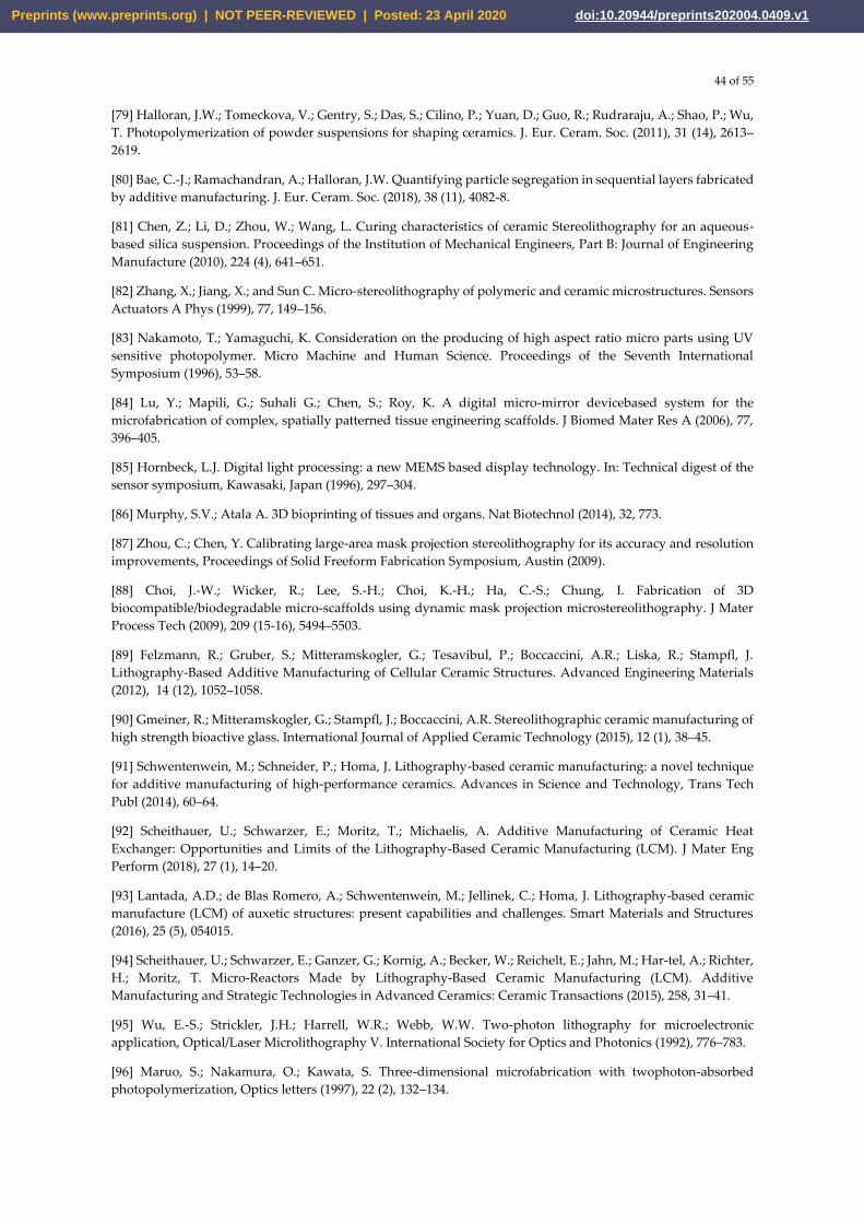
44 of 55
[79] Halloran, J.W.; Tomeckova, V.; Gentry, S.; Das, S.; Cilino, P.; Yuan, D.; Guo, R.; Rudraraju, A.; Shao, P.; Wu,
T. Photopolymerization of powder suspensions for shaping ceramics. J. Eur. Ceram. Soc. (2011), 31 (14), 2613–
2619.
[80] Bae, C.-J.; Ramachandran, A.; Halloran, J.W. Quantifying particle segregation in sequential layers fabricated
by additive manufacturing. J. Eur. Ceram. Soc. (2018), 38 (11), 4082-8.
[81] Chen, Z.; Li, D.; Zhou, W.; Wang, L. Curing characteristics of ceramic Stereolithography for an aqueous-
based silica suspension. Proceedings of the Institution of Mechanical Engineers, Part B: Journal of Engineering
Manufacture (2010), 224 (4), 641–651.
[82] Zhang, X.; Jiang, X.; and Sun C. Micro-stereolithography of polymeric and ceramic microstructures. Sensors
Actuators A Phys (1999), 77, 149–156.
[83] Nakamoto, T.; Yamaguchi, K. Consideration on the producing of high aspect ratio micro parts using UV
sensitive photopolymer. Micro Machine and Human Science. Proceedings of the Seventh International
Symposium (1996), 53–58.
[84] Lu, Y.; Mapili, G.; Suhali G.; Chen, S.; Roy, K. A digital micro-mirror devicebased system for the
microfabrication of complex, spatially patterned tissue engineering scaffolds. J Biomed Mater Res A (2006), 77,
396–405.
[85] Hornbeck, L.J. Digital light processing: a new MEMS based display technology. In: Technical digest of the
sensor symposium, Kawasaki, Japan (1996), 297–304.
[86] Murphy, S.V.; Atala A. 3D bioprinting of tissues and organs. Nat Biotechnol (2014), 32, 773.
[87] Zhou, C.; Chen, Y. Calibrating large-area mask projection stereolithography for its accuracy and resolution
improvements, Proceedings of Solid Freeform Fabrication Symposium, Austin (2009).
[88] Choi, J.-W.; Wicker, R.; Lee, S.-H.; Choi, K.-H.; Ha, C.-S.; Chung, I. Fabrication of 3D
biocompatible/biodegradable micro-scaffolds using dynamic mask projection microstereolithography. J Mater
Process Tech (2009), 209 (15-16), 5494–5503.
[89] Felzmann, R.; Gruber, S.; Mitteramskogler, G.; Tesavibul, P.; Boccaccini, A.R.; Liska, R.; Stampfl, J.
Lithography‐Based Additive Manufacturing of Cellular Ceramic Structures. Advanced Engineering Materials
(2012), 14 (12), 1052–1058.
[90] Gmeiner, R.; Mitteramskogler, G.; Stampfl, J.; Boccaccini, A.R. Stereolithographic ceramic manufacturing of
high strength bioactive glass. International Journal of Applied Ceramic Technology (2015), 12 (1), 38–45.
[91] Schwentenwein, M.; Schneider, P.; Homa, J. Lithography-based ceramic manufacturing: a novel technique
for additive manufacturing of high-performance ceramics. Advances in Science and Technology, Trans Tech
Publ (2014), 60–64.
[92] Scheithauer, U.; Schwarzer, E.; Moritz, T.; Michaelis, A. Additive Manufacturing of Ceramic Heat
Exchanger: Opportunities and Limits of the Lithography-Based Ceramic Manufacturing (LCM). J Mater Eng
Perform (2018), 27 (1), 14–20.
[93] Lantada, A.D.; de Blas Romero, A.; Schwentenwein, M.; Jellinek, C.; Homa, J. Lithography-based ceramic
manufacture (LCM) of auxetic structures: present capabilities and challenges. Smart Materials and Structures
(2016), 25 (5), 054015.
[94] Scheithauer, U.; Schwarzer, E.; Ganzer, G.; Kornig, A.; Becker, W.; Reichelt, E.; Jahn, M.; Har‐tel, A.; Richter,
H.; Moritz, T. Micro‐Reactors Made by Lithography‐Based Ceramic Manufacturing (LCM). Additive
Manufacturing and Strategic Technologies in Advanced Ceramics: Ceramic Transactions (2015), 258, 31–41.
[95] Wu, E.-S.; Strickler, J.H.; Harrell, W.R.; Webb, W.W. Two-photon lithography for microelectronic
application, Optical/Laser Microlithography V. International Society for Optics and Photonics (1992), 776–783.
[96] Maruo, S.; Nakamura, O.; Kawata, S. Three-dimensional microfabrication with twophoton-absorbed
photopolymerization, Optics letters (1997), 22 (2), 132–134.
Preprints (www.preprints.org) | NOT PEER-REVIEWED | Posted: 23 April 2020 doi:10.20944/preprints202004.0409.v1
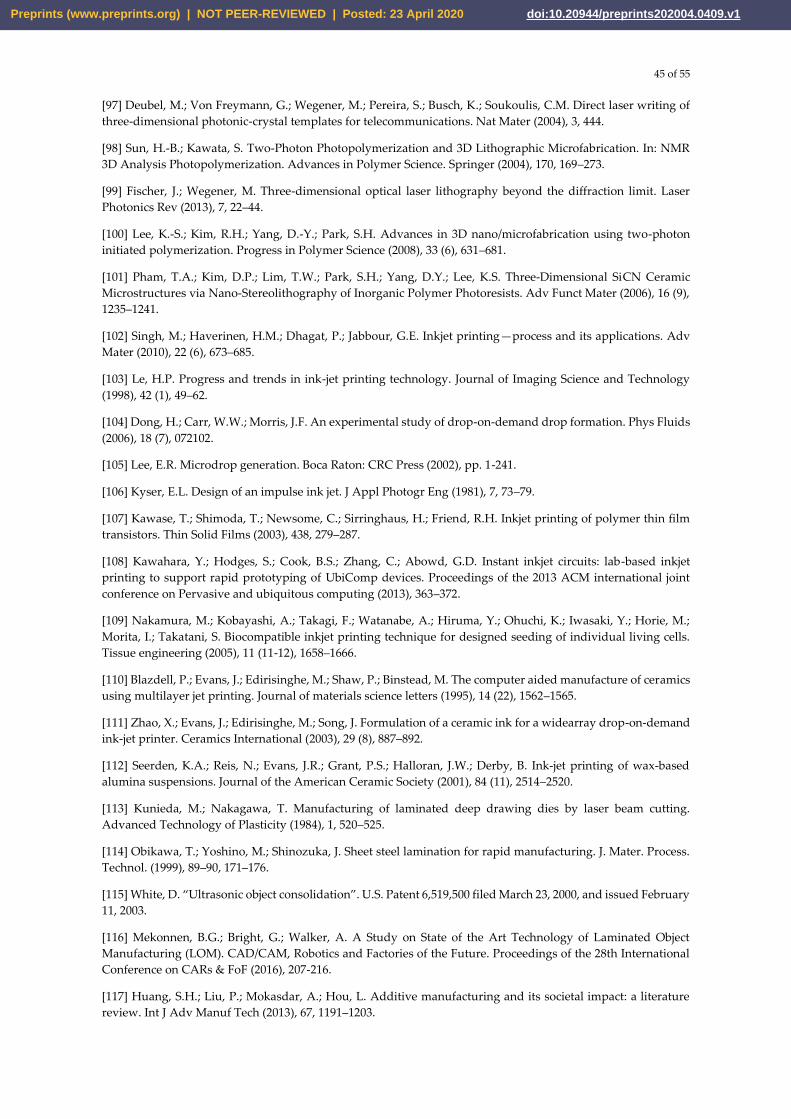
45 of 55
[97] Deubel, M.; Von Freymann, G.; Wegener, M.; Pereira, S.; Busch, K.; Soukoulis, C.M. Direct laser writing of three-dimensional photonic-crystal templates for telecommunications. Nat Mater (2004), 3, 444.
[98] Sun, H.-B.; Kawata, S. Two-Photon Photopolymerization and 3D Lithographic Microfabrication. In: NMR 3D Analysis Photopolymerization. Advances in Polymer Science. Springer (2004), 170, 169–273.
[99] Fischer, J.; Wegener, M. Three-dimensional optical laser lithography beyond the diffraction limit. Laser Photonics Rev (2013), 7, 22–44.
[100] Lee, K.-S.; Kim, R.H.; Yang, D.-Y.; Park, S.H. Advances in 3D nano/microfabrication using two-photon initiated polymerization. Progress in Polymer Science (2008), 33 (6), 631–681.
[101] Pham, T.A.; Kim, D.P.; Lim, T.W.; Park, S.H.; Yang, D.Y.; Lee, K.S. Three‐Dimensional SiCN Ceramic Microstructures via Nano‐Stereolithography of Inorganic Polymer Photoresists. Adv Funct Mater (2006), 16 (9), 1235–1241.
[102] Singh, M.; Haverinen, H.M.; Dhagat, P.; Jabbour, G.E. Inkjet printing—process and its applications. Adv Mater (2010), 22 (6), 673–685.
[103] Le, H.P. Progress and trends in ink-jet printing technology. Journal of Imaging Science and Technology (1998), 42 (1), 49–62.
[104] Dong, H.; Carr, W.W.; Morris, J.F. An experimental study of drop-on-demand drop formation. Phys Fluids (2006), 18 (7), 072102.
[105] Lee, E.R. Microdrop generation. Boca Raton: CRC Press (2002), pp. 1-241.
[106] Kyser, E.L. Design of an impulse ink jet. J Appl Photogr Eng (1981), 7, 73–79.
[107] Kawase, T.; Shimoda, T.; Newsome, C.; Sirringhaus, H.; Friend, R.H. Inkjet printing of polymer thin film transistors. Thin Solid Films (2003), 438, 279–287.
[108] Kawahara, Y.; Hodges, S.; Cook, B.S.; Zhang, C.; Abowd, G.D. Instant inkjet circuits: lab-based inkjet printing to support rapid prototyping of UbiComp devices. Proceedings of the 2013 ACM international joint conference on Pervasive and ubiquitous computing (2013), 363–372.
[109] Nakamura, M.; Kobayashi, A.; Takagi, F.; Watanabe, A.; Hiruma, Y.; Ohuchi, K.; Iwasaki, Y.; Horie, M.; Morita, I.; Takatani, S. Biocompatible inkjet printing technique for designed seeding of individual living cells. Tissue engineering (2005), 11 (11-12), 1658–1666.
[110] Blazdell, P.; Evans, J.; Edirisinghe, M.; Shaw, P.; Binstead, M. The computer aided manufacture of ceramics using multilayer jet printing. Journal of materials science letters (1995), 14 (22), 1562–1565.
[111] Zhao, X.; Evans, J.; Edirisinghe, M.; Song, J. Formulation of a ceramic ink for a widearray drop-on-demand ink-jet printer. Ceramics International (2003), 29 (8), 887–892.
[112] Seerden, K.A.; Reis, N.; Evans, J.R.; Grant, P.S.; Halloran, J.W.; Derby, B. Ink‐jet printing of wax‐based alumina suspensions. Journal of the American Ceramic Society (2001), 84 (11), 2514–2520.
[113] Kunieda, M.; Nakagawa, T. Manufacturing of laminated deep drawing dies by laser beam cutting. Advanced Technology of Plasticity (1984), 1, 520–525.
[114] Obikawa, T.; Yoshino, M.; Shinozuka, J. Sheet steel lamination for rapid manufacturing. J. Mater. Process. Technol. (1999), 89–90, 171–176.
[115] White, D. “Ultrasonic object consolidation”. U.S. Patent 6,519,500 filed March 23, 2000, and issued February 11, 2003.
[116] Mekonnen, B.G.; Bright, G.; Walker, A. A Study on State of the Art Technology of Laminated Object Manufacturing (LOM). CAD/CAM, Robotics and Factories of the Future. Proceedings of the 28th International Conference on CARs & FoF (2016), 207-216.
[117] Huang, S.H.; Liu, P.; Mokasdar, A.; Hou, L. Additive manufacturing and its societal impact: a literature review. Int J Adv Manuf Tech (2013), 67, 1191–1203.
Preprints (www.preprints.org) | NOT PEER-REVIEWED | Posted: 23 April 2020 doi:10.20944/preprints202004.0409.v1
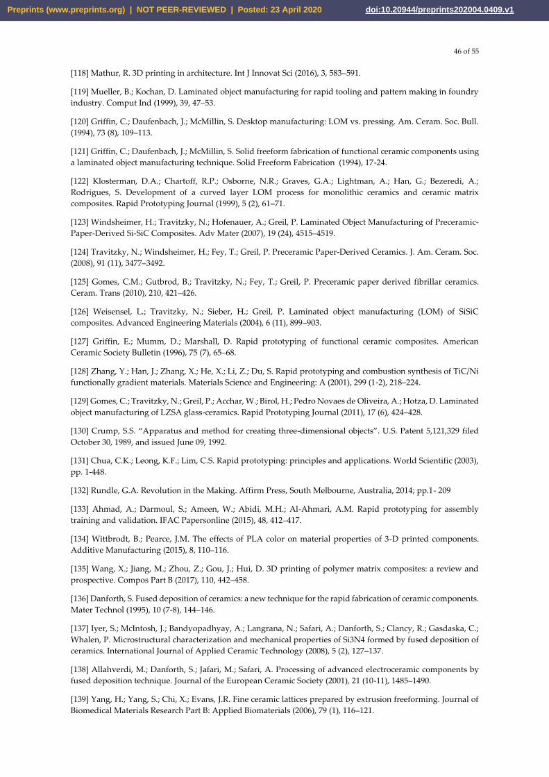
46 of 55
[118] Mathur, R. 3D printing in architecture. Int J Innovat Sci (2016), 3, 583–591.
[119] Mueller, B.; Kochan, D. Laminated object manufacturing for rapid tooling and pattern making in foundry
industry. Comput Ind (1999), 39, 47–53.
[120] Griffin, C.; Daufenbach, J.; McMillin, S. Desktop manufacturing: LOM vs. pressing. Am. Ceram. Soc. Bull.
(1994), 73 (8), 109–113.
[121] Griffin, C.; Daufenbach, J.; McMillin, S. Solid freeform fabrication of functional ceramic components using
a laminated object manufacturing technique. Solid Freeform Fabrication (1994), 17-24.
[122] Klosterman, D.A.; Chartoff, R.P.; Osborne, N.R.; Graves, G.A.; Lightman, A.; Han, G.; Bezeredi, A.;
Rodrigues, S. Development of a curved layer LOM process for monolithic ceramics and ceramic matrix
composites. Rapid Prototyping Journal (1999), 5 (2), 61–71.
[123] Windsheimer, H.; Travitzky, N.; Hofenauer, A.; Greil, P. Laminated Object Manufacturing of Preceramic‐
Paper‐Derived Si-SiC Composites. Adv Mater (2007), 19 (24), 4515–4519.
[124] Travitzky, N.; Windsheimer, H.; Fey, T.; Greil, P. Preceramic Paper‐Derived Ceramics. J. Am. Ceram. Soc.
(2008), 91 (11), 3477–3492.
[125] Gomes, C.M.; Gutbrod, B.; Travitzky, N.; Fey, T.; Greil, P. Preceramic paper derived fibrillar ceramics.
Ceram. Trans (2010), 210, 421–426.
[126] Weisensel, L.; Travitzky, N.; Sieber, H.; Greil, P. Laminated object manufacturing (LOM) of SiSiC
composites. Advanced Engineering Materials (2004), 6 (11), 899–903.
[127] Griffin, E.; Mumm, D.; Marshall, D. Rapid prototyping of functional ceramic composites. American
Ceramic Society Bulletin (1996), 75 (7), 65–68.
[128] Zhang, Y.; Han, J.; Zhang, X.; He, X.; Li, Z.; Du, S. Rapid prototyping and combustion synthesis of TiC/Ni
functionally gradient materials. Materials Science and Engineering: A (2001), 299 (1-2), 218–224.
[129] Gomes, C.; Travitzky, N.; Greil, P.; Acchar, W.; Birol, H.; Pedro Novaes de Oliveira, A.; Hotza, D. Laminated
object manufacturing of LZSA glass-ceramics. Rapid Prototyping Journal (2011), 17 (6), 424–428.
[130] Crump, S.S. “Apparatus and method for creating three-dimensional objects”. U.S. Patent 5,121,329 filed
October 30, 1989, and issued June 09, 1992.
[131] Chua, C.K.; Leong, K.F.; Lim, C.S. Rapid prototyping: principles and applications. World Scientific (2003),
pp. 1-448.
[132] Rundle, G.A. Revolution in the Making. Affirm Press, South Melbourne, Australia, 2014; pp.1- 209
[133] Ahmad, A.; Darmoul, S.; Ameen, W.; Abidi, M.H.; Al-Ahmari, A.M. Rapid prototyping for assembly
training and validation. IFAC Papersonline (2015), 48, 412–417.
[134] Wittbrodt, B.; Pearce, J.M. The effects of PLA color on material properties of 3-D printed components.
Additive Manufacturing (2015), 8, 110–116.
[135] Wang, X.; Jiang, M.; Zhou, Z.; Gou, J.; Hui, D. 3D printing of polymer matrix composites: a review and
prospective. Compos Part B (2017), 110, 442–458.
[136] Danforth, S. Fused deposition of ceramics: a new technique for the rapid fabrication of ceramic components.
Mater Technol (1995), 10 (7-8), 144–146.
[137] Iyer, S.; McIntosh, J.; Bandyopadhyay, A.; Langrana, N.; Safari, A.; Danforth, S.; Clancy, R.; Gasdaska, C.;
Whalen, P. Microstructural characterization and mechanical properties of Si3N4 formed by fused deposition of
ceramics. International Journal of Applied Ceramic Technology (2008), 5 (2), 127–137.
[138] Allahverdi, M.; Danforth, S.; Jafari, M.; Safari, A. Processing of advanced electroceramic components by
fused deposition technique. Journal of the European Ceramic Society (2001), 21 (10-11), 1485–1490.
[139] Yang, H.; Yang, S.; Chi, X.; Evans, J.R. Fine ceramic lattices prepared by extrusion freeforming. Journal of
Biomedical Materials Research Part B: Applied Biomaterials (2006), 79 (1), 116–121.
Preprints (www.preprints.org) | NOT PEER-REVIEWED | Posted: 23 April 2020 doi:10.20944/preprints202004.0409.v1
47 of 55
[140] Jafari, M.; Han, W.; Mohammadi, F.; Safari, A.; Danforth, S.; Langrana, N. A novel system for fused
deposition of advanced multiple ceramics. Rapid Prototyping Journal (2000), 6 (3), 161–175.
[141] Hutmacher, D.W.; Schantz, T.; Zein, I.; Ng, K.W.; Teoh, S.H.; Tan, K.C. Mechanical properties and cell
cultural response of polycaprolactone scaffolds designed and fabricated via fused deposition modeling. Journal
of Biomedical Materials Research (2001), 55 (2), 203–216.
[142] Cao, T.; Ho, K.-H.; Teoh, S.-H. Scaffold design and in vitro study of osteochondral coculture in a three-
dimensional porous polycaprolactone scaffold fabricated by fused deposition modeling. Tissue engineering
(2003), 9 (4), 103–112.
[143] Tsang, V.L.; Bhatia, S.N. Three-dimensional tissue fabrication. Advanced drug delivery reviews (2004), 56
(11), 1635–1647.
[144] Xu, N.; Ye, X.; Wei, D.; Zhong, J.; Chen, Y.; Xu, G.; He, D. 3D artificial bones for bone repair prepared by
computed tomography-guided fused deposition modeling for bone repair. ACS applied materials & interfaces
(2014), 6 (17), 14952–14963.
[145] Sa, M.W.; Nguyen, B.N.B.; Moriarty, R.A.; Kamalitdinov, T.; Fisher, J.P.; Kim, J.Y. Fabrication and
evaluation of 3D printed BCP scaffolds reinforced with ZrO2 for bone tissue applications. Biotechnology and
bioengineering (2018), 115 (4), 989–999.
[146] Pilleux, M.E.; Safari, A.; Allahverdi, M.; Chen, Y.; Lu, Y.; Jafari, M.A. 3-D photonic bandgap structures in
the microwave regime by fused deposition of multimaterials. Rapid Prototyping Journal (2002), 8 (1), 46–52.
[147] Chen, Y.; Bartzos, D.; Lu, Y.; Niver, E.; Pilleux, M.; Allahverdi, M.; Danforth, S.; Safari, A. Simulation,
fabrication, and characterization of 3‐D alumina photonic bandgap structures. Microwave and Optical
Technology Letters (2001), 30 (5), 305–307.
[148] Cesarano, I.; Segalman, R. Robocasting provides moldless fabrication from slurry deposition. Ceramic
Industry (1998), 148 (4), 94–100.
[149] Shen, A.; Caldwell, D.; Ma, A.W.K.; Dardona, S. Direct write fabrication of high-density parallel silver
interconnects. Additive Manufacturing (2018), 22, 343-350.
[150] Hartmann, K.; Krishnan, R.; Merz, R.; Neplotnik, G.; Prinz, F.B.; Schultz, L.; Terk, M.; Weiss, L.E. Robot-
assisted shape deposition manufacturing. Proceedings of the 1994 IEEE International Conference on Robotics
and Automation, San Diego, CA, USA (1994), 4, 2890-2895.
[151] Cesarano III, J.; Calvert, P.D. “Freeforming objects with low-binder slurry” U.S. Patent 6,027,326, filed
October 28, 1997, and issued February 22, 2000.
[152] Cesarano, J. Robocasting: direct fabrication of ceramics from colloidal suspensions. Proc. Solid Free. Fabr.
Symp., Austin, TX (1997), 25–36.
[153] Fu, K.; Wang, Y.; Yan, C.; Yao, Y.; Chen, Y.; Dai, J.; Lacey, S.; Wang, Y.; Wan, J.; Li, T.; Wang, Z.; Xu, Y.; Hu,
L. Graphene oxide-based electrode inks for 3D-printed lithium-ion batteries. Adv Mater (2016), 28, 2587–2594.
[154] Farahani, R.D.; Dubé, M.; Therriault, D. Three-dimensional printing of multifunctional nanocomposites:
manufacturing techniques and applications. Adv Mater (2016), 28, 5794–5821.
[155] Zhu, C.; Liu, T.; Qian, F.; Han, T.Y.-J.; Duoss, E.B.; Kuntz, J.D.; Spadaccini, C.M.; Worsley, M.A.l Li, Y.
Supercapacitors based on three-dimensional hierarchical graphene aerogels with periodic macropores. Nano
Lett (2016), 16, 3448–3456.
[156] Zhang, F.; Wei, M.; Viswanathan, V.V.; Swart, B.; Shao, Y.; Wu, G.; Zhou, C. 3D printing technologies for
electrochemical energy storage. Nano Energy (2017), 40, 418–431.
[157] Elsayed, H.; Colombo, P.; Bernardo, E. Direct ink writing of wollastonite-diopside glass-ceramic scaffolds
from a silicone resin and engineered fillers. Journal of the European Ceramic Society (2017), 37 (13), 4187–4195.
[158] Feilden, E.; Blanca, E.G.-T.; Giuliani, F.; Saiz, E.; Vandeperre, L. Robocasting of structural ceramic parts
with hydrogel inks. Journal of the European Ceramic Society (2016), 36 (10), 2525–2533.
Preprints (www.preprints.org) | NOT PEER-REVIEWED | Posted: 23 April 2020 doi:10.20944/preprints202004.0409.v1
48 of 55
[159] Rao, R.B.; Krafcik, K.L.; Morales, A.M.; Lewis, J.A. Microfabricated deposition nozzles for direct‐write
assembly of three‐dimensional periodic structures. Adv Mater (2005), 17 (3), 289–293.
[160] Schlordt, T.; Schwanke, S.; Keppner, F.; Fey, T.; Travitzky, N.; Greil, P. Robocasting of alumina hollow
filament lattice structures. Journal of the European Ceramic Society (2013), 33 (15-16), 3243–3248.
[161] Smay, J.E.; Cesarano, J.; Lewis, J.A. Colloidal inks for directed assembly of 3-D periodic structures.
Langmuir (2002), 18 (14), 5429–5437.
[162] Sun, K.; Wei, T.S.; Ahn, B.Y.; Seo, J.Y.; Dillon, S.J.; Lewis, J.A. 3D printing of interdigitated Li‐Ion
microbattery architectures. Adv Mater (2013), 25 (33), 4539–4543.
[163] Liu, C.; Cheng, X.; Li, B.; Chen, Z.; Mi, S.; Lao, C. Fabrication and Characterization of 3D-Printed Highly-
Porous 3D LiFePO4 Electrodes by Low Temperature Direct Writing Process. Materials (2017), 10 (8), 934.
[164] Miranda, P.; Saiz, E.; Gryn, K.; Tomsia, A.P. Sintering and robocasting of β-tricalcium phosphate scaffolds
for orthopaedic applications. Acta biomaterialia (2006), 2 (4), 457–466.
[165] Eqtesadi, S.; Motealleh, A.; Miranda, P.; Lemos, A.; Rebelo, A.; Ferreira, J.M. A simple recipe for direct
writing complex 45S5 Bioglass® 3D scaffolds. Materials Letters (2013), 93, 68–71.
[166] Simon, J.L.; Michna, S.; Lewis, J.A.; Rekow, E.D.; Thompson, V.P.; Smay, J.E.; Yampolsky, A.; Parsons, J.R.;
Ricci, J.L. In vivo bone response to 3D periodic hydroxyapatite scaffolds assembled by direct ink writing. Journal
of Biomedical Materials Research Part A (2007), 83 (3), 747–758.
[167] Dellinger, J.G. Development of model hydroxyapatite bone scaffolds with multiscale porosity for potential
load bearing applications. Doctoral thesis, University of Illinois at Urbana-Champaign, Illinois, USA, 2005.
[168] Dellinger, J.G.; Eurell, J.A.C.; Jamison, R.D. Bone response to 3D periodic hydroxyapatite scaffolds with
and without tailored microporosity to deliver bone morphogenetic protein 2. Journal of Biomedical Materials
Research Part A (2006), 76 (2), 366–376.
[169] Miranda, P.; Pajares, A.; Saiz, E.; Tomsia, A.P.; Guiberteau, F. Mechanical properties of calcium phosphate
scaffolds fabricated by robocasting. Journal of Biomedical Materials Research Part A (2008), 85 (1), 218–227.
[170] Poole C.P.Jr.; Owens F.J. Introduction to Nanotechnology. A John Wiley & Sons (2003), pp. 1-371.
[171] Grigoriev, S; Peretyagin, P.; Smirnov, A; Solis, W; Díaz, L.A.; Fernández, A. Effect of graphene addition on
the mechanical and electrical properties of Al2O3-SiCw ceramics. J. Eur. Ceram. Soc. (2017), 37(6), 2473-2479
[172] Smirnov, A; Peretyagin, P.; Solis Pinargote, N.W.; Gerchman, I; Bartolomé, J.F. Wear behavior of graphene-
reinforced alumina–silicon carbide whisker nanocomposite. Nanomaterials (2019), 9 (2), 151
[173] Solis Pinargote, N. W.; Peretyagin, P.; Seleznev, A.; Torrecillas, R.; Moya, J. S. Black zirconia-graphene
nanocomposite produced by spark plasma sintering. AIP Conference Proceedings, (2016), 1785 (1), 040074.
[174] Fokin, P. V.; Solis Pinargote, N. W.; Kuznetsova, E. V.; Peretyagin, P. Y.; Smirnov, A. Effect of Drying
Methods of Alumina Powder and Graphene Oxide Mixture on the Mechanical and Electrical Properties of
Sintered Composites Fabricated by Spark Plasma Sintering. Inorg. Mater. Appl. Res. (2018), 9, 930–936
[175] Markandan, K.; Chin, J. K.; Tan, M. T. T. Recent progress in graphene based ceramic composites: a review.
Journal of Materials Research (2016), 32(01), 84–106.
[176] Nieto, A.; Bisht, A.; Lahiri, D.; Zhang, C.; Agarwal, A. Graphene reinforced metal and ceramic matrix
composites: a review. International Materials Reviews (2016), 62(5), 241–302.
[177] Novoselov, K.S.; Fal′ko, V.I.; Colombo, L.; Gellert, P.R.; Schwab, M.G.; Kim, K. A roadmap for graphene.
Nature (2012), 490, 192–200.
[178] Balandin, A.A.; Ghosh, S.; Bao, W.; Calizo, I.; Teweldebrhan, D.; Miao, F.; Lau, C.N. Superior thermal
conductivity of single-layer graphene. Nano Lett (2008), 8 (3), 902–907.
[179] Balandin, A.A. Thermal properties of graphene and nanostructured carbon materials. Nat Mater (2011), 10,
569–581.
Preprints (www.preprints.org) | NOT PEER-REVIEWED | Posted: 23 April 2020 doi:10.20944/preprints202004.0409.v1
49 of 55
[180] Lee, C.; Wei, X.D.; Kysar, J.W.; Hone, J. Measurement of the elastic properties and intrinsic strength of
monolayer graphene. Science (2008), 321(5887), 385–388.
[181] Zhu, Y.; Murali, S.; Cai, W.; Li, X.; Suk, J.W.; Potts, J.R.; Ruoff, R.S. Graphene and graphene oxide: synthesis,
properties, and applications. Adv Mater (2010), 22 (35), 3906–3924.
[182] Novoselov, K.; Geim, A.K.; Morozov, S.; Jiang, D.; Katsnelson, M.; Grigorieva, I.; Dubonos, S.V.; Firsov,
A.A. Two-dimensional gas of massless Dirac fermions in graphene. Nature (2005), 438(7065), 197–200.
[183] Nair, R.R.; Blake, P.; Grigorenko, A.N.; Novoselov, K.S.; Booth, T.J.; Stauber, T.; Peres, N.M.R.; Geim, A.K.
Fine structure constant defines visual transparency of graphene. Science (2008), 320, 1308–1308.
[184] Jo, G.; Choe, M.; Lee, S.; Park, W.; Kahng, Y.H.; Lee, T. The application of graphene as electrodes in electrical
and optical devices. Nanotechnology (2012), 23 (11),1-19.
[185] Bunch, J.S.; Verbridge, S.S.; Alden, J.S.; van der Zande, A.M.; Parpia, J.M.; Craighead, H.G.; Mc Euen, P.L.
Impermeable atomic membranes from graphene sheets. Nano Lett (2008), 8, 2458–2462.
[186] Nayak, T.R.; Andersen, H.; Makam, V.S.; Khaw, C.; Bae, S.; Xu, X.; Ee, P.-L.R.; Ahn, J.-H.; Hong, B.H.;
Pastorin, G.; Özyilmaz, B. Graphene for Controlled and Accelerated Osteogenic Differentiation of Human
Mesenchymal Stem Cells. ACS Nano (2011), 5 (6), 4670–4678.
[187] Potts, J.R.; Dreyer, D.R.; Bielawski, C.W.; Ruoff, R.S. Graphene-based polymer nanocomposites. Polymer
(2011), 52(1), 5–25.
[188] Papageorgiou, D.G.; Kinloch, I.A.; Young, R.J. Graphene/elastomer nanocomposites. Carbon (2015), 95,
460–484.
[189] Eda, G.; Chhowalla, M. Chemically derived graphene oxide: towards large-area thin-film electronics and
optoelectronics. Adv Mater (2010), 22 (22), 2392–2415.
[190] Wang, J.; Xu, Y.; Chen, H.; Zhang, B. Ultraviolet dielectric hyperlens with layered graphene and boron
nitride. Journal of Materials Chemistry (2012), 22 (31), 15863.
[191] Yoo, J.J.; Balakrishnan, K.; Huang, J.; Meunier, V.; Sumpter, B.G.; Srivastava, A.; Conway, M.; Reddy,
A.L.M.; Yu, J.; Vajtai, R.; Ajayan, P.M. Ultrathin planar graphene supercapacitors. Nano Lett (2011), 11(4), 1423–
1427.
[192] Patchkovskii, S.; John, S.T.; Yurchenko, S.N.; Zhechkov, L.; Heine, T.; Seifert, G. Graphene nanostructures
as tunable storage media for molecular hydrogen. Proc Natl Acad Sci USA (2005), 102(30), 10439–10444.
[193] Schwierz, F. Graphene transistors. Nat Nanotechnol (2010), 5(7), 487–96.
[194] Bunch, J.S.; Van Der Zande, A.M.; Verbridge, S.S.; Frank, I.W.; Tanenbaum, D.M.; Parpia, J.M.; Craighead,
H.G.; McEuen, P.L. Electromechanical resonators from graphene sheets. Science (2007), 315(5811), 490–493.
[195] Reina, A.; Jia, X.; Ho, J.; Nezich, D.; Son, H.; Bulovic, V.; Dresselhaus, M.S.; Kong, J. Large area, few-layer
graphene films on arbitrary substrates by chemical vapor deposition. Nano Lett (2009), 9, 30–35.
[196] Hu, B.; Ago, H.; Ito, Y.; Kawahara, K.; Tsuji, M.; Magome, E.; Sumitani, K.; Mizuta, N.; Ikeda, K.; Mizuno,
S. Epitaxial growth of large-area single-layer graphene over Cu(111)/sapphire by atmospheric pressure CVD.
Carbon (2012), 50, 57–65.
[197] Stankovich, S.; Dikin, D.A.; Piner, R.D.; Kohlhaas, K.A.; Kleinhammes, A.; Jia Y.; Wu, Y.; Nguyen, S.T.;
Ruoff, R.S. Synthesis of graphene-based nanosheets via chemical reduction of exfoliated graphite oxide. Carbon
(2007), 45, 1558–1565.
[198] Novoselov, K.S.; Geim, A.K.; Morozov, S.V.; Jiang, D.; Zhang, Y.; Dubonos, S.V.; Grigorieva, I.V.; Firsov,
A.A. Electric field effect in atomically thin carbon films. Science (2004), 306, 666–669.
[199] Munz, M.; Giusca, C.E.; Myers-Ward, R.L., Gaskill, D.K.; Kazakova, O. Thickness-Dependent
Hydrophobicity of Epitaxial Graphene. ACS Nano (2015), 9 (8), 8401-8411.
[200] Liu, J.; Tang, J.; Gooding, J.J. Strategies for chemical modification of graphene and applications of
chemically modified graphene. Journal of Materials Chemistry (2012), 22(25), 12435.
Preprints (www.preprints.org) | NOT PEER-REVIEWED | Posted: 23 April 2020 doi:10.20944/preprints202004.0409.v1
50 of 55
[201] Bagherzadeh, M.; Farahbakhsh, A. Surface Functionalization of Graphene. Graphene Materials (2015), 25–
65.
[202] Sun, X.; Li, B.; Lu, M. A covalent modification for graphene by adamantane groups through two-step
chlorination-Grignard reactions. J Solid State Chem (2017), 251, 194–197.
[203] Qi, X.; Pu, K.Y.; Li, H.; Zhou, X.; Wu, S.; Fan, Q.L.; Liu, B.; Boey, F.; Huang, W.; Zhang, H. Amphiphilic
graphene composites. Angew Chem Int Ed (2010), 49, 9426–9429.
[204] Zaaba, N. I.; Foo, K.L.; Hashim, U.; Tan, S.J.; Liu, W.-W.; Voon, C. H. Synthesis of Graphene Oxide using
Modified Hummers Method: Solvent Influence. Procedia Engineering (2017), 184, 469–477.
[205] Hummers, W.S.; Offeman, R.E. Preparation of graphitic oxide. J Am Chem Soc (1958), 80, 1339–1339.
[206] Singh, V.; Joung, D.; Zhai, L.; Das, S.; Khondaker, S.I.; Seal, S. Graphene based materials: past, present and
future. Prog Mater Sci (2011), 56, 1178–1271.
[207] Stankovich, S.; Piner, R.D.; Chen, X.; Wu, N.; Nguyen, S.T.; Ruoff, R.S. Stable aqueous dispersions of
graphitic nanoplatelets via the reduction of exfoliated graphite oxide in the presence of poly(sodium 4-
styrenesulfonate). J Mater Chem (2006), 16, 155–158.
[208] Becerril, H.A.; Mao, J.; Liu, Z.; Stoltenberg, R.M.; Bao, Z.; Chen, Y. Evaluation of solution-processed reduced
graphene oxide films as transparent conductors. ACS Nano (2008), 2, 463–470.
[209] An, B.W.; Kim, K.; Kim, M.; Kim, S.Y.; Hur, S.H.; Park, J.U. Direct printing of reduced graphene oxide on
planar or highly curved surfaces with high resolutions using electrohydrodynamics. Small (2015), 11, 2263–2268.
[210] Zhang, J.-X.; Liang, Y.-X.; Wang, X.; Zhou, H.-J.; Li, S.-Y.; Zhang, J.; Feng, Y.; Lu, N.; Wang, Q., Guo, Z.
Strengthened epoxy resin with hyperbranched polyamineester anchored graphene oxide via novel phase
transfer approach. Adv Compos Hybrid Mater (2018), 1, 300–309.
[211] Yu, A.; Ramesh, P.; Itkis, M.E.; Bekyarova, E.; Haddon, R.C. Graphite nanoplatelet-epoxy composite
thermal interface materials. J Phys Chem C (2007), 111, 7565–7569.
[212] Syurik, Y.V.; Ghislandi, M.G.; Tkalya, E.E.; Paterson, G.; McGrouther, D.; Ageev, O.A.; Loos, J. Graphene
network organisation in conductive polymer composites. Macromol Chem Phys (2012), 213, 1251– 1258.
[213] Huang, X.; Yin, Z.; Wu, S.; Qi, X.; He, Q.; Zhang, Q.; Yan, Q.; Boey, F.; Zhang, H. Graphene-based materials:
synthesis, characterization, properties, and applications. Small (2011), 7, 1876–1902.
[214] Wu, H.; Huang, X.; Qian, L. Recent progress on the metacompoistes with carbonaceous fillers. Eng Sci
(2018), 2, 17–25.
[215] Zhou, X.; Huang, X.; Qi, X.; Wu, S.; Xue, C.; Boey, F.Y.C.; Yan, Q.; Chen, P.; Zhang, H. In situ synthesis of
metal nanoparticles on single-layer graphene oxide and reduced graphene oxide surfaces. J Phys Chem C (2009),
113, 10842–10846.
[216] Yan, J.; Wei, T.; Qiao, W.; Shao, B.; Zhao, Q.; Zhang, L.; Fan, Z. Rapid microwave-assisted synthesis of
graphene nanosheet/Co3O4 composite for supercapacitors. Electrochim Acta (2010), 55, 6973–6978.
[217] Ahmad, J.; Majid, K. In-situ synthesis of visible-light responsive Ag2O/graphene oxide nanocomposites and
effect of graphene oxide content on its photocatalytic activity. Adv Compos Hybrid Mater (2018), 1, 374–388.
[218] Guo, C.X.; Yang, H.B.; Sheng, Z.M.; Lu, Z.S.; Song, Q.L.; Li, C.M. Layered graphene/quantum dots for
photovoltaic devices. Angew Chem Int Ed (2010), 49, 3014–3017.
[219] Acquah, S.F.A.; Leonhardt, B.E.; Nowotarski, M.S.; Magi, J.M.; Al-Hariri, L.A. Carbon Nanotubes and
Graphene as Additives in 3D Printing. Carbon Nanotubes - Current Progress of their Polymer Composites,
Mohamed Reda Berber and Inas Hazzaa Hafez, IntechOpen (2016).
[220] Compton, O.C.; Kim, S.; Pierre, C.; Torkelson, J.M.; Nguyen, S.T. Crumpled graphene nanosheets as highly
effective barrier property enhancers. Adv. Mater. (2010), 22, 4759–4763.
[221] Kim, H.; Miura, Y.; Macosko, C.W. Graphene/polyurethane nanocomposites for improved gas barrier and
electrical conductivity. Chem. Mater. (2010), 22, 3441–3450.
Preprints (www.preprints.org) | NOT PEER-REVIEWED | Posted: 23 April 2020 doi:10.20944/preprints202004.0409.v1
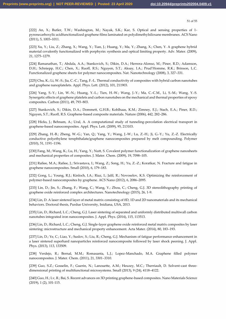
51 of 55
[222] An, X.; Butler, T.W.; Washington, M.; Nayak, S.K.; Kar, S. Optical and sensing properties of 1-
pyrenecarboxylic acidfunctionalized graphene films laminated on polydimethylsiloxane membranes. ACS Nano
(2011), 5, 1003–1011.
[223] Xu, Y.; Liu, Z.; Zhang, X.; Wang, Y.; Tian, J.; Huang, Y.; Ma, Y.; Zhang, X.; Chen, Y. A graphene hybrid
material covalently functionalized with porphyrin: synthesis and optical limiting property. Adv. Mater. (2009),
21, 1275–1279.
[224] Ramanathan, T.; Abdala, A.A.; Stankovich, S.; Dikin, D.A.; Herrera-Alonso, M.; Piner, R.D.; Adamson,
D.H.; Schniepp, H.C.; Chen, X.; Ruoff, R.S.; Nguyen, S.T.; Aksay, I.A.; Prud’Homme, R.K.; Brinson, L.C.
Functionalized graphene sheets for polymer nanocomposites. Nat. Nanotechnology (2008), 3, 327–331.
[225] Chu, K.; Li, W.-S.; Jia, C.-C.; Tang, F.-L. Thermal conductivity of composites with hybrid carbon nanotubes
and graphene nanoplatelets. Appl. Phys. Lett. (2012), 101, 211903.
[226] Yang, S.-Y.; Lin, W.-N.; Huang, Y.-L.; Tien, H.-W.; Wang, J.-Y.; Ma, C.-C.M., Li, S.-M.; Wang, Y.-S.
Synergetic effects of graphene platelets and carbon nanotubes on the mechanical and thermal properties of epoxy
composites. Carbon (2011), 49, 793–803.
[227] Stankovich, S.; Dikin, D.A.; Dommett, G.H.B.; Kohlhaas, K.M.; Zimney, E.J.; Stach, E.A.; Piner, R.D.;
Nguyen, S.T.; Ruoff, R.S. Graphene-based composite materials. Nature (2006), 442, 282–286.
[228] Hicks, J.; Behnam, A.; Ural, A. A computational study of tunneling-percolation electrical transport in
graphene-based nanocomposites. Appl. Phys. Lett. (2009), 95, 213103.
[229] Zhang, H.-B.; Zheng, W.-G.; Yan, Q.; Yang, Y.; Wang, J.-W.; Lu, Z.-H.; Ji, G.-Y.; Yu, Z.-Z. Electrically
conductive polyethylene terephthalate/graphene nanocomposites prepared by melt compounding. Polymer
(2010), 51, 1191–1196.
[230] Fang, M.; Wang, K.; Lu, H.; Yang, Y.; Nutt, S. Covalent polymer functionalization of graphene nanosheets
and mechanical properties of composites. J. Mater. Chem. (2009), 19, 7098–105.
[231] Rafiee, M.A.; Rafiee, J.; Srivastava, I.; Wang, Z.; Song, H.; Yu, Z.-Z.; Koratkar, N. Fracture and fatigue in
graphene nanocomposites. Small (2010), 6, 179–183.
[232] Gong, L.; Young, R.J.; Kinloch, I.A.; Riaz, I.; Jalil, R.; Novoselov, K.S. Optimizing the reinforcement of
polymer-based nanocomposites by graphene. ACS Nano (2012), 6, 2086–2095.
[233] Lin, D.; Jin, S.; Zhang, F.; Wang, C.; Wang, Y.; Zhou, C.; Cheng, G.J. 3D stereolithography printing of
graphene oxide reinforced complex architectures. Nanotechnology (2015), 26, 1-9.
[234] Lin, D. A laser sintered layer of metal matrix consisting of 0D, 1D and 2D nanomaterials and its mechanical
behaviors. Doctoral thesis, Purdue University, Inidiana, USA, 2013.
[235] Lin, D.; Richard, L.C.; Cheng, G.J. Laser sintering of separated and uniformly distributed multiwall carbon
nanotubes integrated iron nanocomposites. J. Appl. Phys. (2014), 115, 113513.
[236] Lin, D.; Richard, L.C.; Cheng, G.J. Single-layer graphene oxide reinforced metal matrix composites by laser
sintering: microstructure and mechanical property enhancement. Acta Mater. (2014), 80, 183–193.
[237] Lin, D.; Ye, C.; Liao, Y.; Suslov, S.; Liu, R.; Cheng, G.J. Mechanism of fatigue performance enhancement in
a laser sintered superhard nanoparticles reinforced nanocomposite followed by laser shock peening. J. Appl.
Phys. (2013), 113, 133509.
[238] Verdejo, R.; Bernal, M.M.; Romasanta, L.J.; Lopez-Manchado, M.A. Graphene filled polymer
nanocomposites. J. Mater. Chem. (2011), 21, 3301–3310.
[239] Guo, S.Z.; Gosselin, F.; Guerin, N.; Lanouette, A.M.; Heuzey, M.C.; Therriault, D. Solvent-cast three-
dimensional printing of multifunctional microsystems. Small (2013), 9 (24), 4118–4122.
[240] Guo, H.; Lv, R.; Bai, S. Recent advances on 3D printing graphene-based composites. Nano Materials Science
(2019), 1 (2), 101-115.
Preprints (www.preprints.org) | NOT PEER-REVIEWED | Posted: 23 April 2020 doi:10.20944/preprints202004.0409.v1
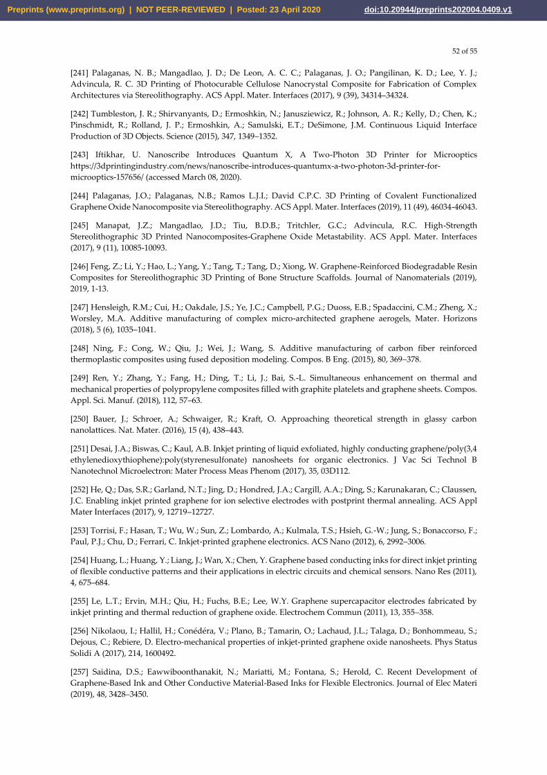
52 of 55
[241] Palaganas, N. B.; Mangadlao, J. D.; De Leon, A. C. C.; Palaganas, J. O.; Pangilinan, K. D.; Lee, Y. J.;
Advincula, R. C. 3D Printing of Photocurable Cellulose Nanocrystal Composite for Fabrication of Complex
Architectures via Stereolithography. ACS Appl. Mater. Interfaces (2017), 9 (39), 34314–34324.
[242] Tumbleston, J. R.; Shirvanyants, D.; Ermoshkin, N.; Janusziewicz, R.; Johnson, A. R.; Kelly, D.; Chen, K.;
Pinschmidt, R.; Rolland, J. P.; Ermoshkin, A.; Samulski, E.T.; DeSimone, J.M. Continuous Liquid Interface
Production of 3D Objects. Science (2015), 347, 1349–1352.
[243] Iftikhar, U. Nanoscribe Introduces Quantum X, A Two-Photon 3D Printer for Microoptics
https://3dprintingindustry.com/news/nanoscribe-introduces-quantumx-a-two-photon-3d-printer-for-
microoptics-157656/ (accessed March 08, 2020).
[244] Palaganas, J.O.; Palaganas, N.B.; Ramos L.J.I.; David C.P.C. 3D Printing of Covalent Functionalized
Graphene Oxide Nanocomposite via Stereolithography. ACS Appl. Mater. Interfaces (2019), 11 (49), 46034-46043.
[245] Manapat, J.Z.; Mangadlao, J.D.; Tiu, B.D.B.; Tritchler, G.C.; Advincula, R.C. High-Strength
Stereolithographic 3D Printed Nanocomposites-Graphene Oxide Metastability. ACS Appl. Mater. Interfaces
(2017), 9 (11), 10085-10093.
[246] Feng, Z.; Li, Y.; Hao, L.; Yang, Y.; Tang, T.; Tang, D.; Xiong, W. Graphene-Reinforced Biodegradable Resin
Composites for Stereolithographic 3D Printing of Bone Structure Scaffolds. Journal of Nanomaterials (2019),
2019, 1-13.
[247] Hensleigh, R.M.; Cui, H.; Oakdale, J.S.; Ye, J.C.; Campbell, P.G.; Duoss, E.B.; Spadaccini, C.M.; Zheng, X.;
Worsley, M.A. Additive manufacturing of complex micro-architected graphene aerogels, Mater. Horizons
(2018), 5 (6), 1035–1041.
[248] Ning, F.; Cong, W.; Qiu, J.; Wei, J.; Wang, S. Additive manufacturing of carbon fiber reinforced
thermoplastic composites using fused deposition modeling. Compos. B Eng. (2015), 80, 369–378.
[249] Ren, Y.; Zhang, Y.; Fang, H.; Ding, T.; Li, J.; Bai, S.-L. Simultaneous enhancement on thermal and
mechanical properties of polypropylene composites filled with graphite platelets and graphene sheets. Compos.
Appl. Sci. Manuf. (2018), 112, 57–63.
[250] Bauer, J.; Schroer, A.; Schwaiger, R.; Kraft, O. Approaching theoretical strength in glassy carbon
nanolattices. Nat. Mater. (2016), 15 (4), 438–443.
[251] Desai, J.A.; Biswas, C.; Kaul, A.B. Inkjet printing of liquid exfoliated, highly conducting graphene/poly(3,4
ethylenedioxythiophene):poly(styrenesulfonate) nanosheets for organic electronics. J Vac Sci Technol B
Nanotechnol Microelectron: Mater Process Meas Phenom (2017), 35, 03D112.
[252] He, Q.; Das, S.R.; Garland, N.T.; Jing, D.; Hondred, J.A.; Cargill, A.A.; Ding, S.; Karunakaran, C.; Claussen,
J.C. Enabling inkjet printed graphene for ion selective electrodes with postprint thermal annealing. ACS Appl
Mater Interfaces (2017), 9, 12719–12727.
[253] Torrisi, F.; Hasan, T.; Wu, W.; Sun, Z.; Lombardo, A.; Kulmala, T.S.; Hsieh, G.-W.; Jung, S.; Bonaccorso, F.;
Paul, P.J.; Chu, D.; Ferrari, C. Inkjet-printed graphene electronics. ACS Nano (2012), 6, 2992–3006.
[254] Huang, L.; Huang, Y.; Liang, J.; Wan, X.; Chen, Y. Graphene based conducting inks for direct inkjet printing
of flexible conductive patterns and their applications in electric circuits and chemical sensors. Nano Res (2011),
4, 675–684.
[255] Le, L.T.; Ervin, M.H.; Qiu, H.; Fuchs, B.E.; Lee, W.Y. Graphene supercapacitor electrodes fabricated by
inkjet printing and thermal reduction of graphene oxide. Electrochem Commun (2011), 13, 355–358.
[256] Nikolaou, I.; Hallil, H.; Conédéra, V.; Plano, B.; Tamarin, O.; Lachaud, J.L.; Talaga, D.; Bonhommeau, S.;
Dejous, C.; Rebiere, D. Electro-mechanical properties of inkjet-printed graphene oxide nanosheets. Phys Status
Solidi A (2017), 214, 1600492.
[257] Saidina, D.S.; Eawwiboonthanakit, N.; Mariatti, M.; Fontana, S.; Herold, C. Recent Development of
Graphene-Based Ink and Other Conductive Material-Based Inks for Flexible Electronics. Journal of Elec Materi
(2019), 48, 3428–3450.
Preprints (www.preprints.org) | NOT PEER-REVIEWED | Posted: 23 April 2020 doi:10.20944/preprints202004.0409.v1
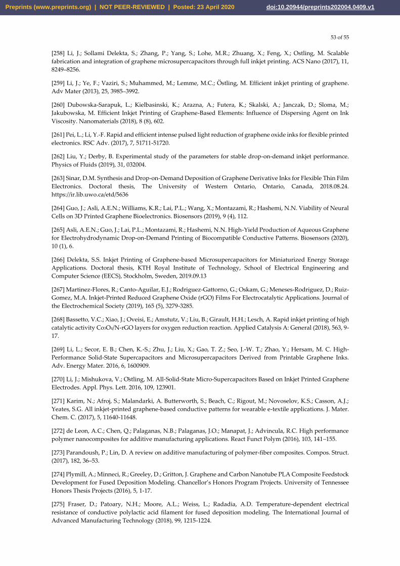
53 of 55
[258] Li, J.; Sollami Delekta, S.; Zhang, P.; Yang, S.; Lohe, M.R.; Zhuang, X.; Feng, X.; Ostling, M. Scalable
fabrication and integration of graphene microsupercapacitors through full inkjet printing. ACS Nano (2017), 11,
8249–8256.
[259] Li, J.; Ye, F.; Vaziri, S.; Muhammed, M.; Lemme, M.C.; Östling, M. Efficient inkjet printing of graphene.
Adv Mater (2013), 25, 3985–3992.
[260] Dubowska-Sarapuk, L.; Kielbasinski, K.; Arazna, A.; Futera, K.; Skalski, A.; Janczak, D.; Sloma, M.;
Jakubowska, M. Efficient Inkjet Printing of Graphene-Based Elements: Influence of Dispersing Agent on Ink
Viscosity. Nanomaterials (2018), 8 (8), 602.
[261] Pei, L.; Li, Y.-F. Rapid and efficient intense pulsed light reduction of graphene oxide inks for flexible printed
electronics. RSC Adv. (2017), 7, 51711-51720.
[262] Liu, Y.; Derby, B. Experimental study of the parameters for stable drop-on-demand inkjet performance.
Physics of Fluids (2019), 31, 032004.
[263] Sinar, D.M. Synthesis and Drop-on-Demand Deposition of Graphene Derivative Inks for Flexible Thin Film
Electronics. Doctoral thesis, The University of Western Ontario, Ontario, Canada, 2018.08.24.
https://ir.lib.uwo.ca/etd/5636
[264] Guo, J.; Asli, A.E.N.; Williams, K.R.; Lai, P.L.; Wang, X.; Montazami, R.; Hashemi, N.N. Viability of Neural
Cells on 3D Printed Graphene Bioelectronics. Biosensors (2019), 9 (4), 112.
[265] Asli, A.E.N.; Guo, J.; Lai, P.L.; Montazami, R.; Hashemi, N.N. High-Yield Production of Aqueous Graphene
for Electrohydrodynamic Drop-on-Demand Printing of Biocompatible Conductive Patterns. Biosensors (2020),
10 (1), 6.
[266] Delekta, S.S. Inkjet Printing of Graphene-based Microsupercapacitors for Miniaturized Energy Storage
Applications. Doctoral thesis, KTH Royal Institute of Technology, School of Electrical Engineering and
Computer Science (EECS), Stockholm, Sweden, 2019.09.13
[267] Martinez-Flores, R.; Canto-Aguilar, E.J.; Rodriguez-Gattorno, G.; Oskam, G.; Meneses-Rodriguez, D.; Ruiz-
Gomez, M.A. Inkjet-Printed Reduced Graphene Oxide (rGO) Films For Electrocatalytic Applications. Journal of
the Electrochemical Society (2019), 165 (5), 3279-3285.
[268] Bassetto, V.C.; Xiao, J.; Oveisi, E.; Amstutz, V.; Liu, B.; Girault, H.H.; Lesch, A. Rapid inkjet printing of high
catalytic activity Co3O4/N-rGO layers for oxygen reduction reaction. Applied Catalysis A: General (2018), 563, 9-
17.
[269] Li, L.; Secor, E. B.; Chen, K.-S.; Zhu, J.; Liu, X.; Gao, T. Z.; Seo, J.-W. T.; Zhao, Y.; Hersam, M. C. High-
Performance Solid-State Supercapacitors and Microsupercapacitors Derived from Printable Graphene Inks.
Adv. Energy Mater. 2016, 6, 1600909.
[270] Li, J.; Mishukova, V.; Ostling, M. All-Solid-State Micro-Supercapacitors Based on Inkjet Printed Graphene
Electrodes. Appl. Phys. Lett. 2016, 109, 123901.
[271] Karim, N.; Afroj, S.; Malandarki, A. Butterworth, S.; Beach, C.; Rigout, M.; Novoselov, K.S.; Casson, A.J.;
Yeates, S.G. All inkjet-printed graphene-based conductive patterns for wearable e-textile applications. J. Mater.
Chem. C. (2017), 5, 11640-11648.
[272] de Leon, A.C.; Chen, Q.; Palaganas, N.B.; Palaganas, J.O.; Manapat, J.; Advincula, R.C. High performance
polymer nanocomposites for additive manufacturing applications. React Funct Polym (2016), 103, 141–155.
[273] Parandoush, P.; Lin, D. A review on additive manufacturing of polymer-fiber composites. Compos. Struct.
(2017), 182, 36–53.
[274] Plymill, A.; Minneci, R.; Greeley, D.; Gritton, J. Graphene and Carbon Nanotube PLA Composite Feedstock
Development for Fused Deposition Modeling. Chancellor’s Honors Program Projects. University of Tennessee
Honors Thesis Projects (2016), 5, 1-17.
[275] Fraser, D.; Patoary, N.H.; Moore, A.L.; Weiss, L.; Radadia, A.D. Temperature-dependent electrical
resistance of conductive polylactic acid filament for fused deposition modeling. The International Journal of
Advanced Manufacturing Technology (2018), 99, 1215-1224.
Preprints (www.preprints.org) | NOT PEER-REVIEWED | Posted: 23 April 2020 doi:10.20944/preprints202004.0409.v1
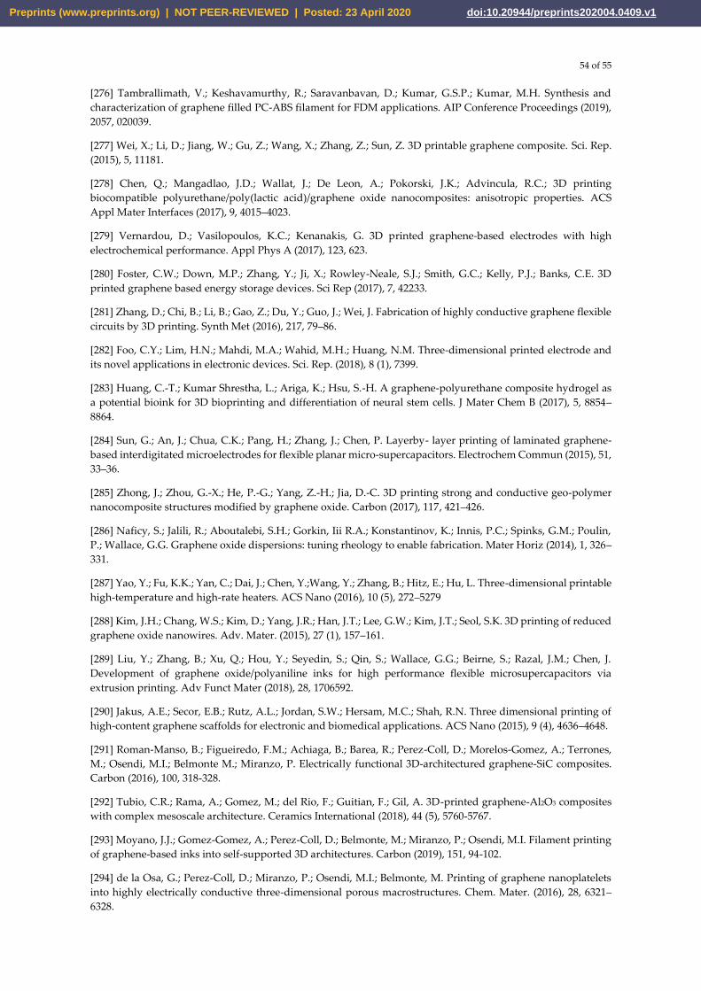
54 of 55
[276] Tambrallimath, V.; Keshavamurthy, R.; Saravanbavan, D.; Kumar, G.S.P.; Kumar, M.H. Synthesis and
characterization of graphene filled PC-ABS filament for FDM applications. AIP Conference Proceedings (2019),
2057, 020039.
[277] Wei, X.; Li, D.; Jiang, W.; Gu, Z.; Wang, X.; Zhang, Z.; Sun, Z. 3D printable graphene composite. Sci. Rep.
(2015), 5, 11181.
[278] Chen, Q.; Mangadlao, J.D.; Wallat, J.; De Leon, A.; Pokorski, J.K.; Advincula, R.C.; 3D printing
biocompatible polyurethane/poly(lactic acid)/graphene oxide nanocomposites: anisotropic properties. ACS
Appl Mater Interfaces (2017), 9, 4015–4023.
[279] Vernardou, D.; Vasilopoulos, K.C.; Kenanakis, G. 3D printed graphene-based electrodes with high
electrochemical performance. Appl Phys A (2017), 123, 623.
[280] Foster, C.W.; Down, M.P.; Zhang, Y.; Ji, X.; Rowley-Neale, S.J.; Smith, G.C.; Kelly, P.J.; Banks, C.E. 3D
printed graphene based energy storage devices. Sci Rep (2017), 7, 42233.
[281] Zhang, D.; Chi, B.; Li, B.; Gao, Z.; Du, Y.; Guo, J.; Wei, J. Fabrication of highly conductive graphene flexible
circuits by 3D printing. Synth Met (2016), 217, 79–86.
[282] Foo, C.Y.; Lim, H.N.; Mahdi, M.A.; Wahid, M.H.; Huang, N.M. Three-dimensional printed electrode and
its novel applications in electronic devices. Sci. Rep. (2018), 8 (1), 7399.
[283] Huang, C.-T.; Kumar Shrestha, L.; Ariga, K.; Hsu, S.-H. A graphene-polyurethane composite hydrogel as
a potential bioink for 3D bioprinting and differentiation of neural stem cells. J Mater Chem B (2017), 5, 8854–
8864.
[284] Sun, G.; An, J.; Chua, C.K.; Pang, H.; Zhang, J.; Chen, P. Layerby- layer printing of laminated graphene-
based interdigitated microelectrodes for flexible planar micro-supercapacitors. Electrochem Commun (2015), 51,
33–36.
[285] Zhong, J.; Zhou, G.-X.; He, P.-G.; Yang, Z.-H.; Jia, D.-C. 3D printing strong and conductive geo-polymer
nanocomposite structures modified by graphene oxide. Carbon (2017), 117, 421–426.
[286] Naficy, S.; Jalili, R.; Aboutalebi, S.H.; Gorkin, Iii R.A.; Konstantinov, K.; Innis, P.C.; Spinks, G.M.; Poulin,
P.; Wallace, G.G. Graphene oxide dispersions: tuning rheology to enable fabrication. Mater Horiz (2014), 1, 326–
331.
[287] Yao, Y.; Fu, K.K.; Yan, C.; Dai, J.; Chen, Y.;Wang, Y.; Zhang, B.; Hitz, E.; Hu, L. Three-dimensional printable
high-temperature and high-rate heaters. ACS Nano (2016), 10 (5), 272–5279
[288] Kim, J.H.; Chang, W.S.; Kim, D.; Yang, J.R.; Han, J.T.; Lee, G.W.; Kim, J.T.; Seol, S.K. 3D printing of reduced
graphene oxide nanowires. Adv. Mater. (2015), 27 (1), 157–161.
[289] Liu, Y.; Zhang, B.; Xu, Q.; Hou, Y.; Seyedin, S.; Qin, S.; Wallace, G.G.; Beirne, S.; Razal, J.M.; Chen, J.
Development of graphene oxide/polyaniline inks for high performance flexible microsupercapacitors via
extrusion printing. Adv Funct Mater (2018), 28, 1706592.
[290] Jakus, A.E.; Secor, E.B.; Rutz, A.L.; Jordan, S.W.; Hersam, M.C.; Shah, R.N. Three dimensional printing of
high-content graphene scaffolds for electronic and biomedical applications. ACS Nano (2015), 9 (4), 4636–4648.
[291] Roman-Manso, B.; Figueiredo, F.M.; Achiaga, B.; Barea, R.; Perez-Coll, D.; Morelos-Gomez, A.; Terrones,
M.; Osendi, M.I.; Belmonte M.; Miranzo, P. Electrically functional 3D-architectured graphene-SiC composites.
Carbon (2016), 100, 318-328.
[292] Tubio, C.R.; Rama, A.; Gomez, M.; del Rio, F.; Guitian, F.; Gil, A. 3D-printed graphene-Al2O3 composites
with complex mesoscale architecture. Ceramics International (2018), 44 (5), 5760-5767.
[293] Moyano, J.J.; Gomez-Gomez, A.; Perez-Coll, D.; Belmonte, M.; Miranzo, P.; Osendi, M.I. Filament printing
of graphene-based inks into self-supported 3D architectures. Carbon (2019), 151, 94-102.
[294] de la Osa, G.; Perez-Coll, D.; Miranzo, P.; Osendi, M.I.; Belmonte, M. Printing of graphene nanoplatelets
into highly electrically conductive three-dimensional porous macrostructures. Chem. Mater. (2016), 28, 6321–
6328.
Preprints (www.preprints.org) | NOT PEER-REVIEWED | Posted: 23 April 2020 doi:10.20944/preprints202004.0409.v1

55 of 55
[295] Shen, C.; Calderon, J.E.; Barrios, E.; Soliman, M.; Khater, A.; Jeyaranjan, A.; Tetard, L.; Gordon, A.; Seal, S.;
Zhai, L. Anisotropic electrical conductivity in polymer derived ceramics induced by graphene aerogels. J.
Mater.Chem.C. (2017), 5, 11708-11716.
[296] Bernardo, E.; Fiocco, L.; Parcianello, G.; Storti, E.; Colombo, P. Advanced Ceramics from Preceramic
Polymers Modified at the Nano-Scale-A Review. Materials (2014), 7 (3), 1927-1956.
[297] Pierin, G.; Grotta, C.; Colombo, P.; Mattevi, C. Direct Ink Writing of micrometric SiOC ceramic structures
using a preceramic polymer. Journal of the European Ceramic Society (2016), 36 (7), 1589-1594.
[298] Manso, B.R.; Moyano, J.J.; Perez-Coll, D.; Belmonte, M.; Miranzo, P.; Osendi, M.I. Polymer-derived ceramic-
graphene oxide architected composite with high electrical conductivity and enhanced thermal resistance. Journal
of the European Ceramic Society (2018), 38 (5), 2265-2271.
[299] Moyano, J.J.; Mosa, J.; Aparicio, M.; Pérez-Coll, D.; Belmonte, M.; Miranzo, P.; Osendi, M.I. Strong and light
cellular silicon carbonitride–Reduced graphene oxide material with enhanced electrical conductivity and
capacitive response. Additive Manufacturing (2019), 30, 100849.
[300] You, X.; Yang, J.; Huang, K.; Wang, M.; Zhang, X.; Dong, S. Multifunctional silicon carbide matrix
composites optimized by three-dimensional graphene scaffolds. Carbon (2019), 155, 215-222.
[301] Rossi, S.; Puglisi, A.; Benaglia, M. Additive Manufacturing Technologies: 3D Printing in Organic Synthesis.
ChemCatChem (2018), 10, 1512.
Preprints (www.preprints.org) | NOT PEER-REVIEWED | Posted: 23 April 2020 doi:10.20944/preprints202004.0409.v1

![Development of 3D Printing Technology for the Manufacture ... · [3], coating [4], ink-jet printing [10], selective laser melting [11] and 3D FDM printing [12]. However, these methods](https://img.pdfslide.us/doc/110x75/5fd5b292d01942596b7c5bdb/development-of-3d-printing-technology-for-the-manufacture-3-coating-4.jpg)