Embed Size (px)
Citation preview
GEOPHYSICS. VOL. 48, NO. II (NOVEMBER 1983); P. 1514-1524, 9 FIGS
Reverse time migration
Edip Baysal*, Dan D. KosloffS, and John W. C. Sherwood9
ABSTRACT
Migration of stacked or zero-offset sections is based on deriving the wave amplitude in space from wave field observations at the surface. Conventionally this calcula- tion has been carried out through a depth extrapola- tion.
We examine the alternative of carrying out the migra- tion through a reverse time extrapolation. This ap- proach may offer improvements over existing migration methods, especially in cases of steeply dipping structures with strong velocity contrasts. This migration method is tested using appropriate synthetic data sets.
INTRODUCTION
Migration of stacked or zero-offset data considered to con- sist of primary reflections only has usually been achieved through a downward continuation of the surface data (Claer- bout and Doherty, 1972; Loewenthal et al, 1976; Stolt, 1978; Bcrklrout; i98G). Tlnmc Final migratc& s&on is t+rtm given ‘by the amplitude of the extrapolated field at time zero as a function of depth (Loewenthal et al, 1976; Judson et al, 1980). The velocity for the calculations should be taken as half the actual velocity in the medium (Loewenthal et al, 1976).
The imaging principle inherent in the migration of stacked sections permits a different approach to migration based on reverse time marching instead of a depth extrapolation. The stacked section is considered as a surface boundary condition for a reverse operation to the modeling type wave calculations that step forward in time (Kelly et al, 1976; Kosloff and Baysal, 1982). The calculations are carried out in reversed time from the time-of the-last sample on the time section until time~zero when the amplitudes in all space are considered as the final migrated section. If the velocities for the migration are chosen correctly, the wave field at time zero should be coincident with the reflecting horizons in the medium.
Reverse time migration may offer a number of improvements over conventional depth extrapolation. In particular, the posing of the migration problem as an extrapolation in timeinstead of in depth avoids the problems associated with evanes-
cent energy (Kosloff and Baysal, 1983). Furthermore, this paper will show that it is possible to use wave equations containing no dip limitations for time stepping schemes and that a steep- dip depth migration can be achieved with ease.
In the following sections, wc outline the main ingredients of reverse time migration and present a number of examples which shed light on its features.
DEPTH MIGRATION AS A REVERSE EXTRAPOI,ATION IN time
The basis for migration of stacked time sections is the “ex-
ploding reflector model” (Loeuenthal et al, 1976). According to this model, an approximation to a stacked section can be obtained in a single experiment by replacing the subsurface with a medium containing half the actual velocities in the earth, and by initiating explosive sources at time zero on all the reflecting boundaries. With this model, the recorded surface time section approximates the stacked or zero-offset section which would be collected over the same region (Loewenthal et al, 1976).
The purpose of migration, based on the exploding reflector model, IS to recover the amplitudes at time zero which give the location and strength of the reflectors. Let P(x, z = 0, t) denote the surface recorded time section with x the horizontal mid- point coordinate along the seismic line and z the depth. The migrated section then becomes P(x, z, t = 0). In the reverse time depth migration, it is assumed that P(x, z, t) = 0 for t > TL where T,, is the last recorded time sample. In other words, it is assumed that after this time the energy has propagated away from the subsurface underneath the seismic line. The migration is then formulated as a wave propagation problem in which the waves are generated from the time reversed stacked or zero- offset section P(x, z = 0, t) which is applied as a surface bound- ary condition.
There are a number of possibilities for choosing a wave equation for the migration. Since the subsurface recorded common-depth-point (CDP) stacked section is ideally free of multiple reflections, it seems appropriate to use a wave equa- tion which avoids layer reflections. Thus, for the present study,
(Text continued on p. 15/Y)
Manuscript received by the Editor August 30, 1982; revised manuscript received December 14, 1982. *Geophysical Development Corporation and Seismic Acoustics Laboratory, Houston, TX. IGeophysics Department, Tel-Aviv University, Tel-Abiv, Israel and Seismic Acoustics Laboralory of the University of Houston $Geophysical Development Corporation, 8401 Westheimer. Houston, TX 77063. CJ 1983 Society of Exploration Geophysicists. All rights reserved.
1514
Downloaded 06 Jun 2012 to 72.20.129.98. Redistribution subject to SEG license or copyright; see Terms of Use at http://segdl.org/
Reverse time Migration 1515
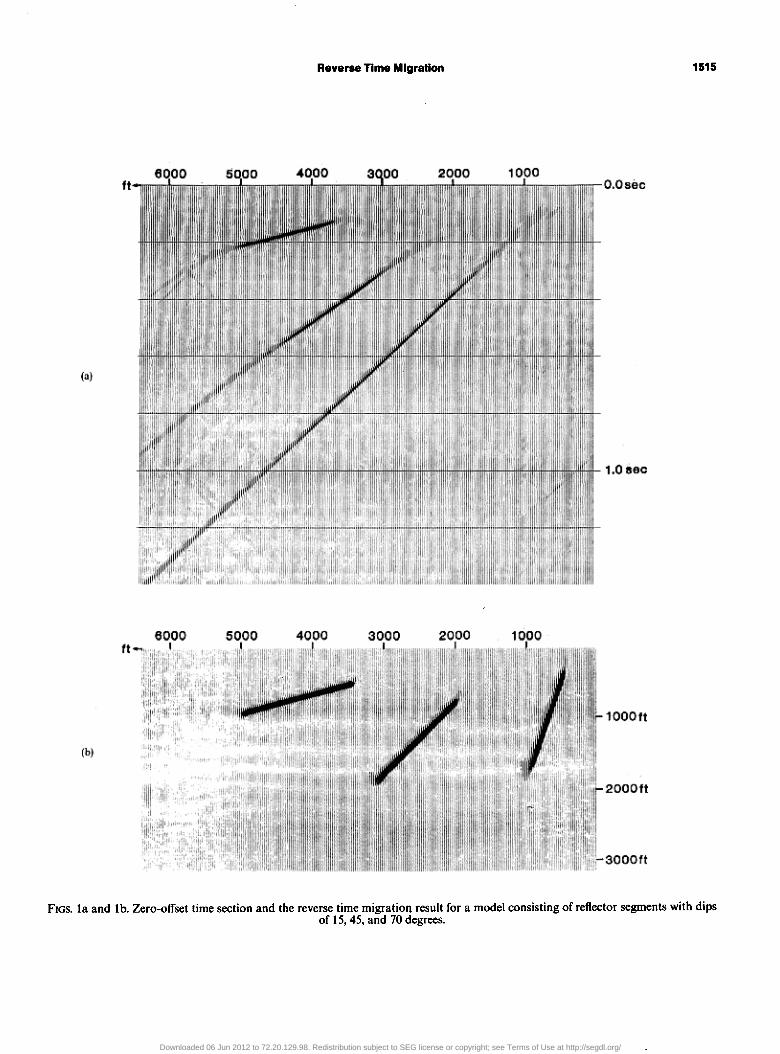
FIGS. la and lb. Zero-offset time section and the reverse time migration result for a model consisting of reflector segments with dips of 15,45, and 70 degrees.
Downloaded 06 Jun 2012 to 72.20.129.98. Redistribution subject to SEG license or copyright; see Terms of Use at http://segdl.org/
1516 Baysal et al
REEF 5 5. 10. ++++l+*++l*t*+~t+++ +++t +++,~+++‘fj;+++~~+++~~~+++~~++~~~+++~+++~+++~++++~++t+~+++*~++t+l~
is. y. q5. 70. 75. fxl. 85. 90.
. . . . . ::..... _.......,........... . . . . . . . . . . . . . . . . . . . . . . . . _.............................. . . . . . . . . . . . . . . . . . . . . . . . . . . . . . . . . . . . . . . . . . . . . . . . . . . . . . . . . . . . . . . . . . . . . . . . . . . . . . . . . . . . . . . . . . . . . . . . . . . . . . . . . . . . . . . . . . . . . . . . . . . . . . . . . . . . . . . . . . . . . . . . . . . . . . . . . . . . . . . . . . . . . . . . . . . . . . . . . . . . . . . . . . . . ..I........................................................................................................................ . . . . . . . . . . . . . . . . . . . . . . . ..~........................................................................................................................................
DEPTH
ZSR
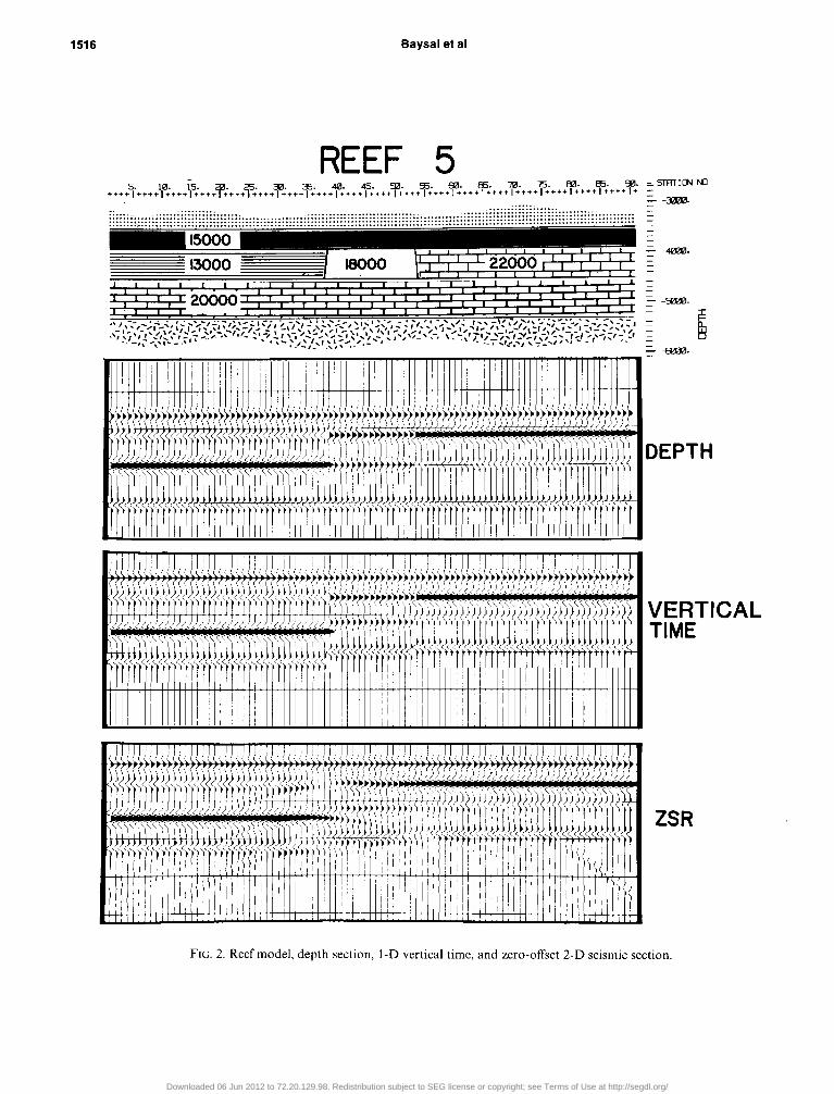
FIG. 2. Reef model, depth section, 1-D vertical time and zero-offset 2-D seismic section.
Downloaded 06 Jun 2012 to 72.20.129.98. Redistribution subject to SEG license or copyright; see Terms of Use at http://segdl.org/
Reverse time Migration
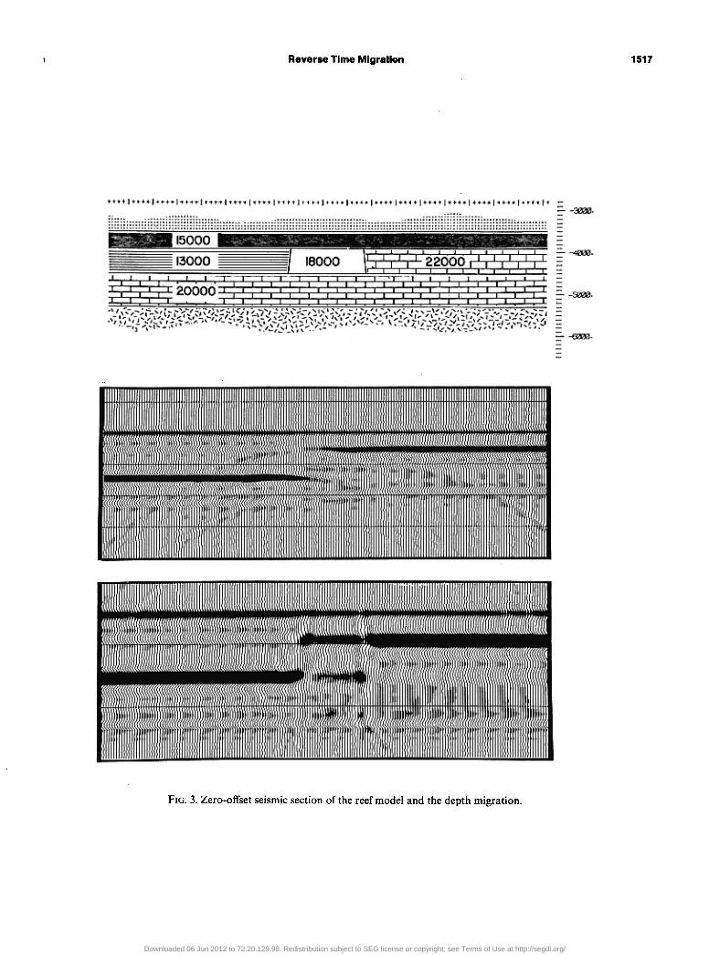
FIG. 3. Zero-offset seismic section of the reef model and the depth migration.
1517
Downloaded 06 Jun 2012 to 72.20.129.98. Redistribution subject to SEG license or copyright; see Terms of Use at http://segdl.org/
1518 Baysal et al
....... :; ............ .................... ..... ......................... ................................ ....................................... ................................................... .............................................................................................. ...................................................... ......................................................... .................................. . . . . . . . . . . . . . . . . . . . . . . . . ......................................................................................
r -mm. -
--40iEi.
r-50&3.
--6?00.
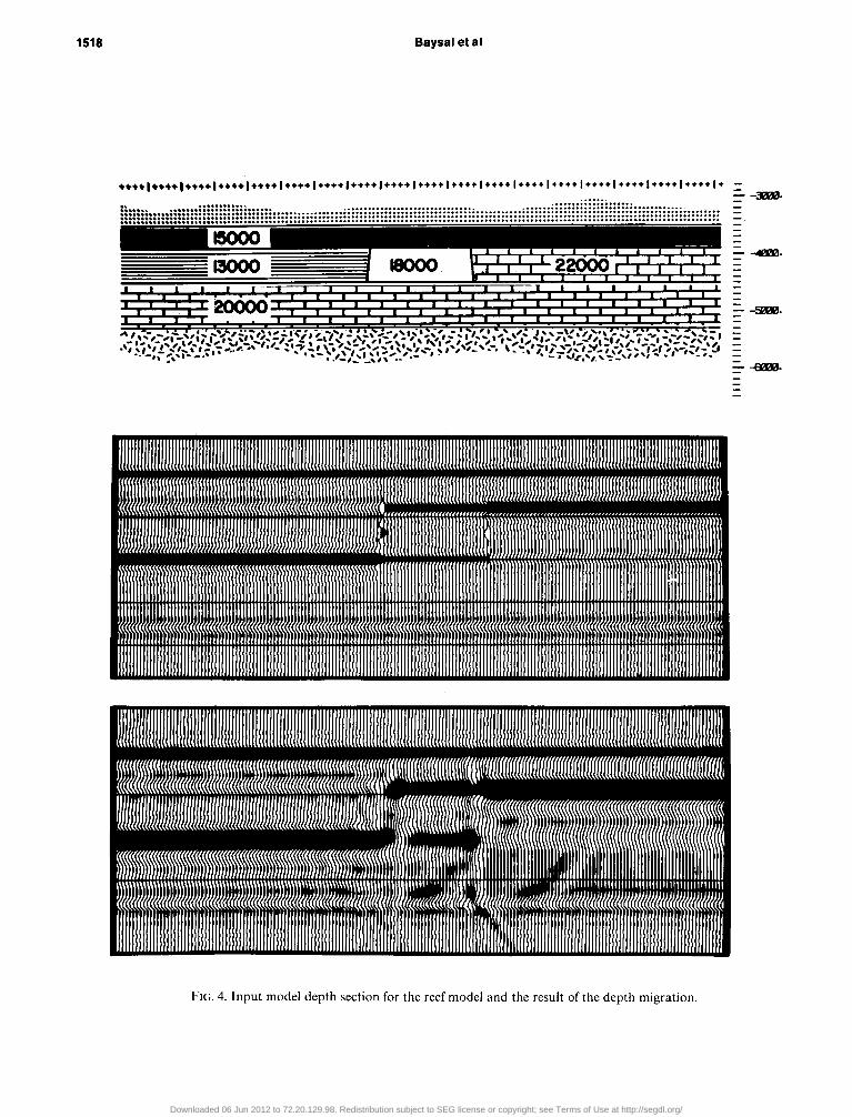
FIG. 4. Input model depth section for the reef model and the result of the depth migration.
Downloaded 06 Jun 2012 to 72.20.129.98. Redistribution subject to SEG license or copyright; see Terms of Use at http://segdl.org/
Reverse time Migration 1519
we chose the go-degree dip wave equation first presented by Gazdag (1981):
In equation (1) P(x, i, t) denotes the wave field (related either to the pressure or to the vertical velocity component), c(x, Z) is the velocity field, and x and Z, respectively, are the horizontal and vertical coordinates. The square root derivative operator does not have an explicit representation in the spatial domain, but it can be handled in a natural manner using spatial Fourier transforms (Gazdag, 1980, 1981; Kosloff and Baysal, 1982, 1983). Using equation (l), a numerical estimate can be made of the time derivative of P at time T. P(x, z, t = T) is first
2-D Fourier transformed to the wavenumber domain (k,, k,) using the fast Fourier transform algorithm. Subsequent multi- plication by [sign (k,)i(kz + k:)‘~‘]. 2-D Fourier inversion back to the (x, Z) domain. and multiplication by the spatially varying velocity c(x, -_) yields the time derivative P(x, z, r = 7’). This is now approximated by the centered finite difference of
P(x, e, t=7’-At)andP(x,z,t=7’+At):
CP(X, Z, T + At) - P(.x, I, T ~ At)]/2At = &x, z, 7’). (2)
Hence, knowledge of the wave field P(x, z, t) at times (T + At) and T enables estimation of P(x, 2. t = T - At). Since the wave field is propagated back down toward the reflectors, it is physi- cally impossible for this method to yield a sensible value for P(x,,z = 0, T - At). Instead these values at the z = 0 boundary
16QOOft Oft
8000
10000
- Oft
-6OOOft
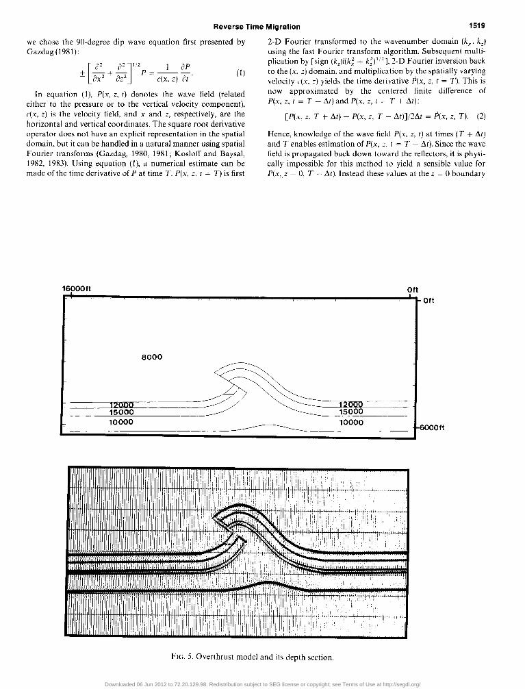
FIG. 5. Overthrust model and its depth section.
Downloaded 06 Jun 2012 to 72.20.129.98. Redistribution subject to SEG license or copyright; see Terms of Use at http://segdl.org/
1520 Baysal et al
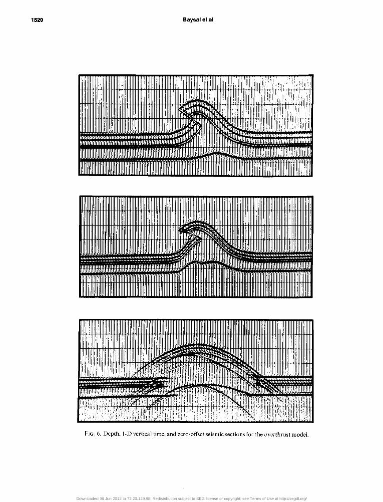
FIG. 6. Depth, 1-D vertical time and zero-offset seismic sections for the overthrust model.
Downloaded 06 Jun 2012 to 72.20.129.98. Redistribution subject to SEG license or copyright; see Terms of Use at http://segdl.org/
Reverse time Migration 1521
are provided from the stacked time section P(x, z = 0, r), 0 < t < TL. The calculations proceed from time t = TL to timet = 0, the initial wave field being taken as zero at times (TL + At) and (TL + 2At).
This approach utilizing equations (1) and (2) appears emi- nently suitable for reverse time migration because it applies to dips reaching 90 degrees and it permits both vertical and lateral velocity variations. The method is also free of numerical disper- sion and instability from exponentially growing evanescent waves.
EXAMPLES
The algorithm is demonstrated here with synthetic data. Rather than running the same program forward in time to generate input time sections, other algorithms were used to create the synthetic time sections.
The first example is a test for accuracy as a function of dip. The input model consists of three reflector segments with dips of 15, 45, and 70 degrees. The velocity of the medium is 8000 ft/sec. The time section resulting fromf-k modeling (Stolt, 1978)
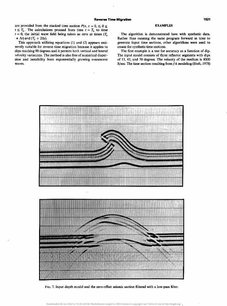
FIG. 7. Input depth model and the zero-offset seismic section filtered with a low-pass filter.
Downloaded 06 Jun 2012 to 72.20.129.98. Redistribution subject to SEG license or copyright; see Terms of Use at http://segdl.org/
1522 Baysal et al
and the corresponding reverse time migration are shown in Figures la and lb, respectively. It is apparent that the events have been migrated with crisp definition and no noticeable dispersion. The dips agree with those of the original model.
The second example is a stratigraphic model featuring a 600 ft high pinnacle reef that is approximately 1600 ft wide at the base. This reef model, its depth section, 1-D vertical time sec- tion, and zero-offset 2-D time section are shown in Figure 2. The zero-offset seismic section was obtained from a modified Kirchhoff modeling program (Larson and Hilterman, 1976). Note the dead zone that is on the left-hand side of the top of the reef reflection in the zero-offset section. This dead zone occurs
because the reflection coefficient changes polarity laterally and, thus, for shotpoints near this reflection coefficientdiscontinuity the wavefront sees half of a positive reflecting boundary and half of a negative reflecting boundary. Notice also that the velocity pull-up is not as simple as the 1-D vertical time section suggests. The pull-up on the deeper reflector appears to be dipping.
In the migration the corrrect velocity field was used. Figure 3 shows the geologic model, its zero-offset seismic section, and the depth migration result. The wavelet used in the zero-offset seismic section was a 28 Hz Ricker wavelet. Prior to migration the input section was filtered with a low-pass filter with a
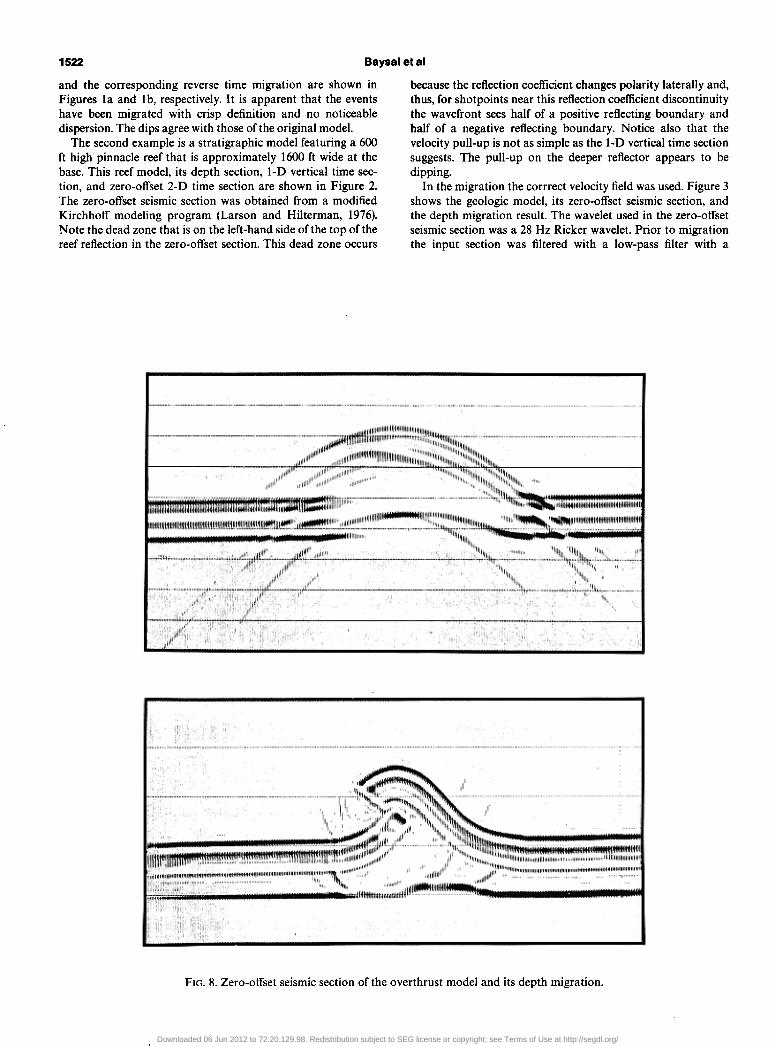
FIG. 8. Zero-offset seismic section of the overthrust model and its depth migration.
Downloaded 06 Jun 2012 to 72.20.129.98. Redistribution subject to SEG license or copyright; see Terms of Use at http://segdl.org/
Reverse lime Migration 1523
cut-off frequency of 20 Hz in order to shorten the calculation time (the time step size used in the migration was 1 msec). Thus in Figure 3 the zero-offset section has a sharper wavelet than the depth migration result. Also the vertical scale for the migra- tion result is depth z, and therefore the wavelet observed in the the migrated section is a spatial wavelet. The trace spacing in the zero-offset seismic section was 50 ft, and in the migration a grid spacing of 50 ft (Ax = AZ = 50 ft) was used. The migrated depth section should be compared against the input depth model in order to examine the results. Figure 4 shows this comparison. The location of the reef is correctly presented in the depth migrated section. The change in the reflection coef-
ficient on both sides of the reef also conforms with the geologic model.
The third example is more representative of a structural model. Figure 5 shows the model and its depth section. The velocities used in the model range from 8000 to 15,000 fi/sec. The depth section, 1-D time section, and zero-offset seismic section are presented in Figure 6. The zero-offset seismic sec- tion presents a difficult case for interpretation, and it is obvious that the migration of this seismic section will be necessary for a sensible interpretation.
Trace spacing for this model was 50 ft. In the depth migra- tion process a grid spacing of 50 ft (Ax = AZ = 50 ft) was used.
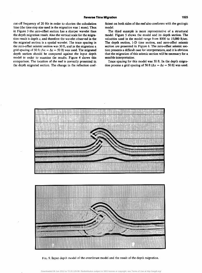
FIG. 9. Input depth model of the overthrust model and the result of the depth migration.
Downloaded 06 Jun 2012 to 72.20.129.98. Redistribution subject to SEG license or copyright; see Terms of Use at http://segdl.org/
1524 Baysal et al
The zero-offset seismic section was filtered with a low-pass filter of 20 Hz cut-off frequency, which allowed a time sample rate of 1 msec to be used in the migration process. The filtered input data are shown in Figure 7.
The depth migration result is shown in Figure 8, together with the input zero-offset section. The vertical axis of the zero- offset section is time whereas in the migration result the verti- cal scale represents depth in feet. Figure 8 indicates that migra- tion of seismic data is a very important tool in interpretation. Since the input model was synthetic, the migration result can be compared against the input depth model. Figure 9 shows that the tesult of such a comparison is satisfactory. In the migration result the continuity of the folded sediments and the sharpness of the fault zone illustrate the accuracy of the algorithm. The deepest boundary of the geologic model under the overthrust zone is not accurately reconstructed. It is probable that the fault lies not with the depth migration but rather with the modeling program producing the zero-offset seismic section. This was a ray-tracing program (modified Kirchhoff modeling) which may be expected to be inaccurate with such a complex velocity model.
CONCLUSION
We have presented a migration method for stacked or zero- offset sections based on a reverse time extrapolation, Theoreti- cal considerations and the synthetic examples presented indi- cate that reverse time depth migration can handle structures containing steep dips and strong velocity contrasts. In compli- cated areas this migration may offer a viabie aiternative to migration based on depth extrapolation.
ACKNOWLEDGMENTS
It is a pleasure to acknowledge the financial support and the provision of excellent computer facilities for two of the authors from the Seismic Acoustics Laboratory of the Univ. of Hou- ston Also we are very appreciative of the advice and assistance of Fred Hilterman in the construction of the synthetic models and for his enthusiastic participation in several lengthy dis- cussions.
REFERENCES
Berkhout, A. J., 1980, Seismic migration: Elsevier Sci. Pub]. Co., Am- sterdam.
Claerbout, J., and Doherty, S., 1972, Downward continuation of moveout corrected seismograms: Geophysics, v. 37, p. 741-768.
Gazdag, J., 1980, Wave equation migration with the accurate space derivative method: geophys Proso.. v. 28. D. 60-70.
~ 1981, Modeling of the acous& waveequation with transform methods: Geophysics, v. 46, p. 854-859.
Judson. D. R., Lin, J., Schultz, P. S.. and Sherwood, J. W. C., 1980, Depth migration after stack: Geophysics, v. 45, p. 361-375.
Kelly, K. R., Ward. R. W., Treitel, S.. and Alford, R. M., 1976, Synthetic seismograms: a finite-difference approach: Geophysics, v. 41, p, 2- 17 L,.
Kosloff, D. D.. and Baysal. E., 19X2, Forward modeling by a Fourier method: Geophysics, v. 47, p. 140221412.
~ 1983, Migration with the full acoustic wave equation: Geo- physics, v. 48, p. 6777687.
Larson, D., and Hilterman, F. J.. 1976, Diffractions: their generation and interpretation use: Presented at the 29th Annual Midwestern SEC Meeting, Dallas.
Loewenthal, D., Lu, L.. Roberson, R., and Sherwood, J. W. C., 1976, The wave equation applied to migration: Geophys. Prosp., v. 24, n. 380-399.
S&It, R., 1978, Migration by Fourier transform: Geophysics, v. 43, p. 23348.
Downloaded 06 Jun 2012 to 72.20.129.98. Redistribution subject to SEG license or copyright; see Terms of Use at http://segdl.org/