Embed Size (px)
Citation preview
Science and Technology
AWWA unites the entire water community by developing and distributing authoritative scientific and technological knowledge.Through its members, AWWA develops industry standards for products and processes that advance public health and safety.AWWA also provides quality improvement programs for water and wastewater utilities.
Reverse Osmosis
and Nanofiltration
AWWA MANUAL M46
Second Edition
Copyright © 2007 American Water Works Association. All Rights Reserved.
Contents
List of Figures, v
List of Tables, ix
Preface, xi
Acknowledgments, xiii
Chapter 1 Introduction . . . . . . . . . . . . . . . . . . . . . . . . . . . . . . 1
Overview, 1RO and NF Membrane Applications, 7Membrane Materials and Configurations, 12References, 18
Chapter 2 Process Design . . . . . . . . . . . . . . . . . . . . . . . . . . . . 21
Source Water Supply, 21Pretreatment, 26Membrane Process Theory, 45Rating RO and NF Elements, 51Posttreatment, 59References, 60
Chapter 3 Facility Design and Construction . . . . . . . . . . . . . . . . . 63
Raw Water Intake Facilities, 63Discharge, 77Suspended Solids and Silt Removal Facilities, 80RO and NF Systems, 92Hydraulic Turbochargers, 95Posttreatment Systems, 101Ancillary Equipment and Facilities, 107Instrumentation and Control Systems, 110Waste Stream Management Facilities, 116Other Concentrate Management Alternatives, 135Disposal Alternatives for Waste Pretreatment Filter Backwash Water, 138General Treatment Plant Design Fundamentals, 139Plant Site Location and Layout, 139General Plant Layout Considerations, 139Membrane System Layout Considerations, 140Facility Construction and Equipment Installation, 144General Guidelines for Equipment Installation, 144Treatment Costs, 151References, 162
iiiCopyright © 2007 American Water Works Association. All Rights Reserved.
Chapter 4 Operations and Maintenance . . . . . . . . . . . . . . . . . . . 165
Introduction, 165Process Monitoring, 168Biological Monitoring, 182Chemical Cleaning, 183Mechanical Integrity, 186Instrumentation Calibration, 188Safety, 190
Appendix A SI Equivalent Units Conversion Tables . . . . . . . . . . . . 193
Appendix B Equations . . . . . . . . . . . . . . . . . . . . . . . . . . . . . . 195
Appendix C Silt Density Index Procedure . . . . . . . . . . . . . . . . . . 205
Appendix D Langelier Saturation Index and Stiff-and-Davis Stability Index . . . . . . . . . . . . . . . . . . . . . . . 207
Appendix E Glossary and Acronyms . . . . . . . . . . . . . . . . . . . . . 211
Index . . . . . . . . . . . . . . . . . . . . . . . . . . . . . . . . . . . . . . . . 217
Manuals List . . . . . . . . . . . . . . . . . . . . . . . . . . . . . . . . . . . . 225
ivCopyright © 2007 American Water Works Association. All Rights Reserved.
1
AWWA MANUAL M46
Chapter 1
IntroductionBrent Alspach
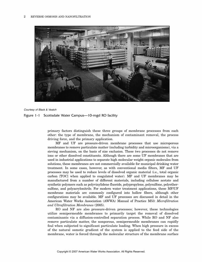
This first chapter provides a general introduction to the reverse osmosis (RO) andnanofiltration (NF) membrane treatment processes. The subjects addressed in thischapter should serve as the basic foundation for a broader understanding of RO andNF processes as applied to potable water, industrial process water, tertiarywastewater, and reclaimed water treatment, and include a general overview of thetechnology (i.e., types of processes, history of development, general RO/NF systemdescription, and typical performance), specific applications, and membrane materialsand configurations. Successive chapters will build on these concepts to provide moredetailed information about process design (chapter 2), facility design and construc-tion (chapter 3), and operations and maintenance (O&M) (chapter 4). For readersunfamiliar with RO and NF, a typical facility is shown in Figure 1-1. This pictureshows the 10-mgd Scottsdale Water Campus, an RO system treating reclaimed waterfor aquifer recharge. The RO process itself consists of numerous skids with longhorizontal pressure vessels containing the membrane elements, as shown in thecenter of the picture. The prefiltration (i.e., cartridge filters) to remove particulatematter upstream of the RO process is shown in the foreground at the bottom of thepicture, and the high pressure pumps are aligned along the left side.
OVERVIEW _______________________________________________This section first provides a brief overview of the different types of membraneprocesses. The discussion subsequently narrows to RO and NF processes—the focusof this manual—presenting a brief history of the development of RO and NFmembranes and the basics of RO and NF systems.
Types of Membrane ProcessesThe five membrane processes commonly used in the production of drinking water areRO, NF, ultrafiltration (UF), microfiltration (MF), and electrodialysis/electrodialysisreversal (ED/EDR). Although all five are classified as membrane processes, thetechnologies and applications are very different in some cases. In general, there arethree groups of similar membrane processes: MF/UF, RO/NF, and ED/EDR. Four
Copyright © 2007 American Water Works Association. All Rights Reserved.
2 REVERSE OSMOSIS AND NANOFILTRATION
primary factors distinguish these three groups of membrane processes from eachother: the type of membrane, the mechanism of contaminant removal, the processdriving force, and the primary application.
MF and UF are pressure-driven membrane processes that use microporousmembranes to remove particulate matter (including turbidity and microorganisms), via asieving mechanism, on the basis of size exclusion. These two processes do not removeions or other dissolved constituents. Although there are some UF membranes that areused in industrial applications to separate high molecular weight organic molecules fromsolutions, these membranes are not commercially available for municipal drinking watertreatment. In some cases, however, as with conventional media filters, MF and UFprocesses may be used to reduce levels of dissolved organic material (i.e., total organiccarbon [TOC] when applied to coagulated water). MF and UF membranes may bemanufactured from a number of different materials, including cellulose acetate andsynthetic polymers such as polyvinylidene fluoride, polypropylene, polysulfone, polyether-sulfone, and polyacrylonitrile. For modern water treatment applications, these MF/UFmembrane materials are commonly configured into hollow fibers, although otherconfigurations may be available. MF and UF processes are discussed in detail in theAmerican Water Works Association (AWWA) Manual of Practice M53: Microfiltrationand Ultrafiltration Membranes (2005).
RO and NF are also pressure-driven processes; however, these technologiesutilize semipermeable membranes to primarily target the removal of dissolvedcontaminants via a diffusion-controlled separation process. While RO and NF alsoremove particulate matter, the nonporous, semipermeable membranes can rapidlyfoul when subjected to significant particulate loading. When high pressure in excessof the natural osmotic gradient of the system is applied to the feed side of themembrane, water is forced through the molecular structure of the membrane surface
Courtesy of Black & Veatch
Figure 1-1 Scottsdale Water Campus—10-mgd RO facility
Copyright © 2007 American Water Works Association. All Rights Reserved.
INTRODUCTION 3
while the dissolved solids (i.e., the solutes) are largely rejected. Although solutes canalso diffuse through the semipermeable membranes, the rate of mass transfer ofthese constituents is much slower than that of the water. Consequently, the waterthat passes through the membrane (i.e., the permeate) contains fewer dissolvedsolids than does water entering the system (i.e., the feed).
The amount of energy (hydraulic pressure) required to drive the feedwater acrossthe membrane depends on the membrane material and thickness, as well as the osmoticpressure of the feed. The osmotic pressure is the pressure on the membrane created bythe naturally occurring process of water flowing from a dilute solution (i.e., lowerdissolved solids concentration) across a semipermeable membrane to a more concentratedsolution (i.e., higher dissolved solids concentration). Thus, energy in the form of hydraulicpressure is required to overcome both the physical resistance of the membrane itself andthe osmotic pressure of the system. Because this pressure is applied to force wateragainst the natural osmotic gradient to produce less saline water from more concentratedwater, the treatment process is called reverse osmosis.
The first RO membranes were developed at the University of California at LosAngeles in the early 1960s by Loeb and Sourirajan, who produced a membrane togenerate drinking water from seawater (Buros 1980). This relatively thick membranewas made from cellulose acetate and required feed pressure in excess of 1,000 psi.Currently, RO membranes used to desalinate seawater require about 800 to 1,200 psi,while brackish water applications may necessitate feed pressure ranging from 100 to600 psi. For a given membrane system and operating conditions, the feed pressurerequired depends primarily on the total dissolved solids (TDS) concentration and thetemperature of the feedwater—lower TDS levels and warmer waters require lowerfeed pressure to produce similar quality and quantity of permeate.
NF membranes were developed in the late 1970s as a variant of RO membraneswith reduced rejection characteristics for smaller, less charged ions, such as sodiumand chloride. Because these membranes also required lower operating feed pressure,NF was well suited for applications such as softening and dissolved organic carbon(DOC)/disinfection by-product (DBP) precursor removal in which TDS was not aprimary concern, because treatment objectives could be achieved at lower energycosts than with RO. Common applications for hardness and DOC removal mayrequire only 70 to 120 psi using currently available NF membranes.
The two primary materials used to manufacture RO and NF membranes arecellulose acetate (and its derivatives) and various polyamides used in thin-filmcomposite membrane construction. Although both RO and NF membranes aremanufactured in several physical configurations, the spiral-wound configuration isthe only one that is widely used in municipal treatment applications. (Membranematerials and configurations are discussed in more detail later in this chapter.)
ED/EDR are electrically driven membrane processes that remove dissolved solidsusing cation- and anion-selective membranes. However, unlike RO and NF, ED/EDR doesnot provide a barrier to pathogens and does not remove suspended solids or noncharged,nonionic constituents. In RO and NF processes, product water is filtered while passingthrough the membrane. By contrast, with ED/EDR the demineralized product waterpasses along the membrane surface in a tangential pattern while charged ions aretransported through the membrane and concentrated into the brine stream; thus, theproduct water does not pass through a membrane barrier. ED/EDR has been usedprimarily to desalinate brackish waters and applied in specialty applications, such as theremoval of fluoride or radionuclides. In addition, because ED/EDR does not affect silicaconcentrations, it may be advantageous in cases in which silica removal is not needed.Additional information about ED/EDR may be found in the AWWA Manual of PracticeM38: Electrodialysis and Electrodialysis Reversal (1995).
Copyright © 2007 American Water Works Association. All Rights Reserved.
4 REVERSE OSMOSIS AND NANOFILTRATION
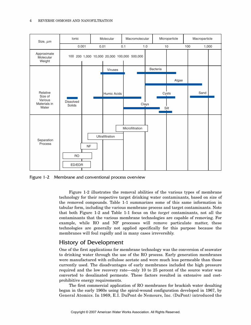
Figure 1-2 illustrates the removal abilities of the various types of membranetechnology for their respective target drinking water contaminants, based on size ofthe removed compounds. Table 1-1 summarizes some of this same information intabular form, including the various membrane process and target contaminants. Notethat both Figure 1-2 and Table 1-1 focus on the target contaminants, not all thecontaminants that the various membrane technologies are capable of removing. Forexample, while RO and NF processes will remove particulate matter, thesetechnologies are generally not applied specifically for this purpose because themembranes will foul rapidly and in many cases irreversibly.
History of DevelopmentOne of the first applications for membrane technology was the conversion of seawaterto drinking water through the use of the RO process. Early generation membraneswere manufactured with cellulose acetate and were much less permeable than thosecurrently used. The disadvantages of early membranes included the high pressurerequired and the low recovery rate—only 10 to 25 percent of the source water wasconverted to desalinated permeate. These factors resulted in extensive and cost-prohibitive energy requirements.
The first commercial application of RO membranes for brackish water desaltingbegan in the early 1960s using the spiral-wound configuration developed in 1967, byGeneral Atomics. In 1969, E.I. DuPont de Nemours, Inc. (DuPont) introduced the
Figure 1-2 Membrane and conventional process overview
Size,Ionic Molecular Macromolecular Microparticle Macroparticle
ApproximateMolecular
Weight
0.001 0.01 0.1 1.0 10 100 1,000
100 200 1,000 10,000 20,000 100,000 500,000
RelativeSize ofVarious
Materials inWater
Bacteria
DissolvedSolids
Humic Acids
Algae
Sand
SeparationProcess
Microfiltration
Ultrafiltration
NF
RO
ED/EDR
Viruses
ClaysSilt
Cysts
μm
Copyright © 2007 American Water Works Association. All Rights Reserved.
INTRODUCTION 5
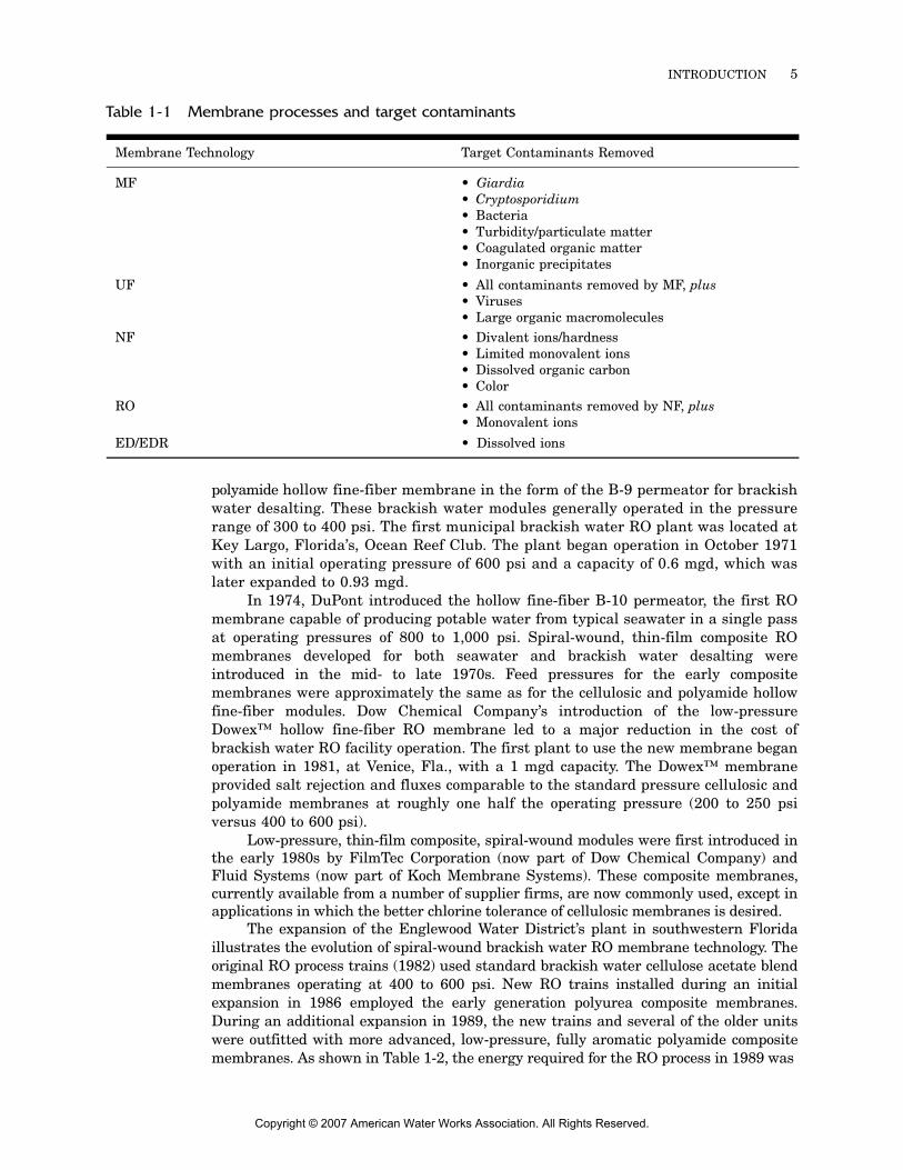
Table 1-1 Membrane processes and target contaminants
Membrane Technology Target Contaminants Removed
MF • Giardia• Cryptosporidium• Bacteria• Turbidity/particulate matter• Coagulated organic matter• Inorganic precipitates
UF • All contaminants removed by MF, plus• Viruses• Large organic macromolecules
NF • Divalent ions/hardness• Limited monovalent ions• Dissolved organic carbon• Color
RO • All contaminants removed by NF, plus• Monovalent ions
ED/EDR • Dissolved ions
polyamide hollow fine-fiber membrane in the form of the B-9 permeator for brackishwater desalting. These brackish water modules generally operated in the pressurerange of 300 to 400 psi. The first municipal brackish water RO plant was located atKey Largo, Florida’s, Ocean Reef Club. The plant began operation in October 1971with an initial operating pressure of 600 psi and a capacity of 0.6 mgd, which waslater expanded to 0.93 mgd.
In 1974, DuPont introduced the hollow fine-fiber B-10 permeator, the first ROmembrane capable of producing potable water from typical seawater in a single passat operating pressures of 800 to 1,000 psi. Spiral-wound, thin-film composite ROmembranes developed for both seawater and brackish water desalting wereintroduced in the mid- to late 1970s. Feed pressures for the early compositemembranes were approximately the same as for the cellulosic and polyamide hollowfine-fiber modules. Dow Chemical Company’s introduction of the low-pressureDowex™ hollow fine-fiber RO membrane led to a major reduction in the cost ofbrackish water RO facility operation. The first plant to use the new membrane beganoperation in 1981, at Venice, Fla., with a 1 mgd capacity. The Dowex™ membraneprovided salt rejection and fluxes comparable to the standard pressure cellulosic andpolyamide membranes at roughly one half the operating pressure (200 to 250 psiversus 400 to 600 psi).
Low-pressure, thin-film composite, spiral-wound modules were first introduced inthe early 1980s by FilmTec Corporation (now part of Dow Chemical Company) andFluid Systems (now part of Koch Membrane Systems). These composite membranes,currently available from a number of supplier firms, are now commonly used, except inapplications in which the better chlorine tolerance of cellulosic membranes is desired.
The expansion of the Englewood Water District’s plant in southwestern Floridaillustrates the evolution of spiral-wound brackish water RO membrane technology. Theoriginal RO process trains (1982) used standard brackish water cellulose acetate blendmembranes operating at 400 to 600 psi. New RO trains installed during an initialexpansion in 1986 employed the early generation polyurea composite membranes.During an additional expansion in 1989, the new trains and several of the older unitswere outfitted with more advanced, low-pressure, fully aromatic polyamide compositemembranes. As shown in Table 1-2, the energy required for the RO process in 1989 was
Copyright © 2007 American Water Works Association. All Rights Reserved.
6 REVERSE OSMOSIS AND NANOFILTRATION
50 percent less than the original 1982 plant design, a dramatic decrease made possibleby rapid advances in the technology in less than a decade. Train F, installed in 2005,uses even less energy. Currently, all trains use polyamide composite RO membranesin a single-stage arrangement with energy recovery turbopumps that recover energyfrom the waste concentrate stream and transfer it to the feed. Chapter 3 discussesintegrated turbopumps and other commercially available energy recovery devices.
The concept of membrane softening was introduced in 1976, and the followingyear a 0.25-mgd membrane softening plant was installed in Pelican Bay, Naples, Fla.The plant used a Fluid Systems hydrolyzed (i.e., “loose”) RO membrane and was laterexpanded to 0.5 mgd. Membrane softening was in limited use until 1984, whenFilmTec Corporation introduced polyamide NF spiral-wound elements. Other manu-facturers subsequently developed similar products.
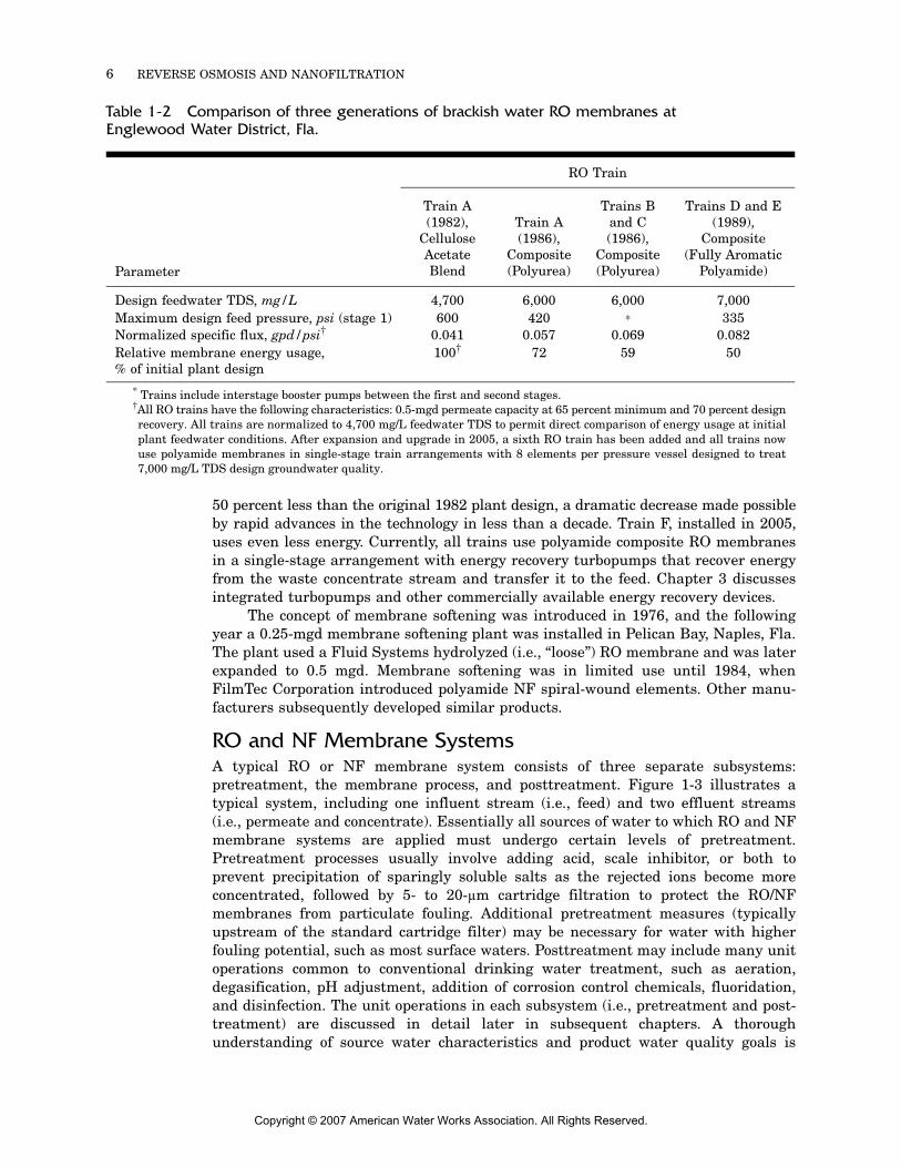
RO and NF Membrane SystemsA typical RO or NF membrane system consists of three separate subsystems:pretreatment, the membrane process, and posttreatment. Figure 1-3 illustrates atypical system, including one influent stream (i.e., feed) and two effluent streams(i.e., permeate and concentrate). Essentially all sources of water to which RO and NFmembrane systems are applied must undergo certain levels of pretreatment.Pretreatment processes usually involve adding acid, scale inhibitor, or both toprevent precipitation of sparingly soluble salts as the rejected ions become moreconcentrated, followed by 5- to 20-µm cartridge filtration to protect the RO/NFmembranes from particulate fouling. Additional pretreatment measures (typicallyupstream of the standard cartridge filter) may be necessary for water with higherfouling potential, such as most surface waters. Posttreatment may include many unitoperations common to conventional drinking water treatment, such as aeration,degasification, pH adjustment, addition of corrosion control chemicals, fluoridation,and disinfection. The unit operations in each subsystem (i.e., pretreatment and post-treatment) are discussed in detail later in subsequent chapters. A thoroughunderstanding of source water characteristics and product water quality goals is
Table 1-2 Comparison of three generations of brackish water RO membranes at Englewood Water District, Fla.
RO Train
Train A (1982),
Cellulose Acetate Blend
Train A (1986),
Composite (Polyurea)
Trains B and C (1986),
Composite (Polyurea)
Trains D and E (1989),
Composite (Fully Aromatic
Polyamide)Parameter
Design feedwater TDS, mg/L 4,700 6,000 6,000 7,000Maximum design feed pressure, psi (stage 1) 600 420 * 335Normalized specific flux, gpd/psi† 0.041 0.057 0.069 0.082Relative membrane energy usage, % of initial plant design
100† 72 59 50
* Trains include interstage booster pumps between the first and second stages.†All RO trains have the following characteristics: 0.5-mgd permeate capacity at 65 percent minimum and 70 percent designrecovery. All trains are normalized to 4,700 mg/L feedwater TDS to permit direct comparison of energy usage at initialplant feedwater conditions. After expansion and upgrade in 2005, a sixth RO train has been added and all trains nowuse polyamide membranes in single-stage train arrangements with 8 elements per pressure vessel designed to treat7,000 mg/L TDS design groundwater quality.
Copyright © 2007 American Water Works Association. All Rights Reserved.
INTRODUCTION 7
essential to the successful design and operation of a RO or NF treatment plant,because the contaminants found in the source water determine which combination ofpre- and posttreatment methods will be necessary.
RO AND NF MEMBRANE APPLICATIONS ___________________This section describes the major current applications of RO and NF membraneprocesses, including: desalting, the removal/reduction of DBP precursors, hardness(i.e., softening), color, inorganic contaminants (e.g., nitrate, fluoride, arsenic, heavymetals, radionuclides, etc.), synthetic and volatile organic compounds, pathogens, andindirect potable reuse. A short discussion of emerging applications is also provided.Note that RO and NF can also remove suspended solids/particulate matter; however,because the semipermeable membranes are not porous (and therefore not able to bebackwashed), any significant particulate loading can rapidly and sometimes irrevers-ibly foul the membranes. Thus, although RO and NF will reduce particulate matterlevels (i.e., turbidity, particle counts, etc.), the technology is not applied specificallyfor this purpose, and pretreatment to remove particulate matter upstream of themembranes is almost always employed.
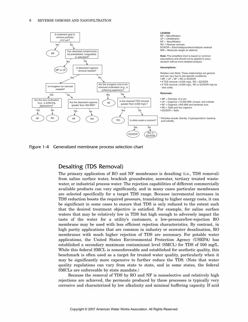
A flowchart for selecting an appropriate membrane process (including MF, UF,and ED/EDR) is shown in Figure 1-4. Note that this is a very general guideline anddoes not take into account cost, site-, or application-specific considerations. Thefigure is primarily intended to serve as an illustrative tool to distinguish the varioustypes of membrane processes on the basis of treatment application.
Figure 1-3 Typical RO or NF membrane system
ACID SCALE
INHIBITOR DISINFECTANT
STABILIZING CHEMICALS
Distribution System
Concentrate
Decarbonation or
Degasification
Membrane Array
Cartridge Filtration
Pretreatment Membrane Process Posttreatment
Source Water
Copyright © 2007 American Water Works Association. All Rights Reserved.
8 REVERSE OSMOSIS AND NANOFILTRATION
Desalting (TDS Removal)The primary application of RO and NF membranes is desalting (i.e., TDS removal)from saline surface water, brackish groundwater, seawater, tertiary treated waste-water, or industrial process water. The rejection capabilities of different commerciallyavailable products can vary significantly, and in many cases particular membranesare selected specifically for a target TDS range. Because incremental increases inTDS reduction boosts the required pressure, translating to higher energy costs, it canbe significant in some cases to ensure that TDS is only reduced to the extent suchthat the desired treatment objective is satisfied. For example, for saline surfacewaters that may be relatively low in TDS but high enough to adversely impact thetaste of the water for a utility’s customers, a low-pressure/low-rejection ROmembrane may be used with less efficient rejection characteristics. By contrast, inhigh purity applications that are common in industry or seawater desalination, ROmembranes with much higher rejection of TDS are necessary. For potable waterapplications, the United States Environmental Protection Agency (USEPA) hasestablished a secondary maximum contaminant level (SMCL) for TDS of 500 mg/L.While this federal SMCL is nonenforceable and established for aesthetic quality, thisbenchmark is often used as a target for treated water quality, particularly when itmay be significantly more expensive to further reduce the TDS. (Note that waterquality regulations can vary from state to state, and in some states, the federalSMCLs are enforceable by state mandate.)
Because the removal of TDS by RO and NF is nonselective and relatively highrejections are achieved, the permeate produced by these processes is typically verycorrosive and characterized by low alkalinity and minimal buffering capacity. If acid
Figure 1-4 Generalized membrane process selection chart
Is treatment goal toremove particles
>0.2 μm?
MFCan dissolved contaminantsbe precipitated, coagulated,
or adsorbed?
MF or UFIs dissolved organics
removal needed?
Are the inorganic ions to beremoved multivalent (e.g., a
softening appliction)?
NF
Is inorganic ion removalneeded?
Is the required TDS removalgreater than 3,000 mg/L?
Is silica scale a concern?RO
ED/EDR RO orED/EDR
Are the dissolved organicsgreater than 400 MW?
NF RO
Are the ions multivalent(e.g., a softening
application)?
RONF
No
No
No
No
No
No
No
NoNo
Yes
Yes
Yes
Yes
Yes Yes
Yes
Yes
Yes
LEGENDMF = MicrofiltrationUF = UltrafiltrationNF = NanofiltrationRO = Reverse osmosisED/EDR = Electrodialysis/electrodialysis reversalMW = Molecular weight (in daltons)
Note: This simplified chart is based on common assumptions and should not be applied to every situation without more detailed analysis.
Assumptions:
Relative cost (Note: These relationships are generaland can vary due to site-specific conditions)• MF < UF < NF < RO or ED/EDR• If TDS removal >3,000 mg/L, RO < ED/EDR• If TDS removal <3,000 mg/L, RO or ED/EDR may be less costly
Removals:
• MF = Particles >0.2 µm• UF = Organics >10,000 MW, viruses, and colloids• NF = Organics >400 MW and hardness ions• RO = Salts and low organics• ED/EDR = Salts
* Particles include Giardia, Cryptosporidium, bacteria, and turbidity.
Copyright © 2007 American Water Works Association. All Rights Reserved.
INTRODUCTION 9
is used as pretreatment to control scaling, the pH may also be low, furthercompounding the aggressive nature of the permeate. However, RO and NF systemscan be designed with appropriate posttreatment processes to produce water that isboth low in TDS and well buffered with sufficient alkalinity to help reduce thepotential for pipe corrosion in the distribution system.
DBP PrecursorsBecause DBPs are a significant regulatory concern, RO and NF membranes areincreasingly applied to remove DBP precursors such as natural organic matter(NOM)/TOC, which can react with various disinfectants used in the water treatmentprocess to form potential carcinogens. These DBPs include total trihalomethanes(TTHMs) and the sum of five haloacetic acids (HAA5), both of which are strictlyregulated in the parts per billion range by the Stage 1 and Stage 2 Disinfectants andDisinfection Byproducts Rules. As a result of these low maximum contaminant levels(MCLs), NOM removal is a significant water treatment objective for many utilities.RO or NF as a stand-alone process has been shown in many cases to reduce TOC toless than 0.5 mg/L. RO can also remove TTHMs and HAAs, albeit less efficiently thantheir precursor material; however, it is uncommon to apply these membranes for DBPreduction after the disinfection process in water treatment plants as a result of thesusceptibility of most such membranes to damage from chemical disinfectants.
HardnessNF has become a significant alternative to lime softening for reducing the level ofcalcium and magnesium ions in naturally hard waters where TDS reduction is not aprimary treatment goal. Although RO membranes are also capable of reducinghardness, NF membranes have lower rejection characteristics for monovalent ions,allowing them to be operated at lower pressures while still efficiently removing thedivalent ions that contribute to hardness, resulting in energy cost savings. Typically,NF membranes used for softening applications remove more than 95 percent of totalhardness.
ColorNF is also more effective than lime softening in removing naturally occurring colorand DBP precursors, both comprised primarily of organic carbon, and can often beoperated more efficiently than RO. NF is generally capable of removing more than95 percent of color.
Inorganic ContaminantsThe USEPA currently recognizes RO as the best available technology (BAT) forremoving most inorganic compounds (IOCs) regulated under the Safe Drinking WaterAct (SDWA) (Clark and Parrotta 1991), including radionuclides and arsenic, amongmany others. This classification reflects the broad-spectrum removal capability of theRO process. The ability of NF to remove IOCs is determined to a large extent by thespecific dissolved solids character of the water. NF rejection of specific multivalentcations is a function of solution pH and the speciation of other ionic constituentspresent to a greater degree than for the RO process.
One of the more common applications of RO for treating a specific inorganiccontaminant is nitrate removal. RO is considered an effective nitrate removal processfor groundwater supplies polluted by the agricultural use of nitrate-containingfertilizers or septic tank discharges. Rejection of nitrate by some RO membranes issignificant; composite polyamide low-pressure brackish water membranes typically
Copyright © 2007 American Water Works Association. All Rights Reserved.
10 REVERSE OSMOSIS AND NANOFILTRATION
exhibit sodium nitrate rejection in the range of 93 to 97 percent (FilmTec 1988; Toray1989). Several RO plants are currently in operation in southern California treatinggroundwater contaminated with high concentrations of nitrate from past agriculturalpractices, including those in the cities of Riverside and Tustin, as well as severalfacilities operated by the Chino Basin Desalter Authority. Note that NF is generallynot applied for nitrate removal as a result of its relatively low rejection of this anioncompared to RO.
Another inorganic contaminant to which RO is often applied is fluoride. Manygroundwater sources in the United States contain elevated levels of naturallyoccurring fluoride. The USEPA has established a fluoride MCL of 4 mg/L to protectagainst skeletal fluorosis and a recommended SMCL of 2 mg/L to prevent toothdiscoloration. Because levels of naturally occurring fluoride are about the same orderof magnitude as the MCL, it is generally not necessary to achieve extremely highrejection, particularly considering that 0.8 to 1.2 mg/L of fluoride in drinking wateris recommended for dental health. As a result, in many cases treatment costs can bereduced through the use of split treatment, in which a portion of adequately treatedsource water is bypassed around the membrane system and blended with the ROpermeate.
In general, for water quality constituents or specific inorganic contaminantsthat are relatively common, RO/NF membrane manufacturers have modelingsoftware that can predict permeate quality fairly accurately. However, for theremoval of less common inorganic contaminants for which RO and NF have not beenas frequently utilized, rejections are typically based on manufacturer, utility, orindependent, third party experience and research. Although increasingly uncommonfor many well-known inorganic contaminants, pilot testing can be conducted toquantify or verify rejection levels, if desired.
Synthetic and Volatile Organic ChemicalsMany of the synthetic organic compounds (SOCs) regulated by the USEPA indrinking water supplies are pesticide residuals. Pilot testing has been conducted in amunicipality–USEPA partnership to evaluate the pesticide removal efficiency of anumber of different types of RO membranes for treatment of groundwatercontaminated by various agricultural chemicals (Bailer et al. 1987). This study foundthat removals were greatest for the polyamide thin-film composite membranes (67 to95 percent), and it concluded that RO should be considered as a water treatmentprocess for this application (Lykins et al. 1988). Other studies have assessed thecapability of a wide range of NF membranes to remove commonly occurringpesticides to below the 0.1 µg/L (Côté et al. 1993; Hofman et al. 1993). Theoretically,specific SOC rejection is primarily a function of molecular size and degree ofionization. This theory was corroborated by a pilot study demonstrating that thedegree of rejection is proportional to the molecular weight. Synthetic organicchemicals with a molecular weight greater than 300 Daltons were completely rejectedby one type of NF membrane, while those with molecular weights less than 300 Daltonswere only partially rejected. For these studies, the degree of rejection wasproportional to the molecular weight (Taylor et al. 1989b).
It is less common for RO and NF to be applied for the removal of volatile organiccompounds (VOCs), such as trichloroethylene and tetrachloroethylene, among others,because rejection is generally inefficient (albeit varying by specific compound). Inaddition, many VOCs are solvents that at higher concentrations may dissolve theglue lines on the membrane elements or damage the membranes themselves. It hasalso been reported that some VOCs may adsorb onto the membrane, potentially
Copyright © 2007 American Water Works Association. All Rights Reserved.
INTRODUCTION 11
reducing permeability or desorbing into the permeate in concentrations higher thanthe feed until steady state is achieved (Lenz et al. 2005).
PathogensBecause semipermeable RO and NF membranes are not porous, they have the abilityto screen microorganisms and particulate matter in the feedwater. This ability hasbeen verified in a number of studies, such as one that demonstrated that ROmembranes provide between 4- and 5-log (i.e., 99.99 to 99.999 percent) removal ofviruses normally associated with waterborne disease (Lozier et al. 1994). Accordingto the Guidance Manual for Compliance with the Filtration and DisinfectionRequirements for Public Water Systems Using Surface Water Sources (commonlyreferenced as the Surface Water Treatment Rule [SWTR] Guidance Manual), RO islisted as an alternate filtration technology that is effective for the removal of Giardiaand viruses (USEPA 1990), such that unlike many other alternate technologies, nopiloting or other studies are necessary to demonstrate that the RO process canachieve 3.0-log (i.e., 99.9 percent) Giardia and 4.0-log virus removal when combinedwith disinfection. The proposed Ground Water Rule also notes the demonstratedability of RO and NF to achieve 4.0-log virus removal. In addition, under the LongTerm 2 Enhanced Surface Water Treatment Rule, both NF and RO are specificallylisted as membrane filtration technologies that can be applied to achieve significantCryptosporidium removal credit (USEPA 2006).
However, it is important to note that RO and NF are not necessarily absolutebarriers. RO and NF membranes are primarily designed for the removal of TDSrather than particulate matter, and thus the elimination of all small seal leaks thathave only a nominal impact on the salt rejection characteristics is not the primaryfocus of the manufacturing process. Consequently, RO and NF spiral-wound elementsare not intended to be sterilizing membranes and some passage of particulate matter,including pathogens, may occur despite the absence of pores in the membrane.
Indirect Potable ReuseBoth RO and NF are being increasingly used in the reclamation of municipalwastewaters serving indirectly as future potable water supplies and other reuseapplications. In some of these applications, RO and NF remove many contaminants,including nitrogen, heavy metals, TOC, and pathogens, and subsequently the high-quality permeate is injected into groundwater aquifers for recharge. The under-ground strata serve as an additional filtration step to achieve natural attenuation ofthe groundwater supply, in some cases over many years, before it is pumped to thesurface again for further treatment and distribution. RO technology is often a criticalcomponent for groundwater recharge with reclaimed water. The state of California,for example, currently requires all recycled water to be treated via RO prior toinjection. The oldest and most widely known groundwater recharge project is theOrange County Water District’s Ground Water Replenishment System in FountainValley, Calif., which originated as Water Factory 21, and has been in service since1976. Numerous other utilities in California, Arizona, and other states are alsopracticing, planning, or studying indirect potable reuse using RO.
Emerging ApplicationsBecause RO and NF achieve significant rejection/removal of a wide assortment ofpotable water contaminants, these processes are often among the first treatmenttechnologies considered for a variety of emerging applications. For example,perchlorate—an inorganic anion—is one such emerging contaminant that is only
Copyright © 2007 American Water Works Association. All Rights Reserved.
12 REVERSE OSMOSIS AND NANOFILTRATION
effectively removed by a limited range of technologies, such as RO and ion exchange.RO and NF are also likely be among the BATs for removing contaminants such asendocrine disruptors and pharmaceutically active compounds, two broad classes ofcontaminants that are just beginning to be studied and quantified in drinking watersources. As improved analytical techniques continue to reveal previously unknowncontaminants, it is likely that the number of applications for RO and NF will likewiseincrease.
MEMBRANE MATERIALS AND CONFIGURATIONS ____________The fundamental components of an RO/NF system are the membrane material andthe configuration into which the material is manufactured. This section describesboth of these components, elaborating on the different types of materials andconfigurations used in drinking water applications.
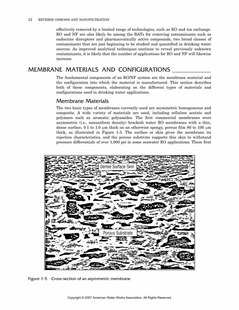
Membrane MaterialsThe two basic types of membranes currently used are asymmetric homogeneous andcomposite. A wide variety of materials are used, including cellulose acetate andpolymers such as aromatic polyamides. The first commercial membranes wereasymmetric (i.e., nonuniform density) brackish water RO membranes with a thin,dense surface, 0.1 to 1.0 µm thick on an otherwise spongy, porous film 80 to 100 µmthick, as illustrated in Figure 1-5. The surface or skin gives the membrane itsrejection characteristics, and the porous substrate supports this skin to withstandpressure differentials of over 1,000 psi in some seawater RO applications. These first
Figure 1-5 Cross-section of an asymmetric membrane
Copyright © 2007 American Water Works Association. All Rights Reserved.
INTRODUCTION 13
commercial asymmetric RO membranes were made of cellulose acetate material, withthe dense skin obtained through an annealing process. Modified cellulosic mem-branes, including cellulose diacetate and cellulose triaetate, are less expensive thannoncellulosic membranes and are thus still used in some applications.
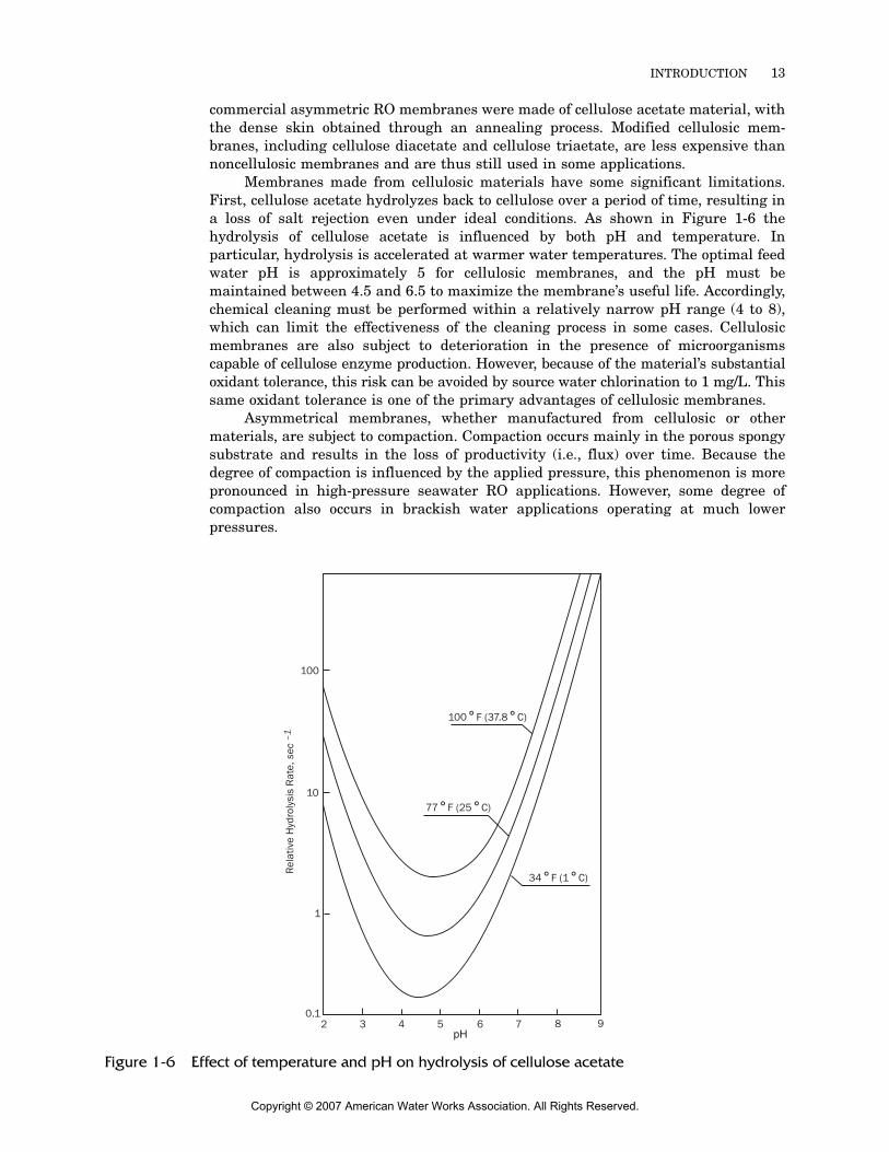
Membranes made from cellulosic materials have some significant limitations.First, cellulose acetate hydrolyzes back to cellulose over a period of time, resulting ina loss of salt rejection even under ideal conditions. As shown in Figure 1-6 thehydrolysis of cellulose acetate is influenced by both pH and temperature. Inparticular, hydrolysis is accelerated at warmer water temperatures. The optimal feedwater pH is approximately 5 for cellulosic membranes, and the pH must bemaintained between 4.5 and 6.5 to maximize the membrane’s useful life. Accordingly,chemical cleaning must be performed within a relatively narrow pH range (4 to 8),which can limit the effectiveness of the cleaning process in some cases. Cellulosicmembranes are also subject to deterioration in the presence of microorganismscapable of cellulose enzyme production. However, because of the material’s substantialoxidant tolerance, this risk can be avoided by source water chlorination to 1 mg/L. Thissame oxidant tolerance is one of the primary advantages of cellulosic membranes.
Asymmetrical membranes, whether manufactured from cellulosic or othermaterials, are subject to compaction. Compaction occurs mainly in the porous spongysubstrate and results in the loss of productivity (i.e., flux) over time. Because thedegree of compaction is influenced by the applied pressure, this phenomenon is morepronounced in high-pressure seawater RO applications. However, some degree ofcompaction also occurs in brackish water applications operating at much lowerpressures.
Figure 1-6 Effect of temperature and pH on hydrolysis of cellulose acetate
2 3 4 5 6 7 8 90.1
1
10
100
100°F (37.8°C)
77°F (25°C)
34°F (1°C)
Rel
ativ
e H
ydro
lysi
s R
ate,
sec
–1
pH
Copyright © 2007 American Water Works Association. All Rights Reserved.
14 REVERSE OSMOSIS AND NANOFILTRATION
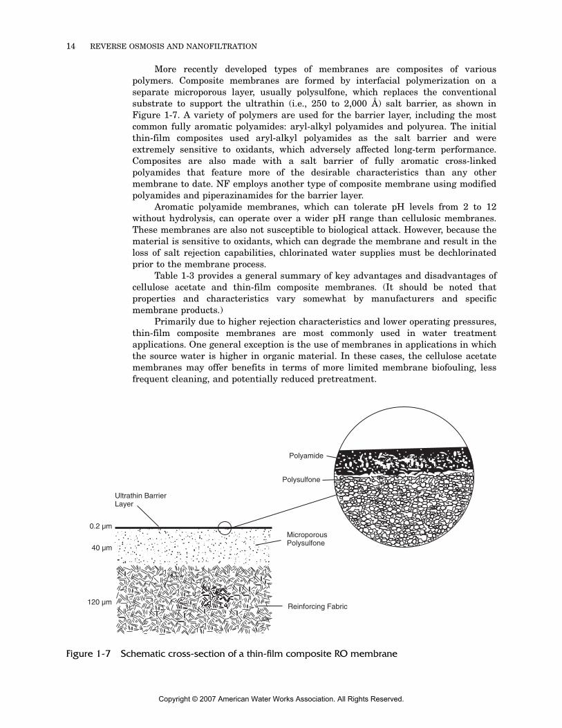
More recently developed types of membranes are composites of variouspolymers. Composite membranes are formed by interfacial polymerization on aseparate microporous layer, usually polysulfone, which replaces the conventionalsubstrate to support the ultrathin (i.e., 250 to 2,000 Å) salt barrier, as shown inFigure 1-7. A variety of polymers are used for the barrier layer, including the mostcommon fully aromatic polyamides: aryl-alkyl polyamides and polyurea. The initialthin-film composites used aryl-alkyl polyamides as the salt barrier and wereextremely sensitive to oxidants, which adversely affected long-term performance.Composites are also made with a salt barrier of fully aromatic cross-linkedpolyamides that feature more of the desirable characteristics than any othermembrane to date. NF employs another type of composite membrane using modifiedpolyamides and piperazinamides for the barrier layer.
Aromatic polyamide membranes, which can tolerate pH levels from 2 to 12without hydrolysis, can operate over a wider pH range than cellulosic membranes.These membranes are also not susceptible to biological attack. However, because thematerial is sensitive to oxidants, which can degrade the membrane and result in theloss of salt rejection capabilities, chlorinated water supplies must be dechlorinatedprior to the membrane process.
Table 1-3 provides a general summary of key advantages and disadvantages ofcellulose acetate and thin-film composite membranes. (It should be noted thatproperties and characteristics vary somewhat by manufacturers and specificmembrane products.)
Primarily due to higher rejection characteristics and lower operating pressures,thin-film composite membranes are most commonly used in water treatmentapplications. One general exception is the use of membranes in applications in whichthe source water is higher in organic material. In these cases, the cellulose acetatemembranes may offer benefits in terms of more limited membrane biofouling, lessfrequent cleaning, and potentially reduced pretreatment.
Figure 1-7 Schematic cross-section of a thin-film composite RO membrane
Ultrathin BarrierLayer
Polyamide
Polysulfone
MicroporousPolysulfone
Reinforcing Fabric
0.2 µm
40 µm
120 µm
Copyright © 2007 American Water Works Association. All Rights Reserved.
INTRODUCTION 15
Membrane Element ConfigurationsA membrane by itself is fragile and must be carefully supported and packaged so thatit can be integrated into a unit process. In addition, features are added that enhancepermeation of water through the membrane (i.e., flux) and which increase saltrejection. The membrane is generally packaged to minimize hydraulic pressure lossesand yet allow sufficient velocities to keep the surface of the membrane flushed clean ofconcentrated salts and particulate matter. The mechanical design of a membraneelement also allows for passage of colloidal and particulate matter through to theconcentrate to the extent possible in order to minimize particulate fouling. All of thesefeatures are combined with the membrane material itself into a membrane element,which is the smallest discrete unit of an RO or NF system. There are four basicelement configurations that have been utilized to at least some extent in commercialapplications: tubular, plate-and-frame, hollow fine-fiber, and spiral-wound. Althougheach of these configurations is described briefly as follows, only the spiral-woundconfiguration is widely used in modern municipal water treatment applications.
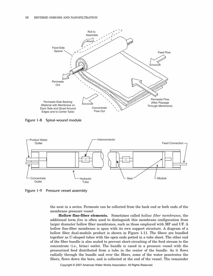
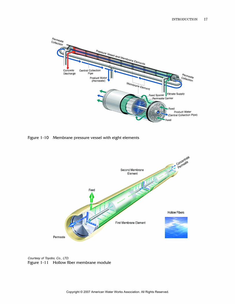
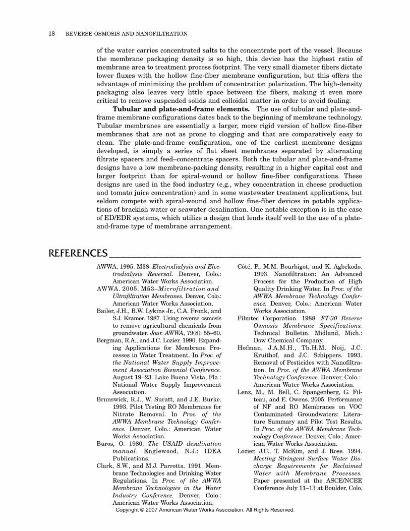
Spiral-wound elements. A membrane utilized in a spiral-wound configura-tion, as illustrated in Figure 1-8, is manufactured or cast in sheet form on a backingmaterial such as sail cloth (for cellulosic membranes) or a nonwoven polyester web(for the newer composite membranes). Two of these sheets are placed back to back,separated by a spacing fabric/screen that acts as a permeate channel or carrier. Twosides and one end of this sandwich assembly are glued together along the edges toform an envelope or leaf. The open end of the leaf is connected to the permeate tube,around which the leaf is wrapped to form the spiral. An additional sheet of plasticnetting (i.e., the feed spacer) is wrapped with each of the numerous leaves to separatethe membrane surfaces, maintain the feed channel height, and create turbulence.The spiral assembly, or element, is secured to prevent unraveling by an outer wrap,and a concentrate (i.e., brine) seal is fixed to one end. An antitelescoping device isattached to both ends of the membrane element to maintain a fixed space betweenelements and facilitate flow from one element to the next. Multiple elements arehoused in a series in a cylindrical vessel, as illustrated in Figures 1-9 and 1-10, withthe feed and concentrate flowing through the feed-side channels in a straight linealong the axis of the element. Some of the water penetrates the membrane andspirals its way to the center, collecting in the central permeate tube. The remainingwater passes from the element and out the concentrate port of the pressure vessel.For most applications, several elements, usually six to eight, are housed in a serieswithin the pressure vessel. .The concentrate from one element serves as the feed for
Table 1-3 Comparison of thin-film composite and cellulose acetate membranes
ParameterThin-Film CompositePolymer Membranes
Cellulose Acetate Membranes
Salt rejection Higher (>99.5%) Lower (up to 95%)Net driving pressure Lower HigherSurface charge More negative Less negativeChlorine tolerance Poor FairCleaning frequency Higher LowerOrganics removal Higher LowerBiofouling More susceptible Less susceptibleBiodegradation None HigherpH tolerance High (2–13) Limited (4–8)
Copyright © 2007 American Water Works Association. All Rights Reserved.
16 REVERSE OSMOSIS AND NANOFILTRATION
the next in a series. Permeate can be collected from the back end or both ends of themembrane pressure vessel
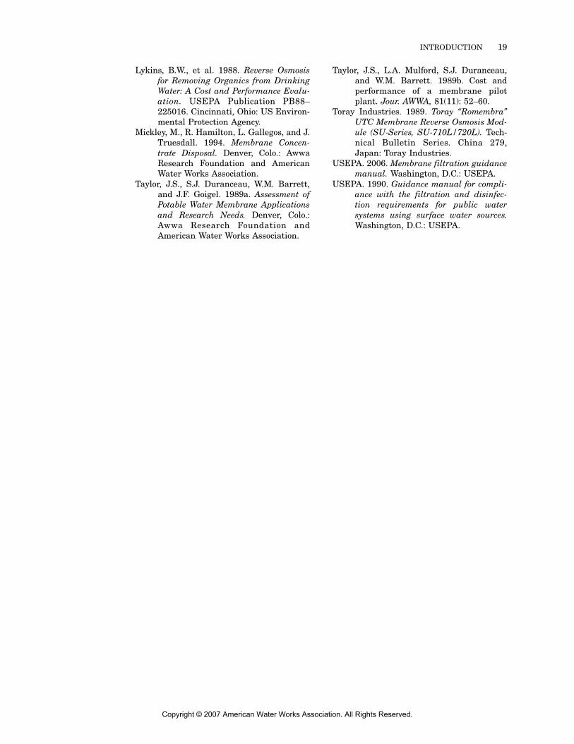
Hollow fine-fiber elements. Sometimes called hollow fiber membranes, theadditional term fine is often used to distinguish this membrane configuration fromlarger diameter hollow fiber membranes, such as those employed with MF and UF. Ahollow fine-fiber membrane is spun with its own support structure. A diagram of ahollow fiber dual-module product is shown in Figure 1-11. The fibers are bundledtogether as U-shaped tubes with the open ends potted in a tube sheet. The other endof the fiber bundle is also sealed to prevent short-circuiting of the feed stream to theconcentrate (i.e., brine) outlet. The bundle is cased in a pressure vessel with thepressurized feed distributed from a tube in the center of the bundle. As it flowsradially through the bundle and over the fibers, some of the water penetrates thefibers, flows down the bore, and is collected at the end of the vessel. The remainder
Figure 1-8 Spiral-wound module
Figure 1-9 Pressure vessel assembly
Feed-SideSpacer
Permeate-Side Backing(Material with Membrane on
Each Side and Glued AroundEdges and to Center Tube)
PermeateOut
Permeate Flow(After Passage
Through Membrane)
Feed Flow
ConcentrateFlow Out
Roll to Assemble
Product WaterOutlet
InterconnectorFeed Connection
ModuleSealHydraulicTube
ConcentrateOutlet
Copyright © 2007 American Water Works Association. All Rights Reserved.
INTRODUCTION 17
Figure 1-10 Membrane pressure vessel with eight elements
Courtesy of Toyobo, Co., LTD.
Figure 1-11 Hollow fiber membrane module
Copyright © 2007 American Water Works Association. All Rights Reserved.
18 REVERSE OSMOSIS AND NANOFILTRATION
of the water carries concentrated salts to the concentrate port of the vessel. Becausethe membrane packaging density is so high, this device has the highest ratio ofmembrane area to treatment process footprint. The very small diameter fibers dictatelower fluxes with the hollow fine-fiber membrane configuration, but this offers theadvantage of minimizing the problem of concentration polarization. The high-densitypackaging also leaves very little space between the fibers, making it even morecritical to remove suspended solids and colloidal matter in order to avoid fouling.
Tubular and plate-and-frame elements. The use of tubular and plate-and-frame membrane configurations dates back to the beginning of membrane technology.Tubular membranes are essentially a larger, more rigid version of hollow fine-fibermembranes that are not as prone to clogging and that are comparatively easy toclean. The plate-and-frame configuration, one of the earliest membrane designsdeveloped, is simply a series of flat sheet membranes separated by alternatingfiltrate spacers and feed–concentrate spacers. Both the tubular and plate-and-framedesigns have a low membrane-packing density, resulting in a higher capital cost andlarger footprint than for spiral-wound or hollow fine-fiber configurations. Thesedesigns are used in the food industry (e.g., whey concentration in cheese productionand tomato juice concentration) and in some wastewater treatment applications, butseldom compete with spiral-wound and hollow fine-fiber devices in potable applica-tions of brackish water or seawater desalination. One notable exception is in the caseof ED/EDR systems, which utilize a design that lends itself well to the use of a plate-and-frame type of membrane arrangement.
REFERENCES ______________________________________________AWWA. 1995. M38–Electrodialysis and Elec-
trodialysis Reversal. Denver, Colo.:American Water Works Association.
AWWA. 2005. M53–Microfiltration and Ultrafiltration Membranes. Denver, Colo.:American Water Works Association.
Bailer, J.H., B.W. Lykins Jr., C.A. Fronk, andS.J. Kramer. 1987. Using reverse osmosisto remove agricultural chemicals fromgroundwater. Jour. AWWA, 79(8): 55–60.
Bergman, R.A., and J.C. Lozier. 1990. Expand-ing Applications for Membrane Pro-cesses in Water Treatment. In Proc. ofthe National Water Supply Improve-ment Association Biennial Conference.August 19–23. Lake Buena Vista, Fla.:National Water Supply ImprovementAssociation.
Brunswick, R.J., W. Suratt, and J.E. Burke.1993. Pilot Testing RO Membranes forNitrate Removal. In Proc. of theAWWA Membrane Technology Confer-ence. Denver, Colo.: American WaterWorks Association.
Buros, O. 1980. The USAID desalinationmanual. Englewood, N.J.: IDEAPublications.
Clark, S.W., and M.J. Parrotta. 1991. Mem-brane Technologies and Drinking WaterRegulations. In Proc. of the AWWAMembrane Technologies in the WaterIndustry Conference. Denver, Colo.:American Water Works Association.
Côté, P., M.M. Bourbigot, and K. Agbekodo.1993. Nanofiltration: An AdvancedProcess for the Production of HighQuality Drinking Water. In Proc. of theAWWA Membrane Technology Confer-ence. Denver, Colo.: American WaterWorks Association.
Filmtec Corporation. 1988. FT-30 ReverseOsmosis Membrane Specifications.Technical Bulletin. Midland, Mich.:Dow Chemical Company.
Hofman, J.A.M.H., Th.H.M. Noij, J.C.Kruithof, and J.C. Schippers. 1993.Removal of Pesticides with Nanofiltra-tion. In Proc. of the AWWA MembraneTechnology Conference. Denver, Colo.: American Water Works Association.
Lenz, M., M. Bell, C. Spangenberg, G. Fil-teau, and E. Owens. 2005. Performanceof NF and RO Membranes on VOCContaminated Groundwaters: Litera-ture Summary and Pilot Test Results.In Proc. of the AWWA Membrane Tech-nology Conference. Denver, Colo.: Amer-ican Water Works Association.
Lozier, J.C., T. McKim, and J. Rose. 1994.Meeting Stringent Surface Water Dis-charge Requirements for ReclaimedWater with Membrane Processes.Paper presented at the ASCE/NCEEConference July 11–13 at Boulder, Colo.
Copyright © 2007 American Water Works Association. All Rights Reserved.
INTRODUCTION 19
Lykins, B.W., et al. 1988. Reverse Osmosisfor Removing Organics from DrinkingWater: A Cost and Performance Evalu-ation. USEPA Publication PB88–225016. Cincinnati, Ohio: US Environ-mental Protection Agency.
Mickley, M., R. Hamilton, L. Gallegos, and J.Truesdall. 1994. Membrane Concen-trate Disposal. Denver, Colo.: AwwaResearch Foundation and AmericanWater Works Association.
Taylor, J.S., S.J. Duranceau, W.M. Barrett,and J.F. Goigel. 1989a. Assessment ofPotable Water Membrane Applicationsand Research Needs. Denver, Colo.:Awwa Research Foundation andAmerican Water Works Association.
Taylor, J.S., L.A. Mulford, S.J. Duranceau,and W.M. Barrett. 1989b. Cost andperformance of a membrane pilotplant. Jour. AWWA, 81(11): 52–60.
Toray Industries. 1989. Toray “Romembra”UTC Membrane Reverse Osmosis Mod-ule (SU-Series, SU-710L/720L). Tech-nical Bulletin Series. China 279,Japan: Toray Industries.
USEPA. 2006. Membrane filtration guidancemanual. Washington, D.C.: USEPA.
USEPA. 1990. Guidance manual for compli-ance with the filtration and disinfec-tion requirements for public watersystems using surface water sources.Washington, D.C.: USEPA.
Copyright © 2007 American Water Works Association. All Rights Reserved.


![Preparation of hydrophilic nanofiltration membranes for …...ing nanofiltration (NF) and reverse osmosis (RO) membranes [6, 7]. Membrane fouling reduces membrane performance, increases](https://img.pdfslide.us/doc/110x75/611b4ef3f07ac85c23709bed/preparation-of-hydrophilic-nanofiltration-membranes-for-ing-nanofiltration-nf.jpg)