Embed Size (px)
Citation preview

PART# 146245 Rev. 4 (1/9/14) SJC
- 1 -
Superwall ™ Series ASSEMBLY & INSTALLATION MANUAL
Note: This manual should only be used for reference. Review the project drawings for specific
part numbers and instructions. The project drawings may supersede this manual.
7800 Internat ional Drive
Wausau, WI 54401
Telephone: (715) 845-2161Fax: (715) 843-4350
www.wausauwindow .com

PART# 146245 Rev. 4 (1/9/14) SJC
- 2 -
INDEX
Frame Extrusions ………………………………………………………….. 3
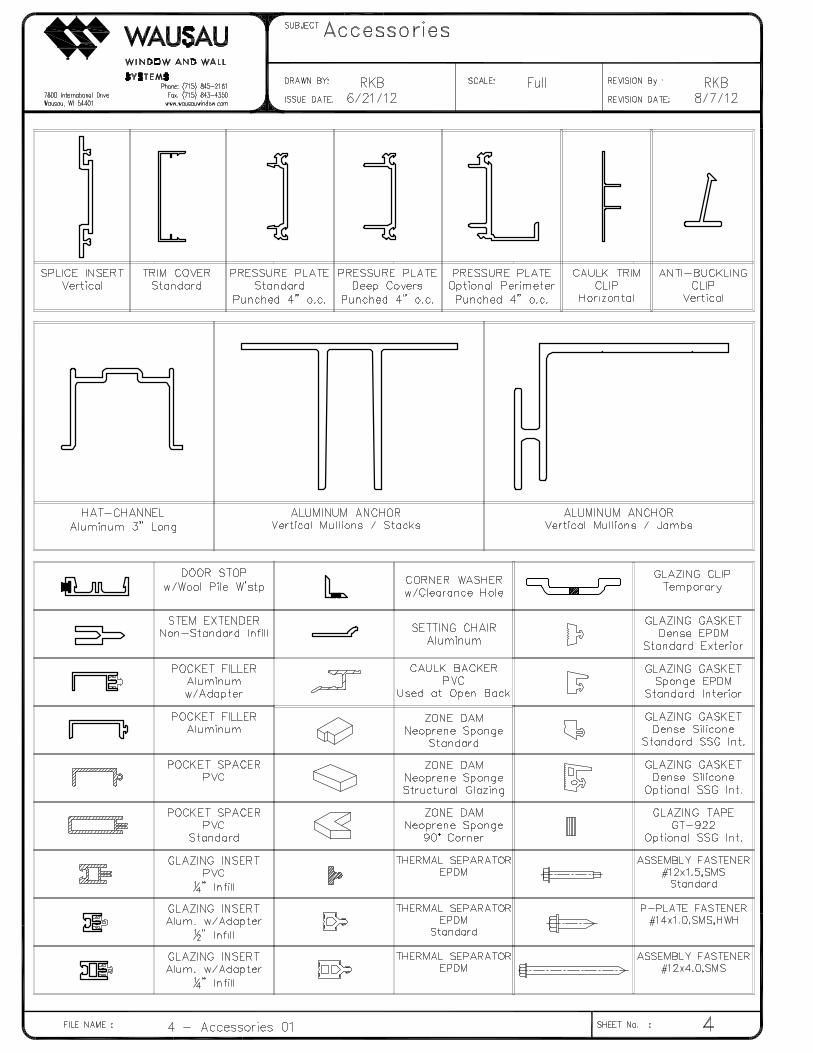
Accessories ………………………………………………………….. 4
Shop Notch Preparation ……………………………………………….. M-1
Assembly Hole Preparation – Open Back Jambs …………………………………….. M-2
Assembly Hole Preparation – Open Back Jambs …………………………………….. M-2a
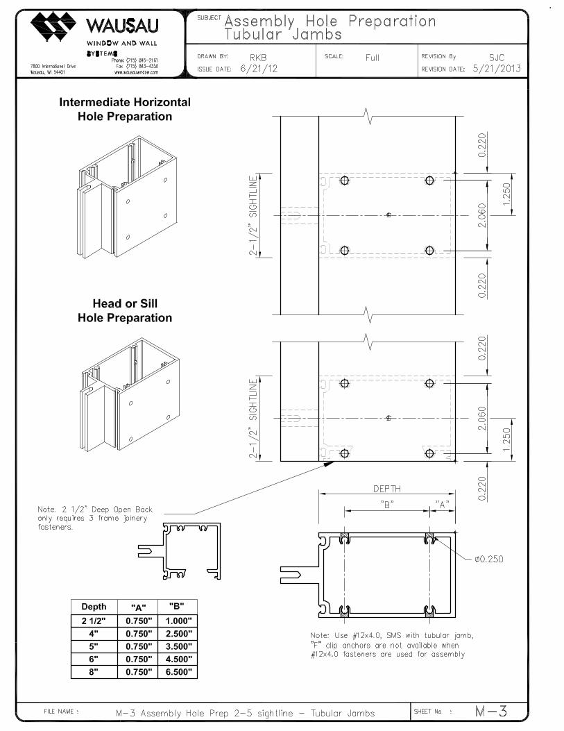
Assembly Hole Preparation – Tubular Jambs …………………………………….. M-3
Assembly Hole Preparation – Mullions ………………………………………………. M-4
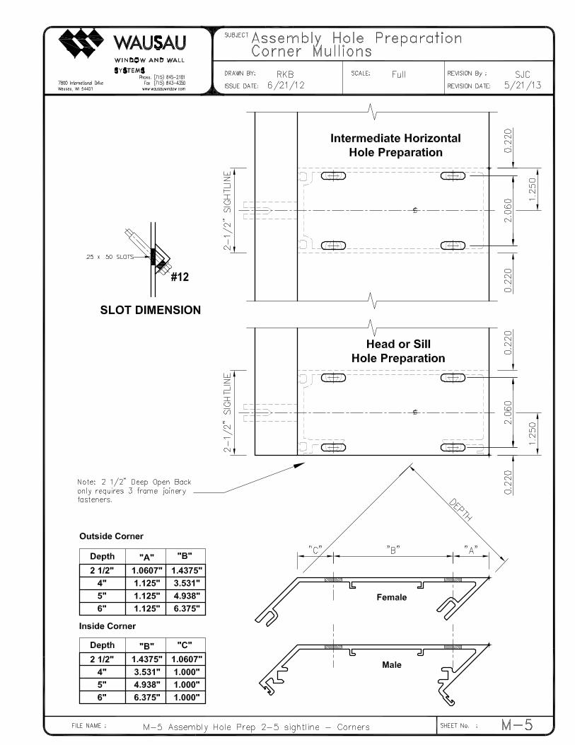
Assembly Hole Preparation – Corners ………………………………………………. M-5
Installation Elevation ………………………………………………………….. ASY-1
Screw Spline Assembly & Unit Instillation …………………………………….. ASY-2
Screw Spline Assembly – Corners & Unit Instillation ………………………….. ASY-3
Screw Spline Assembly – Corners & Unit Instillation ………………………….. ASY-3a
Frame Joinery & Perimeter Sealing …………………………………….. ASY-4
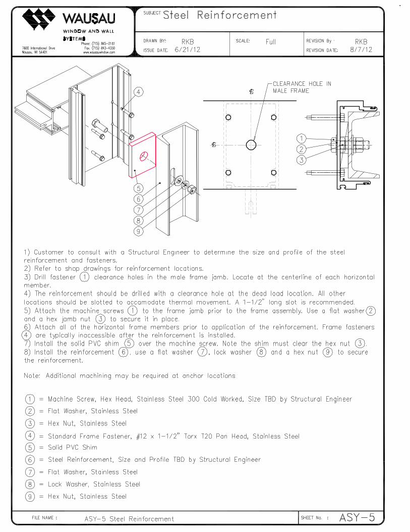
Steel Reinforcement ……………………………………………….. ASY-5
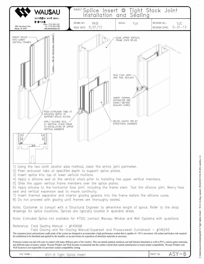
Splice Insert @ Tight Stack Joint – Stack …………………………………….. ASY-6
Splice Insert @ Tight Stack Joint – Tube …………………………………….. ASY-6a
Splice Insert @ Expansion Joint ……………………………………………….. ASY-7
Perimeter Anchor – Formed Steel ……………………………………………….. ASY-8
Perimeter Anchor – “T” & “F” Clips ……………………………………………….. ASY-9
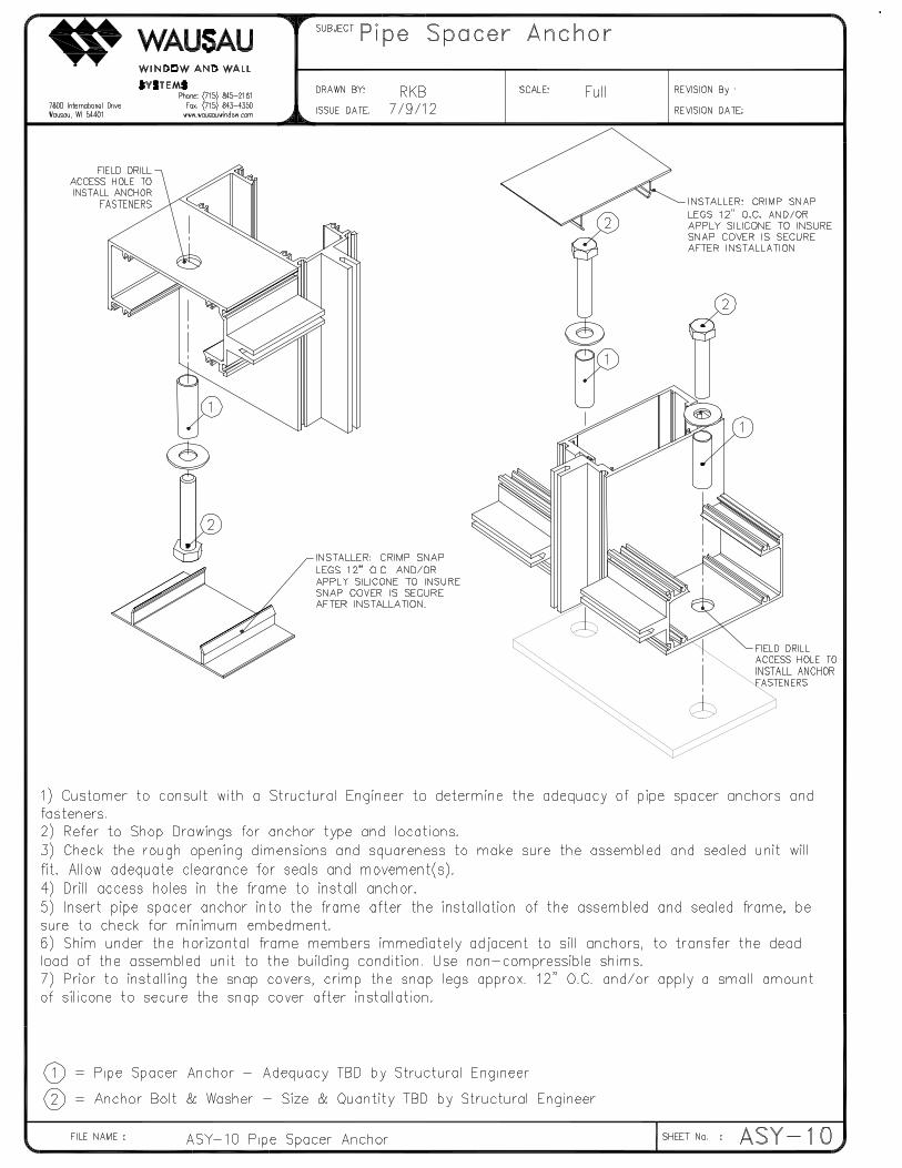
Pipe Spacer Anchor …………………………………………………………. ASY-10
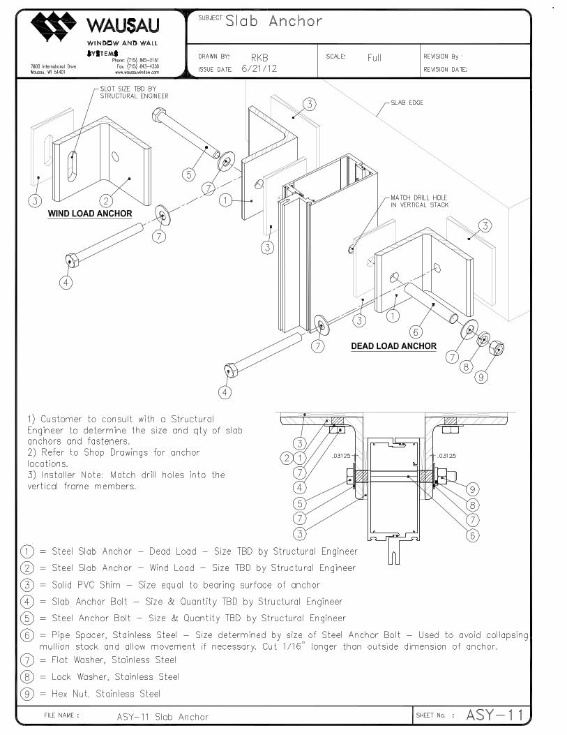
Slab Anchor …………………………………………………………. ASY-11
Perimeter & Expansion Joint Sealing ……………………………………………….. ASY-12
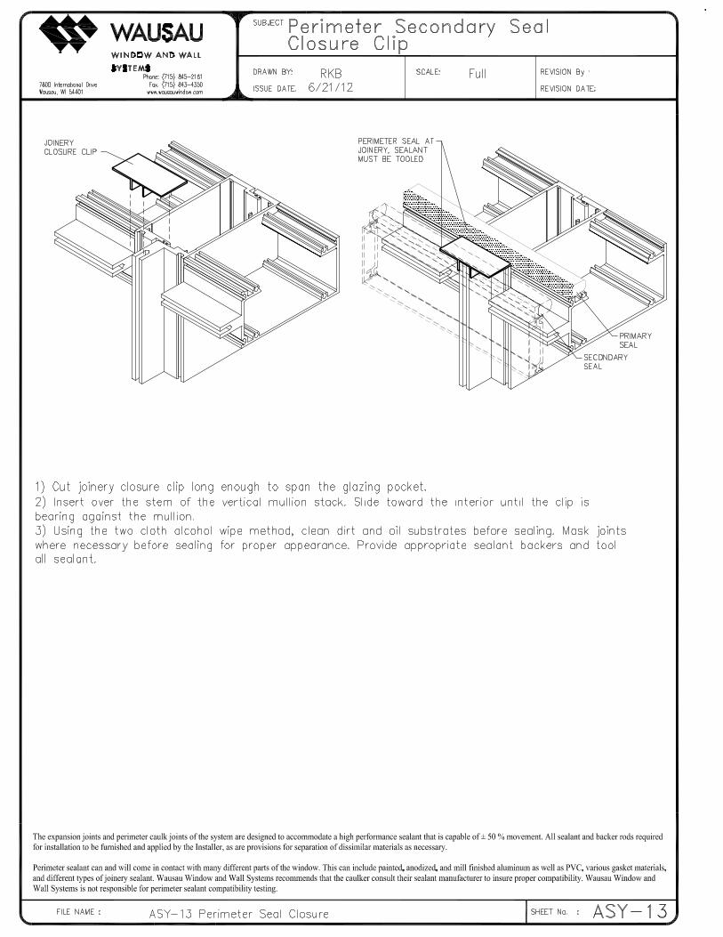
Perimeter Seal Closure Clip …………………………………………………………. ASY-13
Door Opening Preparation …………………………………………………………. ASY-14
Anti-Buckling Clips …………………………………………………………. ASY-15
Sealing Guidelines …………………………………………………………. ASY-16
Frame Inspection, Cleaning and Preparation …………………………………….. ASY-18
Special Note: Advantage & Stock Length …………………………………….. ASY-19
Disclaimers …………………………………………………………. ASY-20


PART# 146245
ASY�16
SEALING GUIDELINES
References
In addition to the guidelines provided in this manual, Wausau Window and Wall Systems recommend that
Installers and General Contractors familiarize themselves with the latest editions of the following industry
guidelines:
• ASTM C1193 Standard Guide for Use of Joint Sealants
• ASTM C1472 Standard Guide for Calculating Movement and Other Effects When Establishing
Sealant Joint Width.
• AAMA 609 & 610�10 Cleaning and Maintenance Guide for Architecturally Finished Aluminum
• AAMA 800�10 Voluntary Spec. & Test Method for Sealants
• AAMA 851�09 Fenestration Sealants Guide for Windows, Window Walls and Curtain Walls
• AAMA JS�91 Joint Sealants
Compatibility Issues
Sealants may not adhere or maintain long�term adhesion to substrates if the surface is not prepared and
cleaned properly before sealant application. Using proper materials and following prescribed surface
preparation and cleaning procedures is vital for sealant adhesion. Perimeter sealant can and will come in
contact with many different parts of the window. This can include painted, anodized, and mill finished
aluminum as well as PVC, various gasket materials, and different types of joinery sealant. In all cases it is
important to confirm the acceptability of each sealant�substrate combination with a lab or site adhesion test
prior to proceeding with project installation. Sealant manufacturers can provide lab and field adhesion
testing information and suggestions.
The expansion joints and perimeter caulk joints of the system are designed to accommodate a high
performance sealant that is capable of ± 50% movement. All sealant and backer rods required for
installation to be furnished and applied by the Installer, as are provisions for separation of dissimilar
materials as necessary.
Surface Preparation
Non�Porous Materials (Glass, Metals, Plastics, etc.)
• Clean by using a two�rag wipe technique – wet one rag with “approved” solvent and wipe the
surface with it, then use the second rag to wipe the wet solvent from the surface before it
evaporates (allowing the solvent to dry on the surface without immediately wiping with a second
cloth can negate the cleaning procedure because the contaminants may simple be re�deposited as
the solvent dries). In all cases where used, solvents should be wiped dry with a clean, white cloth
or other lint�free wiping materials.
• Isopropyl Alcohol (IPA) is a common�used solvent and has been proven useful for most non�
porous substrates encountered in architectural construction applications. When handling solvents,
refer to the manufacturers MSDS for information on handling, safety and personal protective
equipment.
• Difficult or nearly impossible to see on a joint substrate, condensation or frost is likely to develop
on substrates when temperatures drop. Since moisture and frost will interfere with proper sealant
adhesion, it is important to confirm that substrates are dry prior to application of the sealant.

PART# 146245
ASY�17
Porous Materials (Concrete, Masonry, Brick, Stone, etc.)
• Joints must be clean, dry and sound prior to application of sealant. All contaminants, impurities, or
other adhesion inhibitors (such as moisture/frost, oils, concrete form release agents, old sealants,
asphalt and other surface treatments, etc.) must be removed from the surfaces to which the sealant
is intended to adhere.
• Clean where necessary by wire brush or mechanical abrading to provide a stable, clean surface for
sealant application.
• Remove dust and other remaining loose particles with a soft bristle brush or by using oil�free
compressed air.
• Polished stone surfaces and smooth sawn edges can be cleaned using a solvent dampened rag
(allow sufficient time for solvent to evaporate prior to application of the sealant). When handling
solvents, refer to the manufacturers MSDS for information on handling, safety and personal
protective equipment.
• Since porous material can absorb and retain moisture, it is important to confirm that substrates are
dry prior to application of the sealant.
Joint Movement
• All moving joints should be designed so as not to allow three�sided adhesion of the sealant to
occur. Three�sided adhesion hinders the ability of the sealant to extend and compress freely as
desired and can lead to early joint failure.
Joint Width
• The recommended sealant profile is an hourglass shape with the depth of the sealant over the
crown of the backer to be no thinner than ¼” and no thicker than ½”
• A minimum of ¼” of adhesive bonding contact must be made to all surfaces to which the sealant
is intended to adhere.
Joint Backer Materials
Backer materials, typically backer rod, provide the following benefits to aide in the correct application of
sealants.
• Control and provide the desired sealant depth.
• Create a formed joint cavity that allows for the desired sealant shape.
• Provide a firm backup which helps attain full wetting of the substrates when the sealant is tooled.
• Act as a bond breaker to eliminate adhesion on the backside of a joint (three�sided adhesion)
Tooling
• Tool or strike the sealant with a concave tool applying light pressure to spread the material against
the back�up material and the joint surfaces to ensure a void�free application.
• On sill applications, tool the sealant to shed water and to eliminate ponding.
• Tooling agents such as water, soap, or detergent solutions are not recommended.
Masking
Masking tape is recommended where appropriate to ensure a neat job and to protect adjoining surface from
over�application of sealant. Masking tape should be removed immediately after tooling the sealant and
before the sealant begins to skin over (tooling time).

PART# 146245
ASY�18
FRAME INSPECTION, CLEANING AND PREPARATION
Pre�Glaze Inspection of Frames:
• Glazing finalizes a series of fabrication, assembly, and installation steps. In many cases, the
glazing process will conceal defects that are critical to quality. Examples of defects include poor
part fit and flaws in sealant or sealant application. Defects in these areas can cause customer
dissatisfaction and significant call back cost. Pre�glazing inspection is the Glazier’s last chance for
quality verification.
Cleaning and Preparation:
• Glazing surfaces must be free of dirt, oil, existing glazing materials or other contaminants. Glazing
tape and sealants will not adhere to contaminated surfaces. Cleaning of new or existing glazing
surfaces is a critical step to ensure the quality of the glazing.
Inspection:
• Perform a visual inspection of frame sealant at each corner and inside open lites prior to glazing.
o Look for missed seals, gaps in the sealant, or defects in the surface of the sealant.
o Are all the joints sealed?
o Was the correct sealant used?
o Was the sealant applied properly?
• Pay special attention to hidden or shadowed areas. Use a flashlight if direct light is required.
• This inspection is the last chance to detect joinery sealing issues prior to glazing.
Cleaning of Frame Surfaces:
• Spray isopropyl alcohol onto clean cloth.
• Wipe glazing area until clean (Use two�cloth alcohol wipe method)
• Surface must be clean of oil and other residue.
• Repeat steps until glazing area is clean.
• Dispose of contaminated cloth immediately.
• After final wipe; immediately dry with a clean cloth.
• Do not use compressed air.
• Do not allow the isopropyl alcohol to pool and/or evaporate from the surface.
PART# 146245
ASY�19
Special Note regarding Advantage & Stock Length Projects
Advantage Wausau is an “order entry” product program, which utilizes customer�supplied information to
provide a wide selection of high�quality pre�engineered Wausau Window and Wall Systems, at competitive
pricing. As such, Wausau is not responsible for; a) Design or detailing of installation conditions; b) Review
of Architectural Drawings, Specifications, or local building/safety Codes, or compliance of products to
requirements contained therein; c) dimensioning; d) Structural adequacy of materials provided, or
substrates to which they are anchored; e) Thermal, seismic or building movement accommodation; f)
Sealant joint design, sizing or compatibility testing; g) Architectural or contractor approval; h)Field
measurement; or i) Other services typically included as part of the submission drawing process.
Wausau Advantage products have been tested to comply with industry standards. However, required
mullion size, anchor spacing, glass selection and other structural characteristics for any specific project
are dependent on specified Design Wind Pressures or Local Building Codes, as well as the unit sizes and
installation conditions. (Refer to the Series�specific Wind Load Charts provided for mullion I�Values.)
Structural design, adequacy of materials provided per customer order information, or fitness for a
particular application are not the responsibility of Wausau Window and Wall Systems.
Wausau will not check customer�supplied drawings, dimensions, or details for accuracy or completeness
during Order Entry. “String” dimensioning will be entered as shown on the Order Entry form, with no
provision made for summation of same. Always refer to the Wausau quotation for detailed exclusions and
qualifications specific to your project. By using the Order Entry Form the customer acknowledges that they
have read and are bound by this disclaimer.

PART# 146245
ASY�20
DISCLAIMERS
1. Field verification and/or field measurements will not be the responsibility of Wausau Window and Wall Systems unless specifically included
in our quotation. The general contractor is responsible for verifying all dimensions. The G.C. is to take note of all dimensions, as Wausau
Window and Wall Systems assumes no responsibility beyond manufacturing in accordance to dimensions shown on the approved drawings
and/or order entry documents. Make certain that the building construction which will receive your materials is in accordance with the
contract documents. Returned approved submission prints will indicate to Wausau Window and Wall Systems that all dimensions have been
verified and approved. These drawings embrace only the work in the Wausau Window and Wall Systems contract. Wausau Window and
Wall Systems does not assume responsibility for measurements affecting other contractors’ work. Issuance of shop drawings for approval
does not constitute acceptance of customer’s order by Wausau Window and Wall Systems. The order entry documents may take precedence
over shop drawings which in turn take precedence over other contract documents or product information and include specific details for the
project. The Assembly and Installation manual are of general nature and cover most common conditions.
2. The General Contractor shall provide the installing subcontractor with a building perimeter offset line on each floor, plumb with lines on the
floors below, and located at a point from the edge of the floor slab as designated. The General Contractor shall also provide clearly scribed
benchmarks on each floor on a column as designated. The General Contractor shall be responsible for the accuracy of the location of the
perimeter offset lines and the elevations of the benchmarks.
3. Wausau Window and Wall Systems does not supply installation fasteners, unless previously arranged with the Sales/Estimating department.
Masonry expansion plugs and screws occurring at the sill are to be set in sealant by the installer. The installer is to shim and securely anchor
the frames square and plumb. Dead load shims are required at the sill directly under the mullion and jambs (typical).
4. Window and wall systems must be stored in an area free from weather and construction hazards. Aluminum finish must be protected from
staining of wet cardboard or paper and from the action of harsh alkalis and sand in concrete, stucco, mortar or plaster. The setting of the
material prior to the setting of the other materials requires the G.C. to closely supervise other trades so as to protect marring or discoloration
from any cause. All glass and aluminum must be protected during any and all welding operations.
5. The expansion joints and perimeter caulk joints of the system are designed to accommodate a high performance sealant that is capable of
+/� 50% movement. Please consult the sealant manufacturer for proper surface preparation and bond breakers. All sealant, backer rods,
required for installation to be furnished and applied by the Installer, as are provisions for separation of dissimilar materials as necessary.
6. Perimeter sealant can and will come in contact with many different parts of the window. This can include painted, anodized, and mill
finished aluminum as well as PVC, various gasket materials, and different types of joinery sealant. Wausau Window and Wall Systems
recommend that the caulker consult their sealant manufacturer to ensure proper compatibility. Wausau Window and Wall Systems is not
responsible for perimeter sealant compatibility testing.
7. Request for a revision after Wausau Window and Wall Systems has been released for fabrication will result in an engineering and handling
charge plus the cost of the fabricated materials. This must be approved in writing prior to the revisions being made.
8. Upon delivery of Wausau Window and Wall Systems material to the project site, it is the responsibility of the customer to ensure that all
shipping damages and/or material shortages are acknowledged and reported to Wausau Window and Wall Systems within (2) two weeks
[(10) ten working days]. Damages or shortages reported after that time period may result in additional costs to the customer. Any common
carrier materials received damaged should be reported to Wausau Window and Wall Systems and the shipping company immediately upon
receipt.
9. Installer/Contractor accepts responsibility for the performance of all door/window/curtainwall systems if not installed per Wausau Window
and Wall Systems product information. Any and all cleaning of components is not by Wausau Window and Wall Systems. Final hardware
adjustment is not the responsibility of Wausau Window and Wall Systems.
10. Wausau Window and Wall Systems standard limited warranty applies, including all provisions therein. Refer to the project specific Wausau
Window and Wall Systems proposal for general terms and conditions of sale.
PROPRIETARY NOTICE
This document and the contents herein are the property of Wausau Window and Wall Systems and use by unauthorized parties is prohibited.
© 2012 Apogee Wausau Group