Embed Size (px)
Citation preview

Manuale d’istruzioneOperating and service manualMode d’emploi et d’entretienBedienungs- und WartungshandbuchManual de uso y mantenimiento
ORVED Srl Soc. Unipersonale - Via dell'Artigianato, 30 - 30024 MUSILE DI PIAVE (VE) ITALYTel.: ++39 0421 54387 - 340340 / Telefax: ++39 0421 333100 - 332295
E-mail: [email protected] - [email protected] - Internet: www.orved.it
AZIENDA CONSISTEMA DI GESTIONE
PER LA QUALITÁCERTIFICATO DA DNV
=UNI EN ISO9001:2000=
COMPANY WITHQUALITY MANAGE-
MENT SYSTEMCERTIFIED BY DNV
=UNI EN ISO9001:2000=
CONFEZIONATRICI SOTTOVUOTO A CAMPANA CON COMANDI DIGITALI - MARCATURA BUSTE CON DATA E LOTTO - INIEZIONE GAS.
VACUUM PACKER WITH DIGITAL CONTROLS - BAG PRINTING: DATE AND BATCH NUMBER - GAS INJECTION
CONDITIONNEUSES SOUS VIDE À CLOCHE AVEC COMMANDES NUMÉRIQUES - MARQUAGE SACHETS AVEC DATE ET LOT -INJECTION GAZ
KAMMER-VAKUUM-VERPACKUNGSMASCHINEN MIT DIGITALEN STEUERUNGEN - BEUTELBEDRUCKUNG MIT DATUM UND LOSNUMMER - BEGASUNG
ENVASADORAS AL VACÍO DE CAMPANA CON MANDOS DIGITALES - MARCADO DE BOLSAS CON FECHA Y Nº DE LOTE - INYECCIÓN DE GAS
REV. 01Ed. 11 - 2008
Cod.: 1500288
IT
EN
FR
DE
ES
CUISSON SV-31CUISSON SV-41
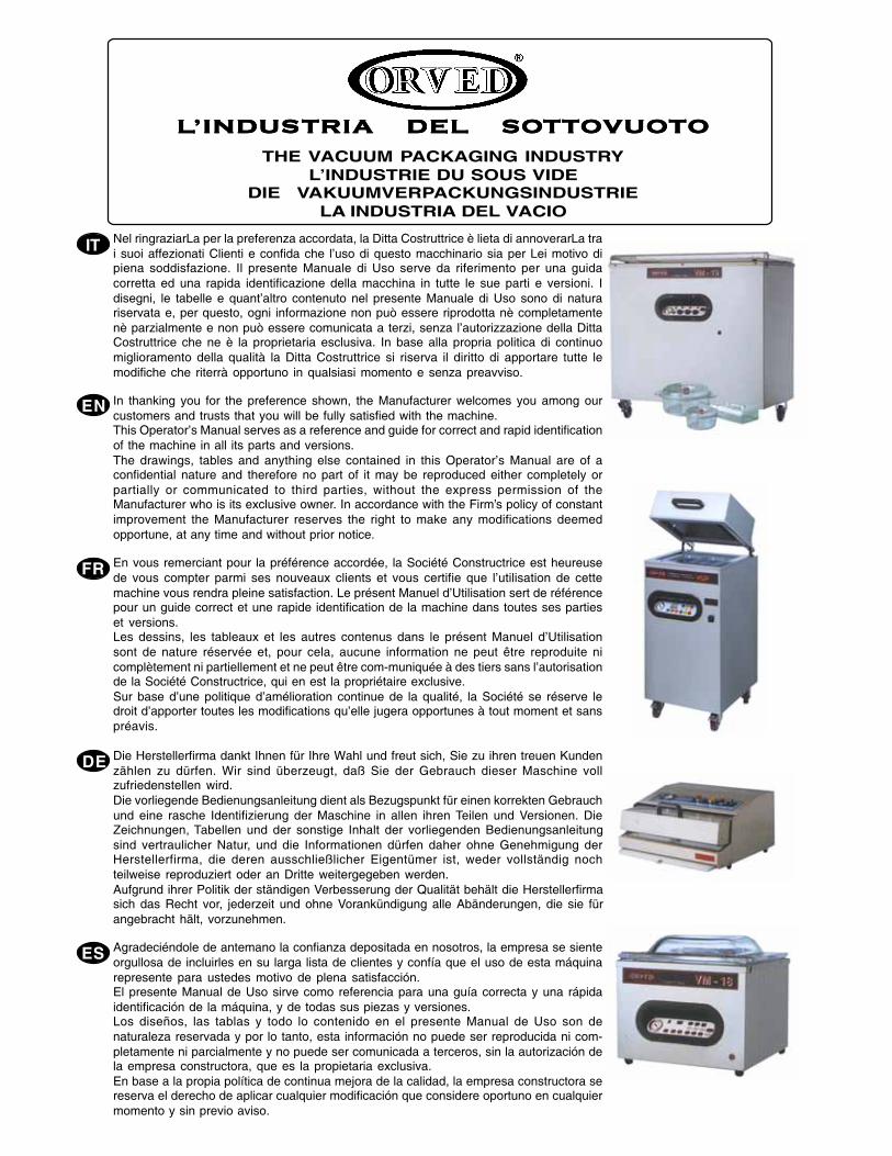
LLLLL’INDUS’INDUS’INDUS’INDUS’INDUSTRIA DEL SOTRIA DEL SOTRIA DEL SOTRIA DEL SOTRIA DEL SOTTTTTTTTTTOOOOOVUOVUOVUOVUOVUOTTTTTOOOOO
THE VACUUM PACKAGING INDUSTRYL’INDUSTRIE DU SOUS VIDE
DIE VAKUUMVERPACKUNGSINDUSTRIELA INDUSTRIA DEL VACIO
Nel ringraziarLa per la preferenza accordata, la Ditta Costruttrice è lieta di annoverarLa trai suoi affezionati Clienti e confida che l’uso di questo macchinario sia per Lei motivo dipiena soddisfazione. Il presente Manuale di Uso serve da riferimento per una guidacorretta ed una rapida identificazione della macchina in tutte le sue parti e versioni. Idisegni, le tabelle e quant’altro contenuto nel presente Manuale di Uso sono di naturariservata e, per questo, ogni informazione non può essere riprodotta nè completamentenè parzialmente e non può essere comunicata a terzi, senza l’autorizzazione della DittaCostruttrice che ne è la proprietaria esclusiva. In base alla propria politica di continuomiglioramento della qualità la Ditta Costruttrice si riserva il diritto di apportare tutte lemodifiche che riterrà opportuno in qualsiasi momento e senza preavviso.
In thanking you for the preference shown, the Manufacturer welcomes you among ourcustomers and trusts that you will be fully satisfied with the machine.This Operator’s Manual serves as a reference and guide for correct and rapid identificationof the machine in all its parts and versions.The drawings, tables and anything else contained in this Operator’s Manual are of aconfidential nature and therefore no part of it may be reproduced either completely orpartially or communicated to third parties, without the express permission of theManufacturer who is its exclusive owner. In accordance with the Firm’s policy of constantimprovement the Manufacturer reserves the right to make any modifications deemedopportune, at any time and without prior notice.
En vous remerciant pour la préférence accordée, la Société Constructrice est heureusede vous compter parmi ses nouveaux clients et vous certifie que l’utilisation de cettemachine vous rendra pleine satisfaction. Le présent Manuel d’Utilisation sert de référencepour un guide correct et une rapide identification de la machine dans toutes ses partieset versions.Les dessins, les tableaux et les autres contenus dans le présent Manuel d’Utilisationsont de nature réservée et, pour cela, aucune information ne peut être reproduite nicomplètement ni partiellement et ne peut être com-muniquée à des tiers sans l’autorisationde la Société Constructrice, qui en est la propriétaire exclusive.Sur base d’une politique d’amélioration continue de la qualité, la Société se réserve ledroit d’apporter toutes les modifications qu’elle jugera opportunes à tout moment et sanspréavis.
Die Herstellerfirma dankt Ihnen für Ihre Wahl und freut sich, Sie zu ihren treuen Kundenzählen zu dürfen. Wir sind überzeugt, daß Sie der Gebrauch dieser Maschine vollzufriedenstellen wird.Die vorliegende Bedienungsanleitung dient als Bezugspunkt für einen korrekten Gebrauchund eine rasche Identifizierung der Maschine in allen ihren Teilen und Versionen. DieZeichnungen, Tabellen und der sonstige Inhalt der vorliegenden Bedienungsanleitungsind vertraulicher Natur, und die Informationen dürfen daher ohne Genehmigung derHerstellerfirma, die deren ausschließlicher Eigentümer ist, weder vollständig nochteilweise reproduziert oder an Dritte weitergegeben werden.Aufgrund ihrer Politik der ständigen Verbesserung der Qualität behält die Herstellerfirmasich das Recht vor, jederzeit und ohne Vorankündigung alle Abänderungen, die sie fürangebracht hält, vorzunehmen.
Agradeciéndole de antemano la confianza depositada en nosotros, la empresa se sienteorgullosa de incluirles en su larga lista de clientes y confía que el uso de esta máquinarepresente para ustedes motivo de plena satisfacción.El presente Manual de Uso sirve como referencia para una guía correcta y una rápidaidentificación de la máquina, y de todas sus piezas y versiones.Los diseños, las tablas y todo lo contenido en el presente Manual de Uso son denaturaleza reservada y por lo tanto, esta información no puede ser reproducida ni com-pletamente ni parcialmente y no puede ser comunicada a terceros, sin la autorización dela empresa constructora, que es la propietaria exclusiva.En base a la propia política de continua mejora de la calidad, la empresa constructora sereserva el derecho de aplicar cualquier modificación que considere oportuno en cualquiermomento y sin previo aviso.
EN
FR
ES
DE
IT

29REV. 01 - Cod.: 1500288
EN
Operation and maintenance manual / Ed. 11 - 2008
EN
CUISSON SV-31 • SV-41 INDEX
1. PREFACE ................................................................................................................................................................................. 30
1.1 INTRODUCTION .................................................................................................................................................................... 301.2 IMPORTANT ............................................................................................................................................................................ 301.3 PRESERVATION ..................................................................................................................................................................... 30
2. GENERAL INFORMATION ........................................................................................................................................................ 31
2.1 MANUFACTURER’S IDENTIFICATION ................................................................................................................................... 312.2 APPLIANCE IDENTIFICATION ................................................................................................................................................ 312.3 TECHNICAL SERVICE ........................................................................................................................................................... 312.4 GENERAL SAFETY REGULATIONS ....................................................................................................................................... 32
3. PRELIMINARY INFORMATION ................................................................................................................................................. 34
3.1 TECHNICAL DATA .................................................................................................................................................................. 343.2 FIELD OF USE ........................................................................................................................................................................ 36
4. HANDLING AND UNPACKING .................................................................................................................................................. 36
4.1 GENERAL WARNINGS........................................................................................................................................................... 364.2 UNPACKING ........................................................................................................................................................................... 364.3 HANDLING AND STORAGE ................................................................................................................................................... 36
5. INSTALLATION ........................................................................................................................................................................ 36
5.1 APPLIANCE DESCRIPTION ................................................................................................................................................... 365.2 POWER SUPPLY VOLTAGE ................................................................................................................................................... 385.3 APPLIANCE OVERHEATING PROTECTION SAFETY DEVICE ............................................................................................ 395.4 GENERAL INSTRUCTIONS FOR USE .................................................................................................................................. 395.5 CONTROL PANEL .................................................................................................................................................................. 415.6 DEFINITONS OF FUNCTIONS ............................................................................................................................................... 41
6. USING THE MACHINE .............................................................................................................................................................. 43
6.1 PREPARATION ....................................................................................................................................................................... 436.2 OPERATION AND PROGRAMMING........................................................................................................................................ 45
7. MAINTENANCE ....................................................................................................................................................................... 48
7.1 GENERAL WARNINGS........................................................................................................................................................... 487.2 PROGRAMMED MAINTENANCE ............................................................................................................................................ 487.3 CARE AND CLEANING OF THE VACUUM PACKAGING MACHINES ..................................................................................... 487.4 ROUTINE MAINTENANCE ..................................................................................................................................................... 507.5 TROUBLESHOOTING ............................................................................................................................................................ 53
8. DISPOSAL OF THE MACHINE AND ITS PARTS ...................................................................................................................... 54
8.1 DISPOSAL OF PNEUMATIC SPRINGS .................................................................................................................................. 54
9. SPARE PARTS- GENERAL WARNINGS ................................................................................................................................... 54
10. FROM THE MANUFACTURER .................................................................................................................................................. 54
11. SPARE PARTS .............................................................................................................................................................. 133-134
EN
30
EN
REV. 01 - Cod.: 1500288Operation and maintenance manual / Ed. 11 - 2008
CUISSON SV-31 • SV-411. PREFACE
1.1 INTRODUCTIONThis document has been prepared and checked carefully to provide reliable information;The manufacturer declines all responsibility, whether implicit or explicit, for eventual errors and omissions.
The descriptions and images in this Manual are not binding; the Manufacturer reserves the right to modify the documentation and technical featuresof the appliance at any moment and without any prior notice.
1.2 IMPORTANTThis document, prepared by ORVED S.r.l. , provides all the information necessary for use, preservation and disposal of the appliance.
IIn case of doubt, contact:
ORVED Srl Soc. Unipersonale - Via dell'Artigianato, 30 - 30024 MUSILE DI PIAVE (VE) ITALYTel.: ++39 0421 54387 / Telefax: ++39 0421 333100
for technical problems and assistance: Tel. e fax:++39 0421 337154for orders: Tel.++39 0421 340340 fax:++39 0421 332295
E-mail: [email protected] - Internet: www.orved.it
This document forms an integral part of the appliance and as such must be preserved throughout its life and use; if the appliance is passed on to thirdparties, this document must also be handed over to the new owner.
Read this Manual entirely before carrying out any operation on the appliance.
ORVED will provide all the clarification necessary for use, maintenance and preservation of your Appliance.
The Buyer must make sure the operators concerned with use and maintenance of this appliance read this Manual entirely;it must always be readily available for consultation.
It is the Buyer’s responsibility to make sure, all amendments, updates or technical modifications communicated by the manufacturer are incorporatedinto the Manual.
Follow all the recommendations and directives given in this Manual because safe operation and preservation of theappliance depend on the correct use and application of the suggestions given below.
The manufacturer declines all responsibility for damage to persons, objects and animals deriving from failure to observe therecommendations given in this Manual, the safety warnings, and modifications made on the appliance without authorization,tampering with the appliance and the use of non original spare parts.
1.3 PRESERVATIONThis document must be used without damaging the contents.
Do not remove, tear or rewrite any parts of the Manual; while consulting it, do not use, greasy or dirty hands to turn the pages to avoid affecting thequality and life of the Manual.
After use, put the Manual back in a safe protected place easily accessible to operators involved in appliance use and maintenance.
If the Manual is lost or stolen or damaged, request a copy by sending a copy of the purchase order to ORVED, specifying the version, edition, revisionand the name of the appliance. This information is indicated on every page of the document.
Date of publication of this Use and Maintenance Manual: 11.2008.Copyright: ORVED S.r.l. Societá Unipersonale Musile di Piave (VE)
Unauthorized use is forbidden.The manufacturer reserves the right to make technical modifications at any moment without prior notice.
PREFACE

EN
31
EN
REV. 01 - Cod.: 1500288 Operation and maintenance manual / Ed. 11 - 2008
CUISSON SV-31 • SV-412. GENERAL INFORMATION
2.1 MANUFACTURER’S IDENTIFICATIONHead Office:ORVED Srl Soc. Unipersonale - Via dell'Artigianato, 30 - 30024 MUSILE DI PIAVE (VE) ITALYTel.: ++39 0421 54387 / Telefax: ++39 0421 333100E-mail: [email protected] - Internet: www.orved.it
2.2 APPLIANCE IDENTIFICATIONThe appliance is identified by means of a rating plate (see image) applied on the back, which bears the following information:
General data:• Manufacturer’s Name and Address:
Orved Srl - Via Dell’Artigianato, 30 - 30024 MUSILE DI PIAVE (VE)• Model and CE marking
Technical features:• Rated voltage, frequency and power
WARNING: It is absolutely forbidden to tamper with, engrave, alter, or remove the nameplate from the appliance. Do notcover it with adhesive tape or other such material as it must always be clearly visible.
WARNING: If the nameplate is found to be damaged for any reason whatsoever, (detached from the machine, damaged oronly partly legible) notify the manufacturer immediately.
2.3 TECHNICAL SERVICE
2.3.1 WARRANTY
All ORVED products are normally subjected to severe quality and functional checks before installation to ensure safety and in the interests of ourClients.
2.3.1.1 COVERAll ORVED products are covered by a warranty for manufacturing and machining defects, and we undertake to replace parts found to be defectiveby the manufacturer free of charge.
2.3.1.2 DURATIONORVED products come with a twelve-month warranty from the date indicated on the purchase document.
2.3.1.3 GENERAL CONDITIONSAccording to the ORVED warranty:a) The warranty gives exclusive rights for free replacement of components acknowledged as defective by ORVED or our authorized representative.b) ORVED’s responsibility is limited exclusively to replacing parts found to be defective; we shall not acknowledge claims for any other kind of
damage.c) The Client is entirely responsible for returning disputed and/or defective parts to the ORVED office, and all transport charges for delivering the
parts.d) Parts subject to normal wear are excluded from the warranty.e ) Repairs, if any, do not in any manner lead to extension of the warranty.
2.3.1.4 TERMINATIONApart from the normal validity period, the warranty will immediately lapse in the following cases:a) Appliance nameplate tampered with, altered in any manner or removed without informing the manufacturer immediately.b) Modifications on the appliance or its parts without written authorization from the manufacturer. Tampering with the appliance or its parts, apart
from invalidating the warranty, will free ORVED of all liability for all damage to persons, animals or objects.c) Failure to respect the indications in this Manual.d) Using the appliance for purpose other than that specified in this Manual.e ) Damage or accident to the appliance deriving from outside factors.f) Conduction, repair and/or maintenance operations carried out by untrained personnel.
2.3.2 NOTIFYING DEFECTS OR FAULTS
WARNING: Defects and faults must be notified to the area dealer or directly to the manufacturer.
2.3.3 ORDERING SPARE PARTS
WARNING: Spare parts must be ordered from the area dealer or directly from the manufacturer, indicating the article code(See SPARE PARTS Chapter).
GENERAL INFORMATION

EN
32
EN
REV. 01 - Cod.: 1500288Operation and maintenance manual / Ed. 11 - 2008
CUISSON SV-31 • SV-412.4 GENERAL SAFETY REGULATIONS
ORVED has analyzed the fundamental operations regarding use and maintenance for the design and construction of the appliance; the operatingmethods are studied and described in this Manual to allow safe operation.
CAUTION: Failure to observe these regulations can be extremely hazardous for safety of the appliance and persons.
2.4.1 SYMBOLS
Symbols and texts in different styles have been used in this Manual to highlight certain situations involving risk for the appliance or operator safety,particularly important regulations, recommendations, warnings and precautions to be taken during use and Maintenance.The personnel involved in the use and maintenance of the appliance must understand these symbols before carrying out any operation on it.
GENERAL INFORMATION
SYMBOL SIGNAL MEANING
ELECTRIC HAZARD! Indicates immediate danger for the person’s life and health.Failure to observe these warnings may lead to serious damage to health, or even mortalinjury.
DANGER ! Indicates probable danger for the person’s life and health.Failure to observe these warnings may lead to serious damage to health or even mortalinjury.
ATTENTION ! Indicates possible danger. Failure to observe these warnings may lead to minor woundsand material damage.
WARNING ! Indicates a possible damage situation.Failure to observe these warnings may lead to material and environmental damage.
IMPORTANT ! Indicates recommendations for use and other useful information.
INFORMATION SERVICE The presence of this symbol alongside the text implies the obligation to inform themanufacturer of a particular situation or the possibility of requesting information regardinga certain topic.
RISK OF BURNS Indicates immediate danger in case of contact with very hot surfaces.
2.4.2 WARNINGS AND HAZARDS DERIVING FROM USE OF THE MACHINE
2.4.2.1 HAZARDS DERIVING FROM USE OF THE MACHINE
DANGER! The machines are designed and constructed according to the latest technology available and conform to applicablesafety standards. In spite of this, they may be a source of hazard, especially if the safety instructions given in this Manualare not observed. Immediately eliminate all faults and problems that can affect safety!
2.4.2.2 MACHINE OPERATORS
DANGER! The machine must be used only by trained operators.Such operators must be familiar with the safety standards and operating instructions given in this Manual.
This appliance is not suitable for use by persons (including children) with reduced physical, sensory and mental capacities,or who are unskilled, unless they are supervised and trained regarding use of the appliance by a person responsible for theirsafety. Children must not be allowed to play with the appliance.
2.4.2.3 PROTECTIVE AND SAFETY DEVICES
DANGER! Before starting up the machine, check to ensure that all the safety and protective devices are present and inperfect working order.
2.4.2.4 ELECTRIC HAZARDS
ELECTRIC HAZARD!- Only qualified personnel are permitted to work on the electric system and access live parts of the machine.- Check the machine’s electric system regularly.
- Remove and/or replace slackened connections or burnt wires immediately (replacement must be done exclusively by qualified personnel).- Use only plugs and sockets suitable for the electrical features shown on the machine’s nameplate.- Do not insert objects in the machine’s air vents: danger of electric shock!- Do not use running water, water jets and/or steam in the machine installation area:
danger of electric shock!
2.4.2.5 MACHINE MAINTENANCE, SERVICING AND REPAIR
DANGER!- Remove the plug from the power socket before carrying out any operation.- Carry out all machine maintenance and servicing operations punctually.
- Damage, if any, must be repaired exclusively by qualified personnel.

EN
33
EN
REV. 01 - Cod.: 1500288 Operation and maintenance manual / Ed. 11 - 2008
CUISSON SV-31 • SV-41 GENERAL INFORMATION
2.4.2.6 MODIFYING THE APPLIANCE
DANGER!-Do not make any modifications or changes on the machine without the manufacturer’s permission.
- Replace all deteriorated, worn or damaged parts immediately (replacement must be done by a qualified technician).- Use only genuine spare parts.
2.4.2.7 FIRE PREVENTION
DANGER!- Keep the air vents clear (distance from surrounding parts at least 10 cm).- Do not place the machine near inflammable products.
DANGER! Danger of burns: if alcohol-based or inflammable products are used for disinfecting, air the area. Do not usenaked flames near the machine! Do not smoke!
2.4.2.8 CLEANING AND DISMANTLING THE MACHINE
CAUTION!-Clean the machine regularly by following the instructions given in this Manual.Use and handle cleaning products according to the manufacturer’s instructions.
-Scrapping and disposal of the machine, parts and products used for cleaning the machine must be done strictlyin compliance with the applicable standards.
2.4.2.9 HAZARDS DERIVING FROM PNEUMATIC SPRINGS APPLIED ON THE PLEXIGLAS COVER
DANGER!-Never open the pneumatic springs, as the pressure inside them is extremely high(about 180 bar).-Before scrapping the machine, discharge the pneumatic springs. Request instructions for disposal.
2.4.2.10 HAZARDS DERIVING FROM USE OF GAS.
DANGER!-Use only nitrogen N2 or carbondioxide CO2 or nitrogen+carbondioxide mixture N2 -CO2.-Detonation hazard! Do not use oxygen O2 or other explosive or inflammable gases.
-Observe the gas producer’s instructions strictly for correct use of gas cylinders and gas pressure reducers!

EN
34
EN
REV. 01 - Cod.: 1500288Operation and maintenance manual / Ed. 11 - 2008
CUISSON SV-31 • SV-413. PRELIMINARY INFORMATION
3.1 TECHNICAL DATA
PRELIMINARY INFORMATION
DESCRIPTION SV-31 SV-41
Standard: 220-240 V/1Ph+N+PE/50-60HzSpecial: 110-120 V/1Ph+N+PE/60HzSpecial: 110-115V/1Ph+N+PE/60Hz
Standard: 220-240V/1Ph+N+PE/50-60Hz
Special: 110-115V/1Ph+N+PE/60Hz
230V MONOPHASE VERSION (Rif. D)
110V MONOPHASE VERSION (60Hz)
WEIGHT (kg) KG 58,40 KG 100,00
DIMENSIONS (mm) A=440 mm A=555B==615 mm (PUMP INCLUDED) B=620H1=430 mm H1=455H2=740 mm H2=820
POWER SUPPLY VOLTAGE (V)FREQUENCY (Hz)
VACUUM CHAMBER DIMENSIONS (mm) Horizontal compartment: 330x432xH100 (Rif. A) Horizontal compartment: 435x500xH110 (Rif. A)Vertical compartment: 280x105x190 (Rif. B) Vertical compartment: 385x105xH190 (Rif. B)
LID Plexiglas – dome H60mm Plexiglas – dome H70mm
LENGTH OF SERVICEABLE SEALING EDGE (mm) 310 415
MAXIMUM BAG SIZE (mm) 300x450 400X550
MAXIMUM LIQUID PRODUCT VOLUME 5 5WHICH CAN BE PACKED IN THE VERTICALCOMPARTMENT (DENSITY=1) (lt) (Ref. C)
PUMP FLOW (m³/h) 12 (14 a60Hz) 25
FINAL PRESSURE (millibar) 2 0,5
MAXIMUM ABSORBED POWER (VA) 750 1200
PROTECTION FUSES (A) Pump fuse (PF1): 8 delayed Pump fuse (PF1): 10Sealing fuse (PF2): 2,5 delayed Sealing fuse (PF2): 2.5Power board fuse (PF3): 1 Power board fuse (PF3): 1Power board fuse (PF4): 4 Power board fuse (PF4): 4Dater safety timer (PFT): 3,15 Dater safety timer (PFT): 3,15
PROTECTION FUSES (A) Pump fuse (PF5): 16 delayed Pump fuse (PF5): 20 (ceramic)Sealing fuse (PF2): 5 Sealing fuse (PF2): 5Power board fuse (PF3): 2 Power board fuse (PF3): 1Power board fuse (PF4): 4 Power board fuse (PF4): 4Dater safety timer (PF1): 3,15 Dater safety timer (PFT): 3,15Dater safety timer (PF2): 200mA Time
TYPE OF OIL PUMP OIL LOAD (lt.) SW40 0,30 Lt ORV60 (FDA certified – class ISO 68)
ENVIRONMENT OPERATING CONDITIONS Temperature: 12-40°C Temperature: 12-40°CHumidity: 10-80% Humidity: 10-80%
NOISE EMISSIONS (dB) 50Hz= 60 60Hz=62 50Hz= 60 60Hz=62
FREQUENCY OF OIL CHANGE 12500/100 every 100 working hours(in work cycles)/hours
CONTROLS Digital 10 programmes Digital 10 programmes
STANDARD FEATURES Vacuum sensor Vacuum sensorGas injection system with 1 nozzles Gas injection system with 2 nozzles1 daters for printing date / batch no. 2 daters for printing date / batch no.
OPTIONS Yars

EN
35
EN
REV. 01 - Cod.: 1500288 Operation and maintenance manual / Ed. 11 - 2008
CUISSON SV-31 • SV-41 PRELIMINARY INFORMATION
•PFT
B
••
A
•
C
H1 H1
H2 H2
A A
B B
SV-31 SV-41
D
• •
•
•
PF3PF1
PF2
PF4

EN
36
EN
REV. 01 - Cod.: 1500288Operation and maintenance manual / Ed. 11 - 2008
CUISSON SV-31 • SV-41HANDLING AND UNPACKING
3.2 FIELD OF USE
The Vacuum packaging machine is designed and constructed for creating vacuum in bags and rigid containers.The machine must not be used in other ways or for purposes other than that indicated by the manufacturer in this Manual. Conformant use of themachine also involves abiding by and understanding the warnings and notices in this instruction Manual, as well as prompt checking, maintenanceand cleaning operations.
DANGER! The manufacturer declines all responsibility for damage to persons, animals and objects deriving from nonconforming use of the machine.
4. HANDLING AND UNPACKING
4.1 GENERAL WARNINGS
Pay attention to metal tips, nails, rivets, sharp edges and everything else that could be a potential source of risk on the packing. On receiving themachine, the Client must check to make sure it is intact, and inform the haulage contractor, or the transport personnel immediately of problems, missingparts or evident damage; this must be done before proceeding with other handling or unpacking operations.
WARNING: Damage, if any, on the packing may mean possible damage to the machine or its parts; in case of doubtregarding the actual condition of the machine following transport, contact the manufacturer for information, before
carrying out any other operation.
WARNING: The packed machine must be kept in a safe, dry place, covered and protected from environmental agents. Thestorage area temperature must be between 5°C and 40°C and the relative humidity not more than80%.
4.2 UNPACKING
After removing the packing, check to make sure the machine is intact; do not use it if in doubt and contact the dealer immediately. The packagingmaterials (plastic bags, etc.), must be kept out of the reach of children, and not dumped in the environment. Keep the packaging materials for futurehandling or storage of the machine.
WARNING: Disposal of the packing materials must be done in accordance with the Directives on the matter applicable in thecountry in which the machine is installed.
4.3 HANDLING AND STORAGE
- In case of transport within the installation area, the machine must always be kept in the horizontal position to avoid oil leaks from the pump. Thesealing bars and insertion plates must be fixed to prevent their shifting inside the vacuum chamber.
- In case of storage:The machine must be stored in a safe place, suitable for the purpose, dry, ventilated, covered, and sheltered from atmospheric agents. The storagearea temperature must be between 5°C and 40°C with a relative humidity value not higher than 80%. The installation area must be free of waterand water vapour.
If a machine has remained unused for long periods, change the pump oil before re-using it, by following the instructionsgiven in the “MAINTENANCE” chapter.
5. INSTALLATION
5.1 APPLIANCE DESCRIPTION
CUISSON domed vacuum packer machines are suitable for packing to pack both dry and/or seasoned products, as well as liquids, thanks tothe shape and structure of the vacuum chamber which allows bags containing liquid products to be positioned vertically. Furthermore it canprint the bag with the date and batch number. The appliance is equipped with digital controls with vacuum sensor control and has tenprogrammes which can be set by the user.
The machine is made up of the following main parts:
• a stainless steel compartment (A) (vacuum chamber or “cave”), equipped with a vertical compartment for packing bags containing liquids (B),inside of which the vacuum is created and sealing of the bag is performed by a sealing bar (C). The vacuum chamber is equipped with atransparent openable, Plexiglas lid (D), through which the work phases can be observed. The internal depth of the horizontal and verticalcompartments can be adjusted using special plastic shelves (E). The compartment is also equipped with a device (dater) (F) for printing the dateand batch number on the bags.
• a stainless steel body (G). The control panel and power switch are located on the front of the body while the rear is closed by a stainless steelpanel (H).Pump oil can be topped up through the left-hand side panel (I - SV-41) and the rear of the machine (SV-31 Fig. 1). The union for connecting thegas canisters is located on the rear of the unit (left-hand side) (L - SV-41 Fig. 2) and in the centre (SV-31 Fig. 1);
• a high-performance, 25-m3/h vacuum pump (M) with recirculating oil and an inspection window (N) for checking the oil level.
• an air suction system made up of connectors, tubes and solenoid valves which connect the vacuum chamber to the pump and components whichregulate and/or control the system;
• an electrical system including an electronic power board with fuse holders, control and connection board (O). All functions are controlled by amicroprocessor.

EN
37
EN
REV. 01 - Cod.: 1500288 Operation and maintenance manual / Ed. 11 - 2008
CUISSON SV-31 • SV-41 INSTALLATION
•
E
••
F
•
C
•
F
•
B
•
•
N
M
•
I
SV-31
•
G
•
•
A
D
Fig. 1
•
M
•
O•
•
L N
•
H
SV-41
•
O
•
A
•
G
•D
•
H
Fig. 2
•
L
SV-41

EN
38
EN
REV. 01 - Cod.: 1500288Operation and maintenance manual / Ed. 11 - 2008
CUISSON SV-31 • SV-41
Fig. 1
5.2 POWER SUPPLY VOLTAGE
5.2.1 230V SINGLE-FASE POWER SUPPLY (STANDARD)
For connection to the power supply, the appliance is equipped with a standard large two-pin plug, 2P+T-10/16A. Insert the plug in compatible socket connected to the mains supply in the installation area.
ELECTRIC HAZARD! Before making the connection, always check to make sure theelectrical features of the system in the installation area are suitable.
5.2.2 400V THREE-PHASE SUPPLY VOLTAGE
For connection to the power supply, the appliance is equipped with a CEE 3P+T/16A plug. Insert the plug ina compatible socket connected to the mains supply of the installation area.
ELECTRIC HAZARD! Before making the connection, always check to make sure theelectrical features of the system in the installation area are suitable and check thedirection of pump rotation.
5.2.3 CHECKING THE DIRECTION OF PUMP ROTATION IN THE THREE-PHASE VERSION
Procedure:
a) Check to make sure the voltage indicated on the machine nameplate corresponds to that of your mains supply (Fig. 1).
b) Insert the plug in the socket with the machine Off.
c) Check the oil level in the pump through the glass window provided on it (Fig. 2).If the level is insufficient, follow the instructions described in the “CHANGING THE PUMP OIL” Chapter.
d) Regulate the ‘VAC’ function on the control panel to the maximum value of 99% (Fig. 3).
e ) Lift the plexiglas lid after lowering the lid holder (A).
f) Switch the machine On by means of the main ON/OFF (B) switch provided on the front of the machine.
g) Lower the lid to close it: the machine starts up automatically. With the pump rotating in the correct direction, the lid will remain lowered tocreate vacuum (or an underpressure) inside the chamber; otherwise, the lid will lift up since air is blown in as opposed to extracted from thechamber. In this case, switch the machine off immediately and have a specialist technician invert the power supply phases.
Check the direction of pump rotation every time the three-phase socket is changed!
ELECTRIC HAZARD!Only specialist technicians must be allowed to invert the power supply phases.
Fig. 3
INSTALLATION
Fig. 2
•
B
A
•
EN
39
EN
REV. 01 - Cod.: 1500288 Operation and maintenance manual / Ed. 11 - 2008
CUISSON SV-31 • SV-41 INSTALLATION
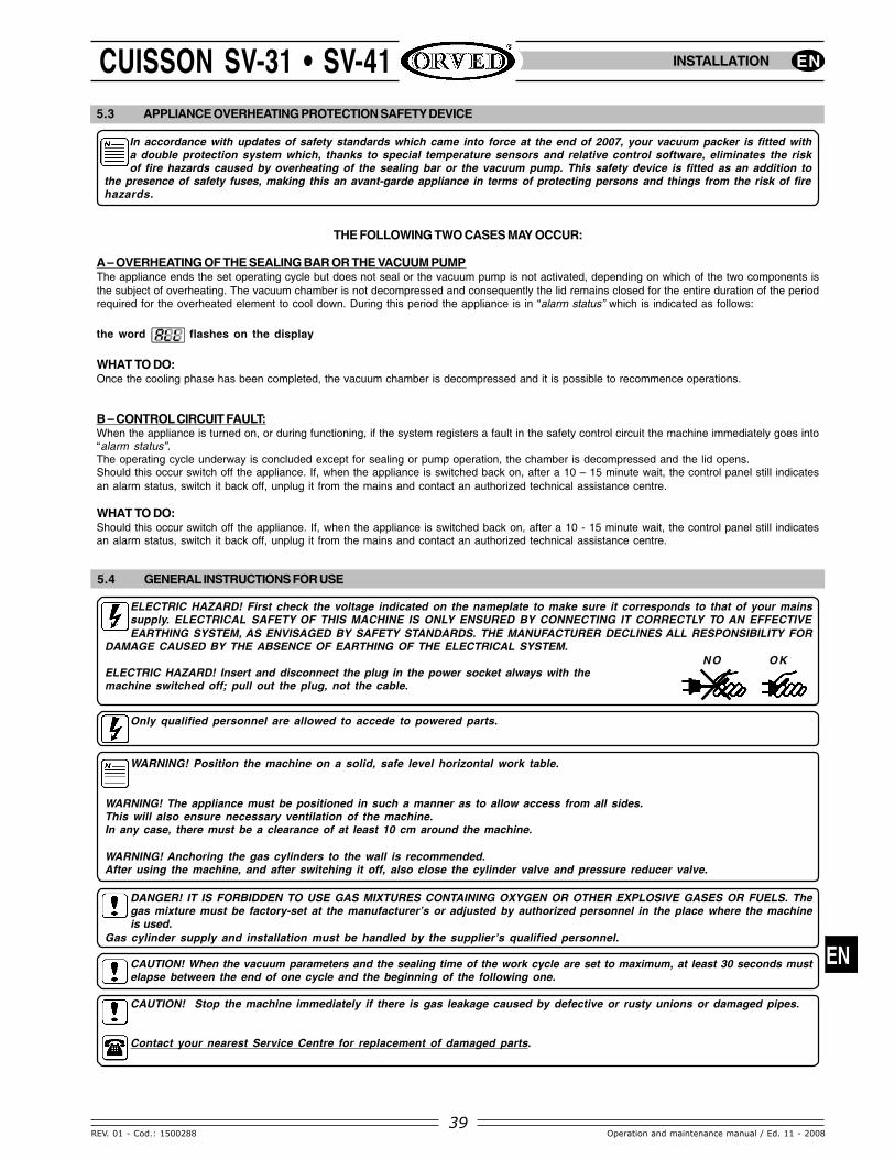
5.3 APPLIANCE OVERHEATING PROTECTION SAFETY DEVICE
In accordance with updates of safety standards which came into force at the end of 2007, your vacuum packer is fitted witha double protection system which, thanks to special temperature sensors and relative control software, eliminates the riskof fire hazards caused by overheating of the sealing bar or the vacuum pump. This safety device is fitted as an addition to
the presence of safety fuses, making this an avant-garde appliance in terms of protecting persons and things from the risk of firehazards.
THE FOLLOWING TWO CASES MAY OCCUR:
A – OVERHEATING OF THE SEALING BAR OR THE VACUUM PUMPThe appliance ends the set operating cycle but does not seal or the vacuum pump is not activated, depending on which of the two components isthe subject of overheating. The vacuum chamber is not decompressed and consequently the lid remains closed for the entire duration of the periodrequired for the overheated element to cool down. During this period the appliance is in “alarm status” which is indicated as follows:
the word flashes on the display
WHAT TO DO:Once the cooling phase has been completed, the vacuum chamber is decompressed and it is possible to recommence operations.
B – CONTROL CIRCUIT FAULT:When the appliance is turned on, or during functioning, if the system registers a fault in the safety control circuit the machine immediately goes into“alarm status”.The operating cycle underway is concluded except for sealing or pump operation, the chamber is decompressed and the lid opens.Should this occur switch off the appliance. If, when the appliance is switched back on, after a 10 – 15 minute wait, the control panel still indicatesan alarm status, switch it back off, unplug it from the mains and contact an authorized technical assistance centre.
WHAT TO DO:Should this occur switch off the appliance. If, when the appliance is switched back on, after a 10 - 15 minute wait, the control panel still indicatesan alarm status, switch it back off, unplug it from the mains and contact an authorized technical assistance centre.
NO OK
5.4 GENERAL INSTRUCTIONS FOR USE
ELECTRIC HAZARD! First check the voltage indicated on the nameplate to make sure it corresponds to that of your mainssupply. ELECTRICAL SAFETY OF THIS MACHINE IS ONLY ENSURED BY CONNECTING IT CORRECTLY TO AN EFFECTIVEEARTHING SYSTEM, AS ENVISAGED BY SAFETY STANDARDS. THE MANUFACTURER DECLINES ALL RESPONSIBILITY FOR
DAMAGE CAUSED BY THE ABSENCE OF EARTHING OF THE ELECTRICAL SYSTEM.
ELECTRIC HAZARD! Insert and disconnect the plug in the power socket always with themachine switched off; pull out the plug, not the cable.
Only qualified personnel are allowed to accede to powered parts.
WARNING! Position the machine on a solid, safe level horizontal work table.
WARNING! The appliance must be positioned in such a manner as to allow access from all sides.This will also ensure necessary ventilation of the machine.In any case, there must be a clearance of at least 10 cm around the machine.
WARNING! Anchoring the gas cylinders to the wall is recommended.After using the machine, and after switching it off, also close the cylinder valve and pressure reducer valve.
DANGER! IT IS FORBIDDEN TO USE GAS MIXTURES CONTAINING OXYGEN OR OTHER EXPLOSIVE GASES OR FUELS. Thegas mixture must be factory-set at the manufacturer’s or adjusted by authorized personnel in the place where the machineis used.
Gas cylinder supply and installation must be handled by the supplier’s qualified personnel.
CAUTION! When the vacuum parameters and the sealing time of the work cycle are set to maximum, at least 30 seconds mustelapse between the end of one cycle and the beginning of the following one.
CAUTION! Stop the machine immediately if there is gas leakage caused by defective or rusty unions or damaged pipes.
Contact your nearest Service Centre for replacement of damaged parts.

EN
40
EN
REV. 01 - Cod.: 1500288Operation and maintenance manual / Ed. 11 - 2008
CUISSON SV-31 • SV-41INSTALLATION
WARNING! THE PUMP OIL MUST BE CHANGED PERIODICALLY; THE FREQUENCY OF OIL CHANGES INCREASESPROPORTIONALLY WITH THE WORK LOAD THE APPLIANCE IS SUBJECTED TO. THE OIL MUST BE CHANGED EVERY 20,000FUNCTIONING CYCLES (EQUAL TO APPROXIMATELY 100 SERVICE HOURS SV-41) OR 12,500 CYCLES (SV-31). THE OIL
FILTER (A - Fig. 1) MUST ALSO BE CHANGED EVERY TWO OIL CHANGES.The frequency of oil and filter changes increases when liquid or damp products are dealt with on a regular basis. It is alsoimportant to change the oil if the appliance has not been used for a period of one month or more. If the oil appears whitish andcloudy or dark and transparent it means respectively, that the oil has been contaminated by liquids/ humidity or is old.The control panel is equipped with a signalling system to indicate when an oil change is due: once the appliance has executed20,000 work cycles (SV-41) or 12,500 cycles (SV-31) an ‘oil alarm’ signal will appear on the display at every start-up and at the endof each cycle. The number of cycles which have been executed can be called up on the display at any time using the buttons onthe control panel (See pag. 41).
CAUTION! As the sealing bar reaches very high temperatures, avoid touching it after sealing bags. (Fig. 2).
WARNING! Do not remove the Teflon cover on the sealing bars; do not use knives or other sharp tools to remove residue fromthe sealing bar: always wait for the bars to cool down before using blunt tools.
WARNING! Clean the machine thoroughly after use; clean the Plexiglas lid using a damp cloth, never use detergents or solvents.Use any special product available on the market for cleaning the stainless steel parts. Do not use jets of water or steam as this candamage the machine’s electrical equipment.
WARNING! When you wish to use only one of the daters, it is advisable to remove the one not in use by lifting it off its support;this will avoid unnecessary wear on the stamp (Fig. 3).
For all problems (defective working or technical assistance) please contact our Customer Service.
•
A
SV-41SV-31Fig. 1
Fig. 2
Fig. 3
WARNING! To avoid increase in oil density which could affectregular working of the pump, make sure that the environmental
temperature never falls below 12°C.
WARNING! The pump oil must be checked every time the machine isused through the level glass provided on the side of the machine’s rearpanel (Before each start up). The oil level must be between the MINIMUMand MAXIMUM level.The oil must be golden coloured and clear.
EN
41
EN
REV. 01 - Cod.: 1500288 Operation and maintenance manual / Ed. 11 - 2008
CUISSON SV-31 • SV-41
• • • •
2 10
• • • • • ••
1 7
6 9
5 83 4
11•
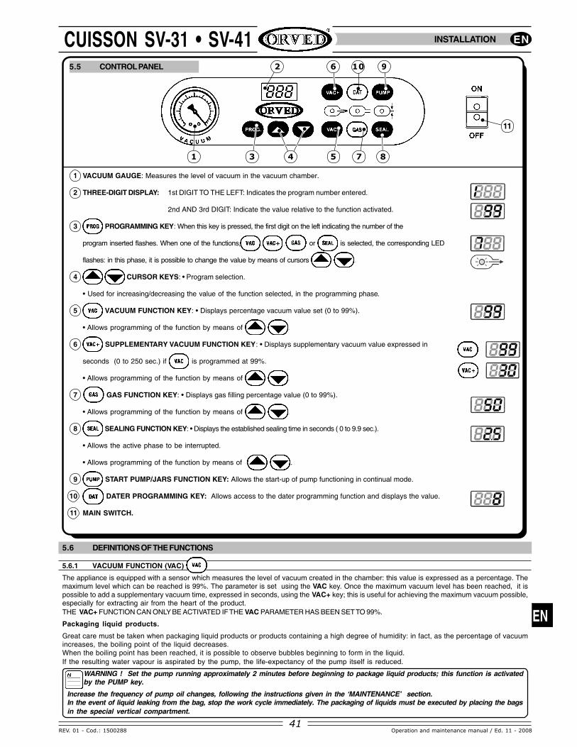
1 VACUUM GAUGE: Measures the level of vacuum in the vacuum chamber.
2 THREE-DIGIT DISPLAY: 1st DIGIT TO THE LEFT: Indicates the program number entered.
2nd AND 3rd DIGIT: Indicate the value relative to the function activated.
3 PROGRAMMING KEY: When this key is pressed, the first digit on the left indicating the number of the
program inserted flashes. When one of the functions, , , or is selected, the corresponding LED
flashes: in this phase, it is possible to change the value by means of cursors .
4 CURSOR KEYS: • Program selection.
• Used for increasing/decreasing the value of the function selected, in the programming phase.
5 VACUUM FUNCTION KEY: • Displays percentage vacuum value set (0 to 99%).
• Allows programming of the function by means of .
6 SUPPLEMENTARY VACUUM FUNCTION KEY: • Displays supplementary vacuum value expressed in
seconds (0 to 250 sec.) if is programmed at 99%.
• Allows programming of the function by means of .
7 GAS FUNCTION KEY: • Displays gas filling percentage value (0 to 99%).
• Allows programming of the function by means of .
8 SEALING FUNCTION KEY: • Displays the established sealing time in seconds ( 0 to 9.9 sec.).
• Allows the active phase to be interrupted.
• Allows programming of the function by means of .
9 START PUMP/JARS FUNCTION KEY: Allows the start-up of pump functioning in continual mode.
10 DATER PROGRAMMING KEY: Allows access to the dater programming function and displays the value.
11 MAIN SWITCH.
INSTALLATION
5.5 CONTROL PANEL
5.6 DEFINITIONS OF THE FUNCTIONS
5.6.1 VACUUM FUNCTION (VAC)
The appliance is equipped with a sensor which measures the level of vacuum created in the chamber: this value is expressed as a percentage. Themaximum level which can be reached is 99%. The parameter is set using the VAC key. Once the maximum vacuum level has been reached, it ispossible to add a supplementary vacuum time, expressed in seconds, using the VAC+ key; this is useful for achieving the maximum vacuum possible,especially for extracting air from the heart of the product.THE VAC+ FUNCTION CAN ONLY BE ACTIVATED IF THE VAC PARAMETER HAS BEEN SET TO 99%.
Packaging liquid products.
Great care must be taken when packaging liquid products or products containing a high degree of humidity: in fact, as the percentage of vacuumincreases, the boiling point of the liquid decreases.When the boiling point has been reached, it is possible to observe bubbles beginning to form in the liquid.If the resulting water vapour is aspirated by the pump, the life-expectancy of the pump itself is reduced.
WARNING ! Set the pump running approximately 2 minutes before beginning to package liquid products; this function is activatedby the PUMP key.
Increase the frequency of pump oil changes, following the instructions given in the ‘MAINTENANCE’ section.In the event of liquid leaking from the bag, stop the work cycle immediately. The packaging of liquids must be executed by placing the bagsin the special vertical compartment.

EN
42
EN
REV. 01 - Cod.: 1500288Operation and maintenance manual / Ed. 11 - 2008
CUISSON SV-31 • SV-415.6.2 VAC+ FUNCTION
Once maximum vacuum as been obtained, a supplementary vacuum value (VAC+) can be set between 0 - 250 seconds; for normal applications,a (VAC+) value between 3 and 5 seconds provides a final pressure of approximately 2 mbar. For certain applications, where a vacuum approachingthe absolute value is required, the (VAC+) function can be set between 15 and 30 seconds. For specific applications involving vacuum pack cooking,where air must be removed from the heart of the product, this value can be increased to up to 250 seconds.
5.6.3 GAS FUNCTION
The GAS option is for packaging delicate products to prevent them from being crushed by the difference in pressure. To compensate for thisdifference in pressure, the air is substituted by a controlled mixture of antioxidant gases, usually made up of 30% carbon dioxide and 60% nitrogen.It also allows antioxidant gas mixtures to be used which help to prolong the shelf-life of the product. When choosing a gas mixture, consult the relativebrochures issued by the best gas producing companies.The maximum percentage of gas allowed is 60%. This percentage refers to the volume of the chamber occupied by the gas. If the value exceeds60%, the pressure applied by the sealing bar on the bag may not be sufficient and hence sealing could be imperfect. If the lid lifts during the cycle,reduce the gas injection time. The length of the bag must be such that the opening (A) can be inserted in the dater (B), so that the bag itself is heldfast during the gas injection phase.
5.6.4 SEAL FUNCTION
Once the vacuum operation has been completed and any gas injection carried out, the appliance proceeds to seal the bag using the relative sealingbar (C) equipped with an electric resistance. Sealing times vary depending on the quality of the bags, room temperature and the quantity of work tobe carried out. The seal line on the bag must always be uniform, distinct and without any melting. Set a sealing time which is suitable to the thicknessof the bag between approximately 2 and 4 seconds.
5.6.5 DATE FUNCTION
The appliance is equipped with two daters (D) for heat printing the date (E) and a 4-digit batch number (F) on the package. Printing times varybetween 6 and 9 seconds depending on the thickness of the bag. The date and batch number are set manually by extracting the stamp holder (G)from the support (H).
5.6.6 PUMP / JARS FUNCTION
This function is used for preheating the pump before executing particularly demanding work, in order to improve performance and prolong the life-expectancy of the pump. Furthermore, this function can be used for carrying out packaging on the outside of the appliance (Fig. 1), using embossedbags with a length exceeding the maximum length specified for the dimensions of the vacuum chamber (JARS function).
•
•
H
•
•
F E
G
D
•
•
•
C
A
B
Fig. 1
USING THE APPLIANCE

EN
43
EN
REV. 01 - Cod.: 1500288 Operation and maintenance manual / Ed. 11 - 2008
CUISSON SV-31 • SV-41
Fig. 3
Fig. 4
Fig. 5
•F
G
•
•
2/3
D
E
•F
G
•
E
•
D2/3
•B
•A
Fig. 2
•
C
•H
USING THE APPLIANCE
6. USING THE MACHINE
6.1 PREPARATION
WARNING! Maximum vacuum can only be achieved with dry, cold products and decreases if there is an increase in humidityin the product or in the vacuum chamber. Soft products may be damaged by the effects of compression applied by the bagon completion of the cycle. The bag format must be selected depending on the expected shelf-life of the product, its volume,
and in the case of liquid products, its density.
PRELIMINARY CALIBRATION
When used for the first time, the vacuum sensor must becalibrated according to the atmospheric pressure(depending on the altitude of the place), as follows:
• Switch On the machine keeping the key pressed
simultaneously. The display shows .
• Lower the lid (H) with both hands, pressing the cornersslightly. The machine will start calibration which will endautomatically after about two minutes with air returning tothe chamber and consequent opening of the lid.
WARNING! The procedure must be repeated only if themachine is moved to a place at a different altitude.
6.1.2. USING BAGS IN THE HORIZONTAL POSITION
1) Lower the lid securing device (A - Fig. 2): the cave’s Plexiglas lid (B)opens.
2) Place all the shelves in the vertical compartment (C) and position themaximum number of shelves (D) that the chamber can hold in relation tothe product to be packaged.
3) Select a bag which is suitable for the product to be packaged (theproduct must fill approximately 2/3 of the bag’s serviceable volume).Place the bag containing the product to be packaged inside the vacuumchamber, ensuring it is lying over the sealing bar (E) and the daterstamp (F). If the GAS function is activated, ensure that the nozzle (G)is inside the bag. Two bags can be packaged simultaneously (Fig. 3) orone single bag at a time (Fig. 4), in this case, it is recommended toremove the dater which is not being used (Fig. 5).

EN
44
EN
REV. 01 - Cod.: 1500288Operation and maintenance manual / Ed. 11 - 2008
CUISSON SV-31 • SV-41
Fig. 2
•
3/4 H
E
BAG
•
C
•B
•
A
•
C D
•F
•
E
Fig. 1
USING THE APPLIANCE
6.1.3. USING BAGS IN THE VERTICAL POSITION
1) Lower the lid securing device (A- Fig.1): the dome’s Plexiglas lid (B) opens.
2) Position the shelves (C) in the vertical compartment, depending on the volume occupied by the bag; the remaining shelves (D) can be placed inthe horizontal compartment of the vacuum chamber.
3) Packaging of bags containing liquid products:The vertical compartment can be used for packaging up to 5 litres of liquid product at a time: in this case the bag used must be wide enough tofill the entire width of the compartment. The level of the liquid product must not exceed 3/4 of the compartment’s height (H). The remaining part ofthe bag must protrude from the compartment enough to ensure that the opening of the bag itself can be inserted in the dater (E). For smaller bagsposition the shelves (C) in such a way as to be able to insert the bag opening in the dater (E - Fig. 1).It is possible to package one bag at a time (Fig. 1) or two bags simultaneously; or a single large-format bag (Fig. 2); in this case it is recommendedto remove the dater which is not being used (F).
EN
45
EN
REV. 01 - Cod.: 1500288 Operation and maintenance manual / Ed. 11 - 2008
CUISSON SV-31 • SV-41
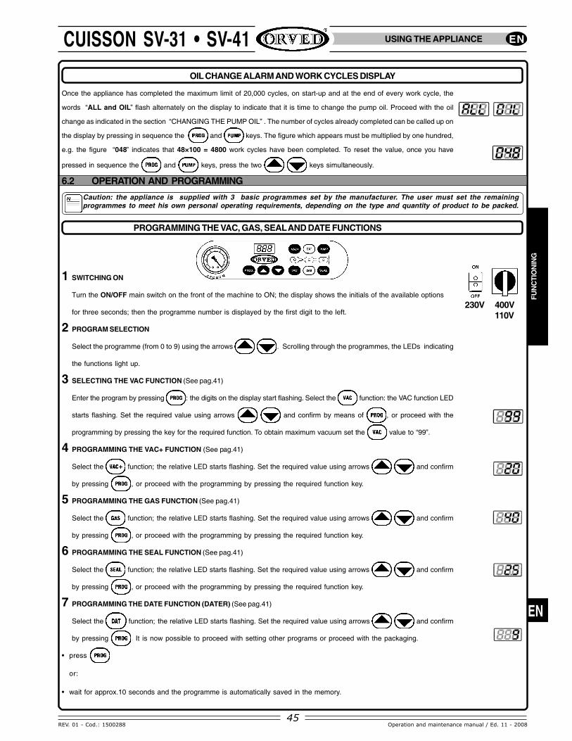
OIL CHANGE ALARM AND WORK CYCLES DISPLAY
400V110V
Caution: the appliance is supplied with 3 basic programmes set by the manufacturer. The user must set the remainingprogrammes to meet his own personal operating requirements, depending on the type and quantity of product to be packed.
230V
USING THE APPLIANCE
FUN
CTI
ON
ING
Once the appliance has completed the maximum limit of 20,000 cycles, on start-up and at the end of every work cycle, the
words “ALL and OIL” flash alternately on the display to indicate that it is time to change the pump oil. Proceed with the oil
change as indicated in the section “CHANGING THE PUMP OIL” . The number of cycles already completed can be called up on
the display by pressing in sequence the and keys. The figure which appears must be multiplied by one hundred,
e.g. the figure “048” indicates that 48×100 = 4800 work cycles have been completed. To reset the value, once you have
pressed in sequence the and keys, press the two keys simultaneously.
6.2 OPERATION AND PROGRAMMING
PROGRAMMING THE VAC, GAS, SEAL AND DATE FUNCTIONS
1 SWITCHING ON
Turn the ON/OFF main switch on the front of the machine to ON; the display shows the initials of the available options
for three seconds; then the programme number is displayed by the first digit to the left.
2 PROGRAM SELECTION
Select the programme (from 0 to 9) using the arrows . Scrolling through the programmes, the LEDs indicating
the functions light up.
3 SELECTING THE VAC FUNCTION (See pag.41)
Enter the program by pressing : the digits on the display start flashing. Select the function: the VAC function LED
starts flashing. Set the required value using arrows and confirm by means of , or proceed with the
programming by pressing the key for the required function. To obtain maximum vacuum set the value to “99”.
4 PROGRAMMING THE VAC+ FUNCTION (See pag.41)
Select the function; the relative LED starts flashing. Set the required value using arrows and confirm
by pressing , or proceed with the programming by pressing the required function key.
5 PROGRAMMING THE GAS FUNCTION (See pag.41)
Select the function; the relative LED starts flashing. Set the required value using arrows and confirm
by pressing , or proceed with the programming by pressing the required function key.
6 PROGRAMMING THE SEAL FUNCTION (See pag.41)
Select the function; the relative LED starts flashing. Set the required value using arrows and confirm
by pressing , or proceed with the programming by pressing the required function key.
7 PROGRAMMING THE DATE FUNCTION (DATER) (See pag.41)
Select the function; the relative LED starts flashing. Set the required value using arrows and confirm
by pressing . It is now possible to proceed with setting other programs or proceed with the packaging.
• press
or:
• wait for approx.10 seconds and the programme is automatically saved in the memory.

EN
46
EN
REV. 01 - Cod.: 1500288Operation and maintenance manual / Ed. 11 - 2008
CUISSON SV-31 • SV-41
•
20 mm.A
•
BFU
NC
TION
ING
USING THE APPLIANCE
INTERRUPTING THE WORK CYCLE
Activate the button; the work cycle can be interrupted at any moment; interruption is immediate with air re-entering the chamber. The work
cycle can also be interrupted by means of the ON/OFF main switch: when the appliance is switched off, the cycle is interrupted but air does not
return to the suction cup: the lid therefore remains closed.
When the appliance is switched on again, the cycle is reset, air returns to the chamber and the lid opens.
ACTIVATING AND DEACTIVATING THE GAS FUNCTION
ACTIVATION
- Press the key.
- Press the key, the display flashes alternately with “GAS” or “SI”; a few seconds later, the value set is displayed.
- Change the value using the cursor keys and/or confirm by means of ; the LED remains On and the function is activated.
DEACTIVATION
- Press the key.
- Press the key, the set gas percentage appears on the display.
- Press the key again; the words “GAS” and “NO” flash alternately on the display; a few seconds later, the LED and the function are
deactivated.
PROGRAMMING THE “PUMP” FUNCTIONFOR VACUUM PACKING EMBOSSED BAGS OUTSIDE THE VACUUM CHAMBER
1 Turn on the appliance and set the sealing value in accordance with the thickness of the bag to be used; deactivate the GAS function.
2 Press the key; the words “JAR” and “SI” flash alternately on the display. Position the bag about 20mm beyond sealing bar (A), then start
the cycle by lowering the lid (B).
3 When vacuum formation has been completed inside the bag, press . The appliance will proceed to the bag sealing phase. The cycle ends
when air returns to the chamber and the lid opens.
8 WORK CYCLE START-UP : Lower the lid using both hands pressing it down lighlty at the corners. The appliance will start the work cycle
according to the set parameters.
9 WORK CYCLE END: The appliance automatically ends the cycle after the sealing bar phase and re-entry of air in the chamber with consequent
opening of the lid. Remove the packed product and check the seal; it must be uniform, well marked and without melted points. Adjust the preset
values, if necessary, and proceed with the second cycle.

EN
47
EN
REV. 01 - Cod.: 1500288 Operation and maintenance manual / Ed. 11 - 2008
CUISSON SV-31 • SV-41
•A
•
•E
•
D
•C• B
VACUUM PACKING GOODS IN A RIGID CONTAINER (VACUUM BOX)
USING THE APPLIANCE
1 Switch on the appliance and zero the sealing time.
2 Deactivate the GAS function and remove both the dater stamp holders (A).
3 Prepare the lid of the container equipped with a valve by slightly unscrewing
the valve sealing ring (B) so that the plug it contains (C) is mobile.
4 Position the shelves (D) to suit the dimensions of the container (vacuum box).
5 Programme the functions and the functions if required.
6 WORK CYCLE START-UP:
Lower the lid (E) using both hands, pressing it down lightly at the corners.
The appliance will start the work cycle according to the set parameters.
7 WORK CYCLE END:
The lid opens automatically when the cycle ends. Remove the container and
quickly tighten the valve sealing ring (B) to stop air from entering the container.
WARNINGS!
• SELECT BAGS OF A FORMAT AND THICKNESS WHICH BEST SUIT THE SIZE, RIGIDITY AND ANGULARITY OF THE PRODUCT.WHEN USING THE VERTICAL COMPARTMENT, THE BAG MUST BE BIG ENOUGH TO ENSURE THAT THE OPENING CAN BEINSERTED IN THE DATER.
• WHEN THE GAS FUNCTION IS ACTIVATED, THE LENGTH OF THE BAG MUST BE SUFFICIENT TO ENSURE THAT THE OPENINGCAN BE INSERTED IN THE DATER; THIS PREVENTS THE BAG FROM MOVING AWAY FROM THE SEALING BAR WHEN THE GASIS INJECTED.
• CARRY OUT PRELIMINARY SETTINGS BEFORE STARTING THE APPLIANCE.
• WHEN VACUUM PACKING A RIGID CONTAINER PLACED IN THE VACUUM CHAMBER, ZERO THE SEALING TIME, DEACTIVATETHE GAS FUNCTION AND REMOVE THE DATER STAMP HOLDERS FROM THEIR SUPPORTS.
• THE WORK CYCLE CAN BE STOPPED AT ANY MOMENT BY PUSHING THE KEY.
• IF THE LID OPENS DURING THE GAS FLUSHING CYCLE, REDUCE THE GAS FLUSHING TIME.
• WHEN CARRYING OUT NUMEROUS SUCCESSIVE WORK CYCLES, REDUCE THE SEALING TIME TO AVOID THE APPEARANCE OFMELTING POINTS ALONG THE BAG’S SEALING LINE.
• FOR A CORRECT CHOICE OF THE GAS MIXTURE TO BE USED DEPENDING ON THE FOODS TO BE PRESERVED, REFER TO THELEAFLETS DISTRIBUTED BY THE GAS PRODUCERS.
• USE OF GAS MIXTURES CONTAINING OXYGEN OR OTHER EXPLOSIVE GASES IS SEVERELY PROHIBITED.
• AVOID LIQUIDS FROM LEAKING OUT OF BAGS BY SELECTING A BAG FORMAT WHICH IS SUITABLE FOR THE VOLUME OFPRODUCT TO BE PACKAGED. THE HIGHER THE DENSITY OF THE PRODUCT (SAUCES, DRESSINGS ETC.), THE LOWER THEVOLUME WHICH CAN BE PACKAGED . (MAX. 5 LT FOR PRODUCTS WITH A DENSITY SIMILAR TO THAT OF WATER, MAX. 4 LTFOR SAUCES AND DRESSINGS).
• IF THE APPLIANCE OVERHEATS IT MAY ASSUME ALARM STATUS AS SHOWN BY THE FLASHING MESSAGE “ALL”. FOLLOWTHE STEPS ILLUSTRATED ON PARAGRAPH 5.3.

EN
48
EN
REV. 01 - Cod.: 1500288Operation and maintenance manual / Ed. 11 - 2008
CUISSON SV-31 • SV-41
Before each start up
Weekly
Every 12,500 operating cy-cles (approx. 50 hours forMod. SV-31).
Every 20,000 operating cy-cles (approx. 100 hours forMod. SV-41).
Every two oil changes
Every 6 months
Check the oil colour and level; top up the level,or change it completely if the colour is dark orwhitish.
Check to make sure it is intact, replace ifdamaged (Contact a specialist Service Centre).
Check to make sure it is intact ; if cracks orstreaks are present, contact Customer servicefor replacement.
Check to make sure they are inserted properlyin their seats; replace if damaged.
Clean to remove impurities, oil and grease.
Clean the upper part with a damp cloth.
Run the pump for about 30 minutes (using thePump function) to allow removal of water fromthe pump oil.
Change the pump oil(call a specialist Service Centre).
Change the pump exhaust filter (A)(call a specialist Service Centre).
Change the pump oil.(call a specialist Service Centre).
Pump
Power cable
Plexiglas cover
Red siliconeand Plexiglas cover gasket
Machine and vacuum chamber
Sealing bar
Pump
Pump
Pump
Pump
FREQUENCY MACHINE PART ACTION
7.3 CARE AND CLEANING OF THE VACUUM PACKAGING MACHINE
7. MAINTENANCE
7.1 GENERAL WARNINGS
ELECTRIC HAZARD!Maintenance and/or repair operations on any of the appliance components must be done only after disconnecting the power
supplies (Disconnecting the plug from the mains).
CAUTION!Only qualified personnel must be allowed to carry out maintenance operations or access powered parts of the machine.
ELECTRIC HAZARD!Disconnect the electric current before carrying out cleaning or maintenance.
For repairs, if necessary, contact a Service Centre authorized by the manufacturer. Use and demand genuine spare parts.
7.2 PROGRAMMED MAINTENANCE
MAINTENANCE
•
AELECTRIC HAZARD!Danger of electric shock ! Remove the machine plug fromthe power socket. Do not use water or steam jets.
DANGER! Danger of burns: if alcohol-based or inflammabledisinfectant products are used, ventilate the area. Do not usenaked flames near the machine! Do not smoke!
CAUTION! Danger of injury! Use personal protectiveequipment. Do not use caustic products, acids or aggres-sive products such as muriatic acid. Read the instructionson the detergent product or disinfectant pack carefully.
WARNINGS! Use alcohol-based disinfectants.The machine must be cleaned and disinfected every timeafter use.
EN
49
EN
REV. 01 - Cod.: 1500288 Operation and maintenance manual / Ed. 11 - 2008
CUISSON SV-31 • SV-41
•
E
•
•
•
B
Fig. 1 Fig. 2
A
Fig. 3 Fig. 4
•
C
•D
F
MAINTENANCE
7.3.1 CLEANING THE PLEXIGLAS LID
• Wipe using a cloth made damp with water or a detergent specially meant for Plexiglas (maximum temperature 40°C).
• Do not use other types of detergents.
• Dry the lid thoroughly.
7.3.2 CLEANING THE SEALING BARS
CAUTION!Burning hazard! Do not start cleaning operations when the sealing bars are hot.
• Clean the upper part of the sealing bar using a damp cloth (water only).
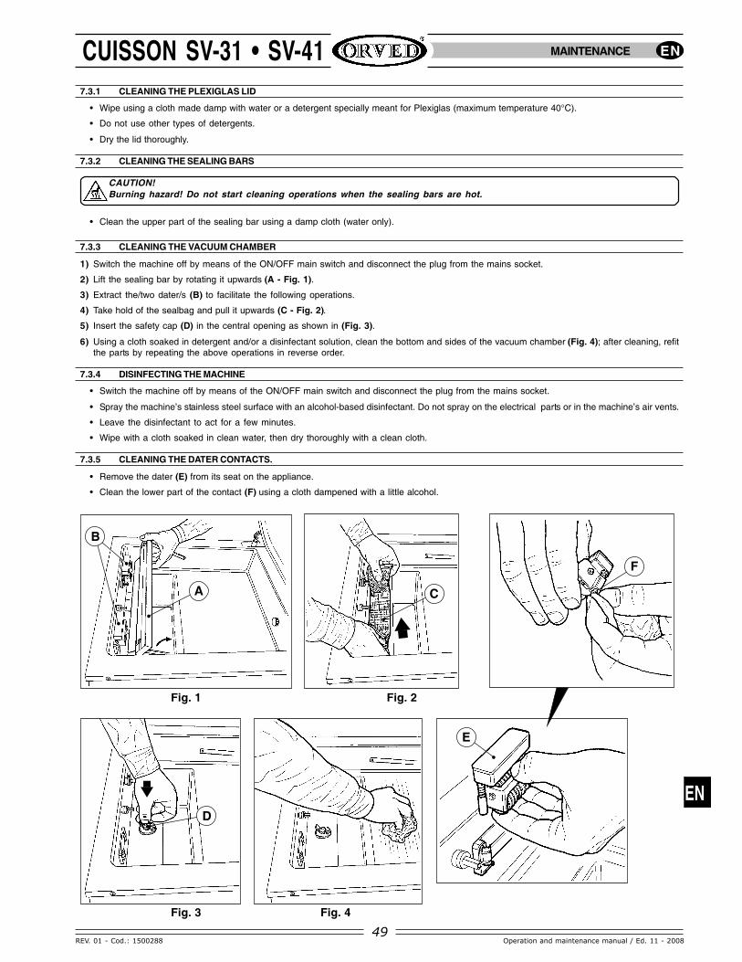
7.3.3 CLEANING THE VACUUM CHAMBER
1) Switch the machine off by means of the ON/OFF main switch and disconnect the plug from the mains socket.
2) Lift the sealing bar by rotating it upwards (A - Fig. 1).
3) Extract the/two dater/s (B) to facilitate the following operations.
4) Take hold of the sealbag and pull it upwards (C - Fig. 2).
5) Insert the safety cap (D) in the central opening as shown in (Fig. 3).
6) Using a cloth soaked in detergent and/or a disinfectant solution, clean the bottom and sides of the vacuum chamber (Fig. 4); after cleaning, refitthe parts by repeating the above operations in reverse order.
7.3.4 DISINFECTING THE MACHINE
• Switch the machine off by means of the ON/OFF main switch and disconnect the plug from the mains socket.
• Spray the machine’s stainless steel surface with an alcohol-based disinfectant. Do not spray on the electrical parts or in the machine’s air vents.
• Leave the disinfectant to act for a few minutes.
• Wipe with a cloth soaked in clean water, then dry thoroughly with a clean cloth.
7.3.5 CLEANING THE DATER CONTACTS.
• Remove the dater (E) from its seat on the appliance.
• Clean the lower part of the contact (F) using a cloth dampened with a little alcohol.

EN
50
EN
REV. 01 - Cod.: 1500288Operation and maintenance manual / Ed. 11 - 2008
CUISSON SV-31 • SV-41
Fig. 1 Fig. 2
7.4 ROUTINE MAINTENANCE
7.4.1 REPLACING THE SEALING BAR COVER TEFLON BAND
After a long period of use, a black mark starts appearing on the sealing bar cover Teflon band, so it must be replaced.To do so, proceed as follows:1) Switch the machine off by means of the ON/OFF main switch and disconnect
the plug from the mains socket.2) Lift the sealing bar by rotating it upwards (A - Fig. 1).3) Detach the brown Teflon cover (Fig. 2).4) Wipe the sealing bar with alcohol (Fig. 3).5) Fit a new band (Fig. 4) cutting the excess length at the two ends (Fig. 5).
CAUTION!Burning hazard! Do not start Teflon band replacement when thesealing bars are hot.
•A
MAINTENANCE
ALCOHOL
Fig. 3 Fig. 4 Fig. 5
SV-31
SV-41
•
A
•
B
B•
•
C
•
C
D••D
•D
7.4.2 CHANGING THE PUMP OIL
WARNING: This operation must be carried out by qualified personnel.
For correct oil change, disconnect the pump from the power supply. The pump must be at normal functioning temperature with the vacuum chamberat normal atmospheric pressure (no vacuum).
1) Run the pump for about 10 minutes so that the oil becomes fluid, by activating the (PUMP) function.2) Stop the pump by pressing SEAL.3) Switch off the machine using the ON/OFF main switch and remove the plug from the power socket.4) Unscrew the oil filling screw as follows:5) Remove the stainless steel side (A), then unscrew screw (B) using an Allen key;6) Get hold of a suitable container for collecting the displaced oil approximately 0.3 liters (SV-31) and 1.2 liters (SV-41) and unscrew the drainage
plug (C) located on the lower section of the pump. Allow the oil to drain out for approximately 10 minutes.7) Refit the oil drainage plug (C) and top up with oil type ORV 40 for (SV-31) or ORV 60 for (SV-41) until it reaches a level which just exceeds
the halfway point on the pump inspection glass (D).

EN
51
EN
REV. 01 - Cod.: 1500288 Operation and maintenance manual / Ed. 11 - 2008
CUISSON SV-31 • SV-41
7.4.4 CHANGING THE LID GASKET AND RED SILICONE
1) Open the plexiglas lid.
2) Remove lid gasket (G) or the red silicone strip (H) and clean the seats to remove any dirt.
3) Insert the new gasket pushing it firmly into the cavity.
4) Run a loadless cycle so that the gasket fits into its seat correctly.
•
H
G
MAINTENANCE
•
A•
B
SV-41SV-31
B
•
7.4.3 CHANGING THE PUMP OIL FILTER
WARNING: This operation must be carried out by qualified personnel.
1) Remove the stainless steel side panel (A) from the appliance (SV-41).
2) Unscrew plug (B) on the pump body using pliers.
3) Remove the filter (C) from its seat.
4) Insert the new filter after checking to make sure the ’O-ring (D) is in the correct position.
5) Refit the cover by fixing spring (E) on the filter projection (F).
•
C
••
EF
•
D

EN
53
EN
REV. 01 - Cod.: 1500288 Operation and maintenance manual / Ed. 11 - 2008
CUISSON SV-31 • SV-41 MAINTENANCE
7.5 TROUBLESHOOTING
PROBLEM POSSIBLE CAUSES
Machine not working.
The appliance terminates the programmedwork cycle but without sealing the bag orwithout activating the vacuum pump.
The appliance enters “alarm status”when it is powered on. The work cyclein progress is terminated without sealingthe bag or without operation of thevacuum pump; the vacuum chamber isdepressurised and the lid reopens.
Insufficient vacuum inchamber.
Machine does not createvacuum in chamber.
PLexiglas cover does notclose.
Insufficient vacuum in bag/bag does not maintainvacuum.
Seal seam shows burns and bubbles.
Narrow irregular sealseam.
The machine does not seal.
SOLUTION
Machine Off.
No power supply.
Machine damage.
Vacuum pump or sealingtransformer overheating.
Appliance overheating.
Safety control circuit fault.
Set vacuum percentage isinsufficient.
Vacuum pump performan-ce insufficient.
Cover gasket worn.
Pressure exerted onPlexiglas cover duringappliance start upinsufficient.
Gas function activated.
Pump not working.
Cover gasket worn.
Hinges out of alignment.
Bag positioned incorrectly.
Bag perforated.
Sealing insufficient.
Bag defective.
Dirty bag open.
Bag too big or too small inrelation to product size.
Sealing time too long.
Sealing time too short.
Sealing bar connection dirty.
Sealing Bar wire broken.
Gas quantity more than 60%.
Sealing bar fuse blown.
Seal bag perforated.
Switch on the machine using the ON/OFF main switch.
Insert the plug in a socket (check the voltage!).
Check power cable to make sure it is intact.
Check fuses PF3 and PF4 on the power board to make sure they areintact and inserted correctly.
Contact a Service centre.
Wait approximately 15 or 20 minutes for the appliance to cool; atthe end of this period the vacuum chamber will be depressurisedand the work cycle can be resumed.
Switch off the appliance and then switch it on again after an intervalof between 15 and 20 minutes.
Contact an authorised service centre.
Increase the vacuum percentage up to 99%. Add supplementaryvacuum using the VAC+ key.
Check oil.
Check pump exhaust filter.
Replace cover gasket.
Lower cover with both hands, exerting more pressure.
Deactivate the gas function.
Change pump fuse PF1 on the power board.(Contact a Service Centre. )
Change the gasket.
Adjust the cover hinge.(contact a Service Centre).
Position the bag centrally in relation to the sealing bar. Ensure thebag protrudes by 20 mm over the bar. Cycle with gas activated: fixthe bag opening in the dater. Bag too small for the volume to bepackaged.
Choose a thicker bag and wrap the product with cling film or soft paper.
Increase the sealing time.
Change the bag.
Use a new bag and avoid smearing the opening with oil, grease, etc.
Choose a bag size suitable for product dimensions.
Decrease the sealing time.
Increase the sealing time.
clean the contacts with contact-spray.
Change wire (Contact a Service Centre).
Reduce gas percentage.
Change PF2 fuse on power board.
Change seal bag.

EN
54
EN
REV. 01 - Cod.: 1500288Operation and maintenance manual / Ed. 11 - 2008
CUISSON SV-31 • SV-41
PROBLEM POSSIBLE CAUSES
Date and numbering areillegible
Poor sealing.
Gas quantity in bagsinsufficient.
Lid opens during GAScycle.
Vacuum not created incontainers.
Timer fuse cut out.
Insufficient printing time.
Dirty contact.
Sealing bar dirty.
Sealing time insufficientfor bag basic weight.
Teflon cover worn.
Red silicone worn.
Gas flushing timeinsufficient.
Gas cylinder pressureinsufficient.
Gas nozzle not inserted inbag mouth.
Cylinder valve or pressurereducer closed.
Gas percentage too high.
Cover not placed correctly.
SOLUTION
Replace the timer fuse. (PFT - pag. 52)
Increase the printing time using the PROG and DAT keys.
Clean the contacts and the guide pins (SEE FIG. PAG. 49).
Clean sealing bar.
Increase sealing time using
Change Teflon cover.
Change red silicone.
Increase gas percentage
Adjust pressure on cylinder reducer to 1 bar.
Reposition bag by inserting gas nozzle in the bag opening.
Open cylinder valves and adjust pressure reducer to 1.0 bar.
Reduce gas percentage
Reposition then create vacuum by pressing slightly on the lid.
MAINTENANCE
8. DISPOSAL OF THE MACHINE AND ITS PARTS
For disposing of the VACUUM PACKAGING MACHINE or its components, do not dump these in city waste bins: scrappedappliances are not useless waste!
The machine does not contain components that are hazardous for humans or the environment; it is made of materials that can be recycled completelyor disposed of normally.
For disposal operations, contact specialist, authorized Companies. Before starting dismantling operations, make surethere is enough clearance around the machine to carry out the operations easily.
In any case, make sure, every part of the machine is disposed off in accordance with the legislation applicable in the country of use.
8.1 DISPOSING PNEUMATIC SPRINGS
DANGER! Danger of serious injury: the pneumatic springs are loaded at about 180 bar, therefore they must not be cut ordamaged as they can burst throwing off splinters.The disposal of these parts must be done exclusively by qualified personnel.
9. SPARE PARTS: GENERAL WARNINGS
For ordering spare parts, always indicate the following data:
• MACHINE SERIAL NUMBER (see CE plate on the back of the machine)
• SPARE PART CODE (see Table)
10. THE MANUFACTURER
Thank you for your trust.The manufacturer reserves the right to make technical and/or aesthetic modifications to our products at any moment, without any prior notice.