Embed Size (px)
Citation preview
_ _ _ _ _ _ _ - _ _ _____ _ _ _ _
-
* ' .... .. ,
PLANT OPERATIONS MANUAL* *
.,
. - . ,
.
|
O|
Volume 08 08-S-04-220 i
Ssetion 04 Revision 0
Date: 6-27-83.
CHEMISTRY INSTRUCTION
VENTILATION EXHAUST GASEOUS MONITORING SYSTEMS OPERATION
SAFETY RELATED
|
Prepared: 7[/ h[ dReviewed: Ammy
[ Technical Review / Independent Review
Approved: d&w [/[[/[]Chemis t ry/ Rad ia t ion ' Cor.t ro l S upe rint end ent
Concurrence: ///A y70- 4/et./r3Assistadt Plant Manager ' '
List of Effective Pages:
Page
ymmm . -
..t..itmp
Acts. I-II A v51
List of TCN's Incorporated: " '' '"';, ,
p
Revision TCN No. .3, dk..)J J, , di .J..,
WORD PROCESS::NG To "-
- a
8308%$ 0 pPDR6
. _ _ _ _ _ _ _ _ _ _ _ _ _ _ _ _ _ _ _ _ _ _ _ _ _ _ _ _ . _ _ _ _
., GRAND GULF NUCLEAR STATION CHEMISTRY INSTRUCTION-.
| Title V&ntilation Exhau;t Gar 4ous No.: 08-5-04-220 ;Rcvision: O Patger 1*
. . Monitoring Systems' Operation'.
.
|
1.0 PURPOSE i|'
!
To provide instructions for operating the radiological monitoring subsystemswhich monitor gaseous effluents from the Fuel Handling Area, Standby GasTreatment A and B, and the Containment, Turbine and Radwaste Buildings.
2.0 REFERENCES
2.1 GEK-73680, Process Radiation Monitoring System, Section III, June, 1979,MP&L Access Number 460000943
2.2 Eberline Instrument Corporation Technical Manuals as follows:
2.2.1 Particulate, Iodine and Noble Gas Monitor, Model SPING-4, MP&LAccess Number 460001758
2.2.2 Accident Ranoe Monitor, Model AXM-1, MP&L Access Number 460001760
{ 2.3 Applicable MP&L Calibration and Sampling Procedures
3.0 DEFINITIONSf
3.1 General Electric and Eberline Ventilation Monitoring Subsystems - The_ Vent Release Sampling and Monitoring Subsystems which continually(- sample and monitor the gases being vented through the exhaust venta from
the Fuel Handling Area SBGT A and B Containment, Turbine and RadwasteBuildings. (The SBGT monitors do not have a GE subsystem). A smallportion of the bulk gas volume is extracted by isokinetic probes and inletlines from the ventilation system just prior to discharge into theatmosphere. The representative gas sample is passed through the detectorsystems where particulates (if any) and lodines (if any) are filtered andmeasured, (particulates and iodine are measured in line by the EberlineSystem only) then passed through the noble gas detector's chambers formeasurement before being returned to the ventilation exhaust. The twosystems (General Electric and Eberline), which serve as "back up" systemsto each other, sample and monitor the same ventilation streams and providethe means by which gaseous, particulate and iodine grab samples may beobtained for analysis.
3.2 General Electric Monitoring Subsystems
3.2.1 Each subsystem continuously monitors the flow and gama radiationintensity of the ventilation exhaust gases. Particulates andiodines are continuously filtered. Although there are noprovisions for continuous monitoring of the activities collectedby the filters, the particulate and iodine filters are easilychanged-out for periodic laboratory analyses. The generalcomponents of the subsystems are:
.
m
_ _ _ _
GRAND GULF NUCLEAR STATION CHEMISTRY INSTRUCTION ,,
,
Titlas Ventilcticn Exhiunt Ga;cous No.: 08-5-04-220 Rsvision: 0. Pcge.: 2 *.
Monitoring System 2' Oparction,
.
.
Ta. Isokinetic probes and inlet lines which extend into the ' .)exhaust vents
b. Sampling panels containing exchangeable filters and thenecessary valves for regulating sample flow
c. Radiation sample chambers with 3 G-M tubes
d. Vacuum pumps
Log count rate meters (LCRMs) with trip circuitse.
f. A trip auxiliary unit
g. Two strip chart recorders with one pen for each system
3.2.2 Sample Panels - The panels from which ventilation and sample flowrate is controlled and from which grab samples (iodines andparticulates) may be obtained. The panels are identified asfollows:
a. SD17-P001.- Radwaste Building Vent
b. SD17-P002 - Containment Building Vent.
c. SD17-P003 - Fuel Handling Area Vent /
d. SD17-P004 - Turbine Building Vent
3.2.3 Radiation Monitoring Panels - The panels located in the Operations_
Control Room by which alarm setpoints may be established,continuous radiation monitoring of gaseous effluents may bemaintained, and routine radiation source checks may be performedare identified as follows:
a. P600
(1) Strip Chart Recorder,1D17-RR-R600
(a) Red Pen - Redwaste Building Ventilation
(b) Black Pen - Containment Building Ventilation
|
_ _ . _ _ . . .
GRAND GULF NUCLEAR STATION ., CHEMISTRY INSTRUCTION,
Titist Wentilctinn Exhaust G = ous Ns.: 08-5-04-220 . Revision: 0 |Paga 3.
Monitoring Systema' Opnration.
.
< %.!
'
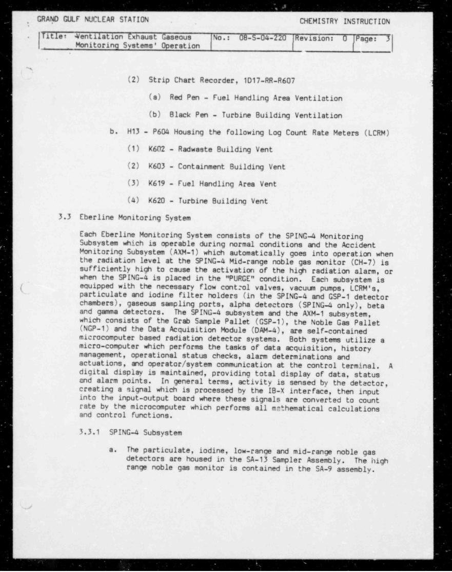
.(2) Strip Chart Recorder, 1D17-RR-R607 -
-
(a) Red Pen - Fuel Handling Area Ventilation |
(b) Black Pen - Turbine Building Ventilation1
b. H13 - P604 Housing the following Log Count Rate Meters (LCRM)
(1) K602 - Radweste Building Vent
(2) K603 - Containment Building Vent
(3) K619 - Fuel Handling Area Vent
(4) K620 - Turbine Building Vent
3.3 Eberline Monitoring Systemi
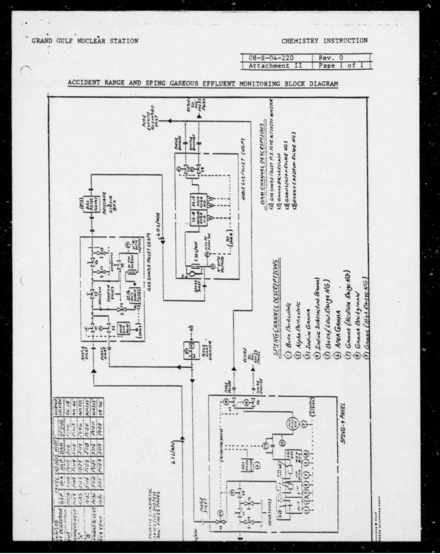
Each Eber11ne Monitoring System consists of the SPING-4 MonitoringSubsystem which is operable during normal conditions and the Accident (Monitoring Subsystem (AXM-1) which automatically goes into operation whenthe radiation level at the SPING-4 Mid-range noble gas monitor (CH-7) issufficiently high to cause the activation of the high radiation alarm, orwhen the SPING-4 is placed in the " PURGE" condition. Each subsystem is('- equipped with the necessary flow control valves, vacuum pumps, LCRM's,' particulate and iodine filter holders (in the SPING-4 and GSP-1 detector
lchambers), gaseous sampling ports, alpha detectors (SPING-4 only), beta '
and gamma detectors. The SPING-4 subsystem and the AXM-1 subsystem,which consists of the Grab Sample Pallet (GSP-1), the Noble Gas Pallet(NGP-1) and the Data Acquisition Module (DAM-4), are self-containedmicrocomputer based radiation detector systems. Both systems utilize amicro-computer which performs the tasks of data acquisition, historymanagement, operational status checks, alarm determinations andactuations, and operator / system communication at the control terminal. Adigital display is maintained, providing total display of data, statusand alarm points. In general terms, activity is sensed by the detector,creating a signal which is processed by the IB-X interface, then inputinto the input-output board where these signals are converted to count
<
rate by the microcomputer which performs all mathematical calculationsand control functions.
!
3.3.1 SPING-4 Subsystem
The particulate, iodine, low-range and mid-range noble gasa.detectors are housed in the SA-13 Sampler Assembly. The highrange noble gas monitor is contained in the SA-9 assembly.
v
GRAND GULF AICLEAR STATION CHEMISTRY INSTRUCTION,
Title Vcntilction Exhaur.t Gazeous No.: 08-5-04-220 Ravision O Page 4 '
.
Monitoring Systema' Opsrs, tion ,
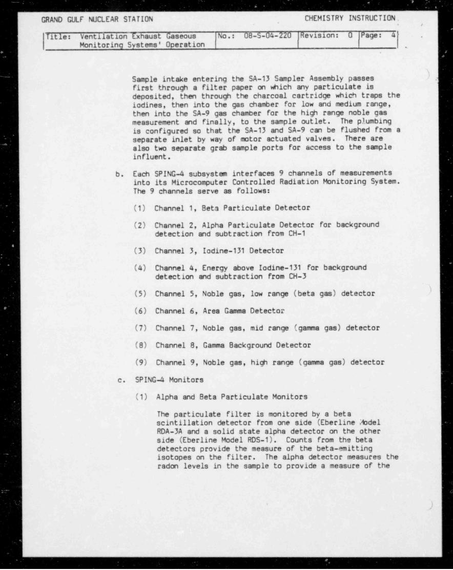
).Sample intake entering the SA-13 Sampler Assembly passesfirst through a filter paper on which any particulate isdeposited, then through the charcoal cartridge which traps thelodines, then into the gas chamber for low and medium range,then into the SA-9 gas chamber for the high range noble gasmeasurement and finally, to the sample outlet. The plumbingis configured so that the SA-13 and SA-9 can be flushed from aseparate inlet by way of motor actuated valves. There arealso two separate grab sample ports for access to the sampleinfluent.
b. Each SPING-4 subsystem interfaces 9 channels of measurementsinto its Microcomputer Controlled Radiation Monitoring System.The 9 channels serve as follows:
(1) Channel 1, Beta Particulate Detector
(2) Channel 2, Alpha Particulate Detector for backgrounddetection and subtraction from CH-1
(3) Channel 3, Iodine-131 Detector
(4) Channel 4, Energy above Iodine-131 for backgrounddetection and subtraction from CH-3
(5) Channel 5, Noble gas, low range (beta gas) detector )
(6) Channel 6, Area Gamma Detector
(7) Channel 7, Noble gas, mid range (gamma gas) detector
(8) Channel 8, Gamma Background Detector
(9) Channel 9, Noble gas, high range (gamma gas) detector
c. SPING-4 Monitors
(1) Alpha and Beta Particulate Monitors
The particulate filter is monitored by a betascintillation detector from one side (Eberline ModelRDA-3A and a solid state alpha detector on the other
side (Eberline Model RDS-1). Counts from the betadetectors provide the measure of the beta-emittingisotopes on the filter. The alpha detector measures theradon levels in the sample to provide a measure of the
.
-_
GRAND GULF NUCLEAR STATION - CHEMISTRY INSTRUCTION.,
Titla Tcntilction Exhtuat Graeous No.: 08-S-04-220 Ravision: O Pag 3: 5i *
. Monitoring Systems' Operation.
t .
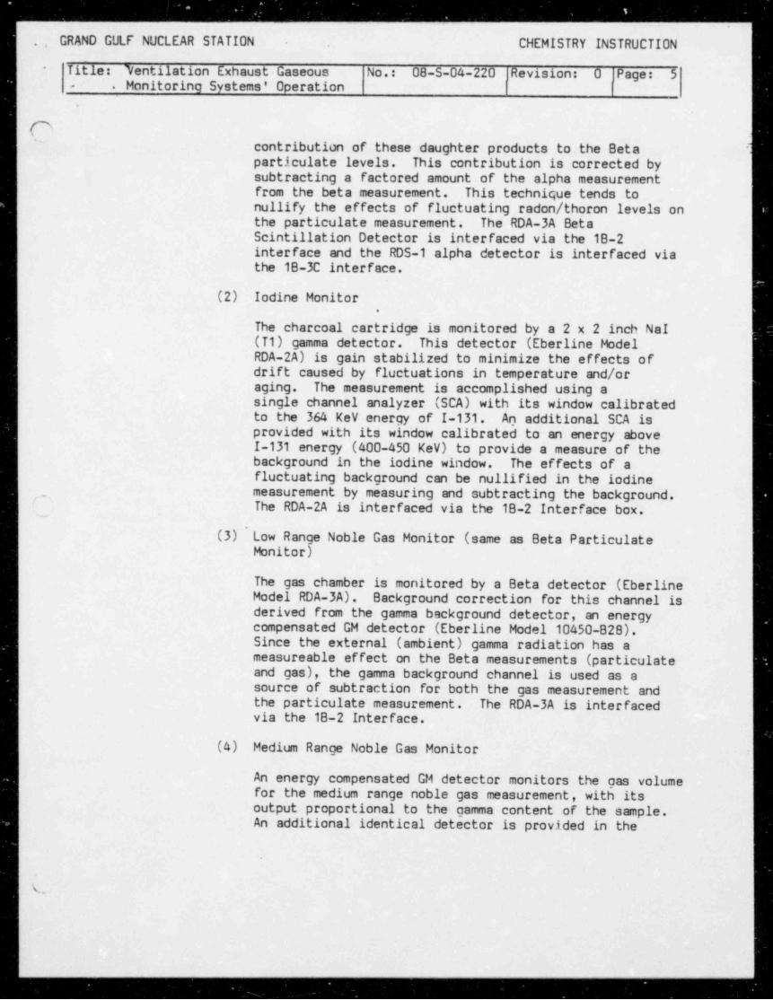
(~5 a"| contribution of these daughter products to the Beta il particulate levels. This contribution is corrected by
subtracting a factored amount of the alpha measurementfrom the beta measurement. This technique tends tonullify the effects of fluctuating radon / thoron levels onthe particulate measurement. The RDA-3A BetaScintillation Detector is interfaced via the 18-2interface and the RDS-1 alpha detector is interfaced viathe 18-3C interface.
(2) Iodine Monitor.
The charcoal cartridge is monitored by a 2 x 2 inch NaI(T1) gamma detector. This detector (Eberline ModelRDA-2A) is gain stabilized to minimize the effects ofdrift caused by fluctuations in temperature and/oraging. The measurement is accomplished using asingle channel analyzer (SCA) with its window calibratedto the 364 kev energy of I-131. An additional SCA isprovided with its window calibrated to an energy aboveI-131 energy (400-450 kev) to provide a measure of thebackground in the iodine window. The effects of afluctuating background can be nullified in the iodinemeasurement by measuring and subtracting the background./_' The RDA-2A is interfaced via the 18-2 Interface box.-
(3)' Low Range Noble Gas Monitor (same as Beta ParticulateMonitor)
The gas chamber is monitored by a Beta detector (EberlineModel RDA-3A). Background correction for this channel isderived from the gamma background detector, an energycompensated GM detector (Eberline Model 10450-828).Since the external (ambient) gamma radiation has ameasureable effect on the Beta measurements (particulateand gas), the gamma background channel is used as asource of subtraction for both the gas measurement andthe particulate measurement. The RDA-3A is interfacedvia the 18-2 Interface.
(4) Medium Range Noble Gas Monitor
An energy compensated GM detector monitors the gas volumefor the medium range noble gas measurement, with itsoutput proportional to the gamma content of the sample.An additional identical detector is provided in the
,
w'
GRAND GULF NUCLEAR STATION ,CHEMISTRY INSTRUCTION.
.
Title Vantilation Exhrust Gareous Nn.: 08-5-04-220 devisions O Pages 6 '
.
IMonitoring Systema' Oparation ,
I
'
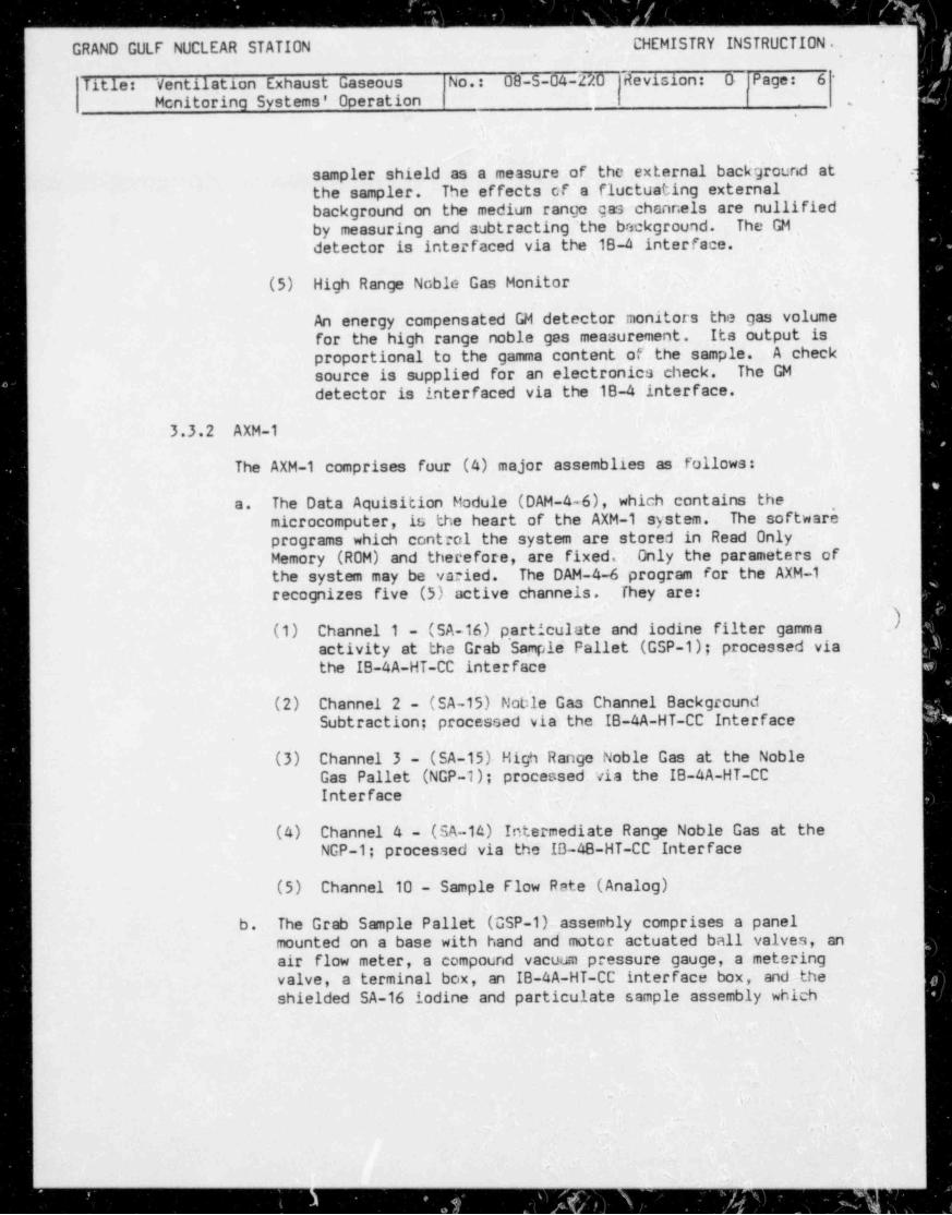
sampler shield as a measure of the external backg'round at .)the sampler. The effects of 's fluctuating externalbackground on the medium range gas channels are nullifiedby measuring and subtracting 'the beckground. The GM,s
detector is interfaced via the 1B-4 interface. -
(5) High Range Noble Gas Monitor . ,
An energy compensate'd GM detector monitors the gas volumefor the high range noble gas measurement. .Its output isproportional to the gamma content of the sample. A checksource is supplied for an electronics check. The GM
detector is interfaced via the 18-4 interface.
3.3.2 AXM-1
The AXM-1 comprises fuur (4) major assemblies as follows:
The Data Aquisition Module (DAM-4-6), which contains thea. ,
microcomputer, lu,the heart of the AXM-1 system. The softwareprograms which control the systen are stored in Read OnlyMemory (ROM) and therefore, are fixed. Only the parameters ofthe system may be varied. The DAM-4-6 program for the AXM-1recognizes five (5) active channels. They are:
(1) Channel 1 - (SA-16) p, articulate and iodine filter gamma.
activity at the Grab Sample ~ Pallet (GSP-1); processed viathe IB-4A-HT-CC interface
_ _
(2) Channel 2 - (SA-15) ~ Noble Gas Channel BackgroundSubtraction; processed via the IB-4A-HT-CC Interface
(3) Channel 3 - (SA-15) High Range Noble Gas at the NobleGas Pallet (NGP-1); processed. via the IB-4A-HT-CCInterface
(4) Channel 4 - (SA-14) Intermediate Range Noble Gas at theNGP-1; processed via the IB-48-HT-CC Interface
(5) Channel 10 - Sample Flow Rete (Analog)
b. The Grab Sample Pallet (GSP-1)-assembly comprises a panel '
mounted on a base with hand and motor actuated ball valves, anair flow meter, a compound vacuum pressure gauge, a metering '
valve, a terminal box, an IB-4A-HT-CC interface box,- and the-shielded SA-16 iodine and particulate sample assembly whichs
\
.
r
* i' '"
4, ,
-s/
' ,
_ --. _-- _ _ - - .- - - -
. .. .,
. GRAND GULF NUCLEAR STATION CHEMISTRY INSTRUCTION
Titla Ycntiittion Exhaust Ga:cous No.: 08-5-04-220 Rsvisicn O Pcg2 7. Monitoring Systems' Operat' ion'
-
{~% .~ can be removed and transported intact to the laboratory for h
analysis. The GSP-1 contains all necessary elements toperform the following functions:
(1) Collect particulate and iodine samples at a rate of 1/60of the normal sampler flow rate. -
(2) Obtain gaseous grab samples.
(3) Purge the assembly of radioactive gases.
(4) Remove safely the collected particulate and iodinesamples to a laboratory for analysis,
c. The Bulk Filter Assembly (BFA-1), located inline prior to themid-range and high range noble gas monitors, contains 2charcoal cartridges and 1 particulate filter which filters thesample stream, assuring a gaseous only sample enters the SA-14and SA-15 detectors' chambers.
d. The Ncble Gas Pallet (NGP-1) is comprised of two (2) noble gassampler assemblies (SA-14 and SA-15), a junction box, two (2)IB AA-HT-CC interface boxes, one (1) IB-48-HT-CC interfacebox, a CSM-2 check source mechanism, a 1 to 10 L/M flow meter,a compound vacuum-pressure gauge, and a differential pressureswitch which measures any pressure drop across the flow meterand provides a signal should the pressure drop, or the sampleflow stop.
~
3.3.3 Background Considerations for the SPING-4 and the AXM-1
a. Each detector in the system is optimized to respond to thetype of radiation it is intended to measure. However, a
| detector typically is not totally non-responsive to othertypes of radiation. Also, a detector cannot tell the
difference between radiation from the source it is intended tomeasure or from some interfering source. For instance, thebeta scintillation dstector viewing the particulate filterwill respond to all radioactivity whether it originates fromfission products, radon daughters, noble gas or ambient gammarays penetrating the lead shield. Therefore, a positive:
reading on a given detector may be an increase in theradiation of interest, or it may be an increase in someinterferlng radiation.
.
%
-
r>-
.
GRAND GULF NUCLEAR STATION CHEMISTRY INSTRUCTION .,
.
Titls: Vtntilstion Exhaust Gaseous No.: 08-5-04-220 Revision: 0 'Pggas 8Monitoring Syntems' Cperation >
,
!'
.
Tb. Beta Particulate Channel >
.):
(1) Redon Daughters
These are retained on the filter paper in the same manneras other particulates. The decay of the radon daughter.includes emission of both beta and alpha particles.Therefore, the count rate from the alpha particulatedetector is a good measurement of the intensity of theredon daughters. This assumes there are no alphaemitting isotopes other than radon in the sampled airstream.
'(2) Noble Gas
Any noble gas present in the free air space around thisdetector will contribute to its response. This responsewill be identical to the beta gas channel except inmagnitude since the free space is sr. aller than the betagas chamber volumei- Therefore, the beta gas channel -
could be used as a subtraction source to reduce theeffect of noble gas on the beta particulata detector.
,
'
Data taken with Kr-85 indicates ~ the particulatechannel's count rate (due to noble gas) is about 40% of
-}the beta gas channel's count rate.
- (3) Ambient Gamma,
A small portial of any gamma radiatimi present willpenetrate the, lead shielding and cause the detector torespond. The amount of this response ~ depends on thedirection and energy spectrum of the gamma radiation.Two possibilities exist for measurement and subsequentsubtraction of the. gamma background. One is the gammaarea monitor and the other is the imbedded G-M tube(gamma background detector). Studies of trends is thebest way to determine which ''f either.) would be the-
best subtraction source...
(4) Iodines
Under some conditions, icdine isotopes can be retained onthe particulate filter and contribute to the detector'sresponse. This effect is dependent on the chemical formof the iodine as well as the temperature, humidity andother arameters. Since it is highly variable, it cannotrbe measured and subtracted, but the user should be aware -it exists.
)
. . .
t- _ __m_ _ _ _ . _ _ _ _ - _ _ _ _ _ _ _ _ . _ _ _ . _ _ _ _ . _ _ _ . _ _ _ _ _ . - _ _ _ _ _ _ _ . _ _ _ _ _ _ - . _ - . _ _ _ _ - _ . . _ _ _ _ _ _ _ _ _ _ _ _ _ . _
. GRAND GULF NUCLEAR STATION CHEMISTRY INSTRUCTION
Tit 19: Ventilction Exhxuct Gareoua No.: 08-S-04-220 |Ravicion: O Prge: 9. Monitoring. Systems' Operation
()'
c. Iodine Channel -
(1) Noble Gas
Noble gas present in the free air space as well as any |" held-up" in the filter cartridge can contribute to the l
detector response. The normal set-up has the adjacentenergy window (i.e., 400-450 kev) subtracting from theI-131 window (i.e. , 339-389 kev). Therefore the isotopicmix of the noble gases and the resultant gamma yields andenergies determine what the ratio of responses in the twochannels would be.
(2) Ambient Gamma,
(a) Any gamma which penetrates the lead shield andreacts in the crystal will cause a response if itsdetected energy spectrum falls within one of theenergy windows. The ratio of the response of thetwo channels depends on both direction and energyspectrum of the gamma, but in practice remainsrelatively constant.
(b) Since the detector cannot differentiate betweeng gamma radiation (of the same energy) from noble gas
versus ambient, the selection of a subtractionfactor may be somewhat of a compromise.
d. Noble Gas Channels
The only intefering radiation in the noble gas channels wouldbe ambient gamma penetrating the lead shields. The same logicas in paragraph 3.3.3b.(3) above applies.
3.4 Detector Ranges (uC1/cc at approximately 60 L/M), Excluding the AXM-1Monitors
3.4.1 GE detectors
10 to 1.0E6 CPM
3.4.2 SPING-4 detectors (uCi/cc at approxmately 60 L/M)
(.
. . _ _
r- - - - ' - - - - - - - - - - - - - - - -- = = -- - -- --- - - --
GRAND GULF NUCLEAR STATION CHEMISTRY INSTRUCTION - ,
Iltlos Vcntilction Exhaust Grieoua No.: 08-5-04-220 .Rsvicion: 0 Paga 10'Monitoring Systems' Operation -
a. CH-1, beta particulate ---- 6.3E-12 to 2.4E-6 9
b. CH-2, alpha particulate -- used for background subtraction forCH-1
c. CH-3, Iodine-131 --- 1.4E-11 to 3.82E-6
d. CH 4, Energy above I-131 is the same detector as CH-3 and notan additional detector. Values from CH-4 are used forbackground subtraction for CH-3.
e. CH-5, Low Range Noble Gas
(1) Xe-133, 1.3E-7 to 4.8E-2
(2) Kr-85, 6.1E-8 to 2.3E-6
f. CH-7, Mid-range Noble Gas
(1) Xe-133, 9.2E-4 to 1.3E3
(2) Kr-85, 1.3E-2 to 1.9E4
g. CH-7, High Range Noble Gas)
(1) Xe-133, 1.0E-1 to 1.4E5
(2) Kr-85, 3.7E-1 to 5.2E5
3.4.3 AXM-1, NGP-1 Detectors [ gamma-bequerel MeV/cc ( 8q.MeV/cc)]
a. CH-3, High Range Noble Gas --- 4.14E2 to 4.14E7
b. CH-4, Intermediate Range Noble Ges --- 2.29E-1 to 2.29E4
3.4.4 AXM-1, GSP-1
The range is the same as for the CH-3, NCP-1 High Range Noble Gasmonitor.
3.5 Accident Condition
For purposes of an effluent release rate greater than the instantaneousrelease rate allowed by the GGNS Technical Specifications or an effluentrelease rate high enough to cause the normal range (low range)instrumentation to go off scale high.
.... - _
_ _ _ _ _ _ _ _ _ _ _ - _ _ _ _ _ _ _ _ - . .. .. . . .
GRAND GULF NUCLEAR STATION CHEMISTRY INSTRUCTION.
Titica Vtntilttion Exhruat Gz::aus No.: 08-S-04-220 |RLvision: 0 |Pegas 11Monitoring Systems' Operation !
-
:
(~s i
4.0 PREREQUISITES "
4.1 Check I&C calibration stickers to affirm that I&C calibration due dateshave not been exceeded.|
4.2 Inform Operations Shift Supervisor prior to operating the sample panel orvalves.
4.3 Apparatus Required
4.3.1 Filter holder assemblies
4.3.2 Charcoal filters|' 4.3.3 Particulate filters
4.3.4 Marinelli beakers
f 4.3.5 Tygon (or equivalent) tubing}| 4.4 Reagents Required
None
4.5 Attachments
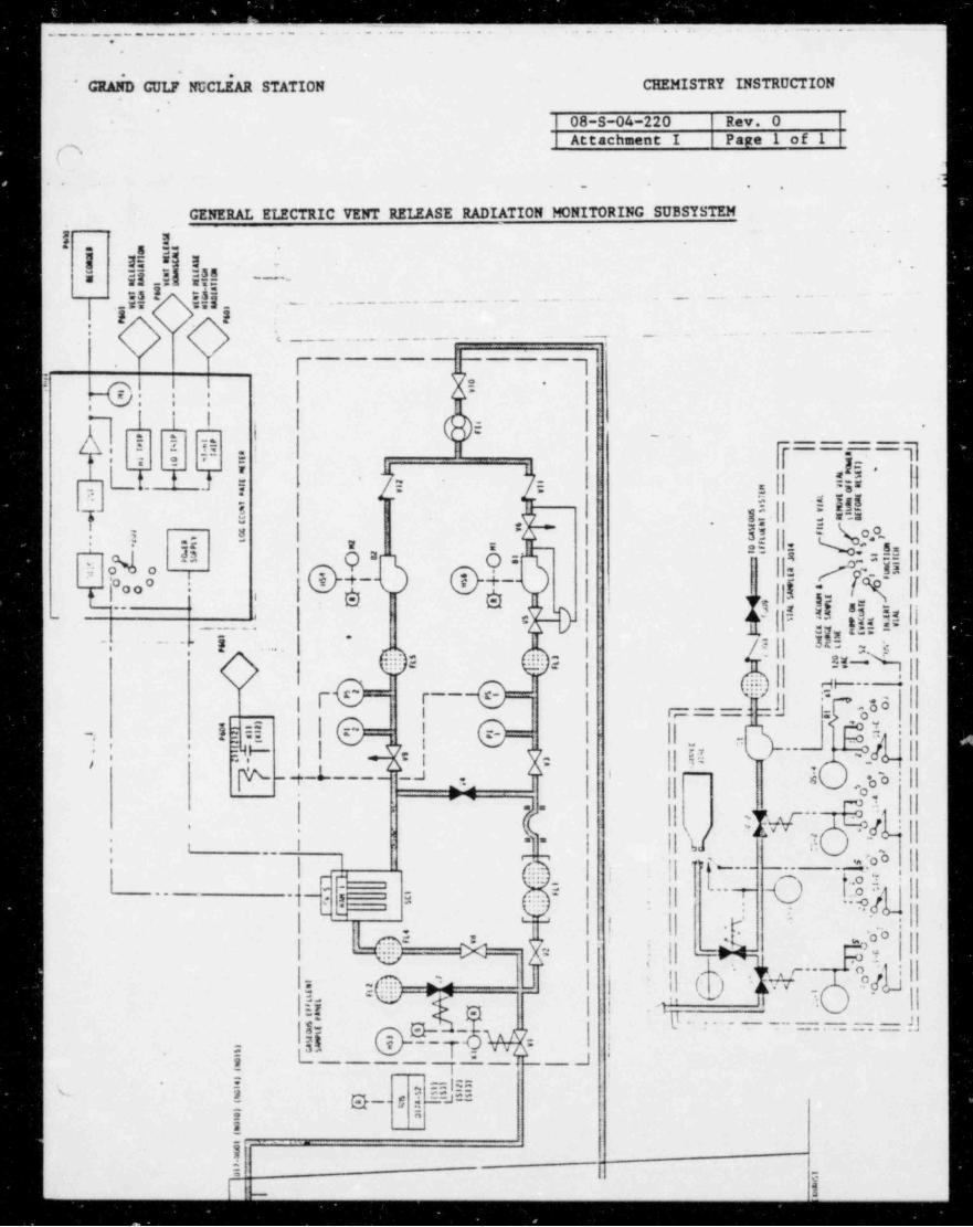
4.5.1 Attachment I - Grsneral Electric Vent Release Radiation MonitoringSubsystem
4.5.2 Attachment II - Accident Range and SPING Gaseous EffluentMonitoring Block Diagram
5.0 PRECAUTIONS
Be cognizant of high voltages associated with the monitoring systems and theradiological conditions that may be encountered while performing the functionscf this procedure.
6.0 INSTRUCTIONS I
NOTE
At any point in this instruction where a function is neither desired orrequired, the operator may proceed, or return to any step to achieve thedesired objective. This instruction includes the following sections:
Non-Panel Grab Sample Points, 6.1
s
_ _ _ _ _ _ . _ _ _ _ _ _ _ _ _ _ . _ _ _ _ .
.. _. _ _ _ _ - ___- __ ,, __ , _ _
_______ -
GRAND GULF NUCLEAR STATION CHEMISTRY INSTRUCTION ,
Titlos Ventilttion Exhaunt Gar:aun No.: 08-S-04-220 RLvicion: O Page: 12,
Monitoring Systems' Operation
'i
Gaseous Grab Samples, 6.1.1Particulate and Iodine Grab Samples, 6.1.2
General Electric Sample Panel, 6.2
Gaseous Grab Samples (None), 6.2.1Particulate and Iodine Grab Samples, 6.2.2
General Electric, 3034 and 3014 Vial Sampler, GaseoJs $8mpling, 6.3
SPING-4 Monitors Data Collection and Sampling, 6.4
Sample Count Data, 6.4.2Background Count Data, 6.4.3 and 6.4.4Grab Sampling, 6.4.5
AXM-1 Monitors Data Collection and Sampling, 6.5
Background Check, Non-Accident Condition, 6.5.1Sample Data Collection, 6.5.2Filter Change-Out, 6.5.3Grab Sampling, 6.5.4
Accident Conditions, 6.6 ])NOTE
This instruction assumes that an individual having the authority to grantpermission to operate the valves and switches on the ventilation monitoringsystems has granted permission for the chemist to proceed.
6.1 Non-Panel, Grab Sample Points
NOTE
This section applies to existing sampling points such as the samplingpoint located on the 136' elevation of the Radwaste Building, and tosimilar sample points which may be added in the future.
NOTE
Noble gas, particulate and iodine grab sampling can be donesimultaneously by attaching the Marinelli beaker, in series, to thefilter holder assembly, preferably to the outlet (iodine filter portion)end of the assembly. The following steps, however, do not follow thisapproach.
.
- - - . . _ . _ ,
GRAND CULF NUCLEAR STATION CHEMISTRY INSTRUCTION,
Titlo V;ntilr_ tion Exhau;t G wsoua No.: 08-S-04-220 Ravision: O Page 13Monitoring Systems' Operation.
.
6.1.1 Gaseous Grab Samples 9
a. As applicable, record the following:
(1) Ventilation Exhaust Flow Rate
(2) Activities from the ventilation exhaust noble gasmonitors (SPING-4 CH-5 low range, CH-7 mid-range, CH-9high range) as per Steps 6.4.1 and 6.4.2.a, b or c.
b. Attach the sampling tubing and apparatus as follows:
(1) Marinelli beaker inlet tubing to the sample outlet
(2) Marinelli beaker outlet tubing to the vacuum pump inlet
(3) The vacuum pump outlet to the sample point inlet
c. Open the Marinelli stopcocks and the sample inlet and outletvalves. '
d. Turn the vacuum pump ON.
e. Allow the vacuum flow to stabilize, then record the time.
f. Allow the sample to purge for five minutes.'
g. Note the time while simultaneously closing the sample outletand inlet valves, then close the Marinelli stopcocks.
h. Turn the vacuum pump Off.
1. Remove the sample and apparatus from the sampling ports.
J. Record the noted time (Step 6.1.1.g) and date,
k. If necessary, notify Operations shift supervision thatsampling has been completed.
6.1.2 Particulate and Iodine Grab Samples
a. As applicable, record the following:
b
I
-- _ _ _ - _ _ _ _ - _ - _ _ _ _ _ _ _ _ _ - - _
GRAND GULF NUCLEAR STATION CHEMISTRY INSTRUCTION,
Title Vantilttion Exhaust Garcous No.: 08-5-04-220 Ravision O Paga: 14 *
Monitoring Systems' Operation -.
(1) Ventilation Exhauct Flow Rate 9
(2) Activities from the particulate and iodine monitors(SPING-4 CH-1 Beta Particulate, CH-2-Alpha Particulate,CH-3 Iodine-131, CH-4-Energy above Iodine-131) as perSteps 6.4.1 and 6.4.2.a, b or c.
b. Install the filter holder assembly with the particulate filterend of the assembly serving as the inlet into the assembly.
c. Do Steps 6.1.1.c through 6.1.1.f, as applicable..
d. Note the time while closing the sample inlet and outletvalves.
e. Do Steps 6.1.1.h through 6.1.1.k, as applicable.
6.2 General Electric Sample Panel SD17
6.2.1 Gaseous Samples'
Since ventilation exhaust gaseous samples may also be obtained atthe GE panels, obtain gaseous samples acccrding to Sections 6.1,6.3, 6.4, 6.5 or 6.6, as. applicable. At GE panels,. sample fromeffluent side cf particulate sampler using same procedure listed in
-)6.2.2.a thru 6.2.2.d plus into from 6.1.1.
6.2.2 Particulate and Iodine Grab Samples
a. Record sample flow start date and time.
b. Record the value in line with the top edge of the top bevel onthe FI-1 float.
c. Close Valve V-3, then close Valve V-2.
d. Record the date and time that sample flow was stopped.
e. Observe and record the value indicated on FI-1.
f. Determine sample flow as follows:
Step 6.2.2.b value - Step 6.2.2.e = particulate / iodinesample flow
g. Remove the installed filter holder assembly from the quickdisconnects.*
)
..
..
;
. _ - --- - -. - .-
GRAND GULF NUCLEAR STATION CHEMISTRY INSTRUCTION,,
Titls: Vcntilction Exhaust Gareoua No.: 08-S-04-220 Rnvision: 0 :Pcgo: 15Monitoring Systems' Operation l
m''
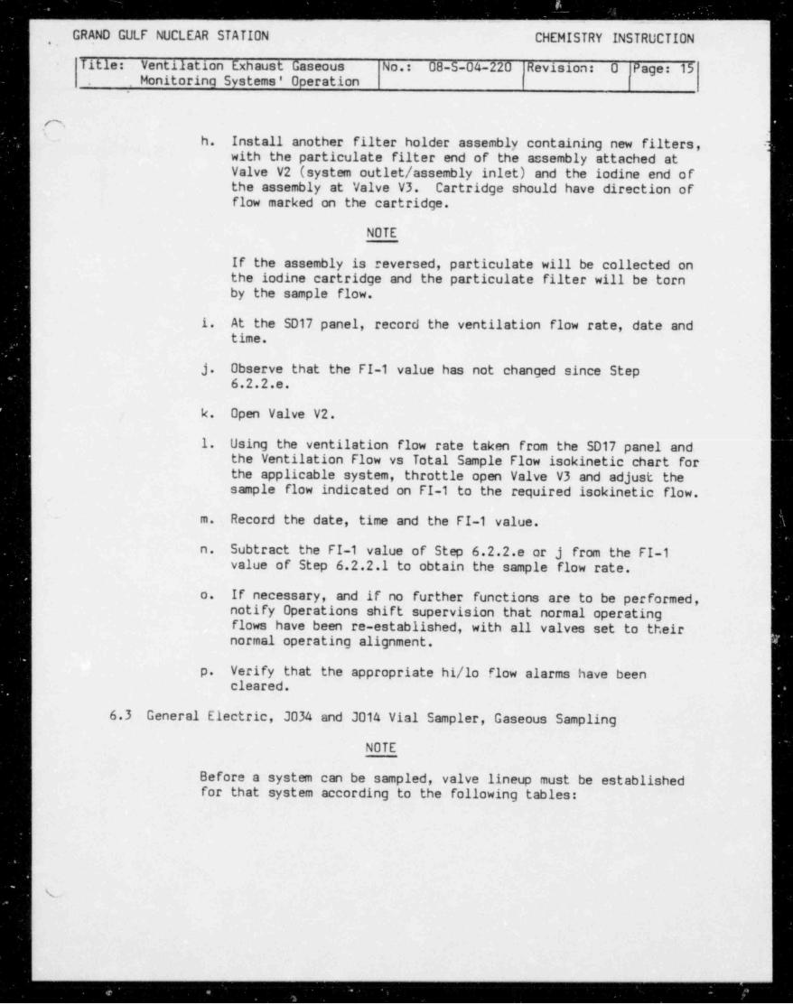
- h. Install another filter holder assembly containing new filters, -)with the particulate filter end of the assembly attached at
i Valve V2 (system outlet / assembly inlet) and the iodine end of) the assembly at Valve V3. Cartridge should have direction ofI flow marked on the cartridge.
NOTE
If the assembly is reversed, particulate will be collected on I
the iodine cartridge and the particulate filter will be tornby the sample flow.
1. At the SD17 panel, record the ventilation flow rate, date andtime.
J. Observe that the FI-1 value has not changed since Step6.2.2.e.
k. Open Valve V2.
1. Using the ventilation flow rate taken from the SD17 panel and |the Ventilation Flow vs Total Sample Flow isokinetic chart forthe applicable system, throttle open Valve V3 and adjust thesample flow indicated on FI-1 to the required isokinetic flow. I
m. Record the date, time and the FI-1 value.
Subtract the FI-1 value of Step 6.2.2.e or j from the FI-1n.value of Step 6.2.2.1 to obtain the sample flow rate.
If necessary, and if no further functions are to be performed,o.notify Operations shift supervision that normal operatingflows have been re-established, with all valves set to theirnormal operating alignment,
p. Verify that the appropriate hi/lo flow alarms ~ have beencleared.
6.3 General Electric, 3034 and 3014 Vial Sampler, Gaseous Sampling
NOTE
Before a system can be sampled, valve lineup must be establishedfor that system according to the following tables:
L
- _ _ _ _ - . - _ _ - _ - _ .
GRAND GULF NUCLEAR STATION CHEMISTRY INSTRUCTION -.
Titlos Ventilction Exhrunt G:ccous No.: 08-5-04-220 Rovision: O Pug'3: 16'
Monitoring Systems' Operation .
s
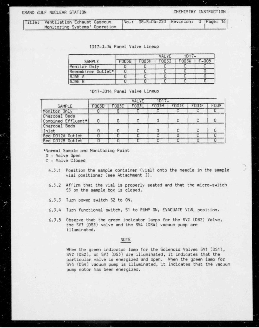
1D17-3-34 Panel Valve Lineup .)
VALVE 1D17-SAMPLE F003G F003H F003] F003K F-005
Monitor Only 0 C C C C .
Recombiner Outlet * O C C 0 0
SJAE A 0 C 0 C 0SJAE B 0 0 C C 0
1D17-3014 Panel Valve Lineup
VALVE 1D17-SAMPLE F003D F003C F003L F003M F003E F003F F009
Monitor Only 0 0 C C C C C
Charcoal BedsCombined Effluent * 0 0 C 0 C C 0
Charcoal BedsInlet 0 0 C 0 C C 0Bed D012A Outlet 0 0 C C 0 C 0Bed D012B Outlet 0 0 C C C 0 0
* Normal Sample and Monitoring Point0 - Valve OpenC - Valve Closed
36.3.1 Position the sample container (vial) onto the needle in the sample >
vial positioner (see Attachment I).
6.3.2 Affirm that the vial is properly seated and that the micro-switch53 on the sample box is closed.
6.3.3 Turn power switch S2 to ON.
6.3.4 Turn functional switch, S1 to PUMP DN, EVACUATE VIAL position.
6.3.5 Observe that the green indicator lamps for the SV2 (DS2) Valve,the SV3 (DS3) valve and the SV4 (DSA) vacuum pump areilluminated.
NOTE
When the green indicator lamp for the Solenoid Valves SV1 (DS1),SV2 (DS2), or SV3 (DS3) are illuminated, it indicates that theparticular valve is energized and open. When the green lamp forSV4 (DS4) vacuum pump is illuminated, it indicates that the vacuumpump motor has been energized.
.
. . . . .
.__ _-------- _ _ _ _ _ _ _ _ _ _ _ _ _ _ _ _ _ _ _ _ _ _ _ _ _ _ _ _ _ _ _ _ _ _ _ _ _ _ . . . _ _ _ _ _ _ _ , _
GRAND GULF NUCLEAR STATION CHEMISTRY INSTRUCTION, .
Titlos Vtntily. tion Exhrust Gm eous No.: 08-5-04-220 |Ravision O Pc:ga: 17Monitoring Systems' Operation l |
-
.
iNOTE
When step 6.3.1d. is executed, SV2 and SV3 were energized andthe K1 relay contacts were closed, providing power to energizethe vacuum pump, provided the sample vial wae properlyinstalled.
6.3.6 Check the vacuum gauge and allow the evacuation of the sample vialto the desired level (0 to 30" Hg).
6.3.7 Move the functional switch S1 to the CHECK VACUUM AND PURGE SAMPLELINE position.
|
6.3.8 Observe that the SV2 and SV4 green indicator lamps are illuminatedand that the SV3 lamp is extinguished.
.
NOTE
Step 6.3.1g. allows confirmation by checking the vacuum gauge,,
| that the seal between the sample vial and the sampler isadequate.
6.3.9 Check the vacuum gauge to affirm that the vacuum on the sample(. vial is maintained.
6.3.10 Move the function switch to PURGE position, and purge for therequired time.
6.3.11 Move the function switch S1 to FILL VIAL position.
NOTE
l
The vacuum pump is de-energized, SV2 closes, SV1 remains open, SV3opens to allow a gaseous sample to back fill into the samplevial.
6.3.12 Observe that the SV2 and SV4 lamps are extinguished and that theSV1 (DS1) and SV3 (OS3) lamps are illuminated.
6.3.13 After the vacuum pump gauge is stabilized, move the functionswitch S1 to REMOVE VIAL position.
NOTE
All the SV's are de-energized.
\. ..,
. - - _ _ - _ _ _ _ _ _ _ _ _ _ - _ _ _ - _ - - _ - - _ _ - - _ _ __ _ . _ _ - _
GRkND GULF NUCLEAR STATION CHEMISTRY INSTRUCTI0tl -
Tit 19: Vcntilition Exhrust G :cous No.: 08-5-04-220 R&vicion: 0 |Page 18
Monitoring Systems' Operation (
-
6.3.14 Observe that all green indicator lamps are extinguished.
6.3.15 Remove the sample container vial .from the sample vial positionerand place the container in a plastic bag and sample transporter.
CAUTION
To prevent loss of sample, Step 6.3.1.q should never precede Step6.3.1.o.
6.3.16 Position the power switch S2 to 0F.
6.3.17 Move functional switch S1 to its INSERT VIAL position.
6.3.18 Assure that valve lineup is restored to its original arrangement.
6.3.19 Notify Operations shift supervision that sampling has beencompleted.
6.4 SPING-4 Monitors (SA-9 and SA-13) Data Collection and Sampling
6.4.1 As applicable, remove or shield any radioactive sources which maycontribute activity to the detectors.
3NOTE
-
If filter change out is desired, proceed to Step 6.4.3, 6.4.4 or6.4.5, as applicable, or if flushing and background data collec-tion is required prior to obtaining sample count data, do Steps6.4.4 a then return to Step 6.4.2.
6.4.2 To obtain count data from the ventilation exhaunt, select one ofthe following steps (a, b, c or d):
a. From the SPING-4 Console, obtain the last printout of data,with date, time, vent flow and sample flow collected bythe monitoring system in the normal operating mode, or
b. Obtain the count values from the most recent data collected bythe monitoring system in the normal operating mode by rotatingc
the thumbwheel Channel Selector Switch to the desired channelsand recording the values, including date, time, ventilationflow rate and sample flow rate, using the thumbwheel switch toselect the desired channels as follows:
)
__- -. -
GRAND GULF NUCLEAR STATION CHEMISTRY INSTRUCTION.
Titlos Ventilation Exhru;t Gaa;oua No.: Od-S-04-220 |Rsvision: 0 |Peger 19-
Monitoring Systema' Oparrtion |
.
(,(1) Channel 1, Beta Particulate -)
(2) Channel 2, Alpha Particulate
(3) Channel 3, Iodine-131
(4) Channel 4, Energy above Iodine-131
(5) Channel 5, Noble Gas, low range (beta gas)1
(6) Channel 6, Area Gamma l
(7) Channel 7, Noble Gas, mid-range (gamma gas)
(8) Channel 8, Gamma Detector Background
(9) Channel 9, Noble Gas, high range (gamma gas),
| (10) Channel 10, Sample Flow Rate1
(11) Channel 11, Ventilation Effluent Flow Rate
If the data from Steps 6.4.1.a and/or b is unacceptable and/orc.
| unavailable, obtain permission from the I &.C Department andI select 6.4.2.c(1) or (2), and 6.4.2.c(3).
CAUTION..
The calibration switches should never be operated withoutpermission from the I & C Department.
(1) To obtain present count data at the console, set theSPING-4 Maintenance Mode Calibration Switch and allChannel Switches to ON and allow a minimum of twoprintouts (10 minutes each) on the console for eachchannel, then obtain the printout, including ventilationflow rate, sample flow rate, date and time.
NOTE
When the SPING-4 is in the Calibrate Mode for allchannels, count data for all channels is printed outevery 10 minutes on the console. To obtain data at thepanel, the chemist must wait ten minues for the countingto be completed, then rotate the thumbwheel ChannelSelector Switch to the desired channel number to obtaindata for each channel.
,
i. _
__ - _ _ - _ _ _ _ _ _ _ _ - - _ _ _ _ - - _ _ - - - _ - _
GRAND GULF NUCLEAR STATION CHEMISTRY INSTRUCTION ,
Titlos Vrntilttion Exhaust G::cous No.: 08-5-04-220 Rsvision: G Payye: 20 -
Monitoring Systema' Op ration.
3]> .(2) To obtain present count data at the panel, set theMaintenance Mode Calibration Switch and all ChannelSwitches to ON; then, after the first ten-minute countperiod, rotate the thumbwheel Channel Selector Switch tothe desired channel numbers as per Steps 6.4.2.b(1)through (11) and record the values, including date, time,ventilation flow rate and sample flow rate; then, whenthe second count period is completed, obtain and recordthose values.
(3) Set the Maintenance Calibrate Switch to 0FF for allchannels,
d. If necessary, notify Operations shift supervision whencompleted, and request that all alarms be cleared.
6.4.3 Background Check and Filter Change-out when radioactivity levelsfor all channels are at background
a. Background Checks are satisfied by Steps 6.4.2.a, b or c.
b. Filter Change-Out.
(1) Allow the monitoring system to remain in the sampling andanalysis mode.
(2) Rotate the SPING-4 thumbwheel Channel Selector Switch toChannel 10, then retst and record the Sample Flow Rate.
(3) Rotate the thumbwheel switch to Channel 11, then read andrecord the Ventilation Exhaust Flow Rate.
(4) Rotate the thumbwheel switch to the following channels toread the count values for the particulate and iodinechannels, if desired:
(a) Channel 1, Beta Particulate
(b) Channel 3, Iodine-131
(c) Channel 4, Energy above I-131
_ _ _ _ _ _ _ _ _ _ - _ _ _ _ - _ - _ - _ - - _ _ _ _ - _ _ - _ _ _ - - _ _ - _ - _ _ _ _ - - _ _ _ _ _ _ _ _ _ _ _ - - _ - _ _ _ - _ _ _ _ _ _ _ _ _ _ _ _ _ _ -
_ ___ - ___ - _______ __ - __. .-_ __
GRAND GULF NUCLEAR STATION CHEMISTRY INSTRUCTION,
Titlas Wntilttion Exhrust Ga=;ous No.: 08-S-04-220 RLvision 0 IPage 21-
,
Monitoring Syatema' Oparation.
t
$!
O' k(5) Note the time, while using the filter assembly retracting -1tool to carefully re'nove each assembly, holding each,
heavy assembly firmly to avoid dropping it.
(6) Transfer the used filters to adequately labeledcontainers.
(7) Place clean, new filters into each assembly, reinsert theassembly into the proper slot, and note the time.
(8) Record the dates and times noted in Steps 6.4.3.b(5) and(7). -
(9) If necessary, notify Operations shift supervision when'
completed, and request that all alarms be cleared.
6.4.4 Background Check and Filter Change-Out when radioactivity levelsin any channel is above background
a. Do Steps 6.4.3.b(2) and (3). '
b. If deemed necessary, press the FLUSH Switch, and record thetime sample flow was stopped.
i NOTE
When FLUSH is' initiated on the SPING-4, the sample (vacuum)'
pump for the SPING-4 system automatically shuts down, thepurge valve V2 opens and the sampling valve V5 closes, takingthe SPING-4 off-line and the AXM-2 (which is normally in thestandby mode, with its sample inlet valve closed and its purgeinlet valve open) is brought on-line as the AXM-1 purge inletvalve closes and the sample inlet valve opens.
When sufficient time has elapsed, rotate the thumbwheelc.
Channel Selector switch to all channels to determine ifactivity levels are decreasing.
i
d. When the activity levels no longer indicate a decrease, pulli out the particulate and lodine detector / filter holder
assemblies, remove the used filters and place the filters inadequatley labeled containers.
Place clean, new filters into each assembly, then reinsert thee.assembly into the proper slot.
v
b -
_ _. - -- . _ _ _ . _ _ - . _ . _ ._ _ _ . . .
*
GRAND GULF NUCLEAR STATION CHEMISTRY INSTRUCTION,
.
Tit 19: Vcntiittion Exhiuat G::eouc No.: 08-S-04-220 Revisinn O Prger 22Monitoring Systems' Operation 1
--
f. When sufficient time has elapsed, obtain background data, 9
if required, according to Step 6.4.2a, b or c.
g. Press the FLUSH Switch to terminate the flush.
h. Press the PUMP Switch to resume sampling and monitoring.
1. Record the time sampling and monitoring was resumed.
J. Do Steps 4.6.3.b(2) and (3).
k. If necessary, notify Operations shift supervision whencompleted, and request that all alarms be cleared.
6.4.5 Grab Sampling (SPING-4)
NOTE
Grab sampling is normally accomplished by utilizing the nor-panelgrab sample points, Section 6.1. Grab sampling, using the SPING-4panel may be used as desired, or as an alternative samplingmethod, when for any reason, normal sampling points cannot baused.
a. Gaseous Samples )
(1) If the SPING-4 is in the purge ' mode, press the pump ONswitch and allow the system to circulate forapproximately 5 minutes.
(2) Obtain and record the ventilation and sample flow rates.
(3) Attach the inlet and outlet tubes on the Marinelli beakerto the sample inlet and outlet valves at V3 and V4.
(4) Open the Marinelli beaker stopcocks.
(5) Open Valves V3 and V4 and close Valve V1.
(6) Record the time .ind date.1
(7) Allow the flow to ctabilize, note the sample flow rute,and if different from Step 6.4.5a.(2), record the value.
.
_.
- - GRAND GULF NUCLEAR STATION CHEMISTRY INSTRUCTION~
Tit 19: Ventliction Exhaust G neous No.: 08-S-04-220 Rsvision: O Pcgs: 23' Monitoring Systems' Operation
i mf
(8) At approximately 5 minutes after the flow rate J
stabilizes, note the time, close both Marinelli beakerstopcocks, and quickly open Valve V1.
(9) Close Valves V3 and V4.
(10) Record the time and date the stopcocks were closed in i-
Step 6.4.5.a(8). |
(11) Remove the sampling tubing from the sampling ports.
(12) If necessary, notify Operations shift supervision thatsampling has been completed and request that all alarms )be cleared.
b. Particulate and Iodine Sampling (SPING-4)
(1) Do Steps 6.4.3.b(2) and (3).,
(2) Attach the filter holder assembly as follows:
(a) Attach the assembly inlet (particulate filter end)to the left sample port (at V4) directly under theDISPLAY III A panel of the SPING-4 monitor. 1
!f(h) Attach the assembly outlet (iodine filter end) to
the sample port (at V3) on the right.
(3) Assure Valve V1 is closed. 1
(4) Assure vacuum pump is ON.
(5) Slowly open Valves V3 and V4 and record the time.
(6) Observe the sample flow rate, and if different from thevalue in Step 6.4.5.b(1), record the value.
(7) When the desired sampling ti:ae is reached, open Valve VI,then close Valves V3 and V4 simultaneously.
,
(8) Record the date and the exact time that Valves V3 and V4were closed.
(9) Remove the sampling apparatus.
U
- - - _ . _ _ - _ _ _ _ . _ _ _ _ _ _ _ _ _ _ _ _ _ _ _ _ - _ _ _ _ _ _ _ _ - _ _ _ __- --__ _
GR NO GULF NUCLEAR STATION CHEMISTRY INSTRUCTION
Title VIntiletion Exhrust Gaseous No.: 08-5-04-220 Ravision: O Pcgs: 24 ,
Monitoring Systems' Operation
i(10) If necessary, notify Operations chift supervision thatsampling has been completed and request that all alarmsbe cleared.
6.5 AXM-1 Monitors Data Collection and Sampling
NOTE
The AXM-1 system reniaAns in the purge mode except when:
1. the SPING-4 is inopertaive,
2. high radiation levels at the SPING-4 Mid-range noble gas monitorhave initiated the FLUSH command in the SPING-4, taking theSPING-4 subsystem 0FF-LINE, or when
3. The SPING-4 is in the FLUSH Mode for any reason.
NOTE
Steps 6.5.1.a and b assumes the AXM-1 is in the purge mode, and that theparticulate and iodine filters in the SA-16 (GSP-1) are free ofradioactive contaminants.
6.5.1 Background Check, Non-Accident Condition ,
a. Rotate the DAM-4 thumbwheel Channel Selector Switch to thedesired channel numbers, read and record the values, asnecessary, for the following channels:
(1) Channel 1, SA-16, Particulate and Iodine (GSP-1)
(2) Channel 2, SA-15, Noble gas Channel BackgroundSubtraction
(3) Channel 3, SA-15, High Range Noble Gas (NGP-1)
(4) Channel 4, SA-14, Mid-range Noble Gas (NGP-1)
(5) Channel 10, Sample (or purge) Flow Rate, as appicable
(6) Channel 11, Ventilation Exhaust Flow Rate, as applicable
b. Record the date and time, m applicable.
)
_ _ _
_ _ - _ _ --_ -_____ .
GRAND GULF NUCLEAR STATION CHEMISTRY INSTRUCTION,
'
| Titlas Vinti1& tion Exhaust Greeous No.: 08-5-04-220 Ravision: O Pega 25'
* Monitoring Systems' Operation.
! ('N'"
I 6.5.2 Sample Data Collection i
a. If, for any reason, the SPING-4 Subsystem is inoperative andthe AXM-1 is operating, proceed to Step 6.5.2.d.
b. Initiate the operation of the AXM-1 Subsystem by pressing theFLUSH Switch on the SPING-4.
c. If the PUNP on the AXM-1 did not activate, prese the AXM-1Pump switch, and assure that the pump is ON.
d. After allowing sufficient itme (ten minues or more) for count i
data collection, do Steps 6.5.1.a and b.
e. Record the date, time, the Sample Flow Rate from Channel 10and the Ventilation Exhaust Flow rate taken from Channel 11.
f. If necessary, notify Operations shift supevision whencompleted, and request that all alarms be cleared.
6.5.3 Filter Change-Out *
NOTE
Steps 6.5.3.a through h assumes that the AXM-1 is in the samplingt
and analysis mode. If the system is not on-line because of highradiation, filters can be changed out according to Step 6.5.3.f asdesired, without using valves V3, V4 and V5.
1
Rotate the DAM-4 thumbwheel Channel Selector Switch to CH-10,a.read and record tha $ ample Flow Rate, then rotate the switch toChannel 11, reac and record the Ventilation Exhaust Flow Rate.
b. Open valve V3, close valves V4 and V5, then record the dateand time the flow was stopped.
c. Reverse the Channel Selector Switch to Channel 2, read andrecord the count value, as necessary, then repeat this stepfor Channel 1.
d. If the radiation level in the SA-16 is low enough that the ,
assembly can be opened safely, preceed to Step6.5.3.f
If the radiation level in the SA-16 assembly is too high, ore.if contamination is possible should the assembly-be opened atthe panel, disconnect the detectors, release the clampsholding the SA-16 assembly, remove the assembly and replace itwith another prepared assembly, then proceed to Step 6.5.3.g.
a
.
GRAND GULF NUCLEAR STATION CHEMISTRY INSTRUCTION -
Titlo: Vtntilation Exh ust Gcccous No.: 08-S-04-220 Rsvision: U Pag 3: 26'' -
Monitoring Systems' Operation -
].f. Withdraw the detector / filter holder assembly from the SA-16,
place the used filters in adequately labeled containers,replace the used particulate and iodine filters with newfilters, then reinsert the assembly into the SA-16.
g. If no other functions are to be performed, open Valves V4 andVS, then close Valve V3 and note the time.
h. Record sample flow rate, ventilation flow rate, and the dateand time noted in Step 6.5.3.g.
1. If necessary, notify Operations shift supervision whencompleted, and request that all alarms be cleared.
6.5.4 Grab Sampling (AXM-1, GSP-1)
a. Gaseous Samples
NOTE
For gaseous grab sampling of this subsystem when the SPING-4 isinoperative or when high radiation levels have forced the SPING-4subsystem offline, refer to Section 6.6.1.
.,
(1) Using the DAM-4 DISPLAY III A channel select switch, Jobtain and record the activities from the SA-14 (CH-4mid-range NG) and SA-15 (CH-3 high range NG) monitors, ifnecessary.
(2) Record the date and time.
(3) Obtain and record the ventilation (CH-11) and sample flowrates (CH-10).
NOTE
If the panel sample flow indicator is to be used in Step6.5.4.a(9), do not open Valve V3 or close Valves V4 and V5 inthe following step. If the SA-16 assembly will not be valvedout, used filters in the assembly should be replaced withclean, new filters, as required.
).
=
- _ _ _ _ _ -- _ _ _ _ - - _ _ _ _ _ _ _ _ - _ _ _ _ _ _ .
GRAND GULF NUCLEAR STATION CHEMISTRY INSTRUCTION
Titlo Vcntflation Exhrust Gaseous No.: 08-S-04-220 :Ravicion: O Pcg3: 27. Monitoring Systems' Operation |
.
?(4) Open Valve V3, assure Valve V6 is open, close Valves V5 ~
and V4, then affirm that the SPING-4 is purging to assurethat GSP-1 is sampling.
(5) Attach the Marinelli beaker inlet and outlet tubes to thesampling parts at valves V7 and V8.
(6) Open the Marinelli beaker stopcocks, then open Valves V7and V8.
(7) Close Valve V6.
(8) Record the date and time.
(9) Allow the flow to stabilize and if the SA-16 was notvalved out, note the sample flow rate and if differentfrom Step 6.5.4.a(3), record the value.
(10) At one to five minutes after flow rate stabilization,note the time, close the Marinelli stopcocks, and quickly-open Valve V6.
NOTE
Activity levels determine sampling duration.
(11) Close Valves V7 and V8.
(12) If the SA-16 was valved out in Step 6.5.4.a(4), openValves V4 and VS, then close Valve V3.
(12) Record the time the Marinelli stopcocks were closed inStep 6.5.4.a(10), then remove the sampling tubing fromthe sampling ports.
(14) If necessary, notify Operations shift supervision thatsampling has been completed and request that all alarmsas cleared,
b. Particulate and Iodine Samples (AXM-1, OSP-1)
NOTE
Particulate and iodine grab sampling of this subsystem will berequired only when the SPING-4 is inoperative or when highradiation levels at the SPING-4 Mid-range noble gas monitorhave initiated the FLUSH command in the SPING-4, taking theSPING-4 off-line.
t
i
'
CNEMISTRV INSTRUCTION~
GRAN but CEEAESTATI0ti~- '~ ~
.
Titlos Vcntilation Exhault Grasous No.: 08-5-04-220 Ravision 0- Page: 28 .-
Monitoring Systems' Operation ,
(1) Obtain and record the ventilation and sample flow rates. r)(2) Open valve V3, then close Valves V4 and V5.
(3) Install the filter holder assembly with the particulateend of the apparatus toward Valve V8 and the lodine endtoward Valve V7.
(4) Open Valve V8, then V7.
(5) Close Valve V6.
(6) Record the date and time..
(7) Based on sample activity, allow sufficient time forcollecting a representative sample.
(8) Open Valve V6, close Valve V8, then close Valve V7.
(9) Record the time and date sample flow through the filterassembly was stopped.
(10) Disconnect the filter holder assembly lines from thesampling ports.
(11) Open Valves V4 and V5, then close Valve V3. )(12) As necessary, notify Operations shift supervision when
sampling is completd, and request that all alarms becleared.
3. Install the filter holder assembly with the particulatefilter end of the assembly serving as the inlet into theassembly.
b. Open the sample outlet and inlet valves.
6.6 Accident Conditions
NOTE
The normal condition of the Ventilation Exhaust Gaseous Systems in anaccident condition is to have the Standby Gas Treatment System operatingand all other release points isolated. Each release point has anaccident range monitor and is capable of accurately measuring accidentreleases, however; only the Standby Gas Treatment (SGT) monitors will be
')
_ __ J
~
GRAND GULF NUCLEAR STATION CHEMISTRY INSTRUCTION,
Titla #cntilEtion Exhiust Ga;cous No.: 08-5-04-220 Rsvicion O Pega 29,
Monitoring Syatema' Opsrction.
(5needed in an accident condition. If releases occur from other release ipoints during an accident, the following sections may be used to ensureproper monitoring and sampling.
6.6.1 Gaseous Sampling
Section 6.5.4 [AXM-1 (GSP-1) Subsystem] should be used forsampling with the 1 liter or 4 liter marinelli beaker. If theexpected concentrations are too high for counting in a marinelli,the following procedure may be used:
a. Substitute a piece of tygon tubing for the marinelli beakerand attach to the inlet and outlet tubes on the AXM-1.
b. Establish flow through the tygon tube per Step 6.5.4.a(1)through 6.5.4.a(9).
c. Evacuate a 14 ml off-gas vial.
d. Use a Hamilton gas syringe or equivalent to draw a gas samplefrom the tygon tube and note the time.
NOTE
Volume of gas may vary from approximately 1 m1 to 10 mldepending on tne expected concentration of the gas. ,
I
,
Transfer the gas to the evacuated off-gas vial.e.
f. Record the time noted in Step 6.6.1.d, and secure from gaseoussampling as per 6.5.4.a(10) through (14), as applicable.
6.6.2 Particulate / Iodine Monitors
Install silica gel or silver zeolite cartridges in the SGTa.monitors.
NOTE
The silica gel or silver zeolite cartridges are used tominimize the adsorption of noble gases on the cartridge thatmay interfere with the detection of I-131.
,
b. Install silica gel or silver zeolite cartridges in otherrelease point monitors as deemed necessary.
(_,
- - __.
'
GRAND GULF NUCLEAR STATION CHEMISTRY INSTRUCTION'
Titlos Vantilttian Exhaunt Garcous No.: 08-S-04-220 Rsvision: O Prge 30Monitoring Systems' Operation 1 -
-
s
6.6.3 Particulate / Iodine Sampling -1
Section 6.5.3 (AXM-1, GSP-1 Sample Panel) should be used forsampling during accident conditions.
NOTE
Silica gel or silver zeolite cartridges may be used to minimizeinterference from noble gas nuclides.
.
.s
.
e
&
_ _ . . __ .
.. j
-.._.......7! . .7C.-..-. . . - . . ----
..
. .
' GRAND GULF NUCLEAR STATION CHEMISTRY INSTRUCTION
.
08-S-04-220 Rev. OAttachment I Page 1 of I
cS0- . ..
GENERAL ELECTRIC VENT RELEASE RADIATION MONITORING SUBSYSTEM
i i- -
, m ..
i as s . '..
U 55 _EI E!! --
|__j| ? i|| _ . . - - - _ . . . . - - . . - . . . - . - - - - - - - - - - - - -
|~ _.
2 7 |2 . . - -. -- . - - - --
7__-......-...-.-. __ 4__
_
,4! i : Ii
I' '
I |A,111-= ..
i i n. ! -|-
-
9r 3... . , e r- .
c L_T. T f i 1 l s il sii ||'
- - .
3
|'
| i; 11 -i 155 ||%
y' t :=
53 3 \fS. ||1 ! | |'*
| "," ||i * =!a ll:Q d 4. g.6 --
'i-
ij= -?.
t_J-:
I @.4_.sN s I
4 P i _;._.
,3 |Il ,l. % ||
o
.i -
-
i.'_ 3L3 'us :, i
s| J| |
-
a, .
-
. , -sr.y,-||i
-- _ _ - . . . |
- -
j ,i .
-@... c'
s *a -
.I
$e--fj:d- lIr| F ,- [_ _
,_
| r;==={=0
i' d_ -- O . g)e :3~ L:llI I O-)'(= |@-- | Il1 : s!, .
II|||| 8 4.- i y; i ?
- -+| '-_
F g P j jj li'
j(C
j [[ W: . ib |I-J .
-
I.
|-
: , __ i- v I || s.d
. .
c _
|M' * *oO8
-1-f. . - *
t ii, ,.
1 'h'''==--'
-m-[ ll-**
'
h,a . | || -- 7 Oi-- -
_ :llI i i || .-- --
.
| ; || _si f-'
11I =C -:k =
_ . 3|m !. ^ .a,, u -r = v g li
-
.c-- o
|t @ :; _
| ii, ..
'
|gt _ _ _hgh~ u - - - - - == = = n
sl _- ,7=.__=_a-
,=.
i
E.E.c |EE== ==~' y a__ g ; a
2 Ti
1
i~
s -
[ 3. . - -
_--_-L;-_______________
1
- _ - _ _ ___ _ - - _ _ . - - . . _m _ . - - - - - -_ _ - - - - - , - - --------;-;- _- .
x4 < -- - . . ._ . __ . . _ . . . . . . . _ . . .
* '. .
. GRAND CULF NUCLEAR STATION CHEMISTRY INSTRUCTIONf
*.
08-S-04-220 Rev. 0Attachment II Page 1 of 1,g,
1 \ -.
ACCIDENT RANGE AND SPING GASEOUS EFFLUENT MONITORING BLOCK DIAGRAM 1<
E3
dh A ! 1
hp .'- e8, s*
,
'1..d, .. t, !! s v!,1 i ~. = .
w s s-~. -
D $, 3
M...,_______ 5, i, h!, , ,; , ,_
L d TS-s. =7 : e w ait;..
Lv I 4: =*;, g 4 a a* a=
$ Ex:ij B}Aa 9;5>.----<.-
N= -- 4, iWWYW,
4 u. .3 i,g, il%>---1 ,"
,.'
.. e i ..*SL 63
'
g-
&- a , %",'*!f3" {e!ku ----,e, a e i,2 -
w u s. Ie '!tu na'
~ - K
1 1m1 ~ td .
'
4it A' " "
ti;34s.4{*4
M s' -
<<41 2 .-I -
44 8 44S4s- 95@ld-]. e a a .y c m4. e 7 ,; ,;i . ,h 4kkklaIb,E4. . , . . . . . -
-
1% T -5li li . $Ui !aig bl.GGGGGGGGG
,
'I
- "^. au g
HY ?N _SlG dEe4D
IS !2 5 3 i i !!E
:,..:.. ?? j. ,
fj|.4,iS il! ? ' *
.bIOk'3~5s 3 - .
d j - :'
*...._....,iba
El-g h- g ~a 3{'|----IIIS
:
3& , q ingj.,
fiI! INN $i@7(FC
["
i i
!P5iMs. i,....j W.. ,e 4-
,
%. k ;., .. ,$ li. .!-.t's - 8
' t' O ;S'"' N k l*.m y %s aem '
D'f 4 h @H92-j i ;CN T''f, f% ,b h - y% 'O h Y. !iC'
| }g|i>e! P t.i N. . . M$g'
j! ! E,.! ri i!^
!
'n !e,. .g s2il 3 __A---------_--_----_ . - - _ - - - - _ Y!
-
t -..
:lihR _
-