Embed Size (px)
Citation preview
1
Excessive Loss: A Risk with Bend-Sensitive Fiber Cable 2
Macrobending and Bend-Insensitive Fiber 2
Macrobending Hurdles in New Use Cases 3
Fibers with Enhanced Macrobend Loss Performance: Bend-Insensitive Fibers 3
Restricted Wavelength Range and Link Distance: A Risk with Legacy SMF 4
SMF Specifications and Applications 4
Premises SMF Cable Specifications 7
Risks of Reusing Legacy SMF Cable 7
Multimode Fiber Upgrades: When Are They Needed? 8
MMF Specifications and Applications 8
Legacy OM1/OM2 Bandwidth and Limits 9
How to Choose Between OM3/OM4/OM5 9
Table of Contents
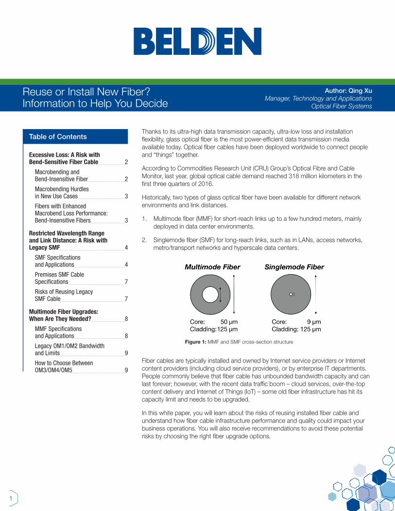
Reuse or Install New Fiber? Information to Help You Decide
Author: Qing Xu Manager, Technology and Applications
Optical Fiber Systems
Thanks to its ultra-high data transmission capacity, ultra-low loss and installation flexibility, glass optical fiber is the most power-efficient data transmission media available today. Optical fiber cables have been deployed worldwide to connect people and “things” together.
According to Commodities Research Unit (CRU) Group’s Optical Fibre and Cable Monitor, last year, global optical cable demand reached 318 million kilometers in the first three quarters of 2016.
Historically, two types of glass optical fiber have been available for different network environments and link distances.
1. Multimode fiber (MMF) for short-reach links up to a few hundred meters, mainly deployed in data center environments.
2. Singlemode fiber (SMF) for long-reach links, such as in LANs, access networks, metro/transport networks and hyperscale data centers.
Figure 1: MMF and SMF cross-section structure
Fiber cables are typically installed and owned by Internet service providers or Internet content providers (including cloud service providers), or by enterprise IT departments. People commonly believe that fiber cable has unbounded bandwidth capacity and can last forever; however, with the recent data traffic boom – cloud services, over-the-top content delivery and Internet of Things (IoT) – some old fiber infrastructure has hit its capacity limit and needs to be upgraded.
In this white paper, you will learn about the risks of reusing installed fiber cable and understand how fiber cable infrastructure performance and quality could impact your business operations. You will also receive recommendations to avoid these potential risks by choosing the right fiber upgrade options.
2
Macrobending and Bend-Insensitive Fiber
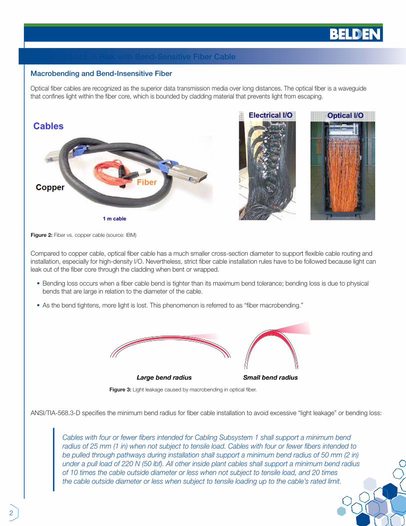
Optical fiber cables are recognized as the superior data transmission media over long distances. The optical fiber is a waveguide that confines light within the fiber core, which is bounded by cladding material that prevents light from escaping.
Excessive Loss: A Risk with Bend-Sensitive Fiber Cable
Figure 2: Fiber vs. copper cable (source: IBM)
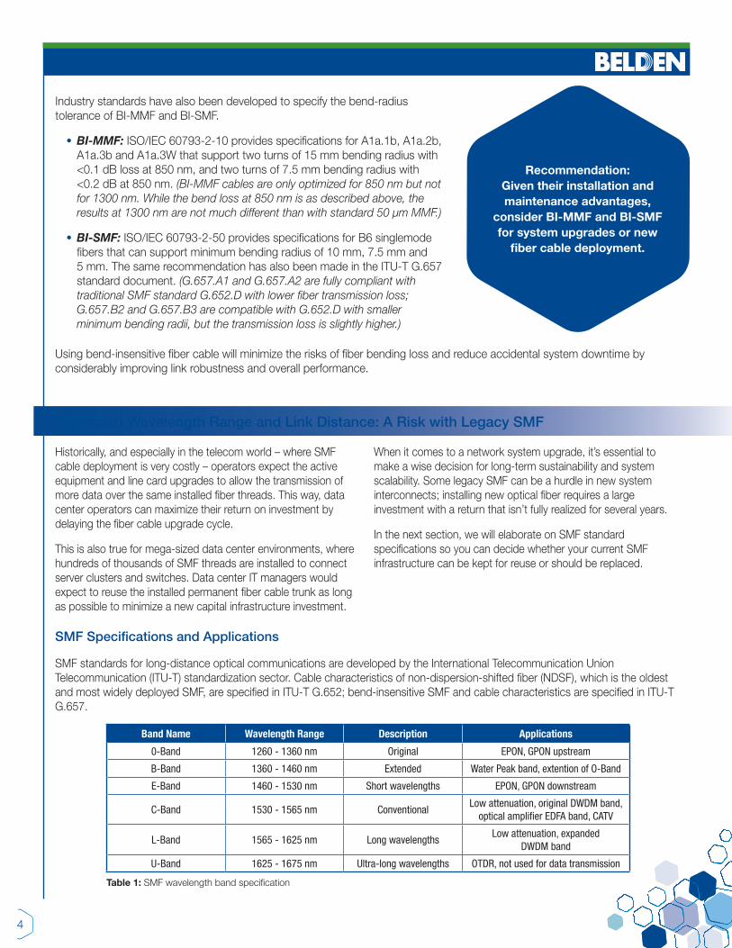
Figure 3: Light leakage caused by macrobending in optical fiber.
Compared to copper cable, optical fiber cable has a much smaller cross-section diameter to support flexible cable routing and installation, especially for high-density I/O. Nevertheless, strict fiber cable installation rules have to be followed because light can leak out of the fiber core through the cladding when bent or wrapped.
• Bending loss occurs when a fiber cable bend is tighter than its maximum bend tolerance; bending loss is due to physical bends that are large in relation to the diameter of the cable.
• As the bend tightens, more light is lost. This phenomenon is referred to as “fiber macrobending.”
ANSI/TIA-568.3-D specifies the minimum bend radius for fiber cable installation to avoid excessive “light leakage” or bending loss:
Cables with four or fewer fibers intended for Cabling Subsystem 1 shall support a minimum bend radius of 25 mm (1 in) when not subject to tensile load. Cables with four or fewer fibers intended to be pulled through pathways during installation shall support a minimum bend radius of 50 mm (2 in) under a pull load of 220 N (50 lbf). All other inside plant cables shall support a minimum bend radius of 10 times the cable outside diameter or less when not subject to tensile load, and 20 times the cable outside diameter or less when subject to tensile loading up to the cable’s rated limit.

3
Macrobending Hurdles in New Use Cases
In many new practical use cases, fiber cables are required to be installed with very tight bend radii, which could lead to unexpected high bending loss:
1. In access networks, optical fiber is installed closer to subscribers; therefore, smaller bend radius is required to support high-density, flexible fiber installation and routing.
2. In data center networks, more and denser fiber cables are installed to support ever-growing bandwidth requirements in limited space; therefore, hassle-free fiber cable installation with higher bend tolerance is increasingly important to reduce bending loss and speed up data center deployment and upgrades.
Legacy fiber cable, although optimized for low-attenuation data transmission, is subject to excessive transmission loss; it was not optimized to support sharp bends and can suffer from bending loss. Accidental fiber loss can happen on a daily basis if care is not taken:
• Sharp bend: Severe 90-degree bend can induce high link loss of 0.4 dB to 0.5 dB
• Pinched cable: Pinching standard fiber jumper can lead to an attenuation of 3 dB to 4 dB
• Fiber slack loop: A tight pulling tension on the fiber jumper can cause an attenuation of >5 dB
Figure 4: Causes of excessive fiber loss
Fibers with Enhanced Macrobend Loss Performance: Bend-Insensitive Fibers
Figure 5: Bend-insensitive fiber can be wrapped very tightly with very low loss
Recently, bend-insensitive SMF and MMF (BI-SMF and BI-MMF) products were introduced to the market to meet the needs of tighter fiber-bend tolerance to avoid bending loss. Optical fiber manufacturers use a refractive index “trench” in the fiber structure – a ring of lower refractive index material – to reflect lost light back into the core of the fiber.
4
Industry standards have also been developed to specify the bend-radius tolerance of BI-MMF and BI-SMF.
• BI-MMF: ISO/IEC 60793-2-10 provides specifications for A1a.1b, A1a.2b, A1a.3b and A1a.3W that support two turns of 15 mm bending radius with <0.1 dB loss at 850 nm, and two turns of 7.5 mm bending radius with <0.2 dB at 850 nm. (BI-MMF cables are only optimized for 850 nm but not for 1300 nm. While the bend loss at 850 nm is as described above, the results at 1300 nm are not much different than with standard 50 µm MMF.)
• BI-SMF: ISO/IEC 60793-2-50 provides specifications for B6 singlemode fibers that can support minimum bending radius of 10 mm, 7.5 mm and 5 mm. The same recommendation has also been made in the ITU-T G.657 standard document. (G.657.A1 and G.657.A2 are fully compliant with traditional SMF standard G.652.D with lower fiber transmission loss; G.657.B2 and G.657.B3 are compatible with G.652.D with smaller minimum bending radii, but the transmission loss is slightly higher.)
Recommendation: Given their installation and maintenance advantages,
consider BI-MMF and BI-SMF for system upgrades or new
fiber cable deployment.
Using bend-insensitive fiber cable will minimize the risks of fiber bending loss and reduce accidental system downtime by considerably improving link robustness and overall performance.
Historically, and especially in the telecom world – where SMF cable deployment is very costly – operators expect the active equipment and line card upgrades to allow the transmission of more data over the same installed fiber threads. This way, data center operators can maximize their return on investment by delaying the fiber cable upgrade cycle.
This is also true for mega-sized data center environments, where hundreds of thousands of SMF threads are installed to connect server clusters and switches. Data center IT managers would expect to reuse the installed permanent fiber cable trunk as long as possible to minimize a new capital infrastructure investment.
When it comes to a network system upgrade, it’s essential to make a wise decision for long-term sustainability and system scalability. Some legacy SMF can be a hurdle in new system interconnects; installing new optical fiber requires a large investment with a return that isn’t fully realized for several years.
In the next section, we will elaborate on SMF standard specifications so you can decide whether your current SMF infrastructure can be kept for reuse or should be replaced.
Restricted Wavelength Range and Link Distance: A Risk with Legacy SMF
SMF Specifications and Applications
SMF standards for long-distance optical communications are developed by the International Telecommunication Union Telecommunication (ITU-T) standardization sector. Cable characteristics of non-dispersion-shifted fiber (NDSF), which is the oldest and most widely deployed SMF, are specified in ITU-T G.652; bend-insensitive SMF and cable characteristics are specified in ITU-T G.657.
Band Name Wavelength Range Description Applications
0-Band 1260 - 1360 nm Original EPON, GPON upstream
B-Band 1360 - 1460 nm Extended Water Peak band, extention of O-Band
E-Band 1460 - 1530 nm Short wavelengths EPON, GPON downstream
C-Band 1530 - 1565 nm ConventionalLow attenuation, original DWDM band,
optical amplifier EDFA band, CATV
L-Band 1565 - 1625 nm Long wavelengthsLow attenuation, expanded
DWDM band
U-Band 1625 - 1675 nm Ultra-long wavelengths OTDR, not used for data transmission
Table 1: SMF wavelength band specification

5
SMF was originally optimized for use in the 1310 nm wavelength region (O-band) in premises cabling, but it can also be used in the 1550 nm (C-band) wavelength region. The zero-dispersion wavelength range is set between 1300 nm and 1324 nm to minimize transmission penalty due to chromatic dispersion.
This type of fiber cable was installed mostly in the 1980s, but there was a high absorption wavelength range due to hydroxyl (-OH) molecules within the fiber, which makes the E-band (water peak band) unusable. The E-band represents the region in which a standard fiber is most affected by attenuation caused by the hydroxyl molecules in the glass core structure.
In metro and access networks, one fiber carries signals on multiple wavelengths and over multiple wavelength bands to increase overall bandwidth and maximize fiber use. Recently, optical fiber manufacturers drastically reduced E-band losses and made it an extension of the O-band.
Figure 6: Legacy SMF vs. low-water-peak SMF
Note: When using E-band as an O-band extension, the transmission reach limit is set by the wavelength with the highest attenuation (i.e. lowest wavelength used in O-band). Some vendors claim that a zero-water-peak (or no-water-peak) fiber can essentially extend link reach, but such an unpractical system would exclude the use of O-band where the fiber attenuation is higher.
The offers of “very low-water-peak fiber” also have no practical benefits, considering that the low-water-peak attenuation at 1383 nm is already defined lower than that at 1310 nm. The industry has therefore agreed not to pursue “no-water-peak” perfection for cost and environmental considerations (i.e. depletion of energy and drying chlorine gas).
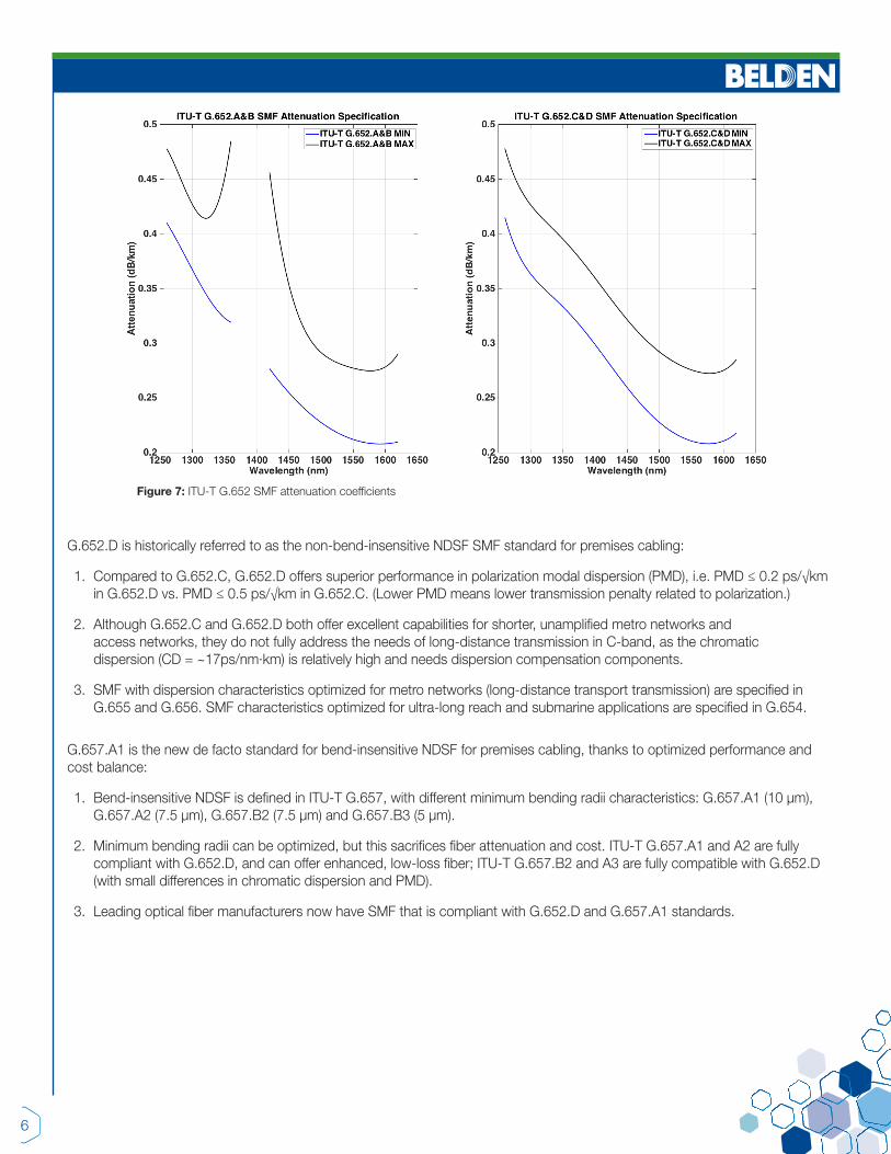
In Figure 7 (shown on page 6), we show the ITU-T-specified SMF characteristics in G.652.A and G.652.B (conventional) and G.652.C and G.652.D (low-water-peak).
The newer G.652.C and G.652.D standards have been developed to specifically reduce the water peak at the 1383 nm wavelength range, and to add an additional operating E-band window for applications such as next-generation access networks and mobile fronthaul (connection between a network of centralized baseband controllers and remote standalone radio heads at cell sites). These fiber types offer extremely low attenuation around the -OH peaks and can support operation from O-band to L-band (1260 nm to 1625 nm).
6
Figure 7: ITU-T G.652 SMF attenuation coefficients
G.652.D is historically referred to as the non-bend-insensitive NDSF SMF standard for premises cabling:
1. Compared to G.652.C, G.652.D offers superior performance in polarization modal dispersion (PMD), i.e. PMD ≤ 0.2 ps/√km in G.652.D vs. PMD ≤ 0.5 ps/√km in G.652.C. (Lower PMD means lower transmission penalty related to polarization.)
2. Although G.652.C and G.652.D both offer excellent capabilities for shorter, unamplified metro networks and access networks, they do not fully address the needs of long-distance transmission in C-band, as the chromatic dispersion (CD = ~17ps/nm∙km) is relatively high and needs dispersion compensation components.
3. SMF with dispersion characteristics optimized for metro networks (long-distance transport transmission) are specified in G.655 and G.656. SMF characteristics optimized for ultra-long reach and submarine applications are specified in G.654.
G.657.A1 is the new de facto standard for bend-insensitive NDSF for premises cabling, thanks to optimized performance and cost balance:
1. Bend-insensitive NDSF is defined in ITU-T G.657, with different minimum bending radii characteristics: G.657.A1 (10 µm), G.657.A2 (7.5 µm), G.657.B2 (7.5 µm) and G.657.B3 (5 µm).
2. Minimum bending radii can be optimized, but this sacrifices fiber attenuation and cost. ITU-T G.657.A1 and A2 are fully compliant with G.652.D, and can offer enhanced, low-loss fiber; ITU-T G.657.B2 and A3 are fully compatible with G.652.D (with small differences in chromatic dispersion and PMD).
3. Leading optical fiber manufacturers now have SMF that is compliant with G.652.D and G.657.A1 standards.
7
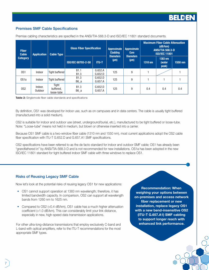
By definition, OS1 was developed for indoor use, such as on campuses and in data centers. The cable is usually tight buffered (manufactured into a solid medium).
OS2 is suitable for indoor and outdoor use (street, underground/burial, etc.), manufactured to be tight buffered or loose-tube. Note: “Loose-tube” means not held in medium, but blown or otherwise inserted into a carrier.
Because OS1 SMF cable is a two-window fiber cable (1310 nm and 1550 nm), most current applications adopt the OS2 cable fiber specification with ITU-T G.652.D and G.657.A1 SMF specifications.
OS2 specifications have been referred to as the de facto standard for indoor and outdoor SMF cable; OS1 has already been “grandfathered in” by ANSI/TIA-568.3-D and is not recommended for new installations. OS1a has been adopted in the new ISO/IEC 11801 standard for tight buffered indoor SMF cable with three windows to replace OS1.
Risks of Reusing Legacy SMF Cable
Now let’s look at the potential risks of reusing legacy OS1 for new applications:
• OS1 cannot support operation at 1383 nm wavelength; therefore, it has limited bandwidth capacity. In comparison, OS2 can support all wavelength bands from 1260 nm to 1625 nm.
• Compared to OS2 (<0.4 dB/km), OS1 cable has a much higher attenuation coefficient (<1.0 dB/km). This can considerably limit your link distance, especially in new, high-speed data transmission applications.
Recommendation: When weighing your options between
on-premises and access network fiber replacement or new
installation, replace legacy OS1 with a new bend-insensitive OS2
(ITU-T G.657.A1) SMF cabling to support longer reach with enhanced link performance. For other ultra-long-distance transmissions that employ exclusively C-band and
L-band with optical amplifiers, refer to the ITU-T recommendations for the most appropriate SMF types.
Premises SMF Cable Specifications
Premise cabling characteristics are specified in the ANSI/TIA-568.3-D and ISO/IEC 11801 standard documents.
Fiber Cable
CategoryApplication Cable Type
Glass Fiber Specification Approximate Cladding
Diameters (µm)
Approximate Core
Diameters (µm)
Maximum Fiber Cable Attenuation (dB/km)
ANSI/TIA 568.3-DISO/IEC 11801
ISO/IEC 60793-2-50 ITU-T 1310 nm1383 nm (water peak)
1550 nm
OS1 Indoor Tight bufferedB1.1B1.3
G.652.AG.652.D
125 9 1 1
OS1a Indoor Tight bufferedB1.3B6_a
G.652.DG.657.A
125 9 1 1 1
OS2Indoor,
Outdoor
Tight buffered,
loose-tube
B1.3B6_a
G.652.DG.657.A
125 9 0.4 0.4 0.4
Table 2: Singlemode fiber cable standards and specifications

8
Fiber Cable
Category
Glass Fiber Specification Approximate Cladding
Diameters (µm)
Approximate Core
Diameters (µm)
Minimum Modal Bandwidth (MHz-km) Maximum Fiber Cable Attenuation (dB/km)
ANSI/TIA 568.3-DISO/IEC 11801
Overfilled Launch (OFL) Modal Bandwidth
Effective Modal Bandwidth (EMB)
ISO/IEC 60793-2-10
ANSI/TIA-492
850 nm 953 nm 1300 nm 850 nm 953 nm 850 nm 953 nm 1300 nm
OM1 A1b TIA-492AAAA 125 62.5 200 500 3.5 1.5
OM2 A1a.1 TIA-492AAAB 125 50 500 500 3.5 1.5
OM3 A1a.2 TIA-492AAAC 125 50 1500 500 2000 3.0 1.5
OM4 A1a.3 TIA-492AAAD 125 50 3500 500 4700 3.0 1.5OM5
(WBMMF)A1a.3W TIA-492AAAE 125 50 3500 1850 500 4700 2740 3.0 2.3 1.5
Table 3: Multimode fiber cable standards and specifications
Figure 8: Multimode fiber characteristics
MMF is mainly deployed in data centers and local area networks for short-reach interconnects up to a few hundred meters.
In this section, we will elaborate on the main MMF standard specifications that have been developed to support new high-speed applications, and help you decide if your fiber cable system should be upgraded.
Multimode Fiber Upgrades: When Are They Needed?
MMF Specifications and Applications
The original multimode fiber (MMF) standard, ANSI/TIA-492AAAA (OM1, 62.5/125 µm), was released in 1989 to support Fast Ethernet 100BASE-FX and 1000BASE-SX, with a high numerical aperture (NA) of 0.275 and light capture from 1300 nm LED sources.
The ANSI/TIA-492AAAB standard for OM2 (50/125 µm) was released in 1998, with an improved modal bandwidth and a reduced NA of 0.2 to support higher data transmission, such as 1 Gbps VCSEL with longer reach.
To meet growing bandwidth requirements, laser-optimized multimode fiber (LOMMF) standards OM3 and OM4 were developed in 2002 and 2009, respectively, with effective modal
bandwidths (EMBs) of 2000 MHz/km and 4700 MHz/km to support 10G, 40G and 100G Ethernet applications, as well as InfiniBand and Fibre Channel protocols.
Historically, multimode optics operate with a single wavelength; MMF standards (OM1/OM2/OM3/OM4) have only specified the minimum bandwidth at 850 nm and 1300 nm (1300 nm LED is no longer used for system speeds of 10G or above). OM4+ is a non-standard product that offers a higher EMB than standard OM4 at the 850 nm wavelength. Recently, OM5 (wideband MMF) was developed and standardized in TIA and ISO/IEC organizations to support shortwave wavelength division multiplexing (SWDM) from 840 nm to 953 nm.
9
How to Choose Between OM3/OM4/OM5
Currently, OM3 and OM4 (including OM4+) are the most popular MMF types deployed in modern data centers; OM5 was just recently introduced to the market, so we’ll wait to see how long it takes for OM5 to be added to this list.
• OM3 MMF can support the latest Ethernet and Fibre Channel applications with reduced reach; however, cautions must be taken when mating legacy OM3 MMF with new bend-insensitive MMF (BI-MMF). The slight difference in fiber geometry could cause additional loss, negatively impacting cable performance.
• OM4 BI-MMF is recommended for new fiber installation or fiber upgrades and replacement projects because the latest application standards are developed based on OM4 specifications. OM4+ supports the same applications as OM4 and can extend the maximum reach.
• OM5 is backward compatible with OM4, so it supports the equal reaches for the current applications using single λ, such as 40GBASE-SR4 AND 100GBASE-SR4. Its main differentiation is to support the transmission of multiple wavelengths over the single MMF thread. Paired with OM5, BiDi and SWDM-based transceivers can considerably lower fiber cable and connectivity cost for point-to-point connections, using duplex fiber cable instead of MPO-12 trunk cable.
Legacy OM1/OM2 Bandwidth and Limits
Although OM1 and OM2 MMF have been widely deployed in the past, they are no longer suitable for new Ethernet infrastructure deployment – mainly due to the intrinsic limited EMBs. Let’s take an up-close look at potential risks you may face when reusing legacy OM1 and OM2 fiber cable instead of completing a fiber upgrade.
• OM1 (core diameter 62.5 µm) has different fiber geometry and can cause excessive signal loss even at short reach when mating with newer MMF types (core diameter 50 µm).
• OM1 and OM2 can only support very limited reach for links above 1G and can no longer support the system speed upgrade. In the new ANSI/TIA-568.3-D standard, OM1 and OM2 MMF types are “grandfathered in” and are not recommended for new greenfield installation.
• OM1 and OM2 have higher fiber cable attenuation (3.5 dB/km) compared to OM3/OM4/OM5 (3.0 dB/km); therefore, the link budget may not be met.
10
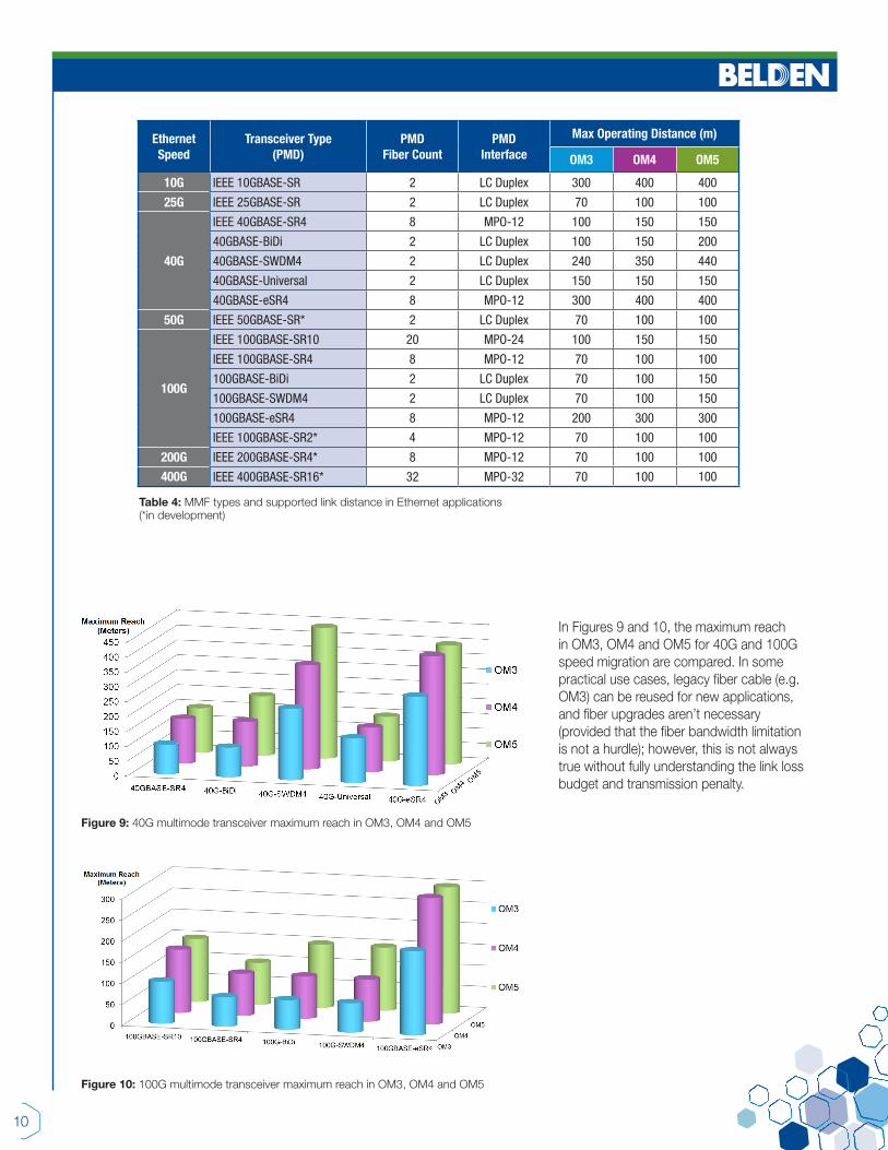
Figure 10: 100G multimode transceiver maximum reach in OM3, OM4 and OM5
Figure 9: 40G multimode transceiver maximum reach in OM3, OM4 and OM5
In Figures 9 and 10, the maximum reach in OM3, OM4 and OM5 for 40G and 100G speed migration are compared. In some practical use cases, legacy fiber cable (e.g. OM3) can be reused for new applications, and fiber upgrades aren’t necessary (provided that the fiber bandwidth limitation is not a hurdle); however, this is not always true without fully understanding the link loss budget and transmission penalty.
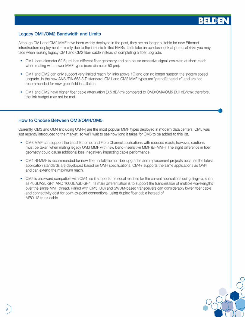
Ethernet Speed
Transceiver Type (PMD)
PMD Fiber Count
PMD Interface
Max Operating Distance (m)
OM3 OM4 OM5
10G IEEE 10GBASE-SR 2 LC Duplex 300 400 400
25G IEEE 25GBASE-SR 2 LC Duplex 70 100 100
40G
IEEE 40GBASE-SR4 8 MPO-12 100 150 150
40GBASE-BiDi 2 LC Duplex 100 150 200
40GBASE-SWDM4 2 LC Duplex 240 350 440
40GBASE-Universal 2 LC Duplex 150 150 150
40GBASE-eSR4 8 MPO-12 300 400 400
50G IEEE 50GBASE-SR* 2 LC Duplex 70 100 100
100G
IEEE 100GBASE-SR10 20 MPO-24 100 150 150
IEEE 100GBASE-SR4 8 MPO-12 70 100 100
100GBASE-BiDi 2 LC Duplex 70 100 150
100GBASE-SWDM4 2 LC Duplex 70 100 150
100GBASE-eSR4 8 MPO-12 200 300 300
IEEE 100GBASE-SR2* 4 MPO-12 70 100 100
200G IEEE 200GBASE-SR4* 8 MPO-12 70 100 100
400G IEEE 400GBASE-SR16* 32 MPO-32 70 100 100
Table 4: MMF types and supported link distance in Ethernet applications (*in development)
© Copyright 2017, Belden Inc. Reuse or Install New Fiber? Information to Help You Decide | WP00040 | V1 | ECOS_BDC_0717_A_AG
Belden Technical Support 1.800.BELDEN.1 www.belden.com11
In addition, as we show in Table 5, connectivity performance (insertion loss per connection) of the new OM4 and OM5 cabling system is far more superior compared to legacy OM3, which, in turn, will provide more link margin for longer distance and allow more points of connection.
Fiber TypeFiber Cable Loss
(@850 nm)
MPO-12 Insertion Loss
(per connection)
LCInsertion Loss
(per connection)LegacyOM3
3.5 dB/km 0.5 dB 0.25 dB
OM4OM5
3.0 dB/km 0.20 dB 0.15 dB
Table 5: Example of MMF cable loss and connectivity loss (legacy OM3 vs. new OM4 and OM5)
This prevents light from escaping and causing bend-induced attenuation, and leads to higher bandwidth capabilities and improved link and connectivity performance.
With this wise investment, your IT department can reduce total cost of ownership in the long run, with fewer maintenance hassles, easier troubleshooting and faster replacement. Fiber upgrades for old or legacy systems also ensure solid link performance and support next-generation upgrade cycles.
Recommendation: When it comes to network speed upgrades toward 40G, 100G
and beyond with MMF, replace old OM1/OM2 or legacy OM3
with high-quality OM4 BI-MMF cabling, or take a close look at OM5 if you plan to use BiDi or
SWDM-based transceivers.
Here are a few quick tips for your fiber upgrade:
Follow the industry standard and application guidance
Plan the migration path in advance
Keep your fiber infrastructure backward and forward compatible
Choose the most appropriate architecture and transmission media
Futureproof the cable infrastructure with a high-quality connectivity solution