Embed Size (px)
Citation preview
Retrotec Inc 1060 East Pole Rd. Everson, WA USA 098247 Ph. 360-738-9835
Retrotec Inc.
DM-2 Operation Manual rev-2012-12-27
Page 2 of 74
©Retrotec Inc. 2012
1 DM-2 Digital Gauge Basics ............................................................................... 8
1.1 Gauge Overview............................................................................................................... 8 1.1.1 The Connections Panel .................................................................................................................................. 8
Figure 1: DM-2 back panel with pressure ports and electrical connections .............................................8
1.1.2 The DM-2 Screen ........................................................................................................................................... 9
Table 1: DM-2 Gauge Screen .....................................................................................................................9
1.1.3 The Keypad .................................................................................................................................................. 10
1.2 Batteries ........................................................................................................................ 10 1.2.1 Install batteries ........................................................................................................................................... 10
To install batteries for the first time ....................................................................................................... 10
1.2.2 Charging batteries ....................................................................................................................................... 11 1.2.3 Operating on Rechargeable batteries ......................................................................................................... 11 1.2.4 Rechargeable or non-rechargeable (alkaline) batteries .............................................................................. 11 1.2.5 Replacing batteries ...................................................................................................................................... 11
To select proper battery type .................................................................................................................. 12
1.2.6 View the remaining battery power ............................................................................................................. 12
Figure 3: Splash screen and the main screen with battery life indication in the top left. ..................... 12
1.3 Resetting the Gauge ....................................................................................................... 12 To reset a DM-2 with the Reset button ................................................................................................... 12
To reset a DM-2 without using the Reset button .................................................................................... 12
1.4 Screen Contrast .............................................................................................................. 13 To change the screen contrast ................................................................................................................ 13
2 DM-2 Keypad Functions .................................................................................. 14
2.1.1 On/Off (Backlight) ...................................................................................................................................... 14 2.1.2 Exit ............................................................................................................................................................... 14
Copyright © 2012 Retrotec Inc.
All rights reserved.
This document contains materials protected under International and Federal Copyright Laws. This book contains material protected under International and Federal Copyright Laws and Treaties. Any unauthorized reprint or use of this material is prohibited. No part of this book may be reproduced or transmitted in any form or by any means, electronic or mechanical, including photocopying, recording, or by any information storage and retrieval system without acknowledging Retrotec Inc. as the original source.
Retrotec makes no warranties with respect to this documentation and disclaims any implied warranties of merchantability, quality, or fitness for any particular purpose. The information in this document is subject to change without notice. Retrotec reserves the right to make revisions to this publication without obligation to notify any person or entity of any such changes.
Infiltrometer, FanTestic, and DucTester are Trademarks of Retrotec Inc. Other Trademarks or brand names mentioned herein are trademarks or registered trademarks of their respective owners.
Page 3 of 74
©Retrotec Inc. 2012
2.1.3 Enter (Volume/Area) ................................................................................................................................... 14 2.1.4 Device .......................................................................................................................................................... 14 2.1.5 Mode ........................................................................................................................................................... 15
Table 2: Possible results and selectable units for the gauge .................................................................. 15
2.1.6 Range Config ............................................................................................................................................... 15 2.1.7 Setup ........................................................................................................................................................... 16 2.1.8 Baseline ....................................................................................................................................................... 16
To establish a baseline pressure .............................................................................................................. 16
2.1.9 Time Avg ...................................................................................................................................................... 17 2.1.10 Auto Zero ................................................................................................................................................ 17 2.1.11 Set Pressure ............................................................................................................................................ 17
To use the Set Pressure function ............................................................................................................. 17
2.1.12 Set Speed ................................................................................................................................................ 18
To use the Set Speed function ................................................................................................................. 18
2.1.13 Jog/Hold .................................................................................................................................................. 18
To activate Hold: ...................................................................................................................................... 18
In Set Speed ............................................................................................................................................. 19
In Set Pressure ......................................................................................................................................... 19
2.1.14 @ Pressure .............................................................................................................................................. 19
In Set Speed mode ................................................................................................................................... 19
In Set Pressure mode ............................................................................................................................... 20
Example #1 - Inaccuracy .......................................................................................................................... 20
Example #2 – Cannot reach desired pressure in Set Speed mode .......................................................... 20
Example #3 – Display results at any pressure. ........................................................................................ 20
3 Set the Gauge up with only the Devices and results you use regularly ............ 21
3.1 Setup Menu ................................................................................................................... 21 Table 3: Settings available on the gauge [Setup] ................................................................................... 21
3.1.1 Full Screen Timeout ..................................................................................................................................... 22
To change the Full Screen Timeout time period ..................................................................................... 22
3.1.2 Restore Settings .......................................................................................................................................... 22
To restore the factory settings ................................................................................................................ 22
3.1.3 Language ..................................................................................................................................................... 23
To change the language........................................................................................................................... 23
3.1.4 Battery Type ................................................................................................................................................ 23
To select a battery type ........................................................................................................................... 23
3.1.5 Display Version Info .................................................................................................................................... 23
To view version information .................................................................................................................... 23
Page 4 of 74
©Retrotec Inc. 2012
3.1.6 n setting for estimating flow @ pressure during house and duct leakage test .......................................... 24
To change the n value.............................................................................................................................. 25
3.1.7 Power Down Hour ....................................................................................................................................... 25
To change the Power Down Hour ........................................................................................................... 25
3.1.8 Surface Area Unit ........................................................................................................................................ 26
To change the Area units ......................................................................................................................... 26
3.1.9 Building Volume Unit .................................................................................................................................. 26
To change the Volume units .................................................................................................................... 26
3.1.10 European, Separator ............................................................................................................................... 26
To change the European Separator units ................................................................................................ 27
3.1.11 Sig Figs..................................................................................................................................................... 27
Table 4: Example values displayed using each of the three significant figure options. ......................... 27
To change the number of Significant Figures .......................................................................................... 27
3.2 Device Setup .................................................................................................................. 27 Table 5: List of compatible devices that can be used with the DM-2 .................................................... 27
3.2.1 Enable and Disable Devices ......................................................................................................................... 29
To enable/disable Devices ....................................................................................................................... 29
3.2.2 Enable and Disable Range Configurations ................................................................................................... 29
Table 6: DM-2 compatible devices and associated Flow Range configurations ..................................... 30
To enable/disable Flow Range configurations in Device [Setup] ............................................................ 30
3.3 Mode Setup ................................................................................................................... 30 Table 7: Default result Mode set-up ....................................................................................................... 30
To configure Modes: ................................................................................................................................ 31
4 Understand the Pressure Gauge...................................................................... 32
4.1 Differential Pressure ...................................................................................................... 32 To measure a pressure ............................................................................................................................ 32
Figure 4: Gauge displaying 249.5 Pa (or 1 in WC). .................................................................................. 32
4.2 Positive vs. Negative Pressure ........................................................................................ 32 Measure a negative pressure .................................................................................................................. 33
Figure 5: The gauge displaying a negative pressure (-251.5 Pa). ........................................................... 33
4.3 Analog Magnehelic Gauges ............................................................................................ 33 Figure 6: Digital and analog gauges display a pressure of 50.2 Pa. (RetrotecDigital DM-2 left);
Retrotec’s magnehelic gauge system (right). .......................................................................................... 34
5 Reduce Bias pressures, static or fluctuating .................................................... 35
Reduce fluctuating pressures created by wind ........................................................................... 35
6 Reduce uncertainty in results by taking lots of readings .................................. 37
Page 5 of 74
©Retrotec Inc. 2012
Table 8: Test result uncertainties vary by changing the number of baseline points, the baseline time,
and Time Averaging for induced pressures. ............................................................................................ 37
7 Check your gauge to see if it needs to be sent to factory for re-calibration ..... 38
7.1 Verify your gauge calibration between factory calibrations ............................................ 38 To perform a tubing check ...................................................................................................................... 38
Figure 7: Yellow tube between Channel A & B. Blue tube check of positive ports. Green from
negative to positive ports. ....................................................................................................................... 38
Figure 8: Gauge field check configuration: Cross port check, input ports (left) and reference ports
(right) ....................................................................................................................................................... 39
To perform a cross port check ................................................................................................................. 39
Figure 9: Gauge field check configuration: Cross gauge check .............................................................. 40
To perform a T-connection Fan Pressure check ...................................................................................... 40
Figure 10: Fan Pressure check using a T-connection .............................................................................. 40
To perform a syringe check (not as good as the cross-channel check) ................................................... 40
Figure 11: Syringe check setup ............................................................................................................... 41
8 Use the Gauge with a calibrated fan for air leakage testing............................. 42
8.1 Making the Connections ................................................................................................. 42 8.1.1 Pressure port connections .......................................................................................................................... 42
Figure 12: Pressure ports and control connections on the gauge. ......................................................... 43
8.1.2 Control connections .................................................................................................................................... 43
To connect the gauge to a Retrotec fan or variable speed fan drive ...................................................... 43
To connect the gauge to a Minneapolis Model 3 or Model 4 Fan .......................................................... 44
8.2 Control a fan with the gauge to measure pressure and flow ........................................... 44 To conduct a basic pressure test and ensure your gauge is working ...................................................... 44
8.3 Measure Air Handler flow using Hole Flow on the gauge ................................................ 45 To create an Exhaust Fan Flow Meter ..................................................................................................... 45
Figure 13: Exhaust fan flow meter .......................................................................................................... 45
9 Troubleshooting ............................................................................................. 47
Table 9: Causes of common problems ................................................................................................... 47
9.1 Check if moving tubes are causing fluctuating pressure .................................................. 47 To see the effect of a moving tube .......................................................................................................... 48
Figure 14: The effect of a moving tube on pressure readings. ............................................................... 48
9.2 Check if wind is causing fluctuating pressure .................................................................. 48 9.2.1 Use the [@ Pressure] key to reduce the effects of wind ............................................................................ 48 9.2.2 Use Time Averaging feature to reduce the effects of wind ........................................................................ 49
[Time Avg] exercise to practice reducing the effects of wind ................................................................. 49
9.2.3 Use Baseline feature to reduce the effects of a constant wind .................................................................. 49
Page 6 of 74
©Retrotec Inc. 2012
[Baseline] exercise to practice minimizing the effects of wind ............................................................... 49
9.2.4 In extreme cases you can use a Wind Damping Kit designed to reduce wind-related fluctuations ........... 49
Figure 15: Wind damping kits; basic (left) and deluxe (right). .............................................................. 50
No cost wind damping procedure ........................................................................................................... 50
9.3 Let Time Averaging take effect before making readings .................................................. 50 To learn how Time Averaging can cause error ........................................................................................ 50
9.4 Check if large fixed errors are caused by pinched tubes .................................................. 51 Figure 16: Errors in pressure reading from a pinched tube. .................................................................. 51
9.5 Check if large fixed errors are caused by water in the tube ............................................. 51 Figure 17: Water in the reference tube (left); high fixed pressure due to water (right). ...................... 52
9.6 Check if large fixed errors are caused by sun heating the tubes ....................................... 52
9.7 Results will be wrong if the Range and Device being used are different than those selected on the gauge ............................................................................................................................. 52
To determine correct flow if Range selected was different than the actual Range used: ...................... 52
9.8 Fans without reference tube have results adjusted by gauge .......................................... 53
9.9 Pressure can overshoot when using the Set Pressure key ............................................... 53
9.10 Keep the Keep Rechargeable Batteries in top shape ....................................................... 54 To charge the batteries: .......................................................................................................................... 54
9.11 If the Serial Number and Calibration Date are not valid .................................................. 55
9.12 If the keys on the DM-2 Keypad are not working ............................................................ 55 To fix the keypad if the keypad cable has come loose and keys are not working .................................. 55
9.13 Updating Firmware ........................................................................................................ 56 9.13.1 Firmware Changes .................................................................................................................................. 56
Table 10: Firmware changes from versions prior to 2.29 to the current version 3.01b. ........................ 56
Appendix A: The gauge calculates Flow based on Pressure readings from the fan ...... 58
To determine the flow for a particular fan pressure FP: ......................................................................... 59
Check that the measured value for FP meets the two conditions based on MF and K2. If so, find the N,
K, K1, and K3 values in Table xxx (based on the type of fan and the Range Configuration being used),
enter those values along with the values measured for FP, and RP into the Flow equation stated above
and calculate the result. .......................................................................................................................... 59
Table 11: N and K coefficients for all gauge supported fans. ................................................................. 59
Table 12: N and K coefficients for all gauge supported fans which are now Obsolete. ......................... 61
Appendix B: Manually calculate Flow if required test pressure cannot be reached .... 62
Cannot Reach 50 Pa Factors ....................................................................................................... 62 Table 13: Factors for when a building pressure of 50 Pa cannot be reached (“n” value of 0.65) .......... 62
Cannot Reach 25 Pa Factors ....................................................................................................... 63 Table 14: Factors for when a building pressure of 25 Pa cannot be reached (n value of 0.6) ............... 64
Appendix C: Errors occur in estimated flow if gauge and actual “n” don’t match ....... 65
Table 15: Errors in Estimated Flow at 50 Pa if gauge "n"= 0.65 differs from actual n ........................... 65
Page 7 of 74
©Retrotec Inc. 2012
Table 16: Errors in Estimated Flow at 50 Pa if gauge "n" = 0.60 differs from actual n .......................... 65
Appendix D: Adjust Flow values for temperature difference ...................................... 67
Table 17: Temperature correction factors for enclosure DEPRESSURIZATION ...................................... 67
Table 18: Temperature correction factors for enclosure PRESSURIZATION .......................................... 68
Appendix E: Tables to correct Flow if range selected did not match installed range ... 69
Appendix F: Setting up for a test with Alaska’s AkWarm software .............................. 71
Glossary ...................................................................................................................... 72

Page 8 of 74
©Retrotec Inc. 2012
1 DM-2 Digital Gauge Basics
The DM-2 is Retrotec’s two channel digital micromanometer, or differential pressure gauge. It combines simple but comprehensive functionality, with intuitive controls and setup. The DM-2 is a dual channel digital gauge that always displays a pressure on Channel A, but will display either measured pressure on Channel B, or calculate flow, air changes per hour, leakage area and display that on Channel B depending on the Mode selected. To ensure accurate results, the DM-2 takes up to four pressure readings per second on each channel, and updates the information displayed on the screen every second.
1.1 Gauge Overview
The Retrotec DM-2 mark II gauge has: a connections panel, a display screen, and a keypad. The connections panel on the back of the gauge is where all external devices are connected to the DM-2. The display provides information on the current test mode and/or setup, as well as the device status and measurement values. The keypad is where the user inputs data to the DM-2, and controls the DM-2 functions.
1.1.1 The Connections Panel
Figure 1: DM-2 back panel with pressure ports and electrical connections
Electronic function:
1. Control fan speed. (NOT for Internet connection)
2. Mini USB connection to a PC 3. Reset button 4. Battery charger input
Pressure Ports:
5. Input B (+) 6. Reference B (-) 7. Reference A (-) 8. Input A (+)
Page 9 of 74
©Retrotec Inc. 2012
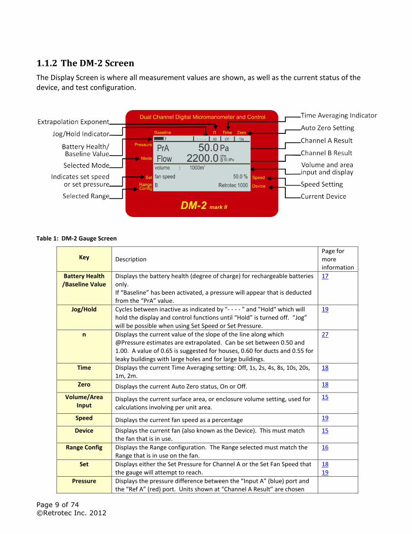
1.1.2 The DM-2 Screen
The Display Screen is where all measurement values are shown, as well as the current status of the device, and test configuration.
Table 1: DM-2 Gauge Screen
Key Description Page for more information
Battery Health /Baseline Value
Displays the battery health (degree of charge) for rechargeable batteries only. If “Baseline” has been activated, a pressure will appear that is deducted from the “PrA” value.
17
Jog/Hold Cycles between inactive as indicated by "- - - - " and "Hold" which will hold the display and control functions until “Hold” is turned off. “Jog” will be possible when using Set Speed or Set Pressure.
19
n Displays the current value of the slope of the line along which @Pressure estimates are extrapolated. Can be set between 0.50 and 1.00. A value of 0.65 is suggested for houses, 0.60 for ducts and 0.55 for leaky buildings with large holes and for large buildings.
27
Time Displays the current Time Averaging setting: Off, 1s, 2s, 4s, 8s, 10s, 20s, 1m, 2m.
18
Zero Displays the current Auto Zero status, On or Off. 18
Volume/Area Input
Displays the current surface area, or enclosure volume setting, used for calculations involving per unit area.
15
Speed Displays the current fan speed as a percentage 19
Device Displays the current fan (also known as the Device). This must match the fan that is in use.
15
Range Config Displays the Range configuration. The Range selected must match the Range that is in use on the fan.
16
Set Displays either the Set Pressure for Channel A or the Set Fan Speed that the gauge will attempt to reach.
18 19
Pressure Displays the pressure difference between the “Input A” (blue) port and the “Ref A” (red) port. Units shown at “Channel A Result” are chosen
Page 10 of 74
©Retrotec Inc. 2012
using [Setup]
Mode Displays the current results being calculated by the gauge (being shown on “Channel B Result”). “Channel B Result” depends on the pressure difference between the “Input B” (green) port and the “Ref B” (yellow) port (usually connected to the fan) and other parameters entered into the gauge.
16
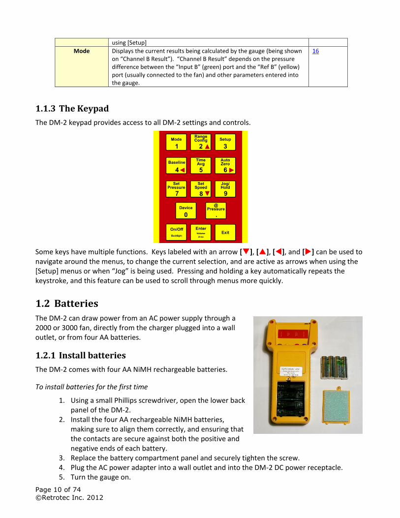
1.1.3 The Keypad
The DM-2 keypad provides access to all DM-2 settings and controls.
Some keys have multiple functions. Keys labeled with an arrow [], [], [], and [] can be used to navigate around the menus, to change the current selection, and are active as arrows when using the [Setup] menus or when “Jog” is being used. Pressing and holding a key automatically repeats the keystroke, and this feature can be used to scroll through menus more quickly.
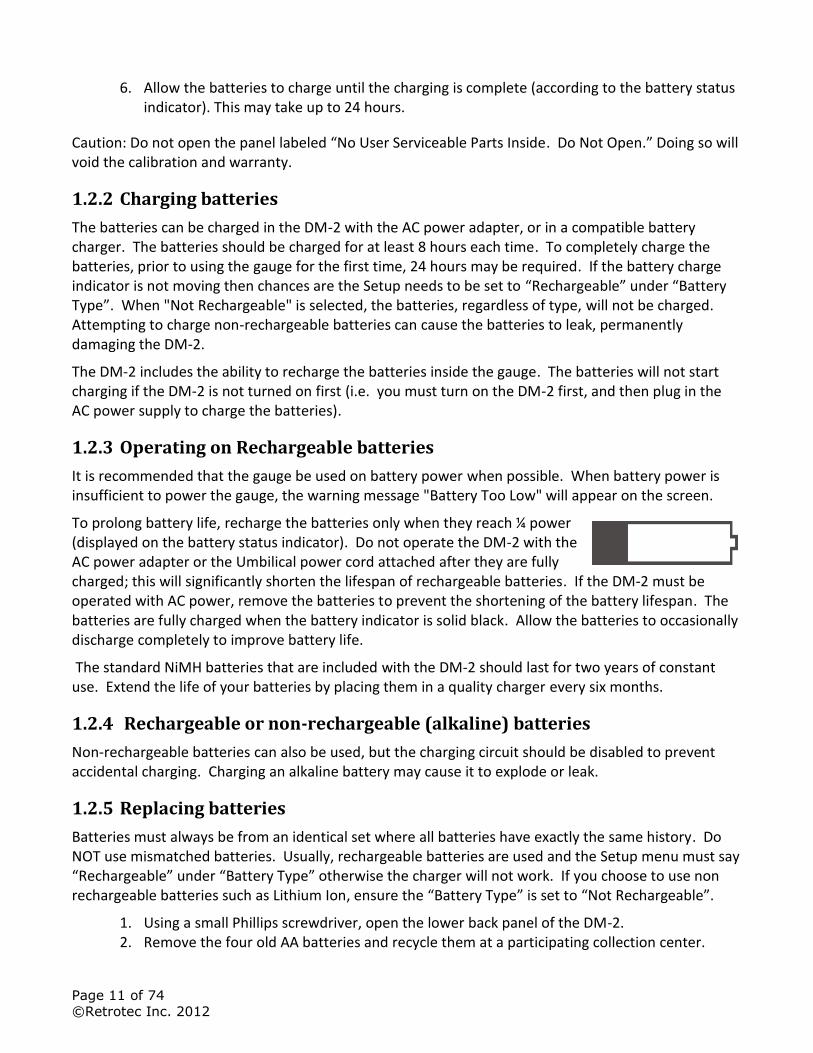
1.2 Batteries
The DM-2 can draw power from an AC power supply through a 2000 or 3000 fan, directly from the charger plugged into a wall outlet, or from four AA batteries.
1.2.1 Install batteries
The DM-2 comes with four AA NiMH rechargeable batteries.
To install batteries for the first time
1. Using a small Phillips screwdriver, open the lower back panel of the DM-2.
2. Install the four AA rechargeable NiMH batteries, making sure to align them correctly, and ensuring that the contacts are secure against both the positive and negative ends of each battery.
3. Replace the battery compartment panel and securely tighten the screw. 4. Plug the AC power adapter into a wall outlet and into the DM-2 DC power receptacle. 5. Turn the gauge on.
Page 11 of 74
©Retrotec Inc. 2012
6. Allow the batteries to charge until the charging is complete (according to the battery status indicator). This may take up to 24 hours.
Caution: Do not open the panel labeled “No User Serviceable Parts Inside. Do Not Open.” Doing so will void the calibration and warranty.
1.2.2 Charging batteries
The batteries can be charged in the DM-2 with the AC power adapter, or in a compatible battery charger. The batteries should be charged for at least 8 hours each time. To completely charge the batteries, prior to using the gauge for the first time, 24 hours may be required. If the battery charge indicator is not moving then chances are the Setup needs to be set to “Rechargeable” under “Battery Type”. When "Not Rechargeable" is selected, the batteries, regardless of type, will not be charged. Attempting to charge non-rechargeable batteries can cause the batteries to leak, permanently damaging the DM-2.
The DM-2 includes the ability to recharge the batteries inside the gauge. The batteries will not start charging if the DM-2 is not turned on first (i.e. you must turn on the DM-2 first, and then plug in the AC power supply to charge the batteries).
1.2.3 Operating on Rechargeable batteries
It is recommended that the gauge be used on battery power when possible. When battery power is insufficient to power the gauge, the warning message "Battery Too Low" will appear on the screen.
To prolong battery life, recharge the batteries only when they reach ¼ power (displayed on the battery status indicator). Do not operate the DM-2 with the AC power adapter or the Umbilical power cord attached after they are fully charged; this will significantly shorten the lifespan of rechargeable batteries. If the DM-2 must be operated with AC power, remove the batteries to prevent the shortening of the battery lifespan. The batteries are fully charged when the battery indicator is solid black. Allow the batteries to occasionally discharge completely to improve battery life.
The standard NiMH batteries that are included with the DM-2 should last for two years of constant use. Extend the life of your batteries by placing them in a quality charger every six months.
1.2.4 Rechargeable or non-rechargeable (alkaline) batteries
Non-rechargeable batteries can also be used, but the charging circuit should be disabled to prevent accidental charging. Charging an alkaline battery may cause it to explode or leak.
1.2.5 Replacing batteries
Batteries must always be from an identical set where all batteries have exactly the same history. Do NOT use mismatched batteries. Usually, rechargeable batteries are used and the Setup menu must say “Rechargeable” under “Battery Type” otherwise the charger will not work. If you choose to use non rechargeable batteries such as Lithium Ion, ensure the “Battery Type” is set to “Not Rechargeable”.
1. Using a small Phillips screwdriver, open the lower back panel of the DM-2. 2. Remove the four old AA batteries and recycle them at a participating collection center.
Page 12 of 74
©Retrotec Inc. 2012
3. Install four new AA batteries, making sure to align them correctly, and ensuring that the contacts are secure against both the positive and negative ends of each battery.
4. Replace the battery compartment panel and securely tighten the screw.
If a different type of battery is used (i.e. change from rechargeable to non-rechargeable), make sure to change the battery type in the Setup Menu of the DM-2.
To select proper battery type
1. Press [Setup]. 2. Scroll to "Battery Type" and select "Rechargeable" or "Not Rechargeable" as needed. 3. Press [Exit].
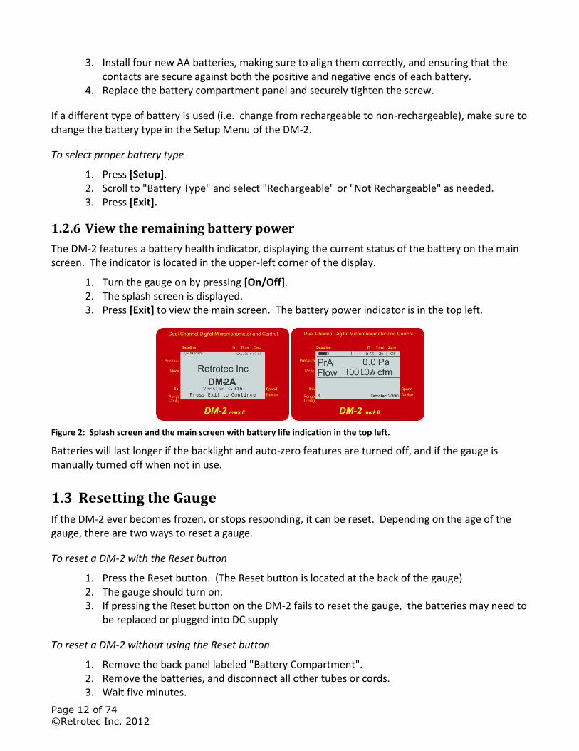
1.2.6 View the remaining battery power
The DM-2 features a battery health indicator, displaying the current status of the battery on the main screen. The indicator is located in the upper-left corner of the display.
1. Turn the gauge on by pressing [On/Off]. 2. The splash screen is displayed. 3. Press [Exit] to view the main screen. The battery power indicator is in the top left.
Figure 2: Splash screen and the main screen with battery life indication in the top left.
Batteries will last longer if the backlight and auto-zero features are turned off, and if the gauge is manually turned off when not in use.
1.3 Resetting the Gauge
If the DM-2 ever becomes frozen, or stops responding, it can be reset. Depending on the age of the gauge, there are two ways to reset a gauge.
To reset a DM-2 with the Reset button
1. Press the Reset button. (The Reset button is located at the back of the gauge) 2. The gauge should turn on. 3. If pressing the Reset button on the DM-2 fails to reset the gauge, the batteries may need to
be replaced or plugged into DC supply
To reset a DM-2 without using the Reset button
1. Remove the back panel labeled "Battery Compartment". 2. Remove the batteries, and disconnect all other tubes or cords. 3. Wait five minutes.
Page 13 of 74
©Retrotec Inc. 2012
4. Re-install the batteries.
1.4 Screen Contrast
Older model DM-2 gauges include the ability to change the screen contrast in order to improve visibility in different light conditions. Newer models have the voltage to the screen regulated so the contrast adjustment is not necessary.
To change the screen contrast
1. If required, insert a small Phillips head screwdriver into the hole on the back marked "LCD Contrast".
2. Adjust the dial until the desired screen contrast is achieved.
Page 14 of 74
©Retrotec Inc. 2012
2 DM-2 Keypad Functions
The DM-2 Keypad has 14 keys which control all of the DM-2 functions.
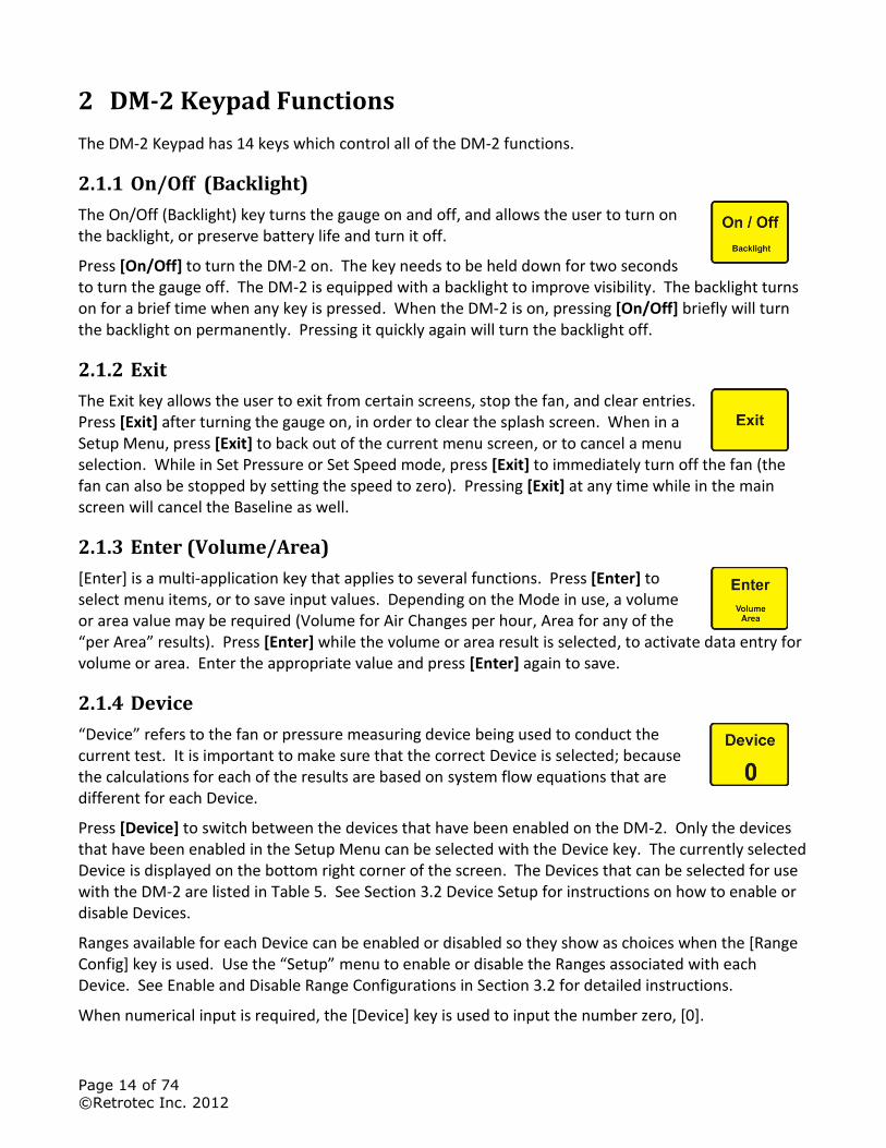
2.1.1 On/Off (Backlight)
The On/Off (Backlight) key turns the gauge on and off, and allows the user to turn on the backlight, or preserve battery life and turn it off.
Press [On/Off] to turn the DM-2 on. The key needs to be held down for two seconds to turn the gauge off. The DM-2 is equipped with a backlight to improve visibility. The backlight turns on for a brief time when any key is pressed. When the DM-2 is on, pressing [On/Off] briefly will turn the backlight on permanently. Pressing it quickly again will turn the backlight off.
2.1.2 Exit
The Exit key allows the user to exit from certain screens, stop the fan, and clear entries. Press [Exit] after turning the gauge on, in order to clear the splash screen. When in a Setup Menu, press [Exit] to back out of the current menu screen, or to cancel a menu selection. While in Set Pressure or Set Speed mode, press [Exit] to immediately turn off the fan (the fan can also be stopped by setting the speed to zero). Pressing [Exit] at any time while in the main screen will cancel the Baseline as well.
2.1.3 Enter (Volume/Area)
[Enter] is a multi-application key that applies to several functions. Press [Enter] to select menu items, or to save input values. Depending on the Mode in use, a volume or area value may be required (Volume for Air Changes per hour, Area for any of the “per Area” results). Press [Enter] while the volume or area result is selected, to activate data entry for volume or area. Enter the appropriate value and press [Enter] again to save.
2.1.4 Device
“Device” refers to the fan or pressure measuring device being used to conduct the current test. It is important to make sure that the correct Device is selected; because the calculations for each of the results are based on system flow equations that are different for each Device.
Press [Device] to switch between the devices that have been enabled on the DM-2. Only the devices that have been enabled in the Setup Menu can be selected with the Device key. The currently selected Device is displayed on the bottom right corner of the screen. The Devices that can be selected for use with the DM-2 are listed in Table 5. See Section 3.2 Device Setup for instructions on how to enable or disable Devices.
Ranges available for each Device can be enabled or disabled so they show as choices when the [Range Config] key is used. Use the “Setup” menu to enable or disable the Ranges associated with each Device. See Enable and Disable Range Configurations in Section 3.2 for detailed instructions.
When numerical input is required, the [Device] key is used to input the number zero, [0].
Page 15 of 74
©Retrotec Inc. 2012
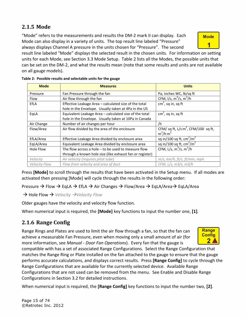
2.1.5 Mode
“Mode” refers to the measurements and results the DM-2 mark II can display. Each Mode can also display in a variety of units. The top result line labeled “Pressure” always displays Channel A pressure in the units chosen for “Pressure”. The second result line labeled “Mode” displays the selected result in the chosen units. For information on setting units for each Mode, see Section 3.3 Mode Setup. Table 2 lists all the Modes, the possible units that can be set on the DM-2, and what the results mean (note that some results and units are not available on all gauge models).
Table 2: Possible results and selectable units for the gauge
Mode Measures Units
Pressure Fan Pressure through the fan Pa, inches WC, lb/sq ft
Flow Air flow through the fan CFM, l/s, m3/s, m
3/h
EfLA Effective Leakage Area – calculated size of the total hole in the Envelope. Usually taken at 4Pa in the US
cm2, sq in, sq ft
EqLA Equivalent Leakage Area – calculated size of the total hole in the Envelope. Usually taken at 10Pa in Canada
cm2, sq in, sq ft
Air Change Number of air changes per hour /h
Flow/Area Air flow divided by the area of the enclosure CFM/ sq ft, L/s.m
2, CFM/100 sq ft,
m3/h
.m
2
EfLA/Area Effective Leakage Area divided by enclosure area sq in/100 sq ft, cm2/m
2
EqLA/Area Equivalent Leakage Area divided by enclosure area sq in/100 sq ft, cm2/m
2
Hole Flow The flow across a hole – to be used to measure flow through a known hole size (like exhaust fan or register)
CFM, L/s, m3/s, m
3/h
Velocity Air velocity (requires pitot tube) m/s, km/h, ft/s, ft/min, mph
Velocity Flow Flow from velocity and area of duct CFM, L/s, m3/s, m3/h
Press [Mode] to scroll through the results that have been activated in the Setup menu. If all modes are activated then pressing [Mode] will cycle through the results in the following order:
Pressure Flow EqLA EfLA Air Changes Flow/Area EqLA/Area EqLA/Area
Hole Flow Velocity Velocity Flow
Older gauges have the velocity and velocity flow function.
When numerical input is required, the [Mode] key functions to input the number one, [1].
2.1.6 Range Config
Range Rings and Plates are used to limit the air flow through a fan, so that the fan can achieve a measurable Fan Pressure, even when moving only a small amount of air (for more information, see Manual - Door Fan Operations). Every fan that the gauge is compatible with has a set of associated Range Configurations. Select the Range Configuration that matches the Range Ring or Plate installed on the fan attached to the gauge to ensure that the gauge performs accurate calculations, and displays correct results. Press [Range Config] to cycle through the Range Configurations that are available for the currently selected device. Available Range Configurations that are not used can be removed from the menu. See Enable and Disable Range Configurations in Section 3.2 for detailed instructions.
When numerical input is required, the [Range Config] key functions to input the number two, [2].
Page 16 of 74
©Retrotec Inc. 2012
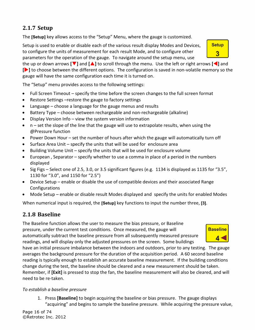
2.1.7 Setup
The [Setup] key allows access to the “Setup” Menu, where the gauge is customized.
Setup is used to enable or disable each of the various result display Modes and Devices, to configure the units of measurement for each result Mode, and to configure other parameters for the operation of the gauge. To navigate around the setup menu, use the up or down arrows [] and [] to scroll through the menu. Use the left or right arrows [] and [] to choose between the different options. The configuration is saved in non-volatile memory so the gauge will have the same configuration each time it is turned on.
The “Setup” menu provides access to the following settings:
Full Screen Timeout – specify the time before the screen changes to the full screen format
Restore Settings –restore the gauge to factory settings
Language – choose a language for the gauge menus and results
Battery Type – choose between rechargeable and non-rechargeable (alkaline)
Display Version Info – view the system version information
n – set the slope of the line that the gauge will use to extrapolate results, when using the @Pressure function
Power Down Hour – set the number of hours after which the gauge will automatically turn off
Surface Area Unit – specify the units that will be used for enclosure area
Building Volume Unit – specify the units that will be used for enclosure volume
European , Separator – specify whether to use a comma in place of a period in the numbers displayed
Sig Figs – Select one of 2.5, 3.0, or 3.5 significant figures (e.g. 1134 is displayed as 1135 for “3.5”, 1130 for “3.0”, and 1150 for “2.5”)
Device Setup – enable or disable the use of compatible devices and their associated Range Configurations
Mode Setup – enable or disable result Modes displayed and specify the units for enabled Modes
When numerical input is required, the [Setup] key functions to input the number three, [3].
2.1.8 Baseline
The Baseline function allows the user to measure the bias pressure, or Baseline pressure, under the current test conditions. Once measured, the gauge will automatically subtract the baseline pressure from all subsequently measured pressure readings, and will display only the adjusted pressures on the screen. Some buildings have an initial pressure imbalance between the indoors and outdoors, prior to any testing. The gauge averages the background pressure for the duration of the acquisition period. A 60 second baseline reading is typically enough to establish an accurate baseline measurement. If the building conditions change during the test, the baseline should be cleared and a new measurement should be taken. Remember, if [Exit] is pressed to stop the fan, the baseline measurement will also be cleared, and will need to be re-taken.
To establish a baseline pressure
1. Press [Baseline] to begin acquiring the baseline or bias pressure. The gauge displays “acquiring” and begins to sample the baseline pressure. While acquiring the pressure value,
Page 17 of 74
©Retrotec Inc. 2012
the gauge will continuously display the updated average pressure, and the sampling duration on the screen. The more the pressure is fluctuating, the longer the baseline will be sampled for.
2. Press [Enter] to accept the current measurement, usually after approximately 60 seconds. If there is a lot of fluctuation, let the baseline acquire for longer than 60 seconds. The current baseline measurement, and the time taken to acquire it, is displayed at the bottom of the Main Screen.
3. Pressing [Exit] will clear the measurement.
When numerical input is required, the [Baseline] key functions to input the number four, [4].
2.1.9 Time Avg
When Time Averaging is active, the gauge will display results and pressures that are averaged over the time period selected, on both channels. Regardless of the averaging value, the display will update with a new value every second. This can provide significantly more accurate results.
The gauge includes nine time averaging settings. Press [Time Avg] to scroll through the following time averaging settings: Off, 1s, 2s, 4s, 8s, 10s, 20s, 1m, and 2m.
Caution: When changing the fan speed, set pressure, or taking a reading after making any other changes, wait for twice the time averaging period to elapse before taking a reading. Taking a reading too quickly can lead to recording incorrect results.
Notice that the [Time Avg] key is located in the middle of all the arrow keys on the keypad. As a user friendly feature, while in the Setup Menu, the [Time Avg] key can be used to select menu items, just as you would using the [Enter] key.
When numerical input is required, the [Time Avg] key functions to input the number five, [5].
2.1.10 Auto Zero
Over time, the reading on Channel A and Channel B will start to drift away from zero. The longer the gauge is turned on, the larger this error can become. With Auto Zero on, the gauge will automatically zero the gauge every 8 seconds. In general, the DM-2 should be used with auto zero feature on. However, the function does consume extra battery power. Turning auto zero on, only at the start of each data acquisition cycle, will maximize battery life, gauge performance and data transfer rates.
Press [Auto Zero] to turn the Auto Zero function on or off.
When numerical input is required, the [Auto Zero] key functions to input the number six, [6].
2.1.11 Set Pressure
The gauge can automatically control the fan speed on Retrotec systems to achieve a user chosen building pressure. This is the easiest method to achieve a specific test pressure.
To use the Set Pressure function
Page 18 of 74
©Retrotec Inc. 2012
1. Press [Set Pressure] to activate the automatic control. Input the desired building pressure using the DM-2 keypad and press [Enter] to start the fan.
2. The fan will accelerate until the input pressure has been reached, or the fan reaches 100% speed. The fan will continue to hold at that pressure, regardless of changes to the enclosure or room (i.e. opening/closing windows and doors, HVAC on/off, sealing, etc.).
3. Press [Exit] to stop the fan, and cancel the Set Pressure.
If the pressure is set to “0” Pa, the gauge will adjust the fan speed to bring the existing pressure to zero. This can be used to neutralize pressures during specific tests. See the Retrotec DucTester Operation & Testing manual for an example.
When numerical input is required, the [Set Pressure] key functions to input the number seven, [7].
2.1.12 Set Speed
The gauge can automatically control the fan speed on Retrotec systems to achieve a specific user-defined fan speed.
To use the Set Speed function
1. Press [Set Speed] to activate the automatic control. 2. Input the desired speed using the DM-2 keypad. Speed is input as a percentage, and can be
any value from 1-100. 3. Press [Enter] to start the fan. The fan will accelerate until the desired speed is achieved. 4. Press [Exit] to stop the fan and cancel the Set Speed, or press [Set Speed] [0] [Enter] to stop
the fan.
When numerical input is required, the [Set Speed] key functions to input the number eight, [8].
2.1.13 Jog/Hold
The [Jog/Hold] key has two functions, Holding the display and Jogging the fan speed:
2.1.13.1 Hold
Freezes the display with the data currently displayed on the screen. Nothing will change until the [Jog/Hold] key is pressed again to clear "Hold".
Can be activated at any time.
Allows the recording of instananeous results (eg. Flow, EqLA, PrB at precisely the same time)
Hold will also hold the Speed Control signal to the fan without allowing it to vary up or down. The signal will be held until [Exit] is pressed which will shut off the fan.
The screen will display either "- - - - " or "Hold", unless it is doing a Set Speed or Set Pressure when it will display either "- - - - ", "Jog" or "Hold".
To activate Hold:
1. Press [Jog/Hold] until "Hold" appears on the screen to freeze the screen and lock the data currently displayed.
2. Press [Jog/Hold] again until "----" is displayed to unlock the screen.
Page 19 of 74
©Retrotec Inc. 2012
2.1.13.2 Jog
Jog functions differently depending on whether the gauge is setting pressure or setting speed.
Enables the keypad arrows [] or []to adjust the Set Speed or Set Pressure up or down much like a traditional remote control.
The screen will display either "- - - - ", "Jog" or "Hold" (when in Set Speed or Set Pressure mode).
When not in Set Speed or Set Pressure mode, the DM-2 will not enter Jog mode (but Hold mode can be activated at any time).
In Set Speed
1. Press [Jog/Hold] until "Jog" appears on screen. 2. Press [] or [] to increase or decrease the set speed in 1% increments. 3. Press and hold [] or [] to increase or decrease the set speed in 5% increments. 4. Press [Jog/Hold] again until "----" is displayed to resume normal operation.
In Set Pressure
1. Press [Jog/Hold] until "Jog" appears on screen. 2. Press [] or [] to increase or decrease the set pressure in increments of 5 Pa, 0.02 in WC,
or 0.105 lbs/sq ft. 3. Press and hold [] or [] to increase or decrease the set pressure in increments of 10 Pa,
0.04 in WC, or 0.21 lb/sq ft. 4. Press [Jog/Hold] again until "----" is displayed to resume normal operation.
When numerical input is required, the [Jog/Hold] key functions to input the number nine, [9].
2.1.14 @ Pressure
The [@ Pressure] key asks the DM-2 to calculate a result that would be achieved, if the desired test pressure were measured. The measured pressure will almost always be at least slightly over, or under, the exact test pressure making it difficult to report results that are standardised for a specific pressure. The [@ Pressure] function performs a calculation called "extrapolation" which analyzes the currently measured results, and displays the results as if the exact test pressure was achieved.
Press [@ Pressure] to toggle the gauge pressure extrapolation function on and off. The test pressure that is being extrapolated to is configured in the Setup Menu.
Note: While the gauge is capable of extrapolating to any pressure, it is most accurate when the actual building pressure is closer to the desired extrapolation pressure.
The @ Pressure function provides unique advantages over un-extrapolated results:
There is no need to achieve an exact test pressure.
The results on the screen will be very stable since results are extrapolated to a specific pressure.
Results can be obtained, even if the test pressure cannot be reached, as long as the pressure actually achieved is within 10% of the desired test pressure.
In Set Speed mode
Page 20 of 74
©Retrotec Inc. 2012
1. Press [@ Pressure] to view the results at a particular pressure, as set in the Setup Menu. The units will change to indicate that @ Pressure is on (e.g. [email protected]).
2. Press [@ Pressure] again to view the current (non-extrapolated) results. The units will change to indicate that @ Pressure is off (e.g. CFM).
In Set Pressure mode
1. Press [@ Pressure] once to view the results at the current Set Pressure value. The units will change to indicate that @ Pressure is on (e.g. [email protected]).
2. Press [@ Pressure] again to view the results at the @ Pressure, as set in the Setup Menu. The @ Pressure value will change (e.g. [email protected]).
3. Press [@ Pressure] again to view the current (non-extrapolated) results. The units will change to indicate that @ Pressure is off (e.g. CFM).
It is important to understand how to use this feature properly, as inaccurate results are likely if it is used incorrectly. The extrapolation feature works by estimating a typical leakage constant, and using it to calculate the results at the desired pressure. In general, if the desired test pressure is within +/- 10% of the actual measured pressure, the @ Pressure will be accurate enough to record. This function should only be turned on and made active when in the appropriate situation – do not leave it on for all tests as this may lead to inaccuracies. Try the examples below to familiarize yourself with the versatility of this function.
Example #1 - Inaccuracy
A 50 Pa building pressure is desired, but only 20 Pa can be reached (due to severe leakiness). In this instance, the extrapolated results for flow “@ 50 Pa” do not represent the reality of the testing conditions and might be highly inaccurate.
In the same situation, a 45 Pa building pressure is achieved. The extrapolated “@ 50 Pa” pressure is now much more accurate, and provides an acceptable result.
Example #2 – Cannot reach desired pressure in Set Speed mode
With the fan set at 100% speed, a building pressure of 46 Pa is reached. Press [@ Pressure] once and the flow that would occur at the default pressure (usually 50 Pa) is displayed. Each time the key is pressed, the results alternate between displaying “CFM” and “CFM @50Pa”. This Default Pressure of 50 Pa can be changed in the Setup menu and will usually be the one you want results at most of the time.
Example #3 – Display results at any pressure.
If you wish to display results at a different pressure, the fastest method is to use the [Set Pressure] key. Press [Set Pressure] [75] and now pressing the [@ Pressure] key will cycle between; “CFM”, “CFM @50Pa”, and “CFM @75Pa”.
When numerical input is required, the [@ Pressure] key functions to input the decimal point [.].
Page 21 of 74
©Retrotec Inc. 2012
3 Set the Gauge up with only the Devices and results you use regularly
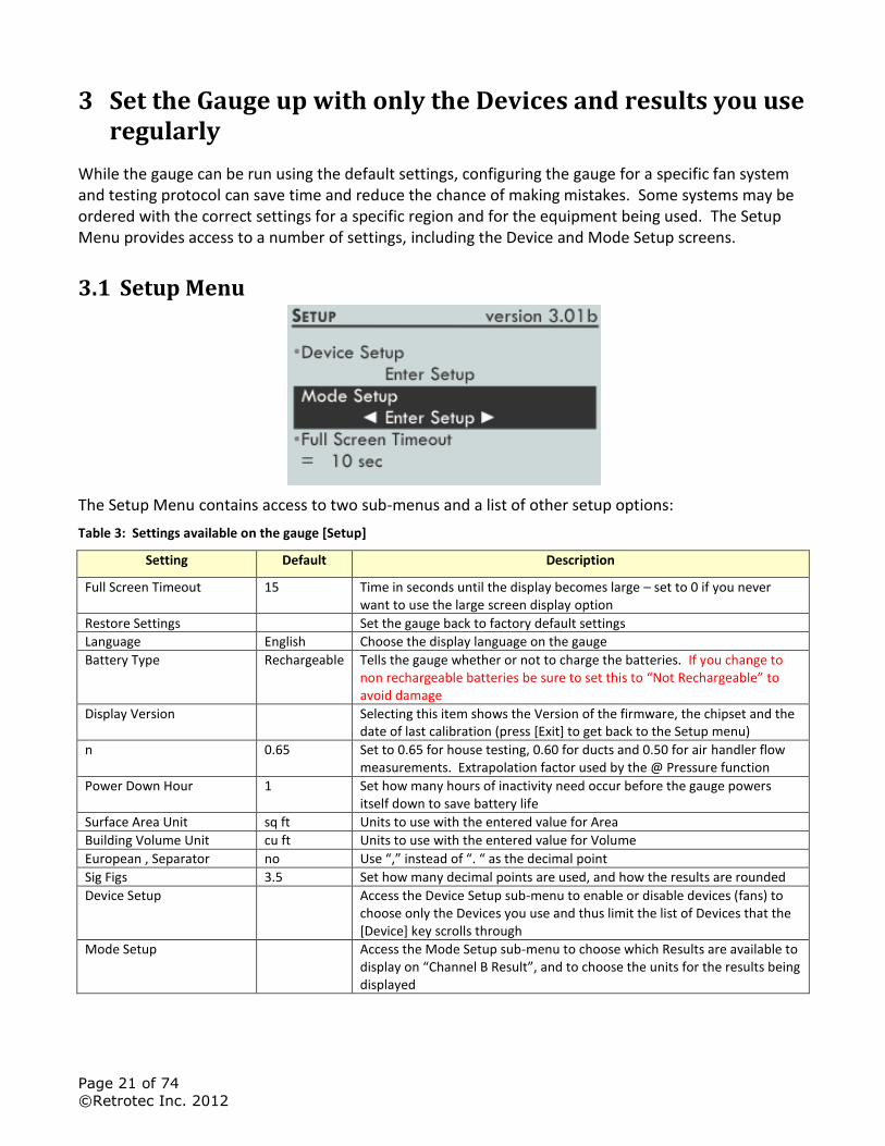
While the gauge can be run using the default settings, configuring the gauge for a specific fan system and testing protocol can save time and reduce the chance of making mistakes. Some systems may be ordered with the correct settings for a specific region and for the equipment being used. The Setup Menu provides access to a number of settings, including the Device and Mode Setup screens.
3.1 Setup Menu
The Setup Menu contains access to two sub-menus and a list of other setup options:
Table 3: Settings available on the gauge [Setup]
Setting Default Description
Full Screen Timeout 15 Time in seconds until the display becomes large – set to 0 if you never want to use the large screen display option
Restore Settings Set the gauge back to factory default settings
Language English Choose the display language on the gauge
Battery Type Rechargeable Tells the gauge whether or not to charge the batteries. If you change to non rechargeable batteries be sure to set this to “Not Rechargeable” to avoid damage
Display Version Selecting this item shows the Version of the firmware, the chipset and the date of last calibration (press [Exit] to get back to the Setup menu)
n 0.65 Set to 0.65 for house testing, 0.60 for ducts and 0.50 for air handler flow measurements. Extrapolation factor used by the @ Pressure function
Power Down Hour 1 Set how many hours of inactivity need occur before the gauge powers itself down to save battery life
Surface Area Unit sq ft Units to use with the entered value for Area
Building Volume Unit cu ft Units to use with the entered value for Volume
European , Separator no Use “,” instead of “. “ as the decimal point
Sig Figs 3.5 Set how many decimal points are used, and how the results are rounded
Device Setup Access the Device Setup sub-menu to enable or disable devices (fans) to choose only the Devices you use and thus limit the list of Devices that the [Device] key scrolls through
Mode Setup Access the Mode Setup sub-menu to choose which Results are available to display on “Channel B Result”, and to choose the units for the results being displayed
Page 22 of 74
©Retrotec Inc. 2012
Notice that the [Time Avg] key is located in the middle of all the arrow keys on the keypad. As a user friendly feature, while in the Setup Menu, the [Time Avg] key can be used to select menu items, just as you would using the [Enter] key.
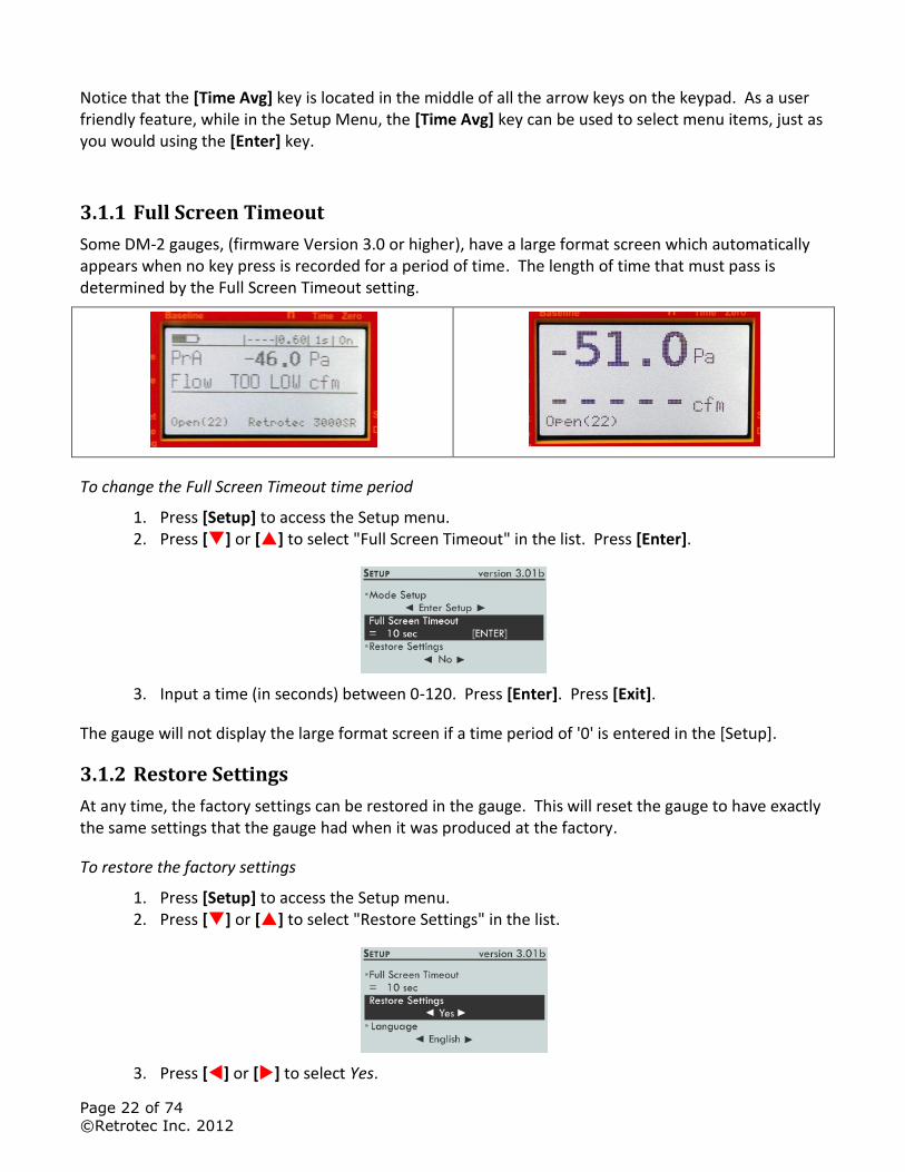
3.1.1 Full Screen Timeout
Some DM-2 gauges, (firmware Version 3.0 or higher), have a large format screen which automatically appears when no key press is recorded for a period of time. The length of time that must pass is determined by the Full Screen Timeout setting.
To change the Full Screen Timeout time period
1. Press [Setup] to access the Setup menu. 2. Press [] or [] to select "Full Screen Timeout" in the list. Press [Enter].
3. Input a time (in seconds) between 0-120. Press [Enter]. Press [Exit].
The gauge will not display the large format screen if a time period of '0' is entered in the [Setup].
3.1.2 Restore Settings
At any time, the factory settings can be restored in the gauge. This will reset the gauge to have exactly the same settings that the gauge had when it was produced at the factory.
To restore the factory settings
1. Press [Setup] to access the Setup menu. 2. Press [] or [] to select "Restore Settings" in the list.
3. Press [] or [] to select Yes.
Page 23 of 74
©Retrotec Inc. 2012
3.1.3 Language
The gauge can display information in the following languages: English, French, German, Norwegian, Swedish, and Latvian.
To change the language
1. Press [Setup] to access the Setup menu. 2. Press [] or [] to select "Language" in the list.
3. Press [] or [] to select the desired language.
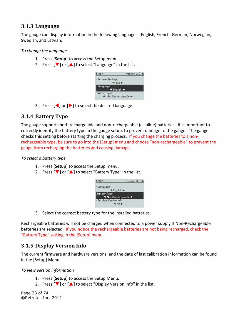
3.1.4 Battery Type
The gauge supports both rechargeable and non-rechargeable (alkaline) batteries. It is important to correctly identify the battery type in the gauge setup, to prevent damage to the gauge. The gauge checks this setting before starting the charging process. If you change the batteries to a non-rechargeable type, be sure to go into the [Setup] menu and choose “non-rechargeable” to prevent the gauge from recharging the batteries and causing damage.
To select a battery type
1. Press [Setup] to access the Setup menu. 2. Press [] or [] to select "Battery Type" in the list.
3. Select the correct battery type for the installed batteries.
Rechargeable batteries will not be charged when connected to a power supply if Non-Rechargeable batteries are selected. If you notice the rechargeable batteries are not being recharged, check the “Battery Type” setting in the [Setup] menu.
3.1.5 Display Version Info
The current firmware and hardware versions, and the date of last calibration information can be found in the [Setup] Menu.
To view version information
1. Press [Setup] to access the Setup Menu. 2. Press [] or [] to select "Display Version Info" in the list.
Page 24 of 74
©Retrotec Inc. 2012
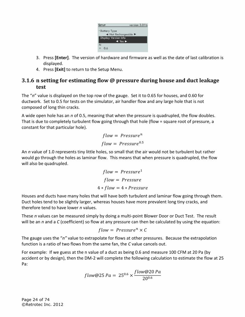
3. Press [Enter]. The version of hardware and firmware as well as the date of last calibration is displayed.
4. Press [Exit] to return to the Setup Menu.
3.1.6 n setting for estimating flow @ pressure during house and duct leakage test
The “n” value is displayed on the top row of the gauge. Set it to 0.65 for houses, and 0.60 for ductwork. Set to 0.5 for tests on the simulator, air handler flow and any large hole that is not composed of long thin cracks.
A wide open hole has an n of 0.5, meaning that when the pressure is quadrupled, the flow doubles. That is due to completely turbulent flow going through that hole (flow = square root of pressure, a constant for that particular hole).
An n value of 1.0 represents tiny little holes, so small that the air would not be turbulent but rather would go through the holes as laminar flow. This means that when pressure is quadrupled, the flow will also be quadrupled.
Houses and ducts have many holes that will have both turbulent and laminar flow going through them. Duct holes tend to be slightly larger, whereas houses have more prevalent long tiny cracks, and therefore tend to have lower n values.
These n values can be measured simply by doing a multi-point Blower Door or Duct Test. The result will be an n and a C (coefficient) so flow at any pressure can then be calculated by using the equation:
The gauge uses the “n” value to extrapolate for flows at other pressures. Because the extrapolation function is a ratio of two flows from the same fan, the C value cancels out.
For example: If we guess at the n value of a duct as being 0.6 and measure 100 CFM at 20 Pa (by accident or by design), then the DM-2 will complete the following calculation to estimate the flow at 25 Pa:
Page 25 of 74
©Retrotec Inc. 2012
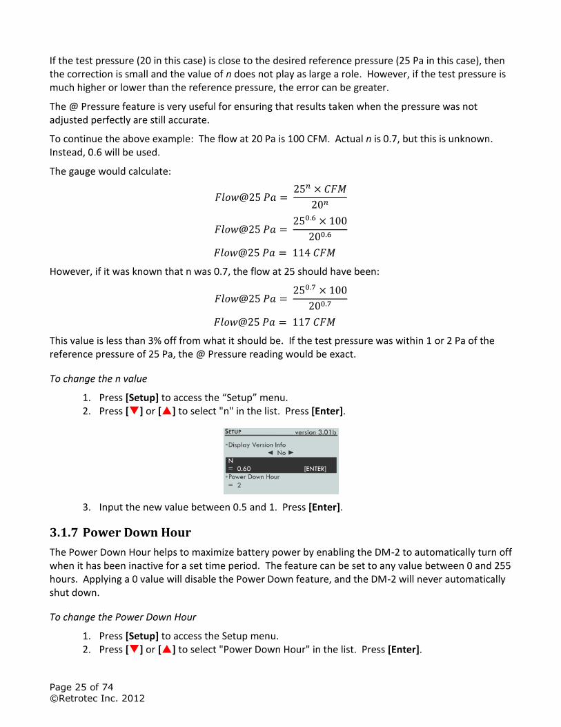
If the test pressure (20 in this case) is close to the desired reference pressure (25 Pa in this case), then the correction is small and the value of n does not play as large a role. However, if the test pressure is much higher or lower than the reference pressure, the error can be greater.
The @ Pressure feature is very useful for ensuring that results taken when the pressure was not adjusted perfectly are still accurate.
To continue the above example: The flow at 20 Pa is 100 CFM. Actual n is 0.7, but this is unknown. Instead, 0.6 will be used.
The gauge would calculate:
However, if it was known that n was 0.7, the flow at 25 should have been:
This value is less than 3% off from what it should be. If the test pressure was within 1 or 2 Pa of the reference pressure of 25 Pa, the @ Pressure reading would be exact.
To change the n value
1. Press [Setup] to access the “Setup” menu. 2. Press [] or [] to select "n" in the list. Press [Enter].
3. Input the new value between 0.5 and 1. Press [Enter].
3.1.7 Power Down Hour
The Power Down Hour helps to maximize battery power by enabling the DM-2 to automatically turn off when it has been inactive for a set time period. The feature can be set to any value between 0 and 255 hours. Applying a 0 value will disable the Power Down feature, and the DM-2 will never automatically shut down.
To change the Power Down Hour
1. Press [Setup] to access the Setup menu. 2. Press [] or [] to select "Power Down Hour" in the list. Press [Enter].
Page 26 of 74
©Retrotec Inc. 2012
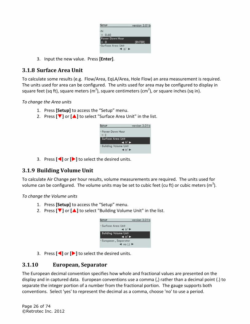
3. Input the new value. Press [Enter].
3.1.8 Surface Area Unit
To calculate some results (e.g. Flow/Area, EqLA/Area, Hole Flow) an area measurement is required. The units used for area can be configured. The units used for area may be configured to display in square feet (sq ft), square meters (m2), square centimeters (cm2), or square inches (sq in).
To change the Area units
1. Press [Setup] to access the “Setup” menu. 2. Press [] or [] to select "Surface Area Unit" in the list.
3. Press [] or [] to select the desired units.
3.1.9 Building Volume Unit
To calculate Air Change per hour results, volume measurements are required. The units used for volume can be configured. The volume units may be set to cubic feet (cu ft) or cubic meters (m3).
To change the Volume units
1. Press [Setup] to access the “Setup” menu. 2. Press [] or [] to select "Building Volume Unit" in the list.
3. Press [] or [] to select the desired units.
3.1.10 European, Separator
The European decimal convention specifies how whole and fractional values are presented on the display and in captured data. European conventions use a comma (,) rather than a decimal point (.) to separate the integer portion of a number from the fractional portion. The gauge supports both conventions. Select 'yes' to represent the decimal as a comma, choose 'no' to use a period.
Page 27 of 74
©Retrotec Inc. 2012
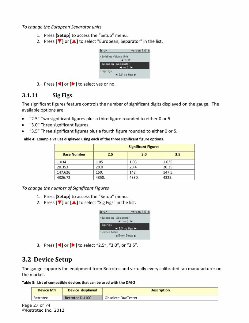
To change the European Separator units
1. Press [Setup] to access the “Setup” menu. 2. Press [] or [] to select "European, Separator" in the list.
3. Press [] or [] to select yes or no.
3.1.11 Sig Figs
The significant figures feature controls the number of significant digits displayed on the gauge. The available options are:
“2.5” Two significant figures plus a third figure rounded to either 0 or 5.
“3.0” Three significant figures.
“3.5” Three significant figures plus a fourth figure rounded to either 0 or 5.
Table 4: Example values displayed using each of the three significant figure options.
Significant Figures
Base Number 2.5 3.0 3.5
1.034 1.05 1.03 1.035
20.353 20.0 20.4 20.35
147.626 150. 148. 147.5
4326.72 4350. 4330. 4325.
To change the number of Significant Figures
1. Press [Setup] to access the “Setup” menu. 2. Press [] or [] to select "Sig Figs" in the list.
3. Press [] or [] to select “2.5”, “3.0”, or “3.5”.
3.2 Device Setup
The gauge supports fan equipment from Retrotec and virtually every calibrated fan manufacturer on the market.
Table 5: List of compatible devices that can be used with the DM-2
Device Mfr Device displayed Description
Retrotec Retrotec DU100 Obsolete DucTester
Page 28 of 74
©Retrotec Inc. 2012
Device Mfr Device displayed Description
*Retrotec DU200 Model 200 fan, Q32 DucTester
Retrotec 600/700 Obsolete fans
Retrotec 800/900
*Retrotec 1000 Model 1000 systems with 0.75 hp yellow wheel rim style fans
Retrotec 2000 Model Q46 and Q56 systems with 0.75 hp yellow foam core fan. Same curves as 1000.
Retrotec 3000 Older Model Q4E, Q5E and QMG systems with 2 hp yellow foam core Door Fan. Same curves as 1000.
Retrotec 3000SR Model Q4E, Q5E and QMG systems with 2 hp yellow foam core Door Fan – all fans are self-referencing (have green tube)
TEC Mn Duct Blaster B Duct testing fan
TEC Mn Model 3 (120V)
0.75 hp black wheel rim style fan TEC Mn Model 3 (240V)
TEC Mn Model 4 (240V)
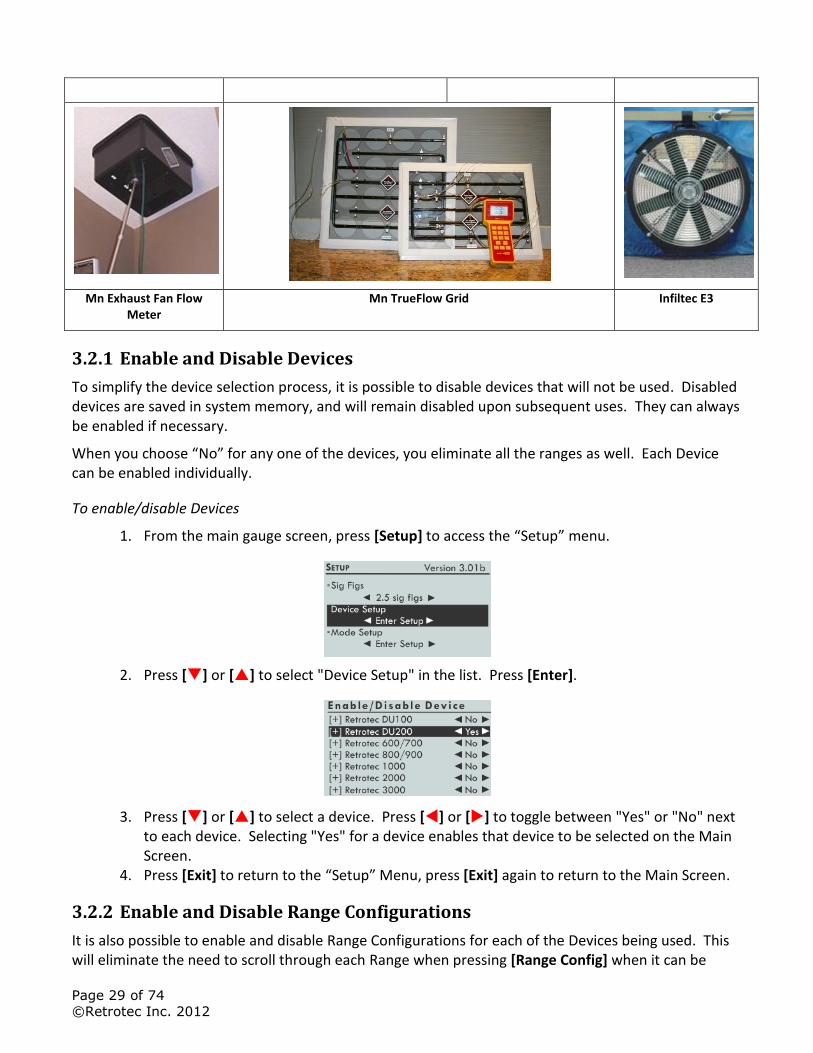
TEC Exhaust Fan Flow Meter
Exhaust Fan Flow Meter – measures air flow through residential exhaust fans between 10 and 124 CFM. This Device does not currently work on many DM-2s since the minimum pressure is set to 10 Pa and typical pressures inside the Exhaust fan box are typically 1 to 8 Pa. The pressure in Pascals and table from the mfr must be used to determine flow.
TEC TrueFlow® True Flow Grid – measures flow through a residential air handler
Infiltec Infiltec E3 0.75 hp black wheel rim style fan
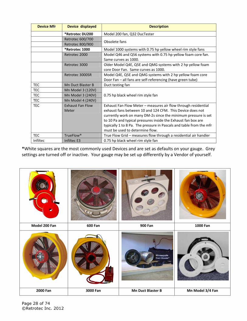
*White squares are the most commonly used Devices and are set as defaults on your gauge. Grey settings are turned off or inactive. Your gauge may be set up differently by a Vendor of yourself.
Model 200 Fan 600 Fan 900 Fan 1000 Fan
2000 Fan 3000 Fan Mn Duct Blaster B Mn Model 3/4 Fan
Page 29 of 74
©Retrotec Inc. 2012
Mn Exhaust Fan Flow Meter
Mn TrueFlow Grid Infiltec E3
3.2.1 Enable and Disable Devices
To simplify the device selection process, it is possible to disable devices that will not be used. Disabled devices are saved in system memory, and will remain disabled upon subsequent uses. They can always be enabled if necessary.
When you choose “No” for any one of the devices, you eliminate all the ranges as well. Each Device can be enabled individually.
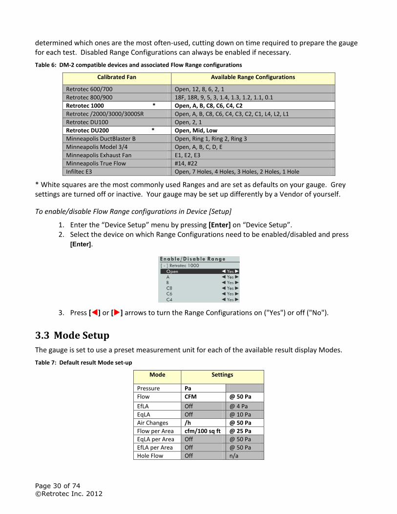
To enable/disable Devices
1. From the main gauge screen, press [Setup] to access the “Setup” menu.
2. Press [] or [] to select "Device Setup" in the list. Press [Enter].
3. Press [] or [] to select a device. Press [] or [] to toggle between "Yes" or "No" next to each device. Selecting "Yes" for a device enables that device to be selected on the Main Screen.
4. Press [Exit] to return to the “Setup” Menu, press [Exit] again to return to the Main Screen.
3.2.2 Enable and Disable Range Configurations
It is also possible to enable and disable Range Configurations for each of the Devices being used. This will eliminate the need to scroll through each Range when pressing [Range Config] when it can be
Page 30 of 74
©Retrotec Inc. 2012
determined which ones are the most often-used, cutting down on time required to prepare the gauge for each test. Disabled Range Configurations can always be enabled if necessary.
Table 6: DM-2 compatible devices and associated Flow Range configurations
Calibrated Fan Available Range Configurations
Retrotec 600/700 Open, 12, 8, 6, 2, 1
Retrotec 800/900 18F, 18R, 9, 5, 3, 1.4, 1.3, 1.2, 1.1, 0.1
Retrotec 1000 * Open, A, B, C8, C6, C4, C2
Retrotec /2000/3000/3000SR Open, A, B, C8, C6, C4, C3, C2, C1, L4, L2, L1
Retrotec DU100 Open, 2, 1
Retrotec DU200 * Open, Mid, Low
Minneapolis DuctBlaster B Open, Ring 1, Ring 2, Ring 3
Minneapolis Model 3/4 Open, A, B, C, D, E
Minneapolis Exhaust Fan E1, E2, E3
Minneapolis True Flow #14, #22
Infiltec E3 Open, 7 Holes, 4 Holes, 3 Holes, 2 Holes, 1 Hole
* White squares are the most commonly used Ranges and are set as defaults on your gauge. Grey settings are turned off or inactive. Your gauge may be set up differently by a Vendor of yourself.
To enable/disable Flow Range configurations in Device [Setup]
1. Enter the “Device Setup” menu by pressing [Enter] on “Device Setup”. 2. Select the device on which Range Configurations need to be enabled/disabled and press
[Enter].
3. Press [] or [] arrows to turn the Range Configurations on ("Yes") or off ("No").
3.3 Mode Setup
The gauge is set to use a preset measurement unit for each of the available result display Modes.
Table 7: Default result Mode set-up
Mode Settings
Pressure Pa
Flow CFM @ 50 Pa
EfLA Off @ 4 Pa
EqLA Off @ 10 Pa
Air Changes /h @ 50 Pa
Flow per Area cfm/100 sq ft @ 25 Pa
EqLA per Area Off @ 50 Pa
EfLA per Area Off @ 50 Pa
Hole Flow Off n/a

Page 31 of 74
©Retrotec Inc. 2012
White squares in the table are the most commonly used Modes and are set as defaults on your gauge. Grey settings are turned off by default so are inactive until they are turned back on. Your gauge may be set up differently when you receive it. Air Changes at 50Pa, which is commonly called ACH50 or n50 is used with Blower Doors to test house leakage. “CFM/100 sq ft” is commonly used when testing ducts to International Energy Conservation Codes (IECC) in most US States.
The gauge supports a number of calculations which can simplify the testing procedure. Some of these may be useful for specific testing needs. Use Mode Setup to customize the gauge to enable display of only the specific results that will be used regularly. The configuration is permanently saved, but can be changed at any time and the new configuration will be permanently saved. Once configured, pressing the [Mode] key on the gauge will cycle through only those Modes that are enabled in the “Mode Setup” menu.
To configure Modes:
1. Press [Setup] to access the “Setup” menu.
2. Press [] or [] to select "Mode Setup" in the list. Press [Enter].
3. Press [] or [] to select a Mode. Press [] or [] to select the units associated with each mode. Select 'off' to disable that mode on the Main Screen.
4. Some modes have an associated “@ Pressure”. To change it, press [] or [] to highlight the associated "@ Pressure", and press [Enter]. Input the new value using the number keys on the keypad, and press [Enter] again.
Page 32 of 74
©Retrotec Inc. 2012
4 Understand the Pressure Gauge
A high-performance digital differential pressure gauge offers a number of advantages over analog counterparts:
Easy to read
Pressure sensors have greater sensitivity
Performs calculations that would otherwise need to be done manually
A digital gauge, therefore, can save a lot of testing time with proper use of its functions.
4.1 Differential Pressure
Each gauge contains two pressure transducers, which each measure the difference in pressure between two ports. The most common units of measurement are Pascals (Pa), but inches of water column (in WC) and pounds per square foot (psf) are also available. Inches of water column is the easiest to visualize because one inch water column (1 in WC) is the amount of pressure required to suck water up a straw to a height of one inch.
One inch of water column (in WC) = 249 Pa = 5.2 psf
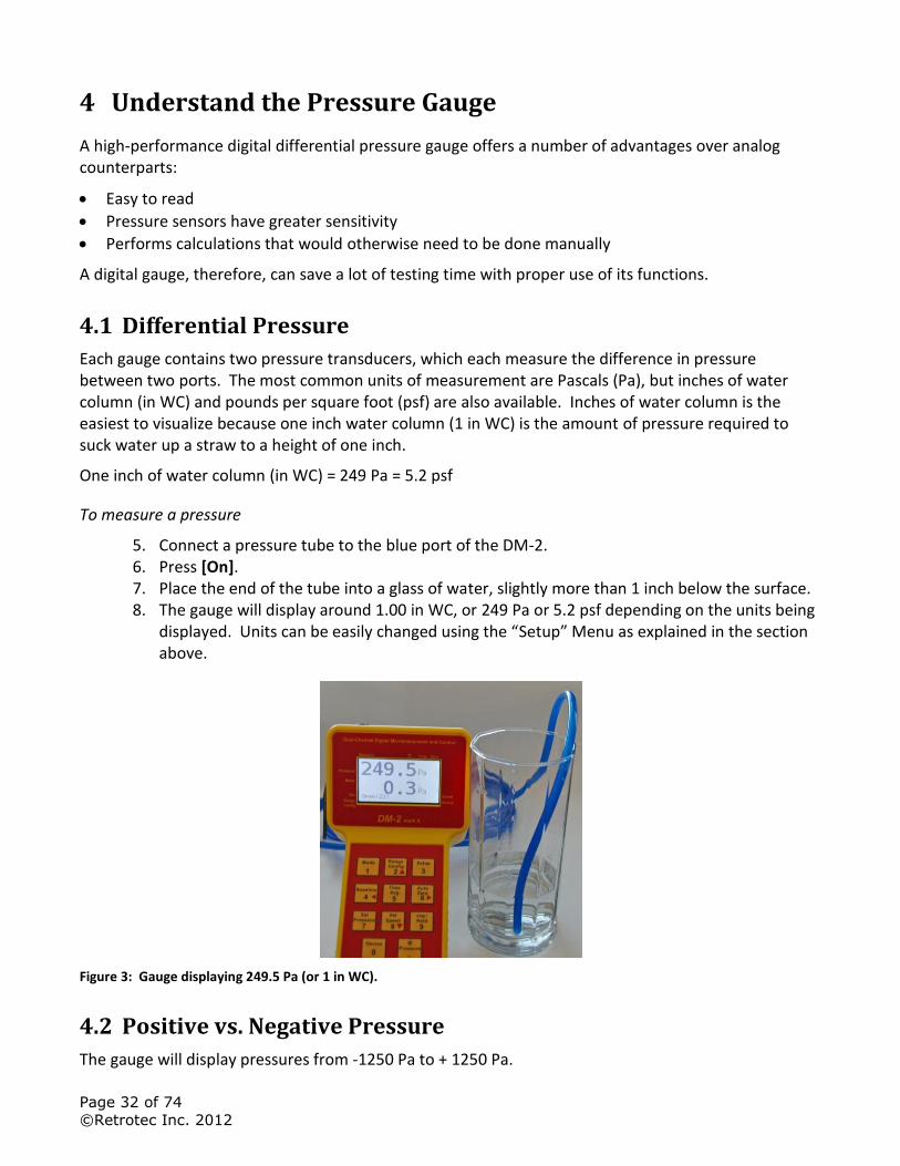
To measure a pressure
5. Connect a pressure tube to the blue port of the DM-2. 6. Press [On]. 7. Place the end of the tube into a glass of water, slightly more than 1 inch below the surface. 8. The gauge will display around 1.00 in WC, or 249 Pa or 5.2 psf depending on the units being
displayed. Units can be easily changed using the “Setup” Menu as explained in the section above.
Figure 3: Gauge displaying 249.5 Pa (or 1 in WC).
4.2 Positive vs. Negative Pressure
The gauge will display pressures from -1250 Pa to + 1250 Pa.
Page 33 of 74
©Retrotec Inc. 2012
A higher pressure on the positive (“Input”) port than on the negative (“Reference”) port displays a positive pressure on the gauge. Alternatively, a higher pressure on the negative (“Reference”) port than on the positive (“Input”) port displays a negative pressure.
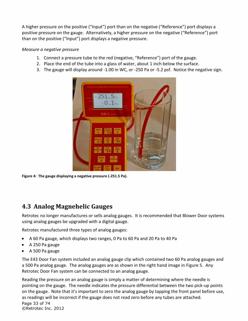
Measure a negative pressure
1. Connect a pressure tube to the red (negative, “Reference”) port of the gauge. 2. Place the end of the tube into a glass of water, about 1 inch below the surface. 3. The gauge will display around -1.00 in WC, or -250 Pa or -5.2 psf. Notice the negative sign.
Figure 4: The gauge displaying a negative pressure (-251.5 Pa).
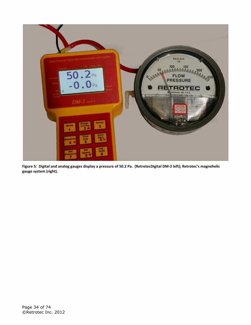
4.3 Analog Magnehelic Gauges
Retrotec no longer manufactures or sells analog gauges. It is recommended that Blower Door systems using analog gauges be upgraded with a digital gauge.
Retrotec manufactured three types of analog gauges:
A 60 Pa gauge, which displays two ranges, 0 Pa to 60 Pa and 20 Pa to 40 Pa
A 250 Pa gauge
A 500 Pa gauge
The E43 Door Fan system included an analog gauge clip which contained two 60 Pa analog gauges and a 500 Pa analog gauge. The analog gauges are as shown in the right hand image in Figure 5. Any Retrotec Door Fan system can be connected to an analog gauge.
Reading the pressure on an analog gauge is simply a matter of determining where the needle is pointing on the gauge. The needle indicates the pressure differential between the two pick-up points on the gauge. Note that it's important to zero the analog gauge by tapping the front panel before use, as readings will be incorrect if the gauge does not read zero before any tubes are attached.
Page 34 of 74
©Retrotec Inc. 2012
Figure 5: Digital and analog gauges display a pressure of 50.2 Pa. (RetrotecDigital DM-2 left); Retrotec’s magnehelic gauge system (right).
Page 35 of 74
©Retrotec Inc. 2012
5 Reduce Bias pressures, static or fluctuating
Wind blowing across the tip of a tube will cause a significant pressure to appear on the gauge. High fluctuations of bias (baseline) pressures on the gauge (greater than 2 Pa) are a good indication that wind may be a large source of error.
Another thing to notice when the wind is blowing is that it’s very difficult to establish and maintain the test pressure. In windy conditions, the readings on the house/room gauge will fluctuate. For example, when trying to establish 50 Pa, the wind will cause that pressure to go up to 55 Pa and down to 45 Pa, making it very difficult to take a reading.
There are other reasons a large Bias or Baseline pressure can appear on the gauge and these should be eliminated first before assuming wind is causing the problem. If the tube is being moved by the wind, a large rapidly fluctuating pressure will appear but can easily be eliminated by taping or tying down the tube. Next, a large and steady pressure of 10 to 70 Pa will appear if the tube end has touched water and a drop has sealed off the end. Stepping on the tube, or pinching the tube will induce a Bias pressure, so ensure that tubes are not pinched and are located away from walkways.
If air inside the exterior heats up due to the Sun shining on it and if the tube end is above or below the point where it leaves the enclosure, a stack pressure will build up inside the tube that will create a steady pressure that may increase as the tube gets hotter.
Reduce fluctuating pressures created by wind
There are two types of pressure that wind creates, stagnation pressure and velocity pressure.
Stagnation pressure- is felt over a large area in the windward side and for several feet from the building and is a result of the air stacking up due to the wind velocity. The wind's velocity is converted to a pressure.
Stagnation pressures are reduced by moving the outdoor pickup point about 15 feet from the building or away from any object that the wind will strike. Place the tube at ground level with a flat plate covering the tube. The pressure field around the building changes from side to side and because the wind direction varies somewhat; using two pickup points at least 20 feet apart will reduce these fluctuations.
Velocity pressure – is caused by the velocity impinging in the end of the tube and converting itself into a pressure at the tube end.
Wind velocity is always lower on the leeward side of the building. Moving pickup points away from the windward side reduces the magnitude of wind induced pressures.
Wind velocity increases with height from the ground, so placing our pickup points at ground level reduces the magnitude of fluctuations.
Covering the end of the tube without blocking it helps because the static pressure is reduced. Pop bottles or other containers help. Some testers dig holes to place the tube in. All these methods work. Flat plates on the ground work best because the openings face all directions, and the pickup point is low down. A T works well too.
Combining these methods gives a list you can go by if Baseline pressures are above 2 Pa or you simply want to increase repeatability. Your outdoor pressure pickup tube should:
Page 36 of 74
©Retrotec Inc. 2012
1. Be 15 feet from the building 2. Terminate in a T 3. Have 2 pickup points at least 20 feet apart attached to either side of the T 4. Each point should be covered with a flat plate or box
These steps will reduce the magnitude and variation of the Baseline pressures your gauge will see. After that, time averaging or long Baseline recordings will reduce the impact of these wind pressures. Detailed instructions for dealing with fluctuating wind can be found in Troubleshooting Error! Reference source not found..
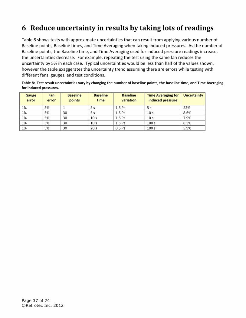
Page 37 of 74
©Retrotec Inc. 2012
6 Reduce uncertainty in results by taking lots of readings
Table 8 shows tests with approximate uncertainties that can result from applying various number of Baseline points, Baseline times, and Time Averaging when taking induced pressures. As the number of Baseline points, the Baseline time, and Time Averaging used for induced pressure readings increase, the uncertainties decrease. For example, repeating the test using the same fan reduces the uncertainty by 5% in each case. Typical uncertainties would be less than half of the values shown, however the table exaggerates the uncertainty trend assuming there are errors while testing with different fans, gauges, and test conditions.
Table 8: Test result uncertainties vary by changing the number of baseline points, the baseline time, and Time Averaging for induced pressures.
Gauge error
Fan error
Baseline points
Baseline time
Baseline variation
Time Averaging for induced pressure
Uncertainty
1% 5% 1 5 s 1.5 Pa 5 s 22%
1% 5% 30 5 s 1.5 Pa 10 s 8.6%
1% 5% 30 10 s 1.5 Pa 10 s 7.9%
1% 5% 30 10 s 1.5 Pa 100 s 6.5%
1% 5% 30 20 s 0.5 Pa 100 s 5.9%
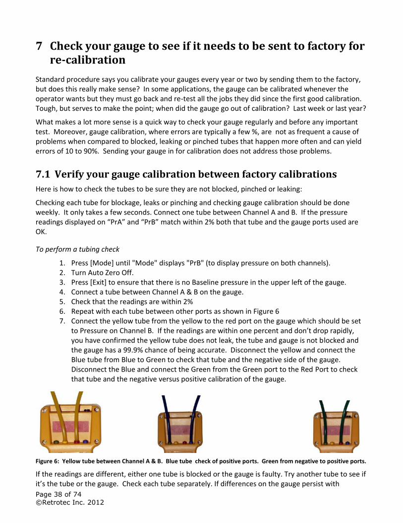
Page 38 of 74
©Retrotec Inc. 2012
7 Check your gauge to see if it needs to be sent to factory for re-calibration
Standard procedure says you calibrate your gauges every year or two by sending them to the factory, but does this really make sense? In some applications, the gauge can be calibrated whenever the operator wants but they must go back and re-test all the jobs they did since the first good calibration. Tough, but serves to make the point; when did the gauge go out of calibration? Last week or last year?
What makes a lot more sense is a quick way to check your gauge regularly and before any important test. Moreover, gauge calibration, where errors are typically a few %, are not as frequent a cause of problems when compared to blocked, leaking or pinched tubes that happen more often and can yield errors of 10 to 90%. Sending your gauge in for calibration does not address those problems.
7.1 Verify your gauge calibration between factory calibrations
Here is how to check the tubes to be sure they are not blocked, pinched or leaking:
Checking each tube for blockage, leaks or pinching and checking gauge calibration should be done weekly. It only takes a few seconds. Connect one tube between Channel A and B. If the pressure readings displayed on “PrA” and “PrB” match within 2% both that tube and the gauge ports used are OK.
To perform a tubing check
1. Press [Mode] until "Mode" displays "PrB" (to display pressure on both channels). 2. Turn Auto Zero Off. 3. Press [Exit] to ensure that there is no Baseline pressure in the upper left of the gauge. 4. Connect a tube between Channel A & B on the gauge. 5. Check that the readings are within 2% 6. Repeat with each tube between other ports as shown in Figure 6 7. Connect the yellow tube from the yellow to the red port on the gauge which should be set
to Pressure on Channel B. If the readings are within one percent and don’t drop rapidly, you have confirmed the yellow tube does not leak, the tube and gauge is not blocked and the gauge has a 99.9% chance of being accurate. Disconnect the yellow and connect the Blue tube from Blue to Green to check that tube and the negative side of the gauge. Disconnect the Blue and connect the Green from the Green port to the Red Port to check that tube and the negative versus positive calibration of the gauge.
Figure 6: Yellow tube between Channel A & B. Blue tube check of positive ports. Green from negative to positive ports.
If the readings are different, either one tube is blocked or the gauge is faulty. Try another tube to see if it’s the tube or the gauge. Check each tube separately. If differences on the gauge persist with
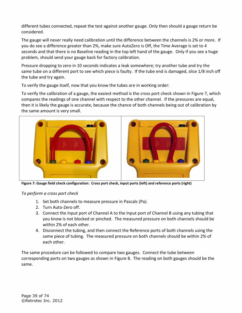
Page 39 of 74
©Retrotec Inc. 2012
different tubes connected, repeat the test against another gauge. Only then should a gauge return be considered.
The gauge will never really need calibration until the difference between the channels is 2% or more. If you do see a difference greater than 2%, make sure AutoZero is Off, the Time Average is set to 4 seconds and that there is no Baseline reading in the top left hand of the gauge. Only if you see a huge problem, should send your gauge back for factory calibration.
Pressure dropping to zero in 10 seconds indicates a leak somewhere; try another tube and try the same tube on a different port to see which piece is faulty. If the tube end is damaged, slice 1/8 inch off the tube and try again.
To verify the gauge itself, now that you know the tubes are in working order:
To verify the calibration of a gauge, the easiest method is the cross port check shown in Figure 7, which compares the readings of one channel with respect to the other channel. If the pressures are equal, then it is likely the gauge is accurate, because the chance of both channels being out of calibration by the same amount is very small.
Figure 7: Gauge field check configuration: Cross port check, input ports (left) and reference ports (right)
To perform a cross port check
1. Set both channels to measure pressure in Pascals (Pa). 2. Turn Auto-Zero off. 3. Connect the Input port of Channel A to the Input port of Channel B using any tubing that
you know is not blocked or pinched. The measured pressure on both channels should be within 2% of each other.
4. Disconnect the tubing, and then connect the Reference ports of both channels using the same piece of tubing. The measured pressure on both channels should be within 2% of each other.
The same procedure can be followed to compare two gauges. Connect the tube between corresponding ports on two gauges as shown in Figure 8. The reading on both gauges should be the same.
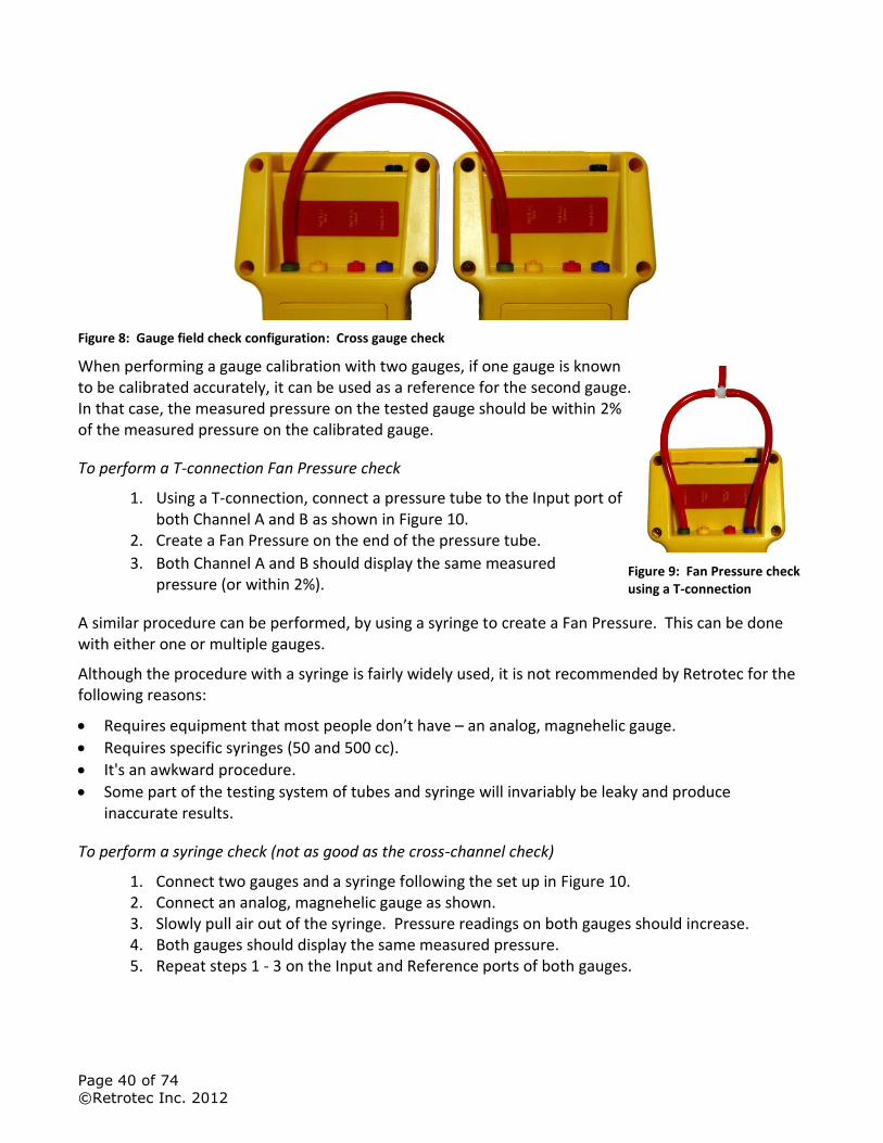
Page 40 of 74
©Retrotec Inc. 2012
Figure 8: Gauge field check configuration: Cross gauge check
When performing a gauge calibration with two gauges, if one gauge is known to be calibrated accurately, it can be used as a reference for the second gauge. In that case, the measured pressure on the tested gauge should be within 2% of the measured pressure on the calibrated gauge.
To perform a T-connection Fan Pressure check
1. Using a T-connection, connect a pressure tube to the Input port of both Channel A and B as shown in Figure 10.
2. Create a Fan Pressure on the end of the pressure tube.
3. Both Channel A and B should display the same measured pressure (or within 2%).
A similar procedure can be performed, by using a syringe to create a Fan Pressure. This can be done with either one or multiple gauges.
Although the procedure with a syringe is fairly widely used, it is not recommended by Retrotec for the following reasons:
Requires equipment that most people don’t have – an analog, magnehelic gauge.
Requires specific syringes (50 and 500 cc).
It's an awkward procedure.
Some part of the testing system of tubes and syringe will invariably be leaky and produce inaccurate results.
To perform a syringe check (not as good as the cross-channel check)
1. Connect two gauges and a syringe following the set up in Figure 10. 2. Connect an analog, magnehelic gauge as shown. 3. Slowly pull air out of the syringe. Pressure readings on both gauges should increase. 4. Both gauges should display the same measured pressure. 5. Repeat steps 1 - 3 on the Input and Reference ports of both gauges.
Figure 9: Fan Pressure check using a T-connection
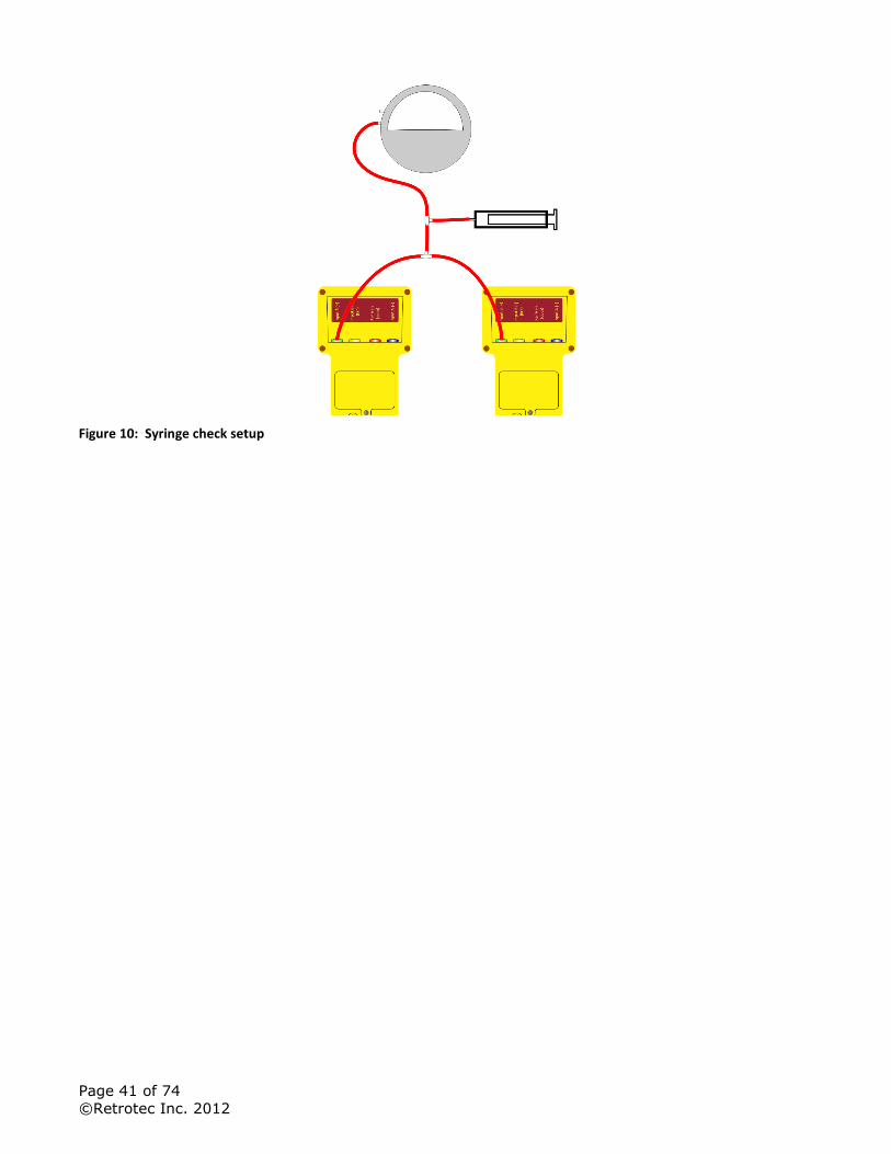
Page 41 of 74
©Retrotec Inc. 2012
Figure 10: Syringe check setup
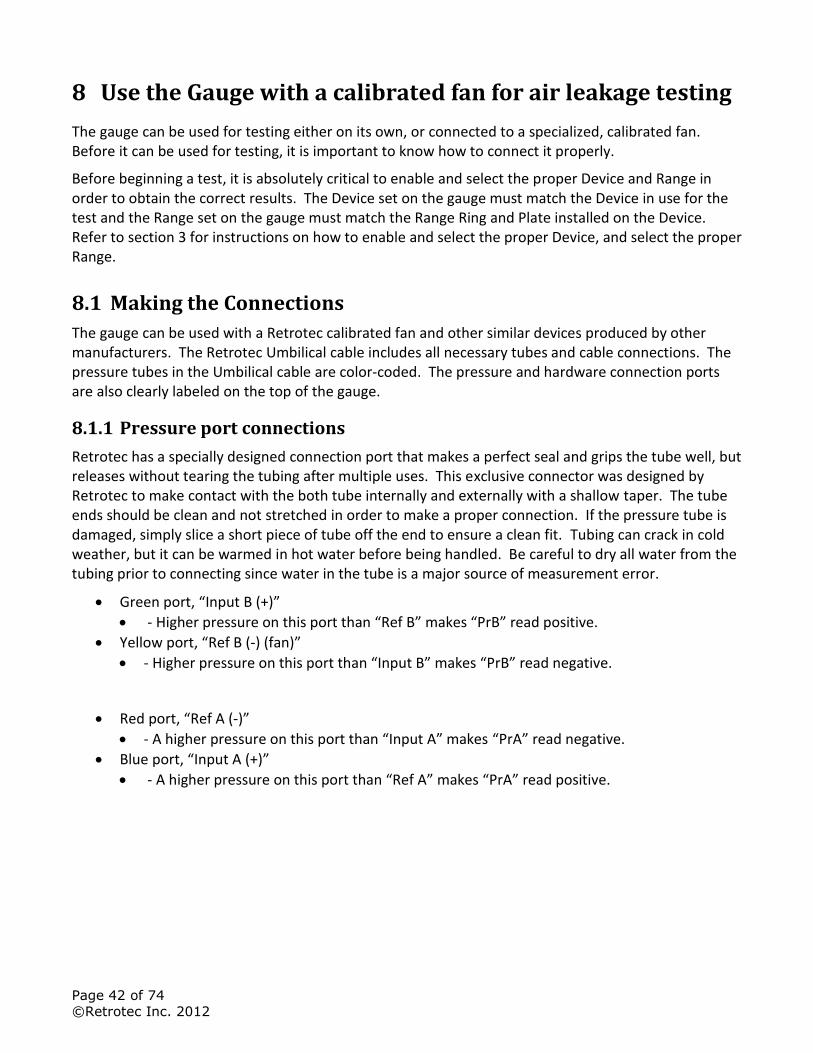
Page 42 of 74
©Retrotec Inc. 2012
8 Use the Gauge with a calibrated fan for air leakage testing
The gauge can be used for testing either on its own, or connected to a specialized, calibrated fan. Before it can be used for testing, it is important to know how to connect it properly.
Before beginning a test, it is absolutely critical to enable and select the proper Device and Range in order to obtain the correct results. The Device set on the gauge must match the Device in use for the test and the Range set on the gauge must match the Range Ring and Plate installed on the Device. Refer to section 3 for instructions on how to enable and select the proper Device, and select the proper Range.
8.1 Making the Connections
The gauge can be used with a Retrotec calibrated fan and other similar devices produced by other manufacturers. The Retrotec Umbilical cable includes all necessary tubes and cable connections. The pressure tubes in the Umbilical cable are color-coded. The pressure and hardware connection ports are also clearly labeled on the top of the gauge.
8.1.1 Pressure port connections
Retrotec has a specially designed connection port that makes a perfect seal and grips the tube well, but releases without tearing the tubing after multiple uses. This exclusive connector was designed by Retrotec to make contact with the both tube internally and externally with a shallow taper. The tube ends should be clean and not stretched in order to make a proper connection. If the pressure tube is damaged, simply slice a short piece of tube off the end to ensure a clean fit. Tubing can crack in cold weather, but it can be warmed in hot water before being handled. Be careful to dry all water from the tubing prior to connecting since water in the tube is a major source of measurement error.
Green port, “Input B (+)”
- Higher pressure on this port than “Ref B” makes “PrB” read positive.
Yellow port, “Ref B (-) (fan)”
- Higher pressure on this port than “Input B” makes “PrB” read negative.
Red port, “Ref A (-)”
- A higher pressure on this port than “Input A” makes “PrA” read negative.
Blue port, “Input A (+)”
- A higher pressure on this port than “Ref A” makes “PrA” read positive.
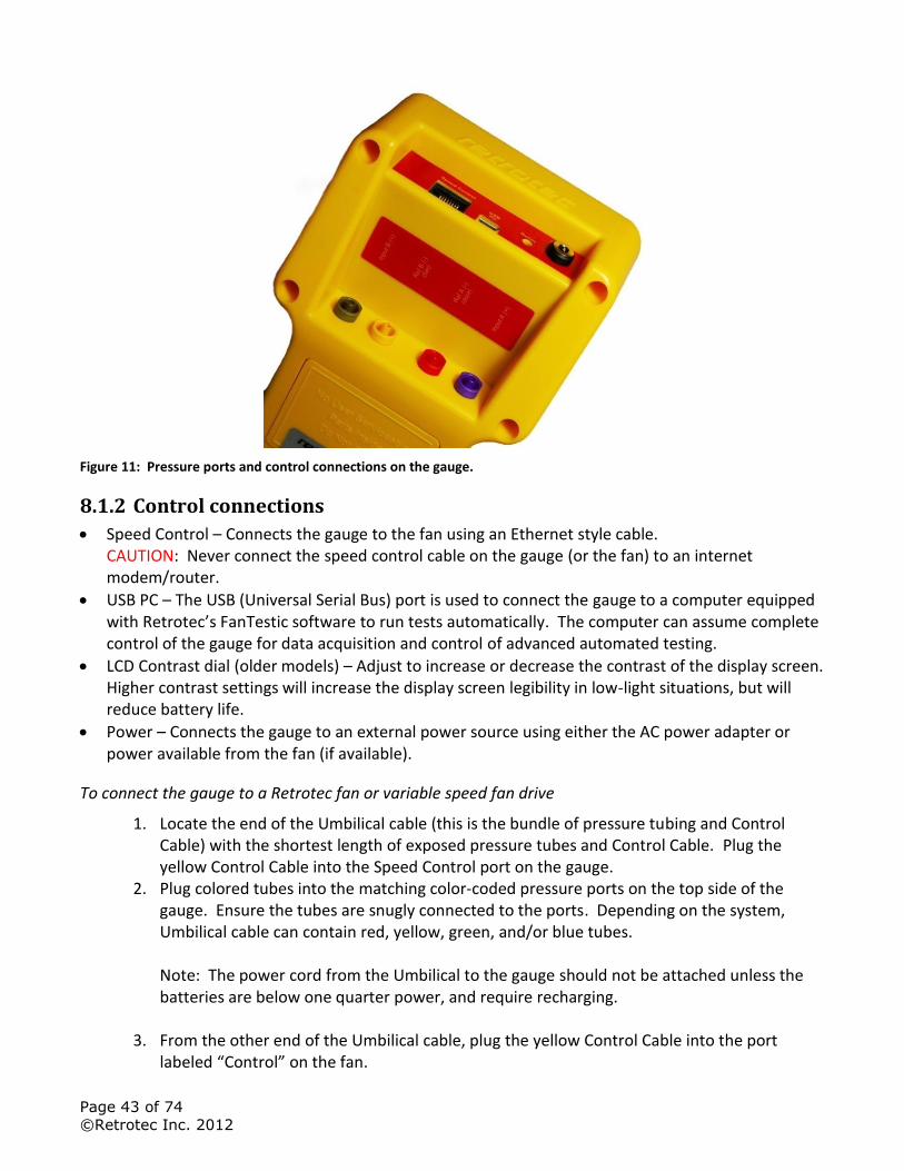
Page 43 of 74
©Retrotec Inc. 2012
Figure 11: Pressure ports and control connections on the gauge.
8.1.2 Control connections
Speed Control – Connects the gauge to the fan using an Ethernet style cable. CAUTION: Never connect the speed control cable on the gauge (or the fan) to an internet modem/router.
USB PC – The USB (Universal Serial Bus) port is used to connect the gauge to a computer equipped with Retrotec’s FanTestic software to run tests automatically. The computer can assume complete control of the gauge for data acquisition and control of advanced automated testing.
LCD Contrast dial (older models) – Adjust to increase or decrease the contrast of the display screen. Higher contrast settings will increase the display screen legibility in low-light situations, but will reduce battery life.
Power – Connects the gauge to an external power source using either the AC power adapter or power available from the fan (if available).
To connect the gauge to a Retrotec fan or variable speed fan drive
1. Locate the end of the Umbilical cable (this is the bundle of pressure tubing and Control Cable) with the shortest length of exposed pressure tubes and Control Cable. Plug the yellow Control Cable into the Speed Control port on the gauge.
2. Plug colored tubes into the matching color-coded pressure ports on the top side of the gauge. Ensure the tubes are snugly connected to the ports. Depending on the system, Umbilical cable can contain red, yellow, green, and/or blue tubes. Note: The power cord from the Umbilical to the gauge should not be attached unless the batteries are below one quarter power, and require recharging.
3. From the other end of the Umbilical cable, plug the yellow Control Cable into the port labeled “Control” on the fan.
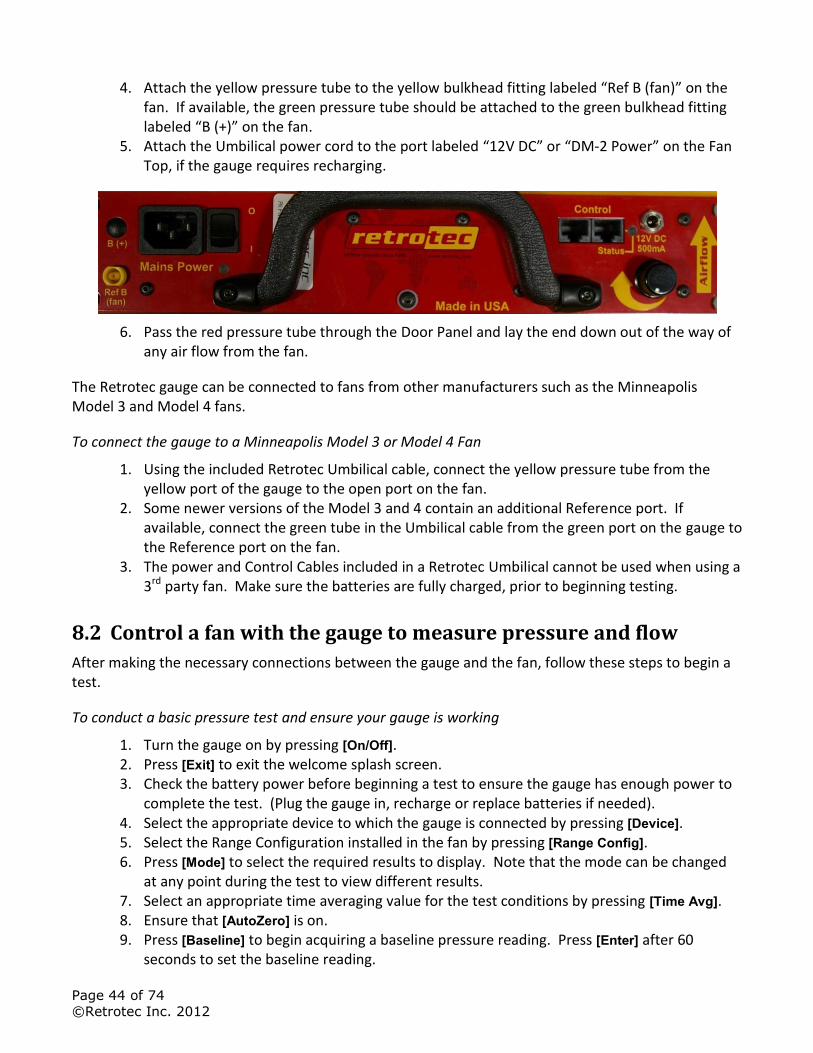
Page 44 of 74
©Retrotec Inc. 2012
4. Attach the yellow pressure tube to the yellow bulkhead fitting labeled “Ref B (fan)” on the fan. If available, the green pressure tube should be attached to the green bulkhead fitting labeled “B (+)” on the fan.
5. Attach the Umbilical power cord to the port labeled “12V DC” or “DM-2 Power” on the Fan Top, if the gauge requires recharging.
6. Pass the red pressure tube through the Door Panel and lay the end down out of the way of any air flow from the fan.
The Retrotec gauge can be connected to fans from other manufacturers such as the Minneapolis Model 3 and Model 4 fans.
To connect the gauge to a Minneapolis Model 3 or Model 4 Fan
1. Using the included Retrotec Umbilical cable, connect the yellow pressure tube from the yellow port of the gauge to the open port on the fan.
2. Some newer versions of the Model 3 and 4 contain an additional Reference port. If available, connect the green tube in the Umbilical cable from the green port on the gauge to the Reference port on the fan.
3. The power and Control Cables included in a Retrotec Umbilical cannot be used when using a 3rd party fan. Make sure the batteries are fully charged, prior to beginning testing.
8.2 Control a fan with the gauge to measure pressure and flow
After making the necessary connections between the gauge and the fan, follow these steps to begin a test.
To conduct a basic pressure test and ensure your gauge is working
1. Turn the gauge on by pressing [On/Off]. 2. Press [Exit] to exit the welcome splash screen. 3. Check the battery power before beginning a test to ensure the gauge has enough power to
complete the test. (Plug the gauge in, recharge or replace batteries if needed). 4. Select the appropriate device to which the gauge is connected by pressing [Device]. 5. Select the Range Configuration installed in the fan by pressing [Range Config]. 6. Press [Mode] to select the required results to display. Note that the mode can be changed
at any point during the test to view different results. 7. Select an appropriate time averaging value for the test conditions by pressing [Time Avg]. 8. Ensure that [AutoZero] is on. 9. Press [Baseline] to begin acquiring a baseline pressure reading. Press [Enter] after 60
seconds to set the baseline reading.
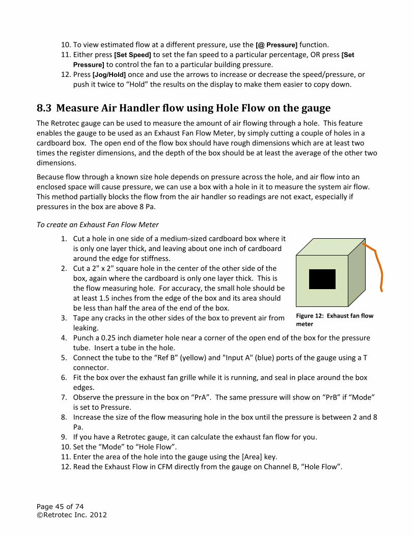
Page 45 of 74
©Retrotec Inc. 2012
10. To view estimated flow at a different pressure, use the [@ Pressure] function. 11. Either press [Set Speed] to set the fan speed to a particular percentage, OR press [Set
Pressure] to control the fan to a particular building pressure. 12. Press [Jog/Hold] once and use the arrows to increase or decrease the speed/pressure, or
push it twice to “Hold” the results on the display to make them easier to copy down.
8.3 Measure Air Handler flow using Hole Flow on the gauge
The Retrotec gauge can be used to measure the amount of air flowing through a hole. This feature enables the gauge to be used as an Exhaust Fan Flow Meter, by simply cutting a couple of holes in a cardboard box. The open end of the flow box should have rough dimensions which are at least two times the register dimensions, and the depth of the box should be at least the average of the other two dimensions.
Because flow through a known size hole depends on pressure across the hole, and air flow into an enclosed space will cause pressure, we can use a box with a hole in it to measure the system air flow. This method partially blocks the flow from the air handler so readings are not exact, especially if pressures in the box are above 8 Pa.
To create an Exhaust Fan Flow Meter
1. Cut a hole in one side of a medium-sized cardboard box where it is only one layer thick, and leaving about one inch of cardboard around the edge for stiffness.
2. Cut a 2" x 2" square hole in the center of the other side of the box, again where the cardboard is only one layer thick. This is the flow measuring hole. For accuracy, the small hole should be at least 1.5 inches from the edge of the box and its area should be less than half the area of the end of the box.
3. Tape any cracks in the other sides of the box to prevent air from leaking.
4. Punch a 0.25 inch diameter hole near a corner of the open end of the box for the pressure tube. Insert a tube in the hole.
5. Connect the tube to the “Ref B” (yellow) and "Input A" (blue) ports of the gauge using a T connector.
6. Fit the box over the exhaust fan grille while it is running, and seal in place around the box edges.
7. Observe the pressure in the box on “PrA”. The same pressure will show on “PrB” if “Mode” is set to Pressure.
8. Increase the size of the flow measuring hole in the box until the pressure is between 2 and 8 Pa.
9. If you have a Retrotec gauge, it can calculate the exhaust fan flow for you. 10. Set the “Mode” to “Hole Flow”. 11. Enter the area of the hole into the gauge using the [Area] key. 12. Read the Exhaust Flow in CFM directly from the gauge on Channel B, “Hole Flow”.
Figure 12: Exhaust fan flow meter

Page 46 of 74
©Retrotec Inc. 2012
Tip: Box pressure of 8 Pa or less is recommended because higher pressures will decrease the exhaust fan flow rate. Box pressures below 3 Pa are less accurate because small fluctuations in pressure will affect the flow a lot. Try the same fan with different holes to see the different results.
Page 47 of 74
©Retrotec Inc. 2012
9 Troubleshooting
After getting a clear understanding of what pressure is and how it's measured, knowing the common causes of erroneous readings will increase your confidence in the results. It is often assumed the gauge must be regularly calibrated in order to get accurate readings, but this thought obscures the fact that most gauge problems do not result from incorrect calibrations. The following list provides approximate percent probabilities based on our experience for certain types of gauge problems. Notice that gauge calibration is one of the smallest, and even that can usually be eliminated by following the gauge check procedures in this manual.
Table 9: Causes of common problems
Problem caused by Error frequency Error range Comments
Tubing is crimped shut 5% 25 to 90% Usually noticeable because gauge does not move, but the blockage may be partial, which could cause an erroneous result.
Water in tubing 10% 75-90% Possible only in wet areas. If gauges sent in to be repaired or calibrated, the water evaporates and the user never discovers the cause.
Improper Device selected 2% 20 to 90% Not common because the wrong Range Configurations will appear on the gauge.
Improper Flow Range selected 5 to 25% 50% Very common unless gauges checked before and after tests to ensure the right Flow Range.
Extrapolation pressure set incorrectly
10% 25% If the gauge shows a different extrapolation pressure [@ Pressure] then the results will be extrapolated to the wrong pressure
Improper use of reference tube for pressurization
5% 25% Pressurization is seldom used, but if the technician is improperly trained, they may not set the equipment up properly for this test.
Time averaging set too high or too low
25% 5 to 10% If the gauge is fluctuating too much it will be difficult to read. If the time averaging is too high, the pressure may have changed but that change is not reflected in the reading.
Wind 25% 10% These errors can be eliminated by long-term averaging or by multiple pressure pickups.
Out of calibration 5% 1-50% Gauges can go out of calibration in a week or may take 10 years. It is impossible to tell unless the readings seem unreasonable.
Out of calibration with regular checks
0.5% 1-2% Regular gauge checks can eliminate most of the calibration problems, by identifying large errors immediately, and before erroneous test results can be taken. It is unlikely that errors in excess of 2% would occur if the gauges checked before each use.
Proper training can eliminate almost all of the above errors.
9.1 Check if moving tubes are causing fluctuating pressure
If the measured values on Channel A or B are fluctuating back and forth, in a way that doesn't correspond with any of the current testing conditions, it's possible that the pressure tube is moving. A moving tube can cause a significant error. For instance, a tube that is attached both to the gauge and
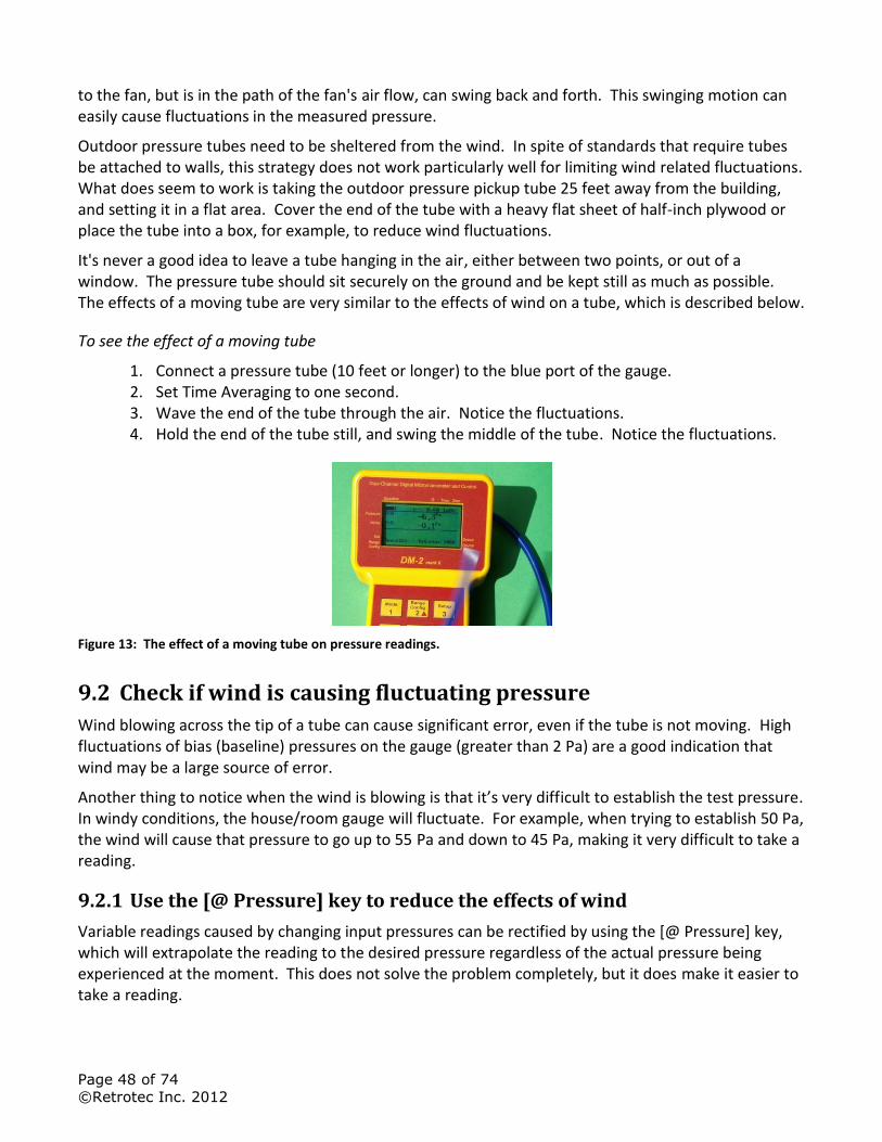
Page 48 of 74
©Retrotec Inc. 2012
to the fan, but is in the path of the fan's air flow, can swing back and forth. This swinging motion can easily cause fluctuations in the measured pressure.
Outdoor pressure tubes need to be sheltered from the wind. In spite of standards that require tubes be attached to walls, this strategy does not work particularly well for limiting wind related fluctuations. What does seem to work is taking the outdoor pressure pickup tube 25 feet away from the building, and setting it in a flat area. Cover the end of the tube with a heavy flat sheet of half-inch plywood or place the tube into a box, for example, to reduce wind fluctuations.
It's never a good idea to leave a tube hanging in the air, either between two points, or out of a window. The pressure tube should sit securely on the ground and be kept still as much as possible. The effects of a moving tube are very similar to the effects of wind on a tube, which is described below.
To see the effect of a moving tube
1. Connect a pressure tube (10 feet or longer) to the blue port of the gauge. 2. Set Time Averaging to one second. 3. Wave the end of the tube through the air. Notice the fluctuations. 4. Hold the end of the tube still, and swing the middle of the tube. Notice the fluctuations.
Figure 13: The effect of a moving tube on pressure readings.
9.2 Check if wind is causing fluctuating pressure
Wind blowing across the tip of a tube can cause significant error, even if the tube is not moving. High fluctuations of bias (baseline) pressures on the gauge (greater than 2 Pa) are a good indication that wind may be a large source of error.
Another thing to notice when the wind is blowing is that it’s very difficult to establish the test pressure. In windy conditions, the house/room gauge will fluctuate. For example, when trying to establish 50 Pa, the wind will cause that pressure to go up to 55 Pa and down to 45 Pa, making it very difficult to take a reading.
9.2.1 Use the [@ Pressure] key to reduce the effects of wind
Variable readings caused by changing input pressures can be rectified by using the [@ Pressure] key, which will extrapolate the reading to the desired pressure regardless of the actual pressure being experienced at the moment. This does not solve the problem completely, but it does make it easier to take a reading.
Page 49 of 74
©Retrotec Inc. 2012
9.2.2 Use Time Averaging feature to reduce the effects of wind
Variable readings caused by changing input pressures can be rectified by increasing the Time Averaging to 20 seconds or more. Quadrupling the Time Averaging typically halves the pressure variation due to the effects of wind. Be aware that if the fan is increasing or decreasing in speed, it will take 20 seconds at least for the gauge to register its reading. For example, if during the initial 10 seconds there was no building pressure whatsoever, and during the second 10 seconds there was 50 Pa, then the gauge will average that to 25 Pa. The rule of thumb here is to wait for at least double the time average period before a reading is taken.
[Time Avg] exercise to practice reducing the effects of wind
1. Use a fan to create an air stream. 1. Set Time Averaging to “1 s”. 2. Place a tube, connected to the positive port, in the path of the air stream. 3. The gauge will display a pressure that fluctuates. Adjust the "wind" speed until the gauge is
reading between 2 and 5 Pa. 4. Adjust Time Averaging to 20 seconds. 5. Notice that after 20 seconds, the gauge reading fluctuates significantly less.
9.2.3 Use Baseline feature to reduce the effects of a constant wind
The [Baseline] feature can be used to minimize the effects of Bias Pressures, including that caused by wind if the wind is relatively constant. This will reduce remove the bias caused by constant wind from the measurements but will not help with the fluctuating nature of wind which is the biggest issue.
[Baseline] exercise to practice minimizing the effects of wind
1. Use a fan to create an air stream that causes between 2 and 5 Pa pressure. 2. Set Time Averaging to one second. 3. Place a tube, connected to the positive port, in the path of the air stream. 4. Establish a Baseline pressure. 5. Notice that once a Baseline pressure is taken, the measured pressure drops closer to zero,
negating the effects of the wind on the actual measured pressure. 6. Stop the fan. 7. Notice now that the measure pressure is negative, even though no pressure is being
received by the gauge. With the Baseline feature still active, the gauge is compensating for a pressure that does not exist. Clear the baseline reading to eliminate this error.
9.2.4 In extreme cases you can use a Wind Damping Kit designed to reduce wind-related fluctuations
In extreme cases, wind damping kits split the main pressure pickup point into either two or four directions, which will average the fluctuation across the building. Recent experience has shown that longer time averaging on a digital gauge is almost as effective as the four tube wind damping kit. When the time taken to set up the kit is taken into account, increasing the time averaging will actually save time.
A wind damping system can be used to average out the wind, and get a more stable pressure reading. In addition to a number of suggestions for obtaining better performance from a single tube system,
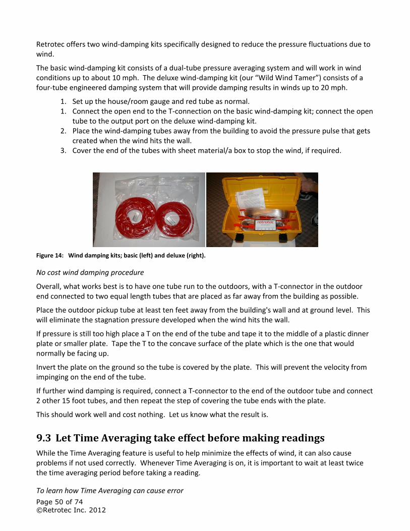
Page 50 of 74
©Retrotec Inc. 2012
Retrotec offers two wind-damping kits specifically designed to reduce the pressure fluctuations due to wind.
The basic wind-damping kit consists of a dual-tube pressure averaging system and will work in wind conditions up to about 10 mph. The deluxe wind-damping kit (our “Wild Wind Tamer”) consists of a four-tube engineered damping system that will provide damping results in winds up to 20 mph.
1. Set up the house/room gauge and red tube as normal. 1. Connect the open end to the T-connection on the basic wind-damping kit; connect the open
tube to the output port on the deluxe wind-damping kit. 2. Place the wind-damping tubes away from the building to avoid the pressure pulse that gets
created when the wind hits the wall. 3. Cover the end of the tubes with sheet material/a box to stop the wind, if required.
Figure 14: Wind damping kits; basic (left) and deluxe (right).
No cost wind damping procedure
Overall, what works best is to have one tube run to the outdoors, with a T-connector in the outdoor end connected to two equal length tubes that are placed as far away from the building as possible.
Place the outdoor pickup tube at least ten feet away from the building's wall and at ground level. This will eliminate the stagnation pressure developed when the wind hits the wall.
If pressure is still too high place a T on the end of the tube and tape it to the middle of a plastic dinner plate or smaller plate. Tape the T to the concave surface of the plate which is the one that would normally be facing up.
Invert the plate on the ground so the tube is covered by the plate. This will prevent the velocity from impinging on the end of the tube.
If further wind damping is required, connect a T-connector to the end of the outdoor tube and connect 2 other 15 foot tubes, and then repeat the step of covering the tube ends with the plate.
This should work well and cost nothing. Let us know what the result is.
9.3 Let Time Averaging take effect before making readings
While the Time Averaging feature is useful to help minimize the effects of wind, it can also cause problems if not used correctly. Whenever Time Averaging is on, it is important to wait at least twice the time averaging period before taking a reading.
To learn how Time Averaging can cause error
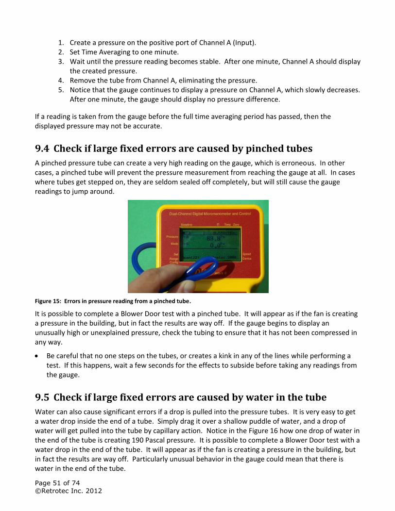
Page 51 of 74
©Retrotec Inc. 2012
1. Create a pressure on the positive port of Channel A (Input). 2. Set Time Averaging to one minute. 3. Wait until the pressure reading becomes stable. After one minute, Channel A should display
the created pressure. 4. Remove the tube from Channel A, eliminating the pressure. 5. Notice that the gauge continues to display a pressure on Channel A, which slowly decreases.
After one minute, the gauge should display no pressure difference.
If a reading is taken from the gauge before the full time averaging period has passed, then the displayed pressure may not be accurate.
9.4 Check if large fixed errors are caused by pinched tubes
A pinched pressure tube can create a very high reading on the gauge, which is erroneous. In other cases, a pinched tube will prevent the pressure measurement from reaching the gauge at all. In cases where tubes get stepped on, they are seldom sealed off completely, but will still cause the gauge readings to jump around.
Figure 15: Errors in pressure reading from a pinched tube.
It is possible to complete a Blower Door test with a pinched tube. It will appear as if the fan is creating a pressure in the building, but in fact the results are way off. If the gauge begins to display an unusually high or unexplained pressure, check the tubing to ensure that it has not been compressed in any way.
Be careful that no one steps on the tubes, or creates a kink in any of the lines while performing a test. If this happens, wait a few seconds for the effects to subside before taking any readings from the gauge.
9.5 Check if large fixed errors are caused by water in the tube
Water can also cause significant errors if a drop is pulled into the pressure tubes. It is very easy to get a water drop inside the end of a tube. Simply drag it over a shallow puddle of water, and a drop of water will get pulled into the tube by capillary action. Notice in the Figure 16 how one drop of water in the end of the tube is creating 190 Pascal pressure. It is possible to complete a Blower Door test with a water drop in the end of the tube. It will appear as if the fan is creating a pressure in the building, but in fact the results are way off. Particularly unusual behavior in the gauge could mean that there is water in the end of the tube.
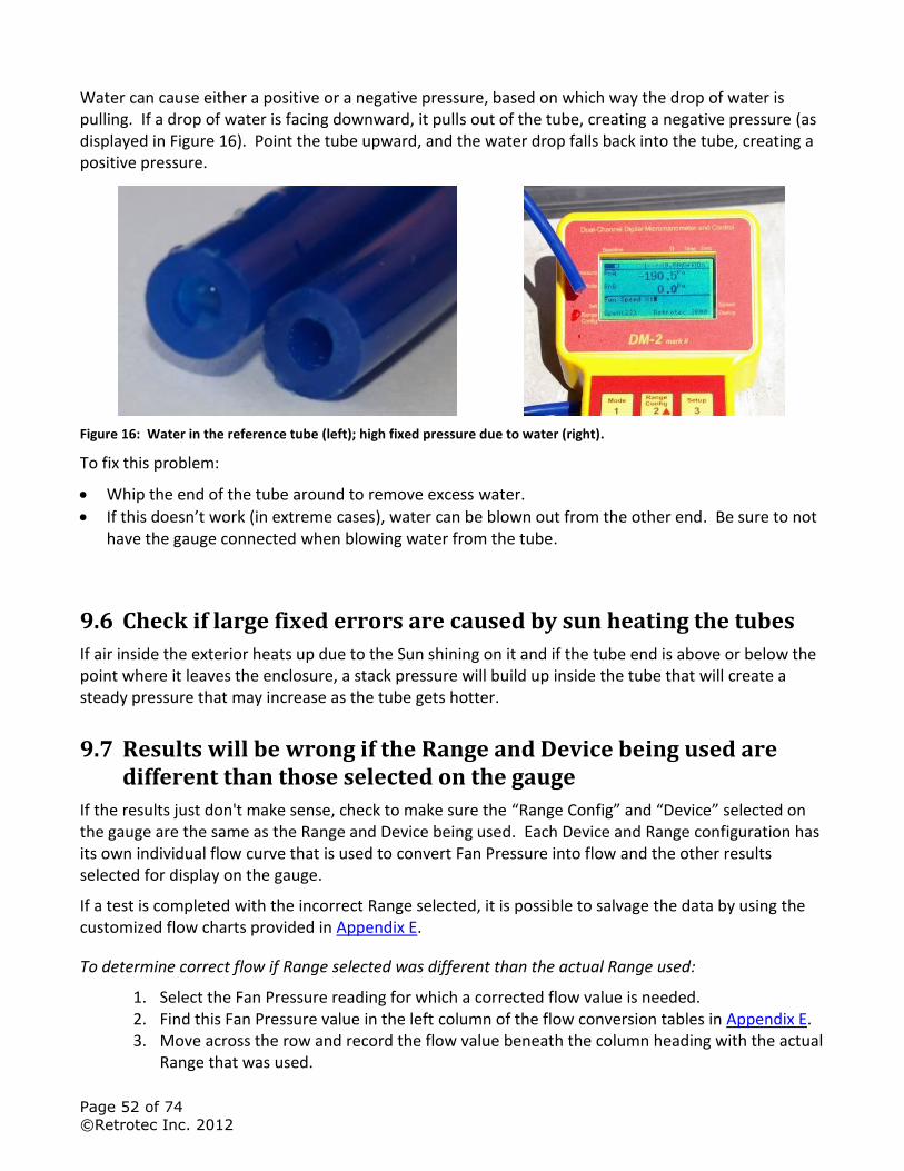
Page 52 of 74
©Retrotec Inc. 2012
Water can cause either a positive or a negative pressure, based on which way the drop of water is pulling. If a drop of water is facing downward, it pulls out of the tube, creating a negative pressure (as displayed in Figure 16). Point the tube upward, and the water drop falls back into the tube, creating a positive pressure.
Figure 16: Water in the reference tube (left); high fixed pressure due to water (right).
To fix this problem:
Whip the end of the tube around to remove excess water.
If this doesn’t work (in extreme cases), water can be blown out from the other end. Be sure to not have the gauge connected when blowing water from the tube.
9.6 Check if large fixed errors are caused by sun heating the tubes
If air inside the exterior heats up due to the Sun shining on it and if the tube end is above or below the point where it leaves the enclosure, a stack pressure will build up inside the tube that will create a steady pressure that may increase as the tube gets hotter.
9.7 Results will be wrong if the Range and Device being used are different than those selected on the gauge
If the results just don't make sense, check to make sure the “Range Config” and “Device” selected on the gauge are the same as the Range and Device being used. Each Device and Range configuration has its own individual flow curve that is used to convert Fan Pressure into flow and the other results selected for display on the gauge.
If a test is completed with the incorrect Range selected, it is possible to salvage the data by using the customized flow charts provided in Appendix E.
To determine correct flow if Range selected was different than the actual Range used:
1. Select the Fan Pressure reading for which a corrected flow value is needed. 2. Find this Fan Pressure value in the left column of the flow conversion tables in Appendix E. 3. Move across the row and record the flow value beneath the column heading with the actual
Range that was used.
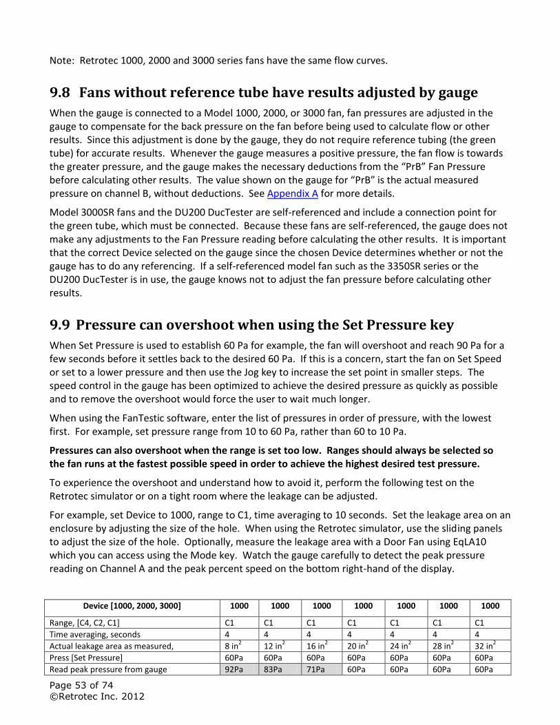
Page 53 of 74
©Retrotec Inc. 2012
Note: Retrotec 1000, 2000 and 3000 series fans have the same flow curves.
9.8 Fans without reference tube have results adjusted by gauge
When the gauge is connected to a Model 1000, 2000, or 3000 fan, fan pressures are adjusted in the gauge to compensate for the back pressure on the fan before being used to calculate flow or other results. Since this adjustment is done by the gauge, they do not require reference tubing (the green tube) for accurate results. Whenever the gauge measures a positive pressure, the fan flow is towards the greater pressure, and the gauge makes the necessary deductions from the “PrB” Fan Pressure before calculating other results. The value shown on the gauge for “PrB” is the actual measured pressure on channel B, without deductions. See Appendix A for more details.
Model 3000SR fans and the DU200 DucTester are self-referenced and include a connection point for the green tube, which must be connected. Because these fans are self-referenced, the gauge does not make any adjustments to the Fan Pressure reading before calculating the other results. It is important that the correct Device selected on the gauge since the chosen Device determines whether or not the gauge has to do any referencing. If a self-referenced model fan such as the 3350SR series or the DU200 DucTester is in use, the gauge knows not to adjust the fan pressure before calculating other results.
9.9 Pressure can overshoot when using the Set Pressure key
When Set Pressure is used to establish 60 Pa for example, the fan will overshoot and reach 90 Pa for a few seconds before it settles back to the desired 60 Pa. If this is a concern, start the fan on Set Speed or set to a lower pressure and then use the Jog key to increase the set point in smaller steps. The speed control in the gauge has been optimized to achieve the desired pressure as quickly as possible and to remove the overshoot would force the user to wait much longer.
When using the FanTestic software, enter the list of pressures in order of pressure, with the lowest first. For example, set pressure range from 10 to 60 Pa, rather than 60 to 10 Pa.
Pressures can also overshoot when the range is set too low. Ranges should always be selected so the fan runs at the fastest possible speed in order to achieve the highest desired test pressure.
To experience the overshoot and understand how to avoid it, perform the following test on the Retrotec simulator or on a tight room where the leakage can be adjusted.
For example, set Device to 1000, range to C1, time averaging to 10 seconds. Set the leakage area on an enclosure by adjusting the size of the hole. When using the Retrotec simulator, use the sliding panels to adjust the size of the hole. Optionally, measure the leakage area with a Door Fan using EqLA10 which you can access using the Mode key. Watch the gauge carefully to detect the peak pressure reading on Channel A and the peak percent speed on the bottom right-hand of the display.
Device [1000, 2000, 3000] 1000 1000 1000 1000 1000 1000 1000
Range, [C4, C2, C1] C1 C1 C1 C1 C1 C1 C1
Time averaging, seconds 4 4 4 4 4 4 4
Actual leakage area as measured, 8 in2 12 in
2 16 in
2 20 in
2 24 in
2 28 in
2 32 in
2
Press [Set Pressure] 60Pa 60Pa 60Pa 60Pa 60Pa 60Pa 60Pa
Read peak pressure from gauge 92Pa 83Pa 71Pa 60Pa 60Pa 60Pa 60Pa
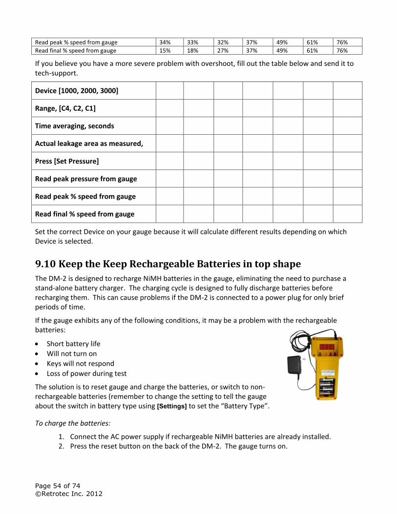
Page 54 of 74
©Retrotec Inc. 2012
Read peak % speed from gauge 34% 33% 32% 37% 49% 61% 76%
Read final % speed from gauge 15% 18% 27% 37% 49% 61% 76%
If you believe you have a more severe problem with overshoot, fill out the table below and send it to tech-support.
Device [1000, 2000, 3000]
Range, [C4, C2, C1]
Time averaging, seconds
Actual leakage area as measured,
Press [Set Pressure]
Read peak pressure from gauge
Read peak % speed from gauge
Read final % speed from gauge
Set the correct Device on your gauge because it will calculate different results depending on which Device is selected.
9.10 Keep the Keep Rechargeable Batteries in top shape
The DM-2 is designed to recharge NiMH batteries in the gauge, eliminating the need to purchase a stand-alone battery charger. The charging cycle is designed to fully discharge batteries before recharging them. This can cause problems if the DM-2 is connected to a power plug for only brief periods of time.
If the gauge exhibits any of the following conditions, it may be a problem with the rechargeable batteries:
Short battery life
Will not turn on
Keys will not respond
Loss of power during test
The solution is to reset gauge and charge the batteries, or switch to non-rechargeable batteries (remember to change the setting to tell the gauge about the switch in battery type using [Settings] to set the “Battery Type”.
To charge the batteries:
1. Connect the AC power supply if rechargeable NiMH batteries are already installed. 2. Press the reset button on the back of the DM-2. The gauge turns on.
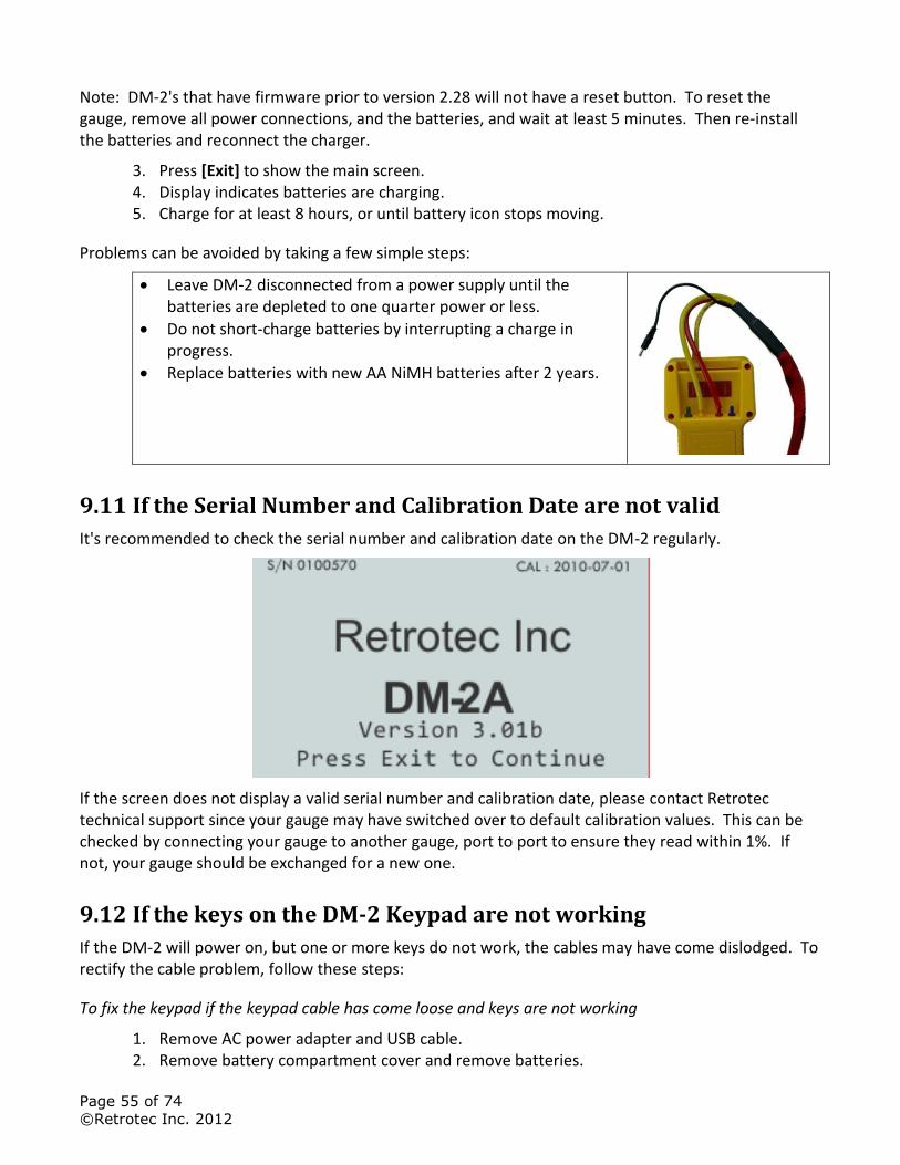
Page 55 of 74
©Retrotec Inc. 2012
Note: DM-2's that have firmware prior to version 2.28 will not have a reset button. To reset the gauge, remove all power connections, and the batteries, and wait at least 5 minutes. Then re-install the batteries and reconnect the charger.
3. Press [Exit] to show the main screen. 4. Display indicates batteries are charging. 5. Charge for at least 8 hours, or until battery icon stops moving.
Problems can be avoided by taking a few simple steps:
Leave DM-2 disconnected from a power supply until the batteries are depleted to one quarter power or less.
Do not short-charge batteries by interrupting a charge in progress.
Replace batteries with new AA NiMH batteries after 2 years.
9.11 If the Serial Number and Calibration Date are not valid
It's recommended to check the serial number and calibration date on the DM-2 regularly.
If the screen does not display a valid serial number and calibration date, please contact Retrotec technical support since your gauge may have switched over to default calibration values. This can be checked by connecting your gauge to another gauge, port to port to ensure they read within 1%. If not, your gauge should be exchanged for a new one.
9.12 If the keys on the DM-2 Keypad are not working
If the DM-2 will power on, but one or more keys do not work, the cables may have come dislodged. To rectify the cable problem, follow these steps:
To fix the keypad if the keypad cable has come loose and keys are not working
1. Remove AC power adapter and USB cable. 2. Remove battery compartment cover and remove batteries.
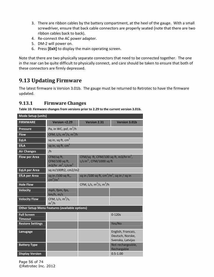
Page 56 of 74
©Retrotec Inc. 2012
3. There are ribbon cables by the battery compartment, at the heel of the gauge. With a small screwdriver, ensure that back cable connectors are properly seated (note that there are two ribbon cables back to back).
4. Re-connect the AC power adapter. 5. DM-2 will power on. 6. Press [Exit] to display the main operating screen.
Note that there are two physically separate connectors that need to be connected together. The one in the rear can be quite difficult to physically connect, and care should be taken to ensure that both of these connectors are firmly depressed.
9.13 Updating Firmware
The latest firmware is Version 3.01b. The gauge must be returned to Retrotec to have the firmware updated.
9.13.1 Firmware Changes Table 10: Firmware changes from versions prior to 2.29 to the current version 3.01b.
Mode Setup (units)
FIRMWARE Version <2.29 Version 2.31 Version 3.01b
Pressure Pa, in WC, psf, m3/h
Flow CFM, L/s, m3/s, m
3/h
EqLA sq in, sq ft, cm2
EfLA sq in, sq ft, cm2
Air Changes /h
Flow per Area CFM/sq ft, CFM/100 sq ft, m3/hr .m
2, L/s
.m
2
CFM/sq ft, CFM/100 sq ft, m3/hr.m
2,
L/s.m
2,, CFM/1000 sq ft
EqLA per Area sq in/100ft2, cm2/m2
EfLA per Area sq in /100 sq ft,, cm
2/m
2
sq in /100 sq ft, cm2/m
2, sq in / sq in
Hole Flow CFM, L/s, m3/s, m
3/h
Velocity mph, fpm, fps, km/h, m/s
Velocity Flow CFM, L/s, m3/s,
m3/h
Other Setup Menu Features (available options)
Full Screen Timeout
0-120s
Restore Settings Yes/No
Lanugage English, Francais, Deutsch, Norske, Svenska, Latvijas
Battery Type Not rechargeable, Rechargable
Display Version 0.5-1.00
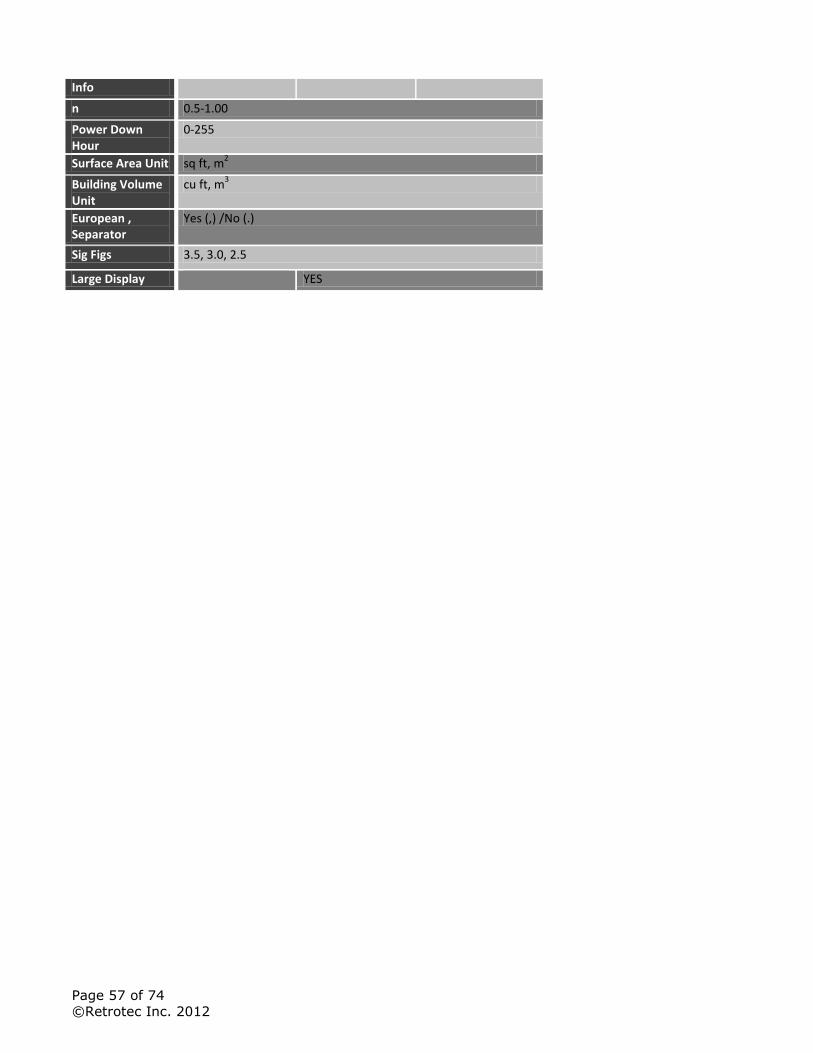
Page 57 of 74
©Retrotec Inc. 2012
Info
n 0.5-1.00
Power Down Hour
0-255
Surface Area Unit sq ft, m2
Building Volume Unit
cu ft, m3
European , Separator
Yes (,) /No (.)
Sig Figs 3.5, 3.0, 2.5
Large Display YES
Page 58 of 74
©Retrotec Inc. 2012
Appendix A: The gauge calculates Flow based on Pressure readings from the fan
The air flow being produced by the calibrated fan is a value that can be calculated based on the pressure developed by the air moving across the inlet side of the fan towards the exhaust. Because the fan is calibrated, there are known values describing the mathematical relationship between the fan pressure, which is measured across the fan inlet, and the resulting air flow through the fan.
The Fan Pressure needed to calculate the fan flow is the difference between the pressure at the pickup and the pressure in the vicinity of the inlet side of the fan. The fan pressure pickup is located inside the fan near the inlet side of the fan. Self-referencing fans have the reference port built in, and it is placed to measure the ambient pressure in the vicinity of the inlet side of the fan. Fan Pressure, FP, is determined by setting the gauge Mode to “PrB” and reading the resulting pressure on the gauge when the room is at the test pressure.
Each fan and range combination has a different flow equation. For each fan and range combination available, the variables needed to calculate flow are listed in the table below.
The form of the flow equation depends on where the pickup for the Fan Pressure connected to the yellow “Ref B” port on the gauge is located with respect to the green “Input B” port of the gauge.
Case 1: Flow Away from Operator
If the flow of the fan is away from the operator holding the gauge, then the gauge and the operator are on the inlet side of the fan. Readings on Channel A in this case will always be negative, measuring the induced pressure in the room.
Since both the fan pressure pickup and the reference for the fan pressure (yellow port on the fan and green port on the gauge) are on the inlet side of the fan, “PrB”, will show the correctly referenced fan pressure and can be used directly as the fan pressure, FP, value in the following flow equation:
( | | ) ( )
Where:
FP is the fan pressure from Channel B displayed as “PrB”
RP is the room pressure from Channel A displayed as “PrA”
Case 2: Flow Toward Operator
If the flow of the fan is toward the operator holding the gauge, then the gauge is on the exhaust side of the fan while the fan pressure pickup is on the opposite (inlet) side. The exhaust side is the side on which the room pressure is being induced by the fan. Readings on Channel A in this case will always be positive, measuring the induced pressure in the room.
Because the gauge which has the green “Input B” port is in the room with the induced pressure, the pressure difference measured on Channel B will include the induced room pressure as well as the actual Fan Pressure across the inlet. “PrB” will thus show a pressure difference that is larger than the actual fan pressure, larger by an amount equal to the induced room pressure being measured on Channel A.
Any time the gauge sees a positive pressure on Channel A, it automatically subtracts the value on Channel A from the value on Channel B before calculating flow and other results. The value displayed
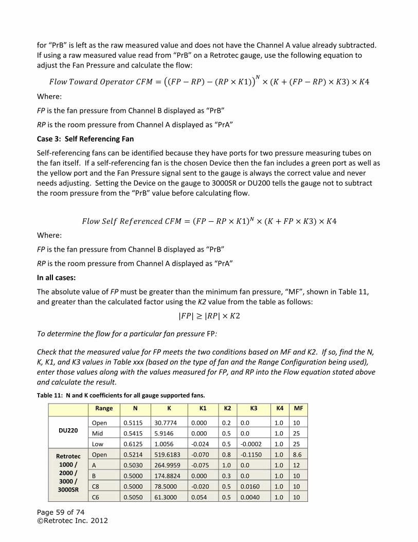
Page 59 of 74
©Retrotec Inc. 2012
for “PrB” is left as the raw measured value and does not have the Channel A value already subtracted. If using a raw measured value read from “PrB” on a Retrotec gauge, use the following equation to adjust the Fan Pressure and calculate the flow:
(( ) ( )) ( ( ) )
Where:
FP is the fan pressure from Channel B displayed as “PrB”
RP is the room pressure from Channel A displayed as “PrA”
Case 3: Self Referencing Fan
Self-referencing fans can be identified because they have ports for two pressure measuring tubes on the fan itself. If a self-referencing fan is the chosen Device then the fan includes a green port as well as the yellow port and the Fan Pressure signal sent to the gauge is always the correct value and never needs adjusting. Setting the Device on the gauge to 3000SR or DU200 tells the gauge not to subtract the room pressure from the “PrB” value before calculating flow.
( ) ( )
Where:
FP is the fan pressure from Channel B displayed as “PrB”
RP is the room pressure from Channel A displayed as “PrA”
In all cases:
The absolute value of FP must be greater than the minimum fan pressure, “MF”, shown in Table 11, and greater than the calculated factor using the K2 value from the table as follows:
| | | |
To determine the flow for a particular fan pressure FP:
Check that the measured value for FP meets the two conditions based on MF and K2. If so, find the N, K, K1, and K3 values in Table xxx (based on the type of fan and the Range Configuration being used), enter those values along with the values measured for FP, and RP into the Flow equation stated above and calculate the result.
Table 11: N and K coefficients for all gauge supported fans.
Range N K K1 K2 K3 K4 MF
DU220 Open 0.5115 30.7774 0.000 0.2 0.0 1.0 10
Mid 0.5415 5.9146 0.000 0.5 0.0 1.0 25
Low 0.6125 1.0056 -0.024 0.5 -0.0002 1.0 25
Retrotec 1000 / 2000 / 3000 / 3000SR
Open 0.5214 519.6183 -0.070 0.8 -0.1150 1.0 8.6
A 0.5030 264.9959 -0.075 1.0 0.0 1.0 12
B 0.5000 174.8824 0.000 0.3 0.0 1.0 10
C8 0.5000 78.5000 -0.020 0.5 0.0160 1.0 10
C6 0.5050 61.3000 0.054 0.5 0.0040 1.0 10
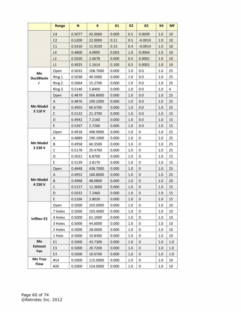
Page 60 of 74
©Retrotec Inc. 2012
Range N K K1 K2 K3 K4 MF
C4 0.5077 42.0000 0.009 0.5 0.0009 1.0 10
C2 0.5200 22.0000 0.11 0.5 -0.0010 1.0 10
C1 0.5410 11.9239 0.13 0.4 -0.0014 1.0 10
L4 0.4800 4.0995 0.003 1.0 0.0004 1.0 10
L2 0.5020 2.0678 0.000 0.5 0.0001 1.0 10
L1 0.4925 1.1614 0.100 0.5 0.0001 1.0 10
Mn DuctBlaste
r
Open 0.5032 108.7000 0.000 1.0 0.0 1.0 25
Ring 1 0.5038 40.5000 0.000 1.0 0.0 1.0 25
Ring 2 0.5064 15.2700 0.000 1.0 0.0 1.0 25
Ring 3 0.5140 5.8400 0.000 1.0 0.0 1.0 4
Mn Model 3 110 V
Open 0.4879 506.8000 0.000 1.0 0.0 1.0 25
A 0.4876 190.1000 0.000 1.0 0.0 1.0 25
B 0.4955 60.6700 0.000 1.0 0.0 1.0 25
C 0.5132 21.3700 0.000 1.0 0.0 1.0 15
D 0.4942 7.2160 0.000 1.0 0.0 1.0 15
E 0.5267 2.7260 0.000 1.0 0.0 1.0 15
Mn Model 3 230 V
Open 0.4918 498.9000 0.000 1.0 0 1.0 25
A 0.4889 190.1000 0.000 1.0 0 1.0 25
B 0.4958 60.3500 0.000 1.0 0 1.0 25
C 0.5178 20.4700 0.000 1.0 0 1.0 25
D 0.5022 6.8700 0.000 1.0 0 1.0 15
E 0.5139 2.8170 0.000 1.0 0 1.0 15
Mn Model 4 230 V
Open 0.4848 438.7000 0.000 1.0 0 1.0 25
A 0.4952 160.8000 0.000 1.0 0 1.0 25
B 0.4968 48.0800 0.000 1.0 0 1.0 20
C 0.5157 11.3600 0.000 1.0 0 1.0 15
D 0.5032 7.2460 0.000 1.0 0 1.0 15
E 0.5166 2.8020 0.000 1.0 0 1.0 15
Infiltec E3
Open 0.5000 103.0000 0.000 1.0 0 1.0 10
7 Holes 0.5000 103.4000 0.000 1.0 0 1.0 10
4 Holes 0.5000 61.1000 0.000 1.0 0 1.0 10
3 Holes 0.5000 44.6000 0.000 1.0 0 1.0 10
2 Holes 0.5000 28.0000 0.000 1.0 0 1.0 10
1 Hole 0.5000 10.8300 0.000 1.0 0 1.0 10
Mn Exhaust
Fan
E1 0.5000 43.7300 0.000 1.0 0 1.0 1.0
E3 0.5000 20.7200 0.000 1.0 0 1.0 1.0
E3 0.5000 10.0700 0.000 1.0 0 1.0 1.0
Mn True Flow
#14 0.5000 115.0000 0.000 1.0 0 1.0 10
#20 0.5000 154.0000 0.000 1.0 0 1.0 10
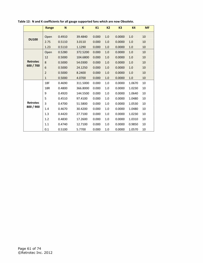
Page 61 of 74
©Retrotec Inc. 2012
Table 12: N and K coefficients for all gauge supported fans which are now Obsolete.
Range N K K1 K2 K3 K4 MF
DU100 Open 0.4910 39.4840 0.000 1.0 0.0000 1.0 10
2.75 0.5110 3.0110 0.000 1.0 0.0000 1.0 10
1.23 0.5110 1.1290 0.000 1.0 0.0000 1.0 10
Retrotec 600 / 700
Open 0.5280 372.5200 0.000 1.0 0.0000 1.0 10
12 0.5000 104.6800 0.000 1.0 0.0000 1.0 10
8 0.5000 54.0300 0.000 1.0 0.0000 1.0 10
6 0.5000 24.1250 0.000 1.0 0.0000 1.0 10
2 0.5000 8.2400 0.000 1.0 0.0000 1.0 10
1 0.5000 4.0700 0.000 1.0 0.0000 1.0 10
Retrotec 800 / 900
18F 0.4690 311.5000 0.000 1.0 0.0000 1.0670 10
18R 0.4800 366.8000 0.000 1.0 0.0000 1.0230 10
9 0.4920 144.5500 0.000 1.0 0.0000 1.0640 10
5 0.4510 97.4100 0.000 1.0 0.0000 1.0480 10
3 0.4700 51.5800 0.000 1.0 0.0000 1.0530 10
1.4 0.4670 30.4200 0.000 1.0 0.0000 1.0480 10
1.3 0.4420 27.7100 0.000 1.0 0.0000 1.0230 10
1.2 0.4830 17.2600 0.000 1.0 0.0000 1.0310 10
1.1 0.4740 12.7100 0.000 1.0 0.0000 0.9850 10
0.1 0.5100 5.7700 0.000 1.0 0.0000 1.0570 10
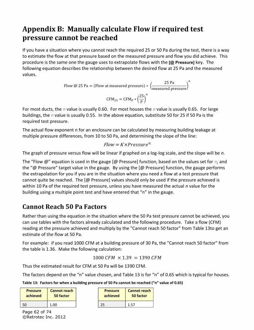
Page 62 of 74
©Retrotec Inc. 2012
Appendix B: Manually calculate Flow if required test pressure cannot be reached
If you have a situation where you cannot reach the required 25 or 50 Pa during the test, there is a way to estimate the flow at that pressure based on the measured pressure and flow you did achieve. This procedure is the same one the gauge uses to extrapolate flows with the [@ Pressure] key. The following equation describes the relationship between the desired flow at 25 Pa and the measured values.
( ) (
)
(
)
For most ducts, the n value is usually 0.60. For most houses the n value is usually 0.65. For large buildings, the n value is usually 0.55. In the above equation, substitute 50 for 25 if 50 Pa is the required test pressure.
The actual flow exponent n for an enclosure can be calculated by measuring building leakage at multiple pressure differences, from 10 to 50 Pa, and determining the slope of the line:
The graph of pressure versus flow will be linear if graphed on a log-log scale, and the slope will be n.
The “Flow @” equation is used in the gauge [@ Pressure] function, based on the values set for n, and the “@ Pressure” target value in the gauge. By using the [@ Pressure] function, the gauge performs the extrapolation for you if you are in the situation where you need a flow at a test pressure that cannot quite be reached. The [@ Pressure] values should only be used if the pressure achieved is within 10 Pa of the required test pressure, unless you have measured the actual n value for the building using a multiple point test and have entered that “n” in the gauge.
Cannot Reach 50 Pa Factors
Rather than using the equation in the situation where the 50 Pa test pressure cannot be achieved, you can use tables with the factors already calculated and the following procedure. Take a flow (CFM) reading at the pressure achieved and multiply by the "Cannot reach 50 factor" from Table 13to get an estimate of the flow at 50 Pa.
For example: if you read 1000 CFM at a building pressure of 30 Pa, the "Cannot reach 50 factor" from the table is 1.36. Make the following calculation:
Thus the estimated result for CFM at 50 Pa will be 1390 CFM.
The factors depend on the “n” value chosen, and Table 13 is for “n” of 0.65 which is typical for houses.
Table 13: Factors for when a building pressure of 50 Pa cannot be reached (“n” value of 0.65)
Pressure achieved
Cannot reach 50 factor
Pressure achieved
Cannot reach 50 factor
50 1.00
25 1.57
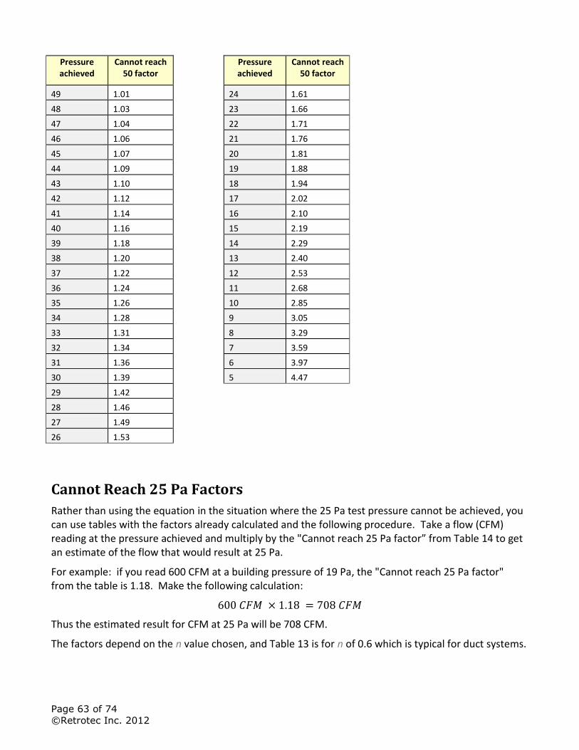
Page 63 of 74
©Retrotec Inc. 2012
Pressure achieved
Cannot reach 50 factor
Pressure achieved
Cannot reach 50 factor
49 1.01
24 1.61
48 1.03
23 1.66
47 1.04
22 1.71
46 1.06
21 1.76
45 1.07
20 1.81
44 1.09
19 1.88
43 1.10
18 1.94
42 1.12
17 2.02
41 1.14
16 2.10
40 1.16
15 2.19
39 1.18
14 2.29
38 1.20
13 2.40
37 1.22
12 2.53
36 1.24
11 2.68
35 1.26
10 2.85
34 1.28
9 3.05
33 1.31
8 3.29
32 1.34
7 3.59
31 1.36
6 3.97
30 1.39
5 4.47
29 1.42 28 1.46 27 1.49 26 1.53
Cannot Reach 25 Pa Factors
Rather than using the equation in the situation where the 25 Pa test pressure cannot be achieved, you can use tables with the factors already calculated and the following procedure. Take a flow (CFM) reading at the pressure achieved and multiply by the "Cannot reach 25 Pa factor” from Table 14 to get an estimate of the flow that would result at 25 Pa.
For example: if you read 600 CFM at a building pressure of 19 Pa, the "Cannot reach 25 Pa factor" from the table is 1.18. Make the following calculation:
Thus the estimated result for CFM at 25 Pa will be 708 CFM.
The factors depend on the n value chosen, and Table 13 is for n of 0.6 which is typical for duct systems.
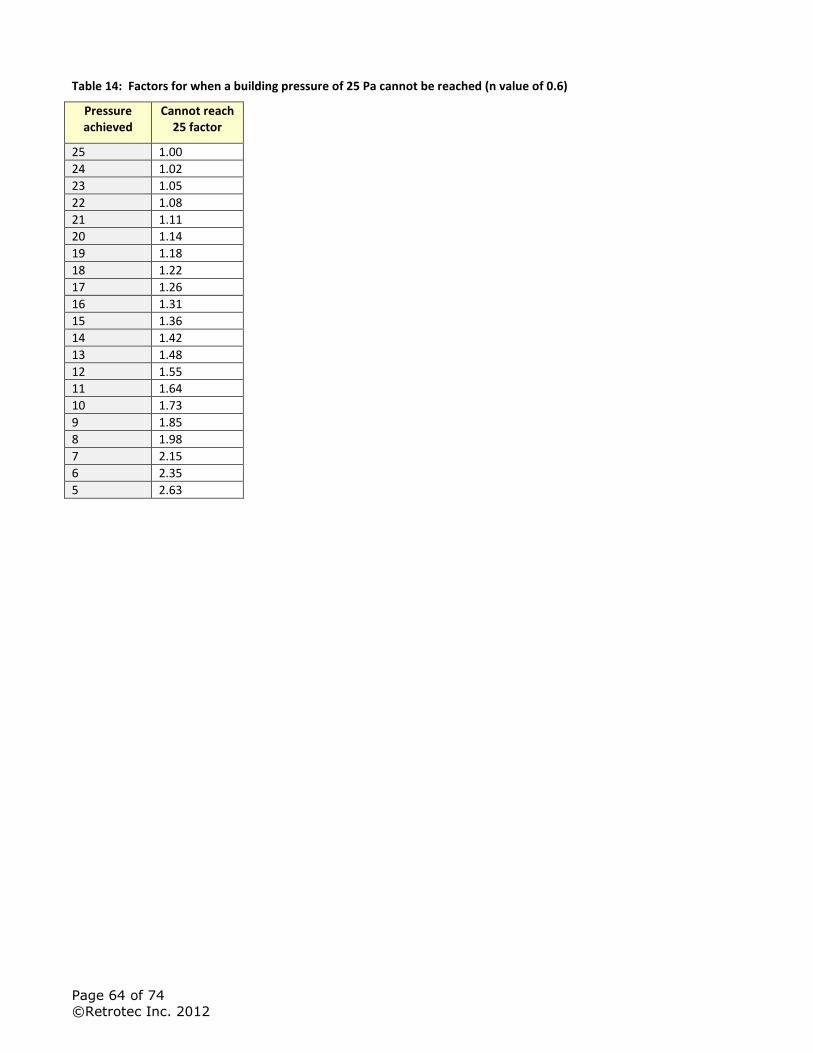
Page 64 of 74
©Retrotec Inc. 2012
Table 14: Factors for when a building pressure of 25 Pa cannot be reached (n value of 0.6)
Pressure achieved
Cannot reach 25 factor
25 1.00
24 1.02
23 1.05
22 1.08
21 1.11
20 1.14
19 1.18
18 1.22
17 1.26
16 1.31
15 1.36
14 1.42
13 1.48
12 1.55
11 1.64
10 1.73
9 1.85
8 1.98
7 2.15
6 2.35
5 2.63
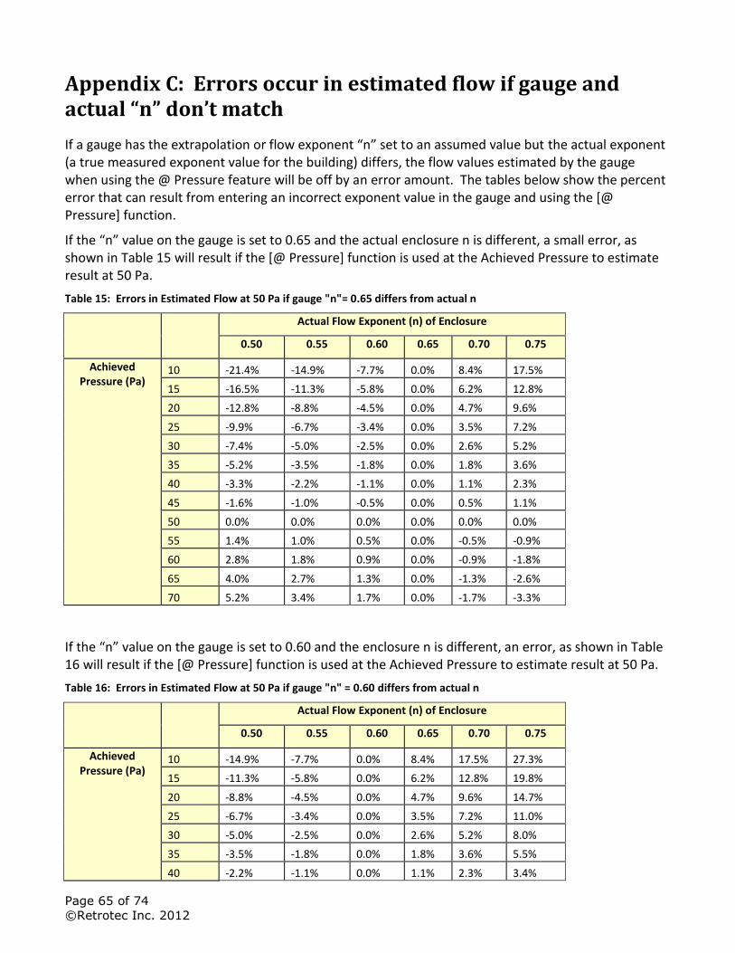
Page 65 of 74
©Retrotec Inc. 2012
Appendix C: Errors occur in estimated flow if gauge and actual “n” don’t match
If a gauge has the extrapolation or flow exponent “n” set to an assumed value but the actual exponent (a true measured exponent value for the building) differs, the flow values estimated by the gauge when using the @ Pressure feature will be off by an error amount. The tables below show the percent error that can result from entering an incorrect exponent value in the gauge and using the [@ Pressure] function.
If the “n” value on the gauge is set to 0.65 and the actual enclosure n is different, a small error, as shown in Table 15 will result if the [@ Pressure] function is used at the Achieved Pressure to estimate result at 50 Pa.
Table 15: Errors in Estimated Flow at 50 Pa if gauge "n"= 0.65 differs from actual n
Actual Flow Exponent (n) of Enclosure
0.50 0.55 0.60 0.65 0.70 0.75
Achieved Pressure (Pa)
10 -21.4% -14.9% -7.7% 0.0% 8.4% 17.5%
15 -16.5% -11.3% -5.8% 0.0% 6.2% 12.8%
20 -12.8% -8.8% -4.5% 0.0% 4.7% 9.6%
25 -9.9% -6.7% -3.4% 0.0% 3.5% 7.2%
30 -7.4% -5.0% -2.5% 0.0% 2.6% 5.2%
35 -5.2% -3.5% -1.8% 0.0% 1.8% 3.6%
40 -3.3% -2.2% -1.1% 0.0% 1.1% 2.3%
45 -1.6% -1.0% -0.5% 0.0% 0.5% 1.1%
50 0.0% 0.0% 0.0% 0.0% 0.0% 0.0%
55 1.4% 1.0% 0.5% 0.0% -0.5% -0.9%
60 2.8% 1.8% 0.9% 0.0% -0.9% -1.8%
65 4.0% 2.7% 1.3% 0.0% -1.3% -2.6%
70 5.2% 3.4% 1.7% 0.0% -1.7% -3.3%
If the “n” value on the gauge is set to 0.60 and the enclosure n is different, an error, as shown in Table 16 will result if the [@ Pressure] function is used at the Achieved Pressure to estimate result at 50 Pa.
Table 16: Errors in Estimated Flow at 50 Pa if gauge "n" = 0.60 differs from actual n
Actual Flow Exponent (n) of Enclosure
0.50 0.55 0.60 0.65 0.70 0.75
Achieved Pressure (Pa)
10 -14.9% -7.7% 0.0% 8.4% 17.5% 27.3%
15 -11.3% -5.8% 0.0% 6.2% 12.8% 19.8%
20 -8.8% -4.5% 0.0% 4.7% 9.6% 14.7%
25 -6.7% -3.4% 0.0% 3.5% 7.2% 11.0%
30 -5.0% -2.5% 0.0% 2.6% 5.2% 8.0%
35 -3.5% -1.8% 0.0% 1.8% 3.6% 5.5%
40 -2.2% -1.1% 0.0% 1.1% 2.3% 3.4%
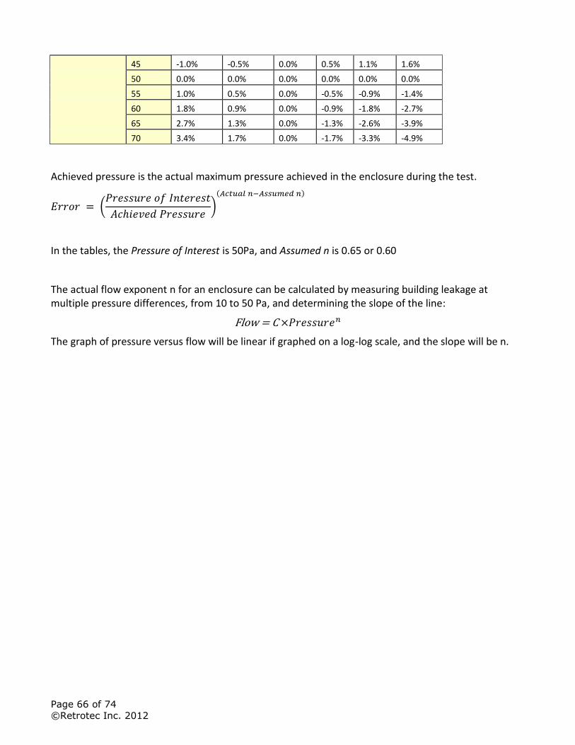
Page 66 of 74
©Retrotec Inc. 2012
45 -1.0% -0.5% 0.0% 0.5% 1.1% 1.6%
50 0.0% 0.0% 0.0% 0.0% 0.0% 0.0%
55 1.0% 0.5% 0.0% -0.5% -0.9% -1.4%
60 1.8% 0.9% 0.0% -0.9% -1.8% -2.7%
65 2.7% 1.3% 0.0% -1.3% -2.6% -3.9%
70 3.4% 1.7% 0.0% -1.7% -3.3% -4.9%
Achieved pressure is the actual maximum pressure achieved in the enclosure during the test.
(
)
( )
In the tables, the Pressure of Interest is 50Pa, and Assumed n is 0.65 or 0.60
The actual flow exponent n for an enclosure can be calculated by measuring building leakage at multiple pressure differences, from 10 to 50 Pa, and determining the slope of the line:
The graph of pressure versus flow will be linear if graphed on a log-log scale, and the slope will be n.

Page 67 of 74
©Retrotec Inc. 2012
Appendix D: Adjust Flow values for temperature difference
Temperature correction is only required when there is a temperature difference between the area under test, (inside), and the area used as reference for the test, (outside).
To use the tables, determine if you are pressurizing or pressurizing. When pressurizing, the air flow of the fan will be toward the inside, and when depressurizing, the air flow will be toward the outside.
Choose the correction factor from Table 17 for the depressurize case or Table 18 for the pressurize case based on the current inside and outside temperatures. Multiply the flow you measured by the factor to get the air flow corrected for temperature difference.
Retrotec’s FanTestic software automatically corrects flow values for any temperature difference when inside and outside temperatures are entered into the software.
Table 17: Temperature correction factors for enclosure DEPRESSURIZATION
50 55 60 65 70 75 80 85 90
-20 0.848 0.844 0.840 0.836 0.832 0.828 0.824 0.820 0.816
-15 0.857 0.853 0.849 0.845 0.841 0.837 0.833 0.829 0.826
-10 0.867 0.863 0.859 0.855 0.851 0.847 0.843 0.839 0.835
-5 0.877 0.872 0.868 0.864 0.860 0.856 0.852 0.848 0.844
0 0.886 0.882 0.878 0.874 0.869 0.865 0.861 0.857 0.854
5 0.896 0.892 0.887 0.883 0.879 0.875 0.871 0.867 0.863
10 0.906 0.901 0.897 0.893 0.888 0.884 0.880 0.876 0.872
15 0.915 0.911 0.906 0.902 0.898 0.894 0.890 0.885 0.881
20 0.925 0.920 0.916 0.912 0.907 0.903 0.899 0.895 0.891
25 0.935 0.930 0.926 0.921 0.917 0.912 0.908 0.904 0.900
30 0.944 0.940 0.935 0.931 0.926 0.922 0.918 0.913 0.909
35 0.954 0.949 0.945 0.940 0.936 0.931 0.927 0.923 0.919
40 0.964 0.959 0.954 0.950 0.945 0.941 0.936 0.932 0.928
45 0.973 0.968 0.964 0.959 0.955 0.950 0.946 0.941 0.937
50 0.983 0.978 0.973 0.969 0.964 0.960 0.955 0.951 0.946
55 0.992 0.988 0.983 0.978 0.974 0.969 0.964 0.960 0.956
60 1.002 0.997 0.992 0.988 0.983 0.978 0.974 0.969 0.965
65 1.012 1.007 1.002 0.997 0.992 0.988 0.983 0.979 0.974
70 1.021 1.016 1.011 1.007 1.002 0.997 0.993 0.988 0.983
75 1.031 1.026 1.021 1.016 1.011 1.007 1.002 0.997 0.993
80 1.041 1.036 1.031 1.026 1.021 1.016 1.011 1.007 1.002
85 1.050 1.045 1.040 1.035 1.030 1.025 1.021 1.016 1.011
90 1.060 1.055 1.050 1.045 1.040 1.035 1.030 1.025 1.021
95 1.070 1.064 1.059 1.054 1.049 1.044 1.039 1.035 1.030
100 1.079 1.074 1.069 1.064 1.059 1.054 1.049 1.044 1.039
105 1.089 1.084 1.078 1.073 1.068 1.063 1.058 1.053 1.048
110 1.098 1.093 1.088 1.083 1.078 1.073 1.068 1.063 1.058
Inside Temperature (F)
Ou
tsid
e T
em
pera
ture
(F
)
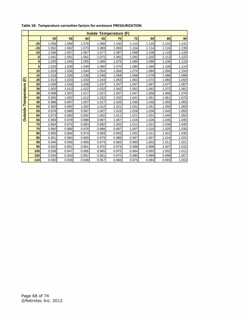
Page 68 of 74
©Retrotec Inc. 2012
Table 18: Temperature correction factors for enclosure PRESSURIZATION
50 55 60 65 70 75 80 85 90
-20 1.058 1.069 1.079 1.089 1.100 1.110 1.120 1.131 1.141
-15 1.052 1.062 1.073 1.083 1.093 1.104 1.114 1.124 1.135
-10 1.046 1.057 1.067 1.077 1.087 1.098 1.108 1.118 1.128
-5 1.041 1.051 1.061 1.071 1.081 1.092 1.102 1.112 1.122
0 1.035 1.045 1.055 1.065 1.075 1.086 1.096 1.106 1.116
5 1.029 1.039 1.049 1.060 1.070 1.080 1.090 1.100 1.110
10 1.024 1.034 1.044 1.054 1.064 1.074 1.084 1.094 1.104
15 1.018 1.028 1.038 1.048 1.058 1.068 1.078 1.088 1.098
20 1.013 1.023 1.033 1.043 1.053 1.063 1.073 1.083 1.093
25 1.008 1.018 1.028 1.037 1.047 1.057 1.067 1.077 1.087
30 1.003 1.013 1.022 1.032 1.042 1.052 1.062 1.072 1.081
35 0.998 1.007 1.017 1.027 1.037 1.047 1.056 1.066 1.076
40 0.993 1.002 1.012 1.022 1.032 1.041 1.051 1.061 1.070
45 0.988 0.997 1.007 1.017 1.026 1.036 1.046 1.055 1.065
50 0.983 0.992 1.002 1.012 1.021 1.031 1.041 1.050 1.060
55 0.978 0.988 0.997 1.007 1.016 1.026 1.036 1.045 1.055
60 0.973 0.983 0.992 1.002 1.011 1.021 1.031 1.040 1.050
65 0.969 0.978 0.988 0.997 1.007 1.016 1.026 1.035 1.045
70 0.964 0.974 0.983 0.992 1.002 1.011 1.021 1.030 1.040
75 0.960 0.969 0.978 0.988 0.997 1.007 1.016 1.025 1.035
80 0.955 0.964 0.974 0.983 0.993 1.002 1.011 1.021 1.030
85 0.951 0.960 0.969 0.979 0.988 0.997 1.007 1.016 1.025
90 0.946 0.956 0.965 0.974 0.983 0.993 1.002 1.011 1.021
95 0.942 0.951 0.961 0.970 0.979 0.988 0.998 1.007 1.016
100 0.938 0.947 0.956 0.965 0.975 0.984 0.993 1.002 1.011
105 0.934 0.943 0.952 0.961 0.970 0.980 0.989 0.998 1.007
110 0.930 0.939 0.948 0.957 0.966 0.975 0.984 0.993 1.003
Inside Temperature (F)
Ou
tsid
e T
em
pera
ture
(F
)

Page 69 of 74
©Retrotec Inc. 2012
Appendix E: Tables to correct Flow if range selected did not match installed range
If the range installed was different than the range selected on the gauge then the following tables can be used to determine the correct flow, as long as the fan was blowing Away from the operator, which is depressurizing from the inside or pressurizing from the outside.
The gauge converts the fan pressure to CFM based on the Range Configuration selected on the gauge. If you realize that you have recorded results while the selected Range Configuration is different than what was installed in the fan, look up the recorded flow on the Flow Conversion tables for the Device and read across to the correct range column to determine what the result would have been if you have put the gauge on the correct Range.
Use the Flow Conversion Chart for your fan to locate the correct results as follows:
In this example you were testing with a DU200 DucTester with “Range Config” on the gauge set to Mid. Later you remembered your DucTester actually had the Low Range Ring attached. You recorded 33 CFM.
Find the 33 CFM you recorded under the “Mid“column for Range on the Flow Conversion Table. Then, just move over to read the correct result under the “Low” column for Range. In this case it will be 7.1 CFM.
Here is where to find those tables depending on the type of system you are using:
For Blower Doors see: Door Fan Operation Manual, Appendix D: Flow Conversion Tables
http://retrotec.com/Portals/5/Documents/Manuals/Manual-Door%20Fan%20Operation.pdf
For DucTesters see: DucTester Operation & Testing Manual, Appendix C: Flow Tables
http://retrotec.com/Downloads/WebsitePDFs/Manual-DucTester%20Operation%20&%20Testing.pdf

Page 70 of 74
©Retrotec Inc. 2012
Watch this quick video on choosing the wrong range and how to recognize it:
Video (image): http://www.youtube.com/watch?v=JP1RsL3pm8E&list=UUr-qgIDfAh9wq88Pye4vE8w&index=48&feature=plpp_video
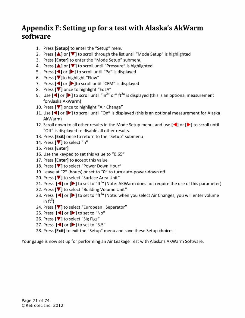
Page 71 of 74
©Retrotec Inc. 2012
Appendix F: Setting up for a test with Alaska’s AkWarm software
1. Press [Setup] to enter the “Setup” menu 2. Press [] or [] to scroll through the list until “Mode Setup” is highlighted 3. Press [Enter] to enter the “Mode Setup” submenu 4. Press [] or [] to scroll until “Pressure” is highlighted. 5. Press [] or [] to scroll until “Pa” is displayed 6. Press []to highlight “Flow” 7. Press [] or []to scroll until “CFM” is displayed 8. Press [] once to highlight “EqLA” 9. Use [] or [] to scroll until “in2” or” ft2” is displayed (this is an optional measurement
forAlaska AkWarm) 10. Press [] once to highlight “Air Change” 11. Use [] or [] to scroll until “On” is displayed (this is an optional measurement for Alaska
AkWarm) 12. Scroll down to all other results in the Mode Setup menu, and use [] or [] to scroll until
“Off” is displayed to disable all other results. 13. Press [Exit] once to return to the “Setup” submenu 14. Press [] to select “n” 15. Press [Enter] 16. Use the keypad to set this value to “0.65” 17. Press [Enter] to accept this value 18. Press [] to select “Power Down Hour” 19. Leave at “2” (hours) or set to “0” to turn auto-power-down off. 20. Press [] to select “Surface Area Unit” 21. Press [] or [] to set to “ft2” (Note: AKWarm does not require the use of this parameter) 22. Press [] to select “Building Volume Unit” 23. Press [] or [] to set to “ft3” (Note: when you select Air Changes, you will enter volume
in ft3) 24. Press [] to select “European , Separator” 25. Press [] or [] to set to “No” 26. Press [] to select “Sig Figs” 27. Press [] or [] to set to “3.5” 28. Press [Exit] to exit the “Setup” menu and save these Setup choices.
Your gauge is now set up for performing an Air Leakage Test with Alaska’s AKWarm Software.
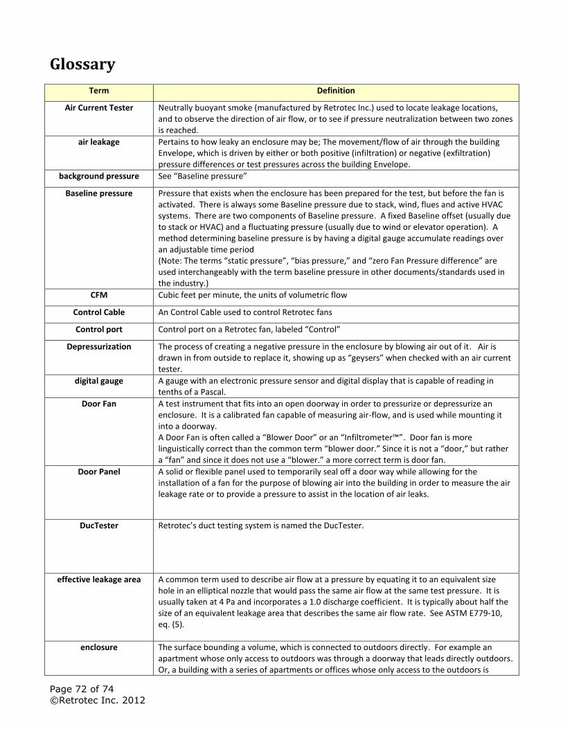
Page 72 of 74
©Retrotec Inc. 2012
Glossary
Term Definition
Air Current Tester Neutrally buoyant smoke (manufactured by Retrotec Inc.) used to locate leakage locations, and to observe the direction of air flow, or to see if pressure neutralization between two zones is reached.
air leakage Pertains to how leaky an enclosure may be; The movement/flow of air through the building Envelope, which is driven by either or both positive (infiltration) or negative (exfiltration) pressure differences or test pressures across the building Envelope.
background pressure See “Baseline pressure”
Baseline pressure Pressure that exists when the enclosure has been prepared for the test, but before the fan is activated. There is always some Baseline pressure due to stack, wind, flues and active HVAC systems. There are two components of Baseline pressure. A fixed Baseline offset (usually due to stack or HVAC) and a fluctuating pressure (usually due to wind or elevator operation). A method determining baseline pressure is by having a digital gauge accumulate readings over an adjustable time period (Note: The terms “static pressure”, “bias pressure,” and “zero Fan Pressure difference” are used interchangeably with the term baseline pressure in other documents/standards used in the industry.)
CFM Cubic feet per minute, the units of volumetric flow
Control Cable An Control Cable used to control Retrotec fans
Control port Control port on a Retrotec fan, labeled “Control”
Depressurization The process of creating a negative pressure in the enclosure by blowing air out of it. Air is drawn in from outside to replace it, showing up as “geysers” when checked with an air current tester.
digital gauge A gauge with an electronic pressure sensor and digital display that is capable of reading in tenths of a Pascal.
Door Fan A test instrument that fits into an open doorway in order to pressurize or depressurize an enclosure. It is a calibrated fan capable of measuring air-flow, and is used while mounting it into a doorway. A Door Fan is often called a “Blower Door” or an “Infiltrometer™”. Door fan is more linguistically correct than the common term “blower door.” Since it is not a “door,” but rather a “fan” and since it does not use a “blower.” a more correct term is door fan.
Door Panel A solid or flexible panel used to temporarily seal off a door way while allowing for the installation of a fan for the purpose of blowing air into the building in order to measure the air leakage rate or to provide a pressure to assist in the location of air leaks.
DucTester Retrotec’s duct testing system is named the DucTester.
effective leakage area A common term used to describe air flow at a pressure by equating it to an equivalent size hole in an elliptical nozzle that would pass the same air flow at the same test pressure. It is usually taken at 4 Pa and incorporates a 1.0 discharge coefficient. It is typically about half the size of an equivalent leakage area that describes the same air flow rate. See ASTM E779-10, eq. (5).
enclosure The surface bounding a volume, which is connected to outdoors directly. For example an apartment whose only access to outdoors was through a doorway that leads directly outdoors. Or, a building with a series of apartments or offices whose only access to the outdoors is
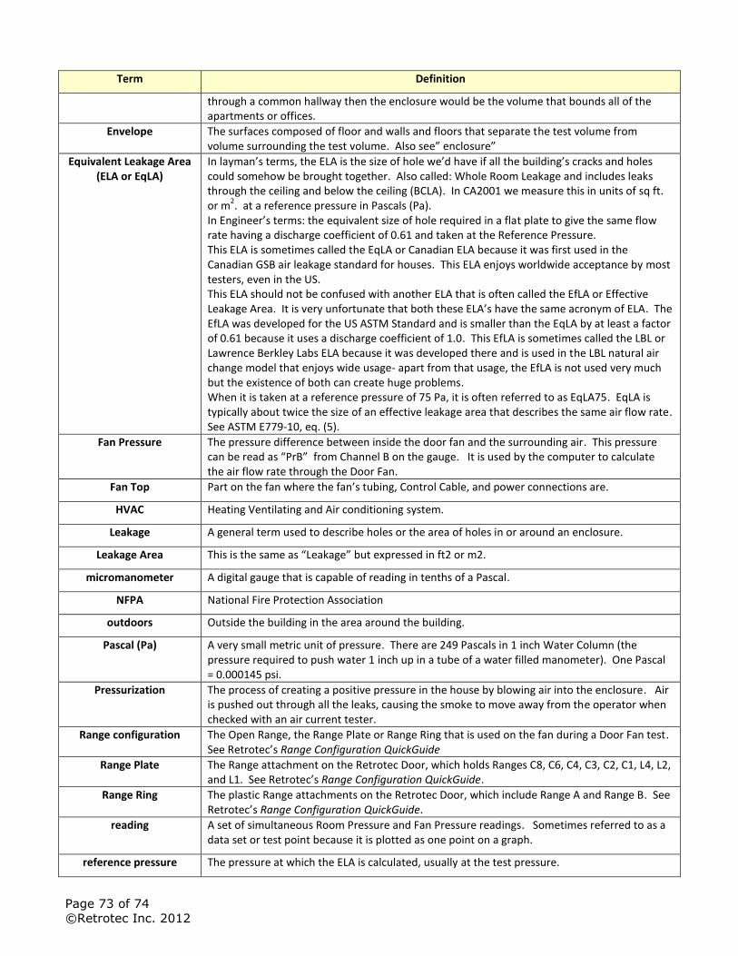
Page 73 of 74
©Retrotec Inc. 2012
Term Definition
through a common hallway then the enclosure would be the volume that bounds all of the apartments or offices.
Envelope The surfaces composed of floor and walls and floors that separate the test volume from volume surrounding the test volume. Also see” enclosure”
Equivalent Leakage Area (ELA or EqLA)
In layman’s terms, the ELA is the size of hole we’d have if all the building’s cracks and holes could somehow be brought together. Also called: Whole Room Leakage and includes leaks through the ceiling and below the ceiling (BCLA). In CA2001 we measure this in units of sq ft. or m
2. at a reference pressure in Pascals (Pa).
In Engineer’s terms: the equivalent size of hole required in a flat plate to give the same flow rate having a discharge coefficient of 0.61 and taken at the Reference Pressure. This ELA is sometimes called the EqLA or Canadian ELA because it was first used in the Canadian GSB air leakage standard for houses. This ELA enjoys worldwide acceptance by most testers, even in the US. This ELA should not be confused with another ELA that is often called the EfLA or Effective Leakage Area. It is very unfortunate that both these ELA’s have the same acronym of ELA. The EfLA was developed for the US ASTM Standard and is smaller than the EqLA by at least a factor of 0.61 because it uses a discharge coefficient of 1.0. This EfLA is sometimes called the LBL or Lawrence Berkley Labs ELA because it was developed there and is used in the LBL natural air change model that enjoys wide usage- apart from that usage, the EfLA is not used very much but the existence of both can create huge problems. When it is taken at a reference pressure of 75 Pa, it is often referred to as EqLA75. EqLA is typically about twice the size of an effective leakage area that describes the same air flow rate. See ASTM E779-10, eq. (5).
Fan Pressure The pressure difference between inside the door fan and the surrounding air. This pressure can be read as “PrB” from Channel B on the gauge. It is used by the computer to calculate the air flow rate through the Door Fan.
Fan Top Part on the fan where the fan’s tubing, Control Cable, and power connections are.
HVAC Heating Ventilating and Air conditioning system.
Leakage A general term used to describe holes or the area of holes in or around an enclosure.
Leakage Area This is the same as “Leakage” but expressed in ft2 or m2.
micromanometer A digital gauge that is capable of reading in tenths of a Pascal.
NFPA National Fire Protection Association
outdoors Outside the building in the area around the building.
Pascal (Pa)
A very small metric unit of pressure. There are 249 Pascals in 1 inch Water Column (the pressure required to push water 1 inch up in a tube of a water filled manometer). One Pascal = 0.000145 psi.
Pressurization
The process of creating a positive pressure in the house by blowing air into the enclosure. Air is pushed out through all the leaks, causing the smoke to move away from the operator when checked with an air current tester.
Range configuration The Open Range, the Range Plate or Range Ring that is used on the fan during a Door Fan test. See Retrotec’s Range Configuration QuickGuide
Range Plate The Range attachment on the Retrotec Door, which holds Ranges C8, C6, C4, C3, C2, C1, L4, L2, and L1. See Retrotec’s Range Configuration QuickGuide.
Range Ring The plastic Range attachments on the Retrotec Door, which include Range A and Range B. See Retrotec’s Range Configuration QuickGuide.
reading
A set of simultaneous Room Pressure and Fan Pressure readings. Sometimes referred to as a data set or test point because it is plotted as one point on a graph.
reference pressure The pressure at which the ELA is calculated, usually at the test pressure.
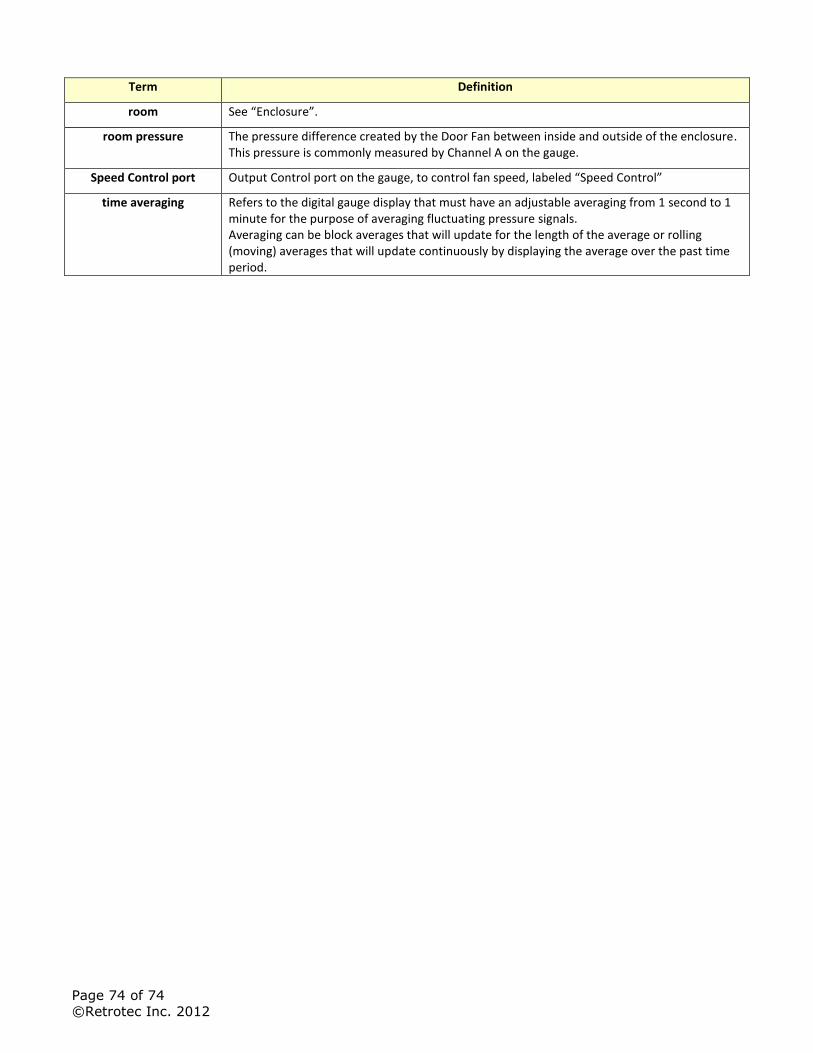
Page 74 of 74
©Retrotec Inc. 2012
Term Definition
room See “Enclosure”.
room pressure
The pressure difference created by the Door Fan between inside and outside of the enclosure. This pressure is commonly measured by Channel A on the gauge.
Speed Control port Output Control port on the gauge, to control fan speed, labeled “Speed Control”
time averaging Refers to the digital gauge display that must have an adjustable averaging from 1 second to 1 minute for the purpose of averaging fluctuating pressure signals. Averaging can be block averages that will update for the length of the average or rolling (moving) averages that will update continuously by displaying the average over the past time period.


![No Model VIN 1 (DM) SANTAFE [DM] KMHSU81BSCU000212 2 … Engine YF and D… · 37 (dm) santafe [dm] kmhst81bsdu023920 38 (dm) santafe [dm] kmhst81bsdu023926 39 (dm) santafe [dm] kmhst81bsdu023930](https://img.pdfslide.us/doc/110x75/6017564e29e54a6dde7ebe6b/no-model-vin-1-dm-santafe-dm-kmhsu81bscu000212-2-engine-yf-and-d-37-dm-santafe.jpg)


![µ } [ µ ]v ^ Z}}orWo u v - ABSµ } [ µ ]v ^ Z}}orWo u v DM-12-008 SatyaSai Kruti Stockholding Corporation of India Ltd DM-12-009 Goda Devi T P Libsys Inc DM-12-011 Bhanu Thanuja](https://img.pdfslide.us/doc/110x75/5e82173fdc28cb2b592a1215/-v-zorwo-u-v-abs-v-zorwo-u-v-dm-12-008-satyasai-kruti.jpg)