Embed Size (px)
Citation preview
HAL Id: hal-02295012https://hal.archives-ouvertes.fr/hal-02295012
Submitted on 24 Sep 2019
HAL is a multi-disciplinary open accessarchive for the deposit and dissemination of sci-entific research documents, whether they are pub-lished or not. The documents may come fromteaching and research institutions in France orabroad, or from public or private research centers.
L’archive ouverte pluridisciplinaire HAL, estdestinée au dépôt et à la diffusion de documentsscientifiques de niveau recherche, publiés ou non,émanant des établissements d’enseignement et derecherche français ou étrangers, des laboratoirespublics ou privés.
Retinal image processing in BiometricsRostom Kachouri, Mohamed Akil, Yaroub Elloumi
To cite this version:Rostom Kachouri, Mohamed Akil, Yaroub Elloumi. Retinal image processing in Biometrics. AmineNait-Ali. Hidden Biometrics _ When Biometric Security Meets Biomedical Engineering, 2019, 978-981-13-0956-4. �10.1007/978-981-13-0956-4_10�. �hal-02295012�
Chapter 10. Retinal image processing in Biometrics
Rostom Kachouria(*), Mohamed Akil1, Yaroub Elloumi1,2,3
1Gaspard Monge Computer Science Laboratory, ESIEE-Paris, University Paris-Est Marne-la-Vallée, France. 2Medical Technology and Image Processing Laboratory, Faculty of medicine, University of Monastir, Tunisia. 3ISITCom Hammam-Sousse, University of Sousse, Tunisia. (*) Corresponding author: [email protected]
Abstract ( will not be included in this chapter)
In this chapter, retinal image processing will be addressed as a Hidden Biometric modality. Considered as safe modalities, the retinal vascular network provide a unique pattern for each individual since it does not change throughout the life of the person. In addition, the retina offers a high level of recognition, which makes it suitable for high security applications thanks to its universality, its invariability over time and its difficulty to falsify.
10.1. Introduction
Traditionally, the recognition of individuals is done either by the
knowledge of passwords or answers to secret questions, either by an access badge or a Custom smart card. However, each of these methods suffers from a set of problems such as loss, forgetfulness and reproduction. Nowadays, the use of biometric recognition has become more and more a requirement for dealing with growing insecurity problems. Generally, biometric characteristics are classified into three major modalities: behavioral, biological and morphological. The morphological modality may be based on specific physical traits such as fingerprint, face, palm print, retina, etc. The biological modality may be based on the analysis of biological traces such as odor, saliva or DNA. While the behavioral modality is based on the analysis of
2
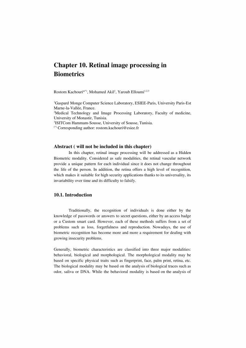
certain behaviors of people like the voice, the signature, the manner of walking, etc. In this chapter, we are interested in one of the most morphological modalities, particularly, Retinal image processing in Biometrics. Indeed, Retinal is one of the safest modalities because of its protection inside the eye. Moreover, the retinal vascular network is a unique model of each individual and does not change throughout the life of the person. In addition, the retina offers a high level of recognition, which makes it suitable for high security applications thanks to its universality, its invariability over time and its difficulty to falsify. The anatomy of Retina (figure 1) has a rich structure containing many characteristics and retinal components such as the optic disk, the cup, the macula and the fovea. In addition, the retina is traversed by blood vessels. The optic disc, where blood vessels converge, is characterized especially by the brightest area called Cup. On the other hand, the macula has the darkest part (fovea) of the retinal image. It is surrounded on each side by the vascular system from both upper and lower arteries. As illustrated in figure 1, the segment FD connects the fovea and the boundary of the optic disc. It is located on the line called the Raphe of the retina, which separates the inferior retinal region and the superior one. According to the retina anatomy (figure 1), the slice FD is equal to two Optic Disc diameters.
Figure 1: Retina anatomy.
At first, Retinal Imaging plays a key role including the diagnosis and treatment of the ocular diseases [1]. It is in this area where much of the retinal capture devices developed both in field of research and in companies. Scientific and technological innovations in the design of retinal capture devices can contribute significantly to develop the Retina based identification systems.
3
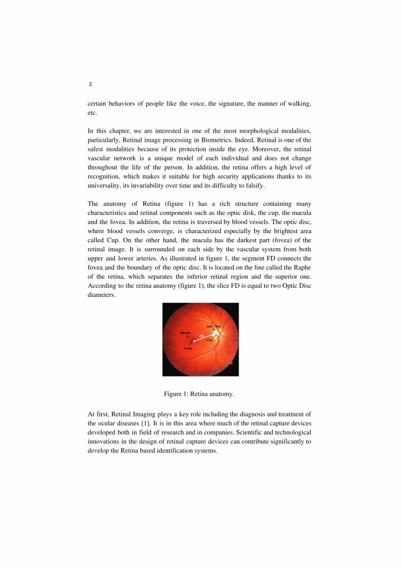
The Retina based identification is perceived as the most secure method of authenticating an identity. Every eye has its own pattern of blood vessels. Thus, the retinal vasculature is a reliable biometric parameter, since each person’s eye is known to have a unique arrangement of blood vessels in the retina [2], [3]. Moreover, retinal based identification provides a high level of accuracy. It is well suited for high-security applications. It is reputed to be very reliable and difficult to falsify. The following figure (figure 2) shows the different processing stages of the retina-based identification system.
Figure 2: main steps of retina-based identification system. The rest of this chapter is organized as follows: Section 2 presents an overview of existing Retinal imaging and capture devices. Retinal features for biometry and related works of existing retinal recognition systems are described in section 3. In section 4, we present some ocular pathologies affecting retinal components in biometric field. Finally, conclusion is drawn in the last section.
10.2. Retinal capture device
The retina is the sensory layer of the eye that allows vision. It is captured using a biometric scanner that uses a visible beam of light to trace a circular path on the retina to the back of the eye. Once the eyes are illuminated, a scan is performed to
4
capture the features of the retina. So, in the beginning, this process is therefore invasive, uncomfortable, and difficult to implement. As a result, the acquisition systems have been improved over time. A near-infrared light source replaced the visible light source. The amount of energy radiated by this source as well as the acquisition time have decreased more and more with each new retinal capture device system. We present in this section, an overview of existing Retinal imaging and capture devices.
10.2.1. Retinal Imaging Modalities
Retinal imaging devices are primarily used in the earlier screening and diagnosis of ocular (retinal) diseases. The principal imaging technologies for the retina, are scanning laser ophthalmoscopy (Scanning laser ophthalmoscope - SLO) [4] and Optical Coherence Tomography (OCT) [5] and fundus camera imaging [6]. In the following, we present the main characteristics of these imaging modalities.
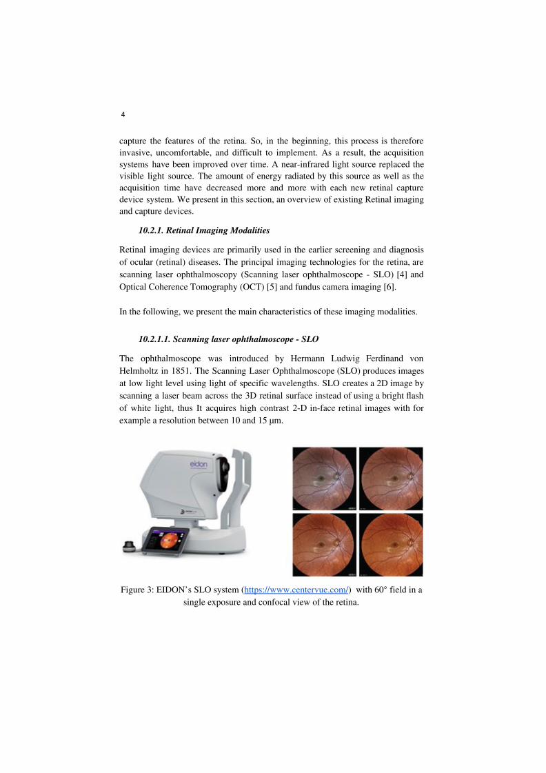
10.2.1.1. Scanning laser ophthalmoscope - SLO
The ophthalmoscope was introduced by Hermann Ludwig Ferdinand von Helmholtz in 1851. The Scanning Laser Ophthalmoscope (SLO) produces images at low light level using light of specific wavelengths. SLO creates a 2D image by scanning a laser beam across the 3D retinal surface instead of using a bright flash of white light, thus It acquires high contrast 2-D in-face retinal images with for example a resolution between 10 and 15 µm.
Figure 3: EIDON’s SLO system (https://www.centervue.com/) with 60° field in a
single exposure and confocal view of the retina.
5
Let us remember that the first Optical Coherence Tomography (OCT) system was designed at MIT Lincoln Laboratory in 1993.
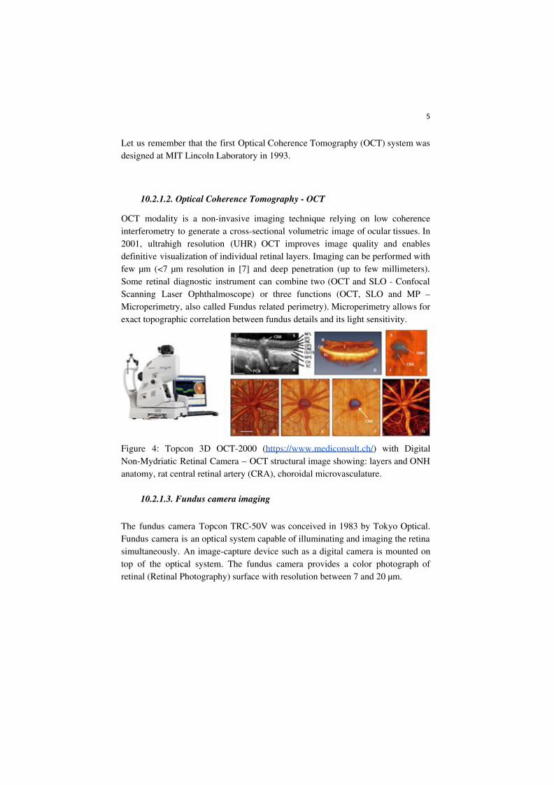
10.2.1.2. Optical Coherence Tomography - OCT
OCT modality is a non-invasive imaging technique relying on low coherence interferometry to generate a cross-sectional volumetric image of ocular tissues. In 2001, ultrahigh resolution (UHR) OCT improves image quality and enables definitive visualization of individual retinal layers. Imaging can be performed with few µm (<7 µm resolution in [7] and deep penetration (up to few millimeters). Some retinal diagnostic instrument can combine two (OCT and SLO - Confocal Scanning Laser Ophthalmoscope) or three functions (OCT, SLO and MP – Microperimetry, also called Fundus related perimetry). Microperimetry allows for exact topographic correlation between fundus details and its light sensitivity.
Figure 4: Topcon 3D OCT-2000 (https://www.mediconsult.ch/) with Digital Non-Mydriatic Retinal Camera – OCT structural image showing: layers and ONH anatomy, rat central retinal artery (CRA), choroidal microvasculature.
10.2.1.3. Fundus camera imaging
The fundus camera Topcon TRC-50V was conceived in 1983 by Tokyo Optical. Fundus camera is an optical system capable of illuminating and imaging the retina simultaneously. An image-capture device such as a digital camera is mounted on top of the optical system. The fundus camera provides a color photograph of retinal (Retinal Photography) surface with resolution between 7 and 20 µm.
6
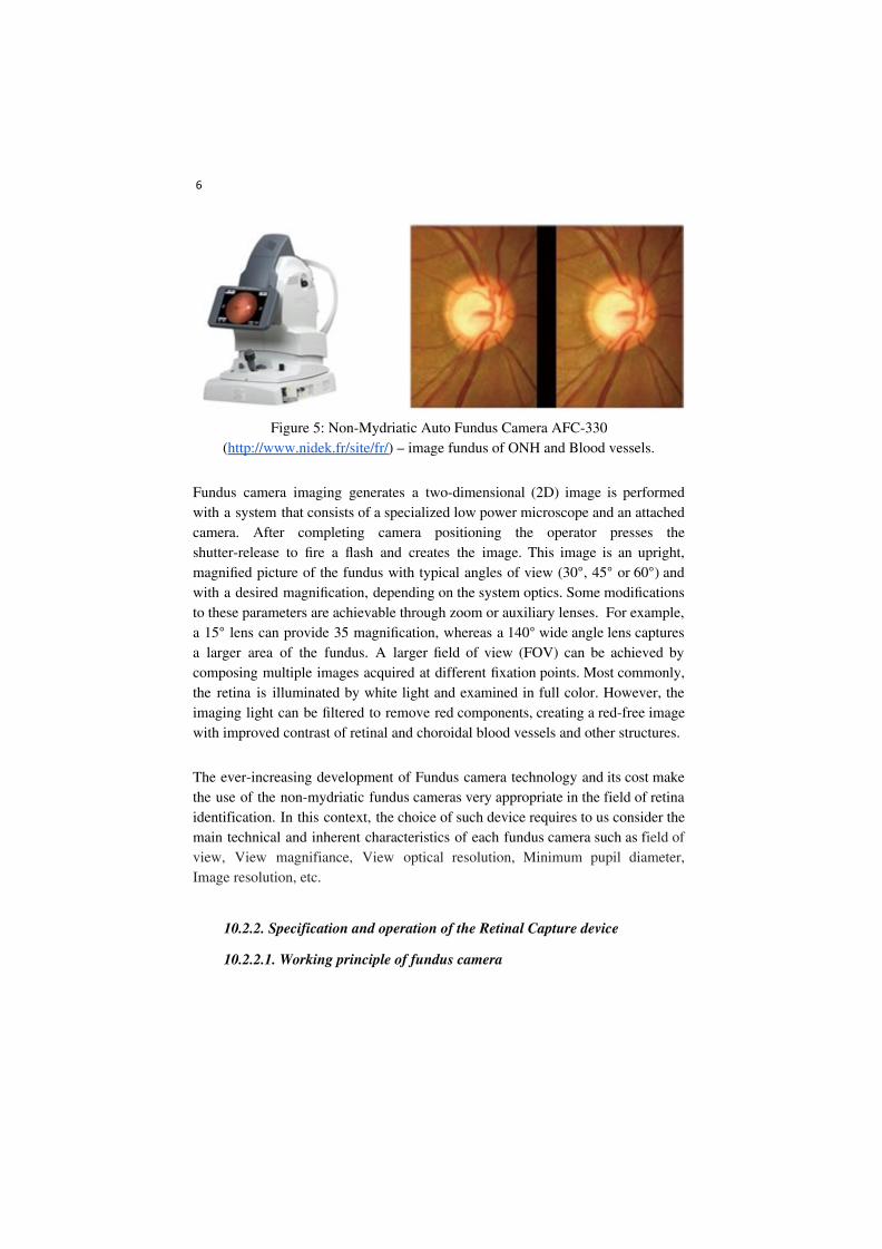
Figure 5: Non-Mydriatic Auto Fundus Camera AFC-330
(http://www.nidek.fr/site/fr/) – image fundus of ONH and Blood vessels.
Fundus camera imaging generates a two-dimensional (2D) image is performed with a system that consists of a specialized low power microscope and an attached camera. After completing camera positioning the operator presses the shutter-release to fire a flash and creates the image. This image is an upright, magnified picture of the fundus with typical angles of view (30°, 45° or 60°) and with a desired magnification, depending on the system optics. Some modifications to these parameters are achievable through zoom or auxiliary lenses. For example, a 15° lens can provide 35 magnification, whereas a 140° wide angle lens captures a larger area of the fundus. A larger field of view (FOV) can be achieved by composing multiple images acquired at different fixation points. Most commonly, the retina is illuminated by white light and examined in full color. However, the imaging light can be filtered to remove red components, creating a red-free image with improved contrast of retinal and choroidal blood vessels and other structures.
The ever-increasing development of Fundus camera technology and its cost make the use of the non-mydriatic fundus cameras very appropriate in the field of retina identification. In this context, the choice of such device requires to us consider the main technical and inherent characteristics of each fundus camera such as field of view, View magnifiance, View optical resolution, Minimum pupil diameter, Image resolution, etc.
10.2.2. Specification and operation of the Retinal Capture device
10.2.2.1. Working principle of fundus camera
7
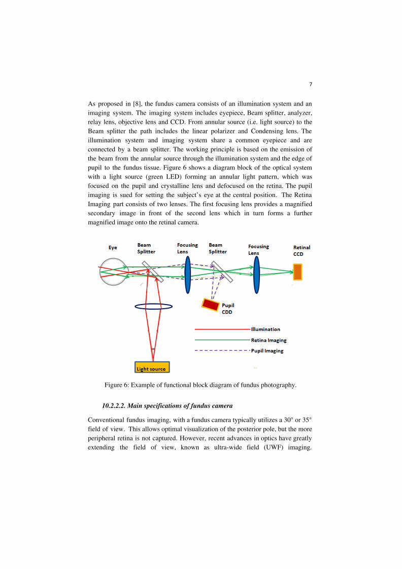
As proposed in [8], the fundus camera consists of an illumination system and an imaging system. The imaging system includes eyepiece, Beam splitter, analyzer, relay lens, objective lens and CCD. From annular source (i.e. light source) to the Beam splitter the path includes the linear polarizer and Condensing lens. The illumination system and imaging system share a common eyepiece and are connected by a beam splitter. The working principle is based on the emission of the beam from the annular source through the illumination system and the edge of pupil to the fundus tissue. Figure 6 shows a diagram block of the optical system with a light source (green LED) forming an annular light pattern, which was focused on the pupil and crystalline lens and defocused on the retina. The pupil imaging is sued for setting the subject’s eye at the central position. The Retina Imaging part consists of two lenses. The first focusing lens provides a magnified secondary image in front of the second lens which in turn forms a further magnified image onto the retinal camera.
Figure 6: Example of functional block diagram of fundus photography.
10.2.2.2. Main specifications of fundus camera
Conventional fundus imaging, with a fundus camera typically utilizes a 30° or 35° field of view. This allows optimal visualization of the posterior pole, but the more peripheral retina is not captured. However, recent advances in optics have greatly extending the field of view, known as ultra-wide field (UWF) imaging.
8
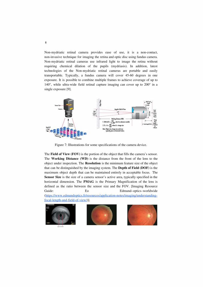
Non-mydriatic retinal camera provides ease of use, it is a non-contact, non-invasive technique for imaging the retina and optic disc using fundus camera. Non-mydriatic retinal cameras use infrared light to image the retina without requiring chemical dilation of the pupils (mydriasis). In addition, latest technologies of the Non-mydriatic retinal cameras are portable and easily transportable. Typically, a fundus camera will cover 45-60 degrees in one exposure. It is possible to combine multiple frames to achieve coverage of up to 140°, while ultra-wide field retinal capture imaging can cover up to 200° in a single exposure [9].
Figure 7: Illustrations for some specifications of the camera device.
The Field of View (FOV) is the portion of the object that fills the camera’s sensor. The Working Distance (WD) is the distance from the front of the lens to the object under inspection. The Resolution is the minimum feature size of the object that can be distinguished by the imaging system. The Depth of Field (DOF) is the maximum object depth that can be maintained entirely in acceptable focus. The Sensor Size is the size of a camera sensor’s active area, typically specified in the horizontal dimension. The PMAG is the Primary Magnification of the lens is defined as the ratio between the sensor size and the FOV. [Imaging Resource Guide: Eo Edmund–optics–worldwide (https://www.edmundoptics.fr/resources/application-notes/imaging/understanding-focal-length-and-field-of-view/)].
9
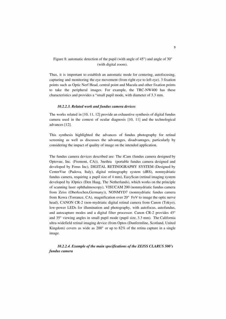
Figure 8: automatic detection of the pupil (with angle of 45°) and angle of 30°
(with digital zoom).
Thus, it is important to establish an automatic mode for centering, autofocusing, capturing and monitoring the eye movement (from right eye to left eye). 3 fixation points such as Optic Nerf Head, central point and Macula and other fixation points to take the peripheral images. For example, the TRC-NW400 has these characteristics and provides a “small pupil mode, with diameter of 3.3 mm.
10.2.2.3. Related work and fundus camera devices
The works related in [10, 11, 12] provide an exhaustive synthesis of digital fundus camera used in the context of ocular diagnosis [10, 11] and the technological advances [12]. This synthesis highlighted the advances of fundus photography for retinal screening as well as discusses the advantages, disadvantages, particularly by considering the impact of quality of image on the intended application.
The fundus camera devices described are: The iCam (fundus camera designed by Optovue, Inc. (Fremont, CA)), 3nethra (portable fundus camera designed and developed by Forus Inc), DIGITAL RETINOGRAPHY SYSTEM (Designed by CenterVue (Padova, Italy), digital retinography system (dRS), nonmydriatic fundus camera, requiring a pupil size of 4 mm), EasyScan (retinal imaging system developed by iOptics (Den Haag, The Netherlands), which works on the principle of scanning laser ophthalmoscopy), VISUCAM 200 (nonmydriatic fundus camera from Zeiss (Oberkochen,Germany)), NONMYD7 (nonmydriatic fundus camera from Kowa (Torrance, CA), magnification over 20° FoV to image the optic nerve head), CANON CR-2 (non-mydriatic digital retinal camera from Canon (Tokyo), low-power LEDs for illumination and photography, with autofocus, autofundus, and autocapture modes and a digital filter processor. Canon CR-2 provides 45° and 35° viewing angles in small pupil mode (pupil size, 3.3 mm). The California ultra-widefield retinal imaging device (from Optos (Dunfermline, Scotland, United Kingdom) covers as wide as 200° or up to 82% of the retina capture in a single image.
10.2.2.4. Example of the main specifications of the ZEISS CLARUS 500’s fundus camera
10
This fundus camera device captures true color imaging, high-resolution fundus autofluorescence (FAF) images–FAF-Blue and FAF-Green–and external eye images. The ultra-widefield mode captures a high-resolution image down to 7 microns and high-resolution details from the posterior pole to the periphery. All True Color images can be separated into red, green and blue channel images to help enhance the visual contrast of details in certain layers of the retina. The Field of View (measured from the center of the eye): Widefield (one image) 133˚, Ultra-widefield (two images) 200˚, Montage (up to six images) up to 267˚. The other characteristics are: Resolution: Optical (7.3 µm), Minimum Pupil Diameter ( 2.5 mm), Working Distance (25 mm, it’s patient’s eye to front lens) and Light Sources: Red LED (585 - 640 nm), Green LED (500 - 585 nm), Blue LED (435 - 500 nm) and Infrared laser diode (785 nm).
10.2.2.5. Non-mydriatic camera: portable device – device-based
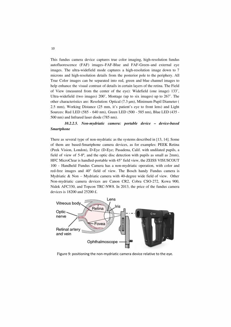
Smartphone There as several type of non-mydriatic as the systems described in [13, 14]. Some of them are based-Smartphone camera devices, as for examples: PEEK Retina (Peek Vision, London), D-Eye (D-Eye; Pasadena, Calif. with undilated pupils, a field of view of 5-8º, and the optic disc detection with pupils as small as 2mm), HFC MicroClear is handled-portable with 45° field view, the ZEISS VISUSCOUT 100 - Handheld Fundus Camera has a non-mydriatic operation, with color and red-free images and 40° field of view. The Bosch handy Fundus camera is Mydriatic & Non – Mydriatic camera with 40-degree wide field of view. Other Non-mydriatic camera devices are Canon CR2, Cobra CSO-272, Kowa 900, Nidek AFC330, and Topcon TRC-NW8. In 2013, the price of the fundus camera devices is 18200 and 25200 £.
Figure 9: positioning the non-mydriatic camera device relative to the eye.
11
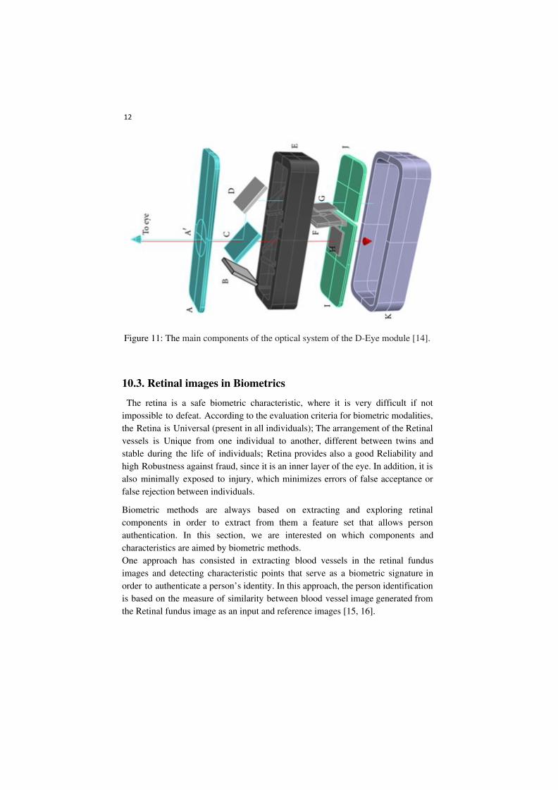
In [12] the view and the main components of the optical system of the D-Eye module are described. “Retinal images are acquired using coaxial illumination and imaging paths thanks to a beam splitter (C). The blue arrow depicts the path of the light; red arrow depicts the path of fundus imaging. Device components are glass platelet (A) with imprinted negative lens (A), photoabsorbing wall (B), beam splitter (C), mirror (D), plastic case (E),diaphragm (F), polarized filters (G, H), flash and camera glass (J, I), and magnetic external ring(K)” [14].
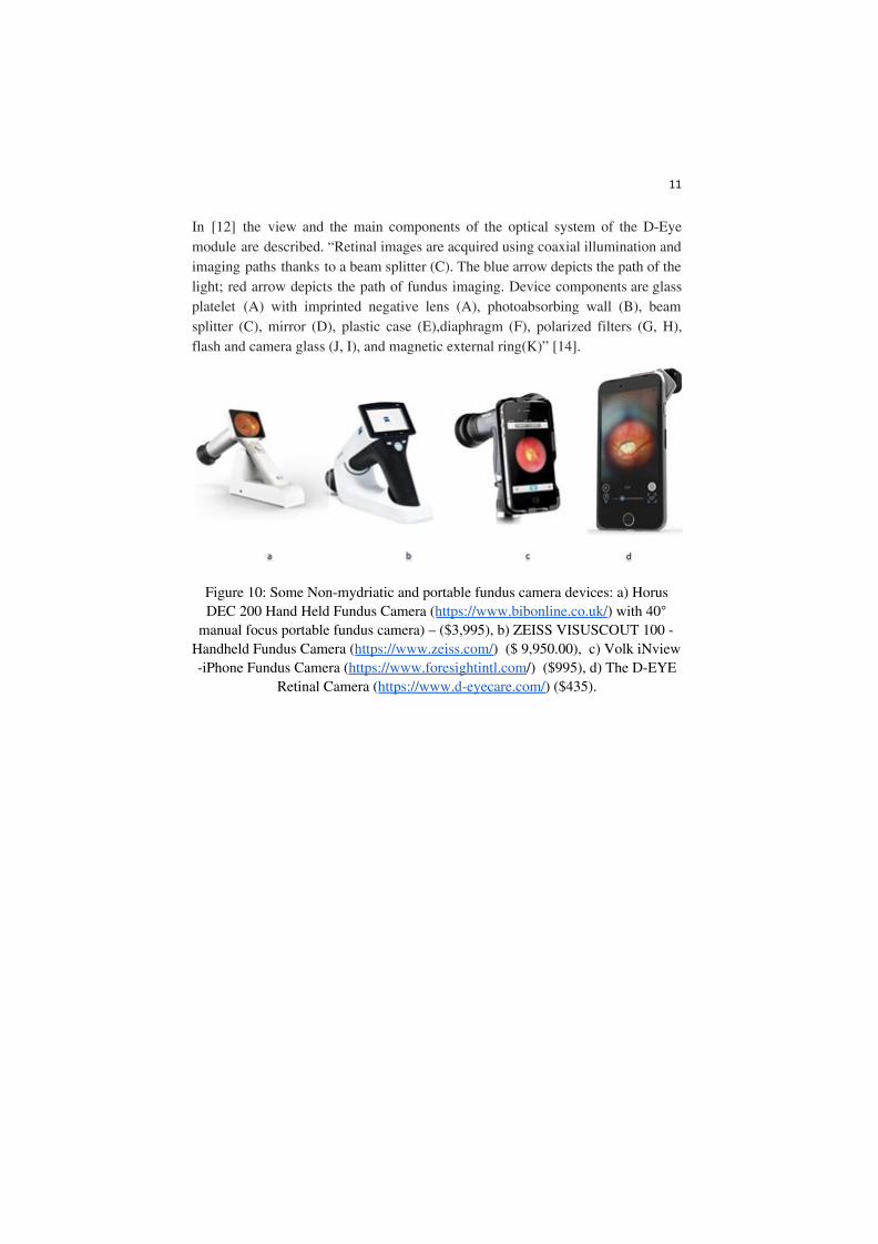
Figure 10: Some Non-mydriatic and portable fundus camera devices: a) Horus DEC 200 Hand Held Fundus Camera (https://www.bibonline.co.uk/) with 40°
manual focus portable fundus camera) – ($3,995), b) ZEISS VISUSCOUT 100 - Handheld Fundus Camera (https://www.zeiss.com/) ($ 9,950.00), c) Volk iNview -iPhone Fundus Camera (https://www.foresightintl.com/) ($995), d) The D-EYE
Retinal Camera (https://www.d-eyecare.com/) ($435).
12
Figure 11: The main components of the optical system of the D-Eye module [14].
10.3. Retinal images in Biometrics
The retina is a safe biometric characteristic, where it is very difficult if not impossible to defeat. According to the evaluation criteria for biometric modalities, the Retina is Universal (present in all individuals); The arrangement of the Retinal vessels is Unique from one individual to another, different between twins and stable during the life of individuals; Retina provides also a good Reliability and high Robustness against fraud, since it is an inner layer of the eye. In addition, it is also minimally exposed to injury, which minimizes errors of false acceptance or false rejection between individuals.
Biometric methods are always based on extracting and exploring retinal components in order to extract from them a feature set that allows person authentication. In this section, we are interested on which components and characteristics are aimed by biometric methods. One approach has consisted in extracting blood vessels in the retinal fundus images and detecting characteristic points that serve as a biometric signature in order to authenticate a person’s identity. In this approach, the person identification is based on the measure of similarity between blood vessel image generated from the Retinal fundus image as an input and reference images [15, 16].
13
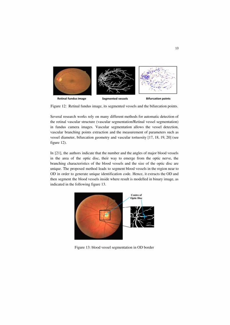
Figure 12: Retinal fundus image, its segmented vessels and the bifurcation points. Several research works rely on many different methods for automatic detection of the retinal vascular structure (vascular segmentation/Retinal vessel segmentation) in fundus camera images. Vascular segmentation allows the vessel detection, vascular branching points extraction and the measurement of parameters such as vessel diameter, bifurcation geometry and vascular tortuosity [17, 18, 19, 20] (see figure 12). In [21], the authors indicate that the number and the angles of major blood vessels in the area of the optic disc, their way to emerge from the optic nerve, the branching characteristics of the blood vessels and the size of the optic disc are unique. The proposed method leads to segment blood vessels in the region near to OD in order to generate unique identification code. Hence, it extracts the OD and then segment the blood vessels inside where result is modelled in binary image, as indicated in the following figure 13.
Figure 13: blood vessel segmentation in OD border
14
The work described in [19] aims to extract features related to the ridge endings and ridge bifurcations of the retinal vessel tree. In the first step, the level set extrinsic curvature (LSEC) is applied to the vessel tree in order to extract invariance properties which are ridges or valleys. After OD extraction, the method identified a set of points that are the ridge endings and bifurcations.
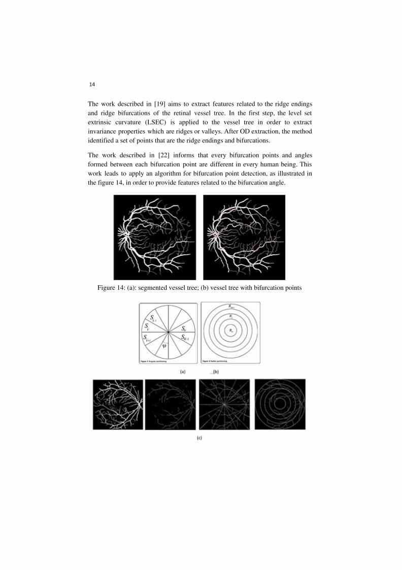
The work described in [22] informs that every bifurcation points and angles formed between each bifurcation point are different in every human being. This work leads to apply an algorithm for bifurcation point detection, as illustrated in the figure 14, in order to provide features related to the bifurcation angle.
Figure 14: (a): segmented vessel tree; (b) vessel tree with bifurcation points
15
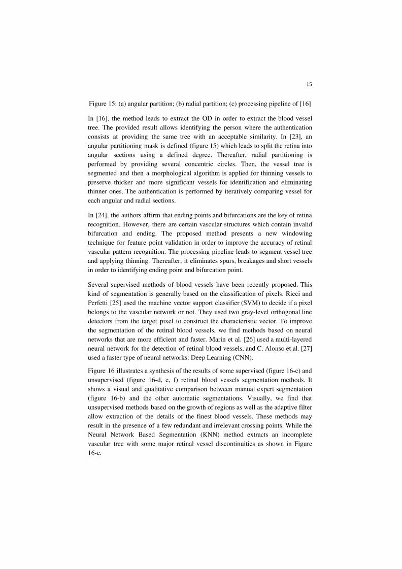
Figure 15: (a) angular partition; (b) radial partition; (c) processing pipeline of [16]
In [16], the method leads to extract the OD in order to extract the blood vessel tree. The provided result allows identifying the person where the authentication consists at providing the same tree with an acceptable similarity. In [23], an angular partitioning mask is defined (figure 15) which leads to split the retina into angular sections using a defined degree. Thereafter, radial partitioning is performed by providing several concentric circles. Then, the vessel tree is segmented and then a morphological algorithm is applied for thinning vessels to preserve thicker and more significant vessels for identification and eliminating thinner ones. The authentication is performed by iteratively comparing vessel for each angular and radial sections.
In [24], the authors affirm that ending points and bifurcations are the key of retina recognition. However, there are certain vascular structures which contain invalid bifurcation and ending. The proposed method presents a new windowing technique for feature point validation in order to improve the accuracy of retinal vascular pattern recognition. The processing pipeline leads to segment vessel tree and applying thinning. Thereafter, it eliminates spurs, breakages and short vessels in order to identifying ending point and bifurcation point.
Several supervised methods of blood vessels have been recently proposed. This kind of segmentation is generally based on the classification of pixels. Ricci and Perfetti [25] used the machine vector support classifier (SVM) to decide if a pixel belongs to the vascular network or not. They used two gray-level orthogonal line detectors from the target pixel to construct the characteristic vector. To improve the segmentation of the retinal blood vessels, we find methods based on neural networks that are more efficient and faster. Marin et al. [26] used a multi-layered neural network for the detection of retinal blood vessels, and C. Alonso et al. [27] used a faster type of neural networks: Deep Learning (CNN).
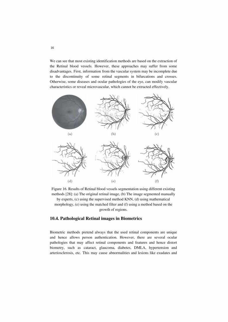
Figure 16 illustrates a synthesis of the results of some supervised (figure 16-c) and unsupervised (figure 16-d, e, f) retinal blood vessels segmentation methods. It shows a visual and qualitative comparison between manual expert segmentation (figure 16-b) and the other automatic segmentations. Visually, we find that unsupervised methods based on the growth of regions as well as the adaptive filter allow extraction of the details of the finest blood vessels. These methods may result in the presence of a few redundant and irrelevant crossing points. While the Neural Network Based Segmentation (KNN) method extracts an incomplete vascular tree with some major retinal vessel discontinuities as shown in Figure 16-c.
16
We can see that most existing identification methods are based on the extraction of the Retinal blood vessels. However, these approaches may suffer from some disadvantages. First, information from the vascular system may be incomplete due to the discontinuity of some retinal segments in bifurcations and crosses. Otherwise, some diseases and ocular pathologies of the eye, can modify vascular characteristics or reveal microvascular, which cannot be extracted effectively.
Figure 16. Results of Retinal blood vessels segmentation using different existing methods [28]: (a) The original retinal image, (b) The image segmented manually
by experts, (c) using the supervised method KNN, (d) using mathematical morphology, (e) using the matched filter and (f) using a method based on the
growth of regions.
10.4. Pathological Retinal images in Biometrics
Biometric methods pretend always that the used retinal components are unique and hence allows person authentication. However, there are several ocular pathologies that may affect retinal components and features and hence distort biometry, such as cataract, glaucoma, diabetes, DMLA, hypertension and arteriosclerosis, etc. This may cause abnormalities and lesions like exudates and
17
hemorrhages in the retina. In this section, we present several ocular pathologies that are characterized by a higher patient numbers, where disease grade retinal components used on biometry.
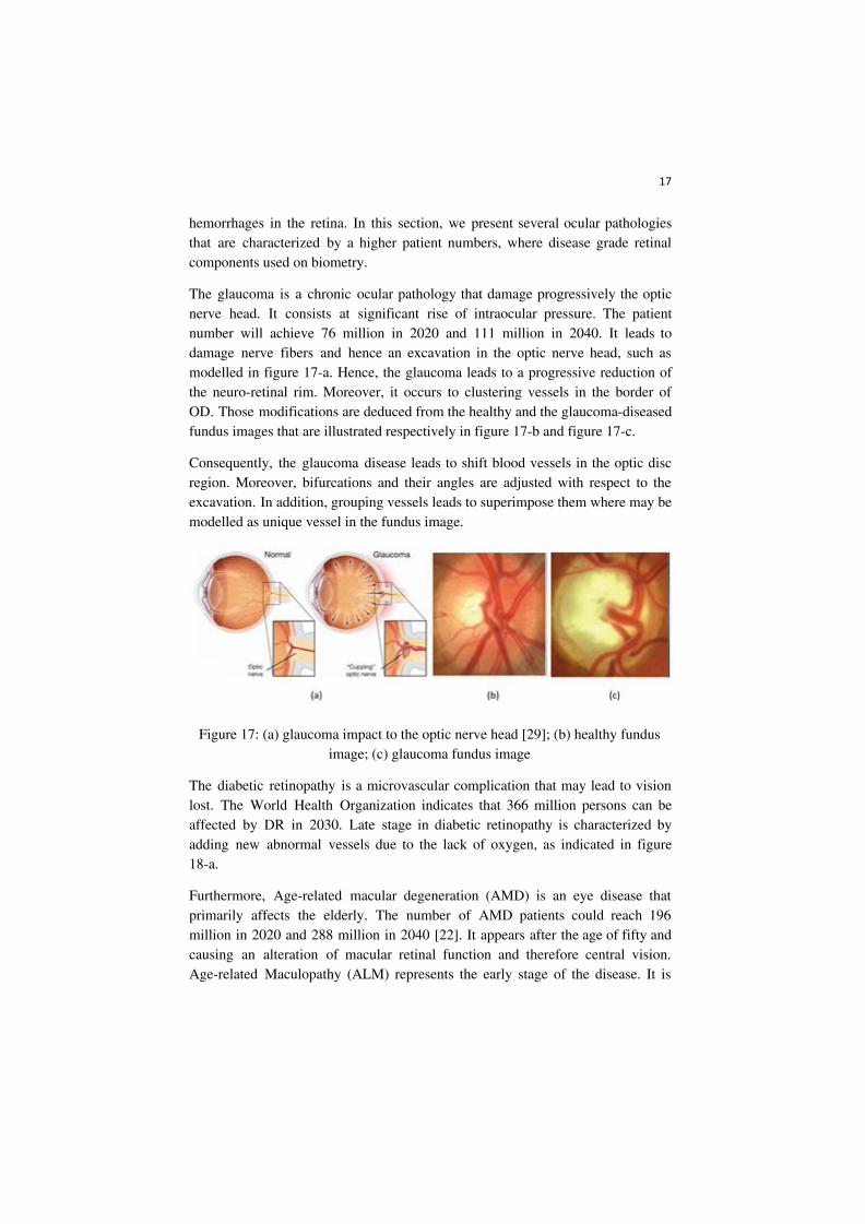
The glaucoma is a chronic ocular pathology that damage progressively the optic nerve head. It consists at significant rise of intraocular pressure. The patient number will achieve 76 million in 2020 and 111 million in 2040. It leads to damage nerve fibers and hence an excavation in the optic nerve head, such as modelled in figure 17-a. Hence, the glaucoma leads to a progressive reduction of the neuro-retinal rim. Moreover, it occurs to clustering vessels in the border of OD. Those modifications are deduced from the healthy and the glaucoma-diseased fundus images that are illustrated respectively in figure 17-b and figure 17-c.
Consequently, the glaucoma disease leads to shift blood vessels in the optic disc region. Moreover, bifurcations and their angles are adjusted with respect to the excavation. In addition, grouping vessels leads to superimpose them where may be modelled as unique vessel in the fundus image.
Figure 17: (a) glaucoma impact to the optic nerve head [29]; (b) healthy fundus image; (c) glaucoma fundus image
The diabetic retinopathy is a microvascular complication that may lead to vision lost. The World Health Organization indicates that 366 million persons can be affected by DR in 2030. Late stage in diabetic retinopathy is characterized by adding new abnormal vessels due to the lack of oxygen, as indicated in figure 18-a.
Furthermore, Age-related macular degeneration (AMD) is an eye disease that primarily affects the elderly. The number of AMD patients could reach 196 million in 2020 and 288 million in 2040 [22]. It appears after the age of fifty and causing an alteration of macular retinal function and therefore central vision. Age-related Maculopathy (ALM) represents the early stage of the disease. It is
18
characterized by the presence of alterations in the pigment epithelium of the macula or retinal complaints called exudates. At the back of the eye the exudates appear as whitish round lesions, of varying shape and size. The presence of an ALM carries a risk of developing AMD at 5 years. There are two forms of age-related macular degeneration: an atrophic form (80% of cases), and an exudative form (20% of cases) [30].
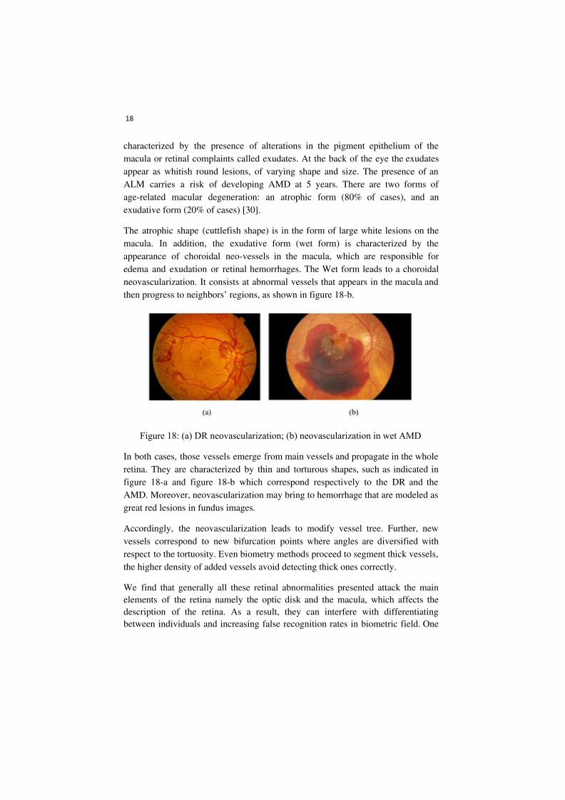
The atrophic shape (cuttlefish shape) is in the form of large white lesions on the macula. In addition, the exudative form (wet form) is characterized by the appearance of choroidal neo-vessels in the macula, which are responsible for edema and exudation or retinal hemorrhages. The Wet form leads to a choroidal neovascularization. It consists at abnormal vessels that appears in the macula and then progress to neighbors’ regions, as shown in figure 18-b.
Figure 18: (a) DR neovascularization; (b) neovascularization in wet AMD
In both cases, those vessels emerge from main vessels and propagate in the whole retina. They are characterized by thin and torturous shapes, such as indicated in figure 18-a and figure 18-b which correspond respectively to the DR and the AMD. Moreover, neovascularization may bring to hemorrhage that are modeled as great red lesions in fundus images.
Accordingly, the neovascularization leads to modify vessel tree. Further, new vessels correspond to new bifurcation points where angles are diversified with respect to the tortuosity. Even biometry methods proceed to segment thick vessels, the higher density of added vessels avoid detecting thick ones correctly.
We find that generally all these retinal abnormalities presented attack the main elements of the retina namely the optic disk and the macula, which affects the description of the retina. As a result, they can interfere with differentiating between individuals and increasing false recognition rates in biometric field. One
19
solution to overcome these problems of pathological retinal images may be to find the most stable region, even where retinal pathologies appears.
10.5. Conclusion
The retina is the sensory layer of the eye that allows vision. It is captured using a biometric scanner that uses a visible beam of light to trace a circular path on the retina to the back of the eye. The acquisition systems have been improved over time. We have presented in section 2, an overview of existing Retinal imaging and capture devices.
Based on described works in section 3, most biometry method based on retinal images proceed to segment OD and blood vessels. the vessel tree is considered as unique component which is used to authentication [21, 16, 23]. Other works extract bifurcations and ending points from blood vessels which are considered as personal unique features [19, 24]. To avoid noising and difference between segmentation methods, several methods proceed to thinning vessels before extracting biometry features, in order to preserve only main vessels [24, 23]. Others works aim to filter bifurcation and ending points to ensure a performant identification process [24].
These Biometric methods pretend always that the used retinal components are unique and hence allows person authentication. However, there are several ocular pathologies that may affect retinal components and features and hence distort biometry. In section 4, we have presented several ocular pathologies that are characterized by a higher patient numbers, where disease grade retinal components used on biometry. The challenge here is to ensure efficient biometrics regardless of ocular pathology. In this context, Retinal Imaging plays also a key role including the diagnosis and treatment of the ocular diseases [1].
10.6. References
[1] R Michael D. Abràmoff, Mona K. Garvin, Milan Sonka. Retinal Imaging and Image Analysis, IEEE Rev Biomed Eng. 2010 January 1; 3: 169–208. doi:10.1109/RBME.2010.2084567.
[2] A. K. Jain, R. Bolle, S. Pankanti. Biometrics: personal identification in networked society, Springer Science & Business Media, 1999. Simon and Goldstein [6] discovered that the blood vessels (BVs) in the retina are unique to each individual.
[3] C. Simon and I. Goldstein, “A New Scientific Method of Identification,” New York State Journal of Medicine, vol. 35, pp. 901906, 1935

20
[4] Manivannan A., Kirkpatrick J. N. P., Sharp P.F., Forrester J. V. Novel approach towards coulour imaging using scanning laser ophthalmoscope. Br. J. Ophthalmol. 82(4), 342-345 (1998). 10. 1135/bjo. 82.4.342.
[5] Hermann B, Fernandez EJ, Unterhubner A, Sattmann H, Fercher AF, Drexler W, Prieto PM, Artal P. Adaptative-optics ultrahigh-resolution optical tomography. Opt Let 2004: 29:2142-2144.
[6] DelHoog, E., Schwiegerling, J. Fundus camera systems: a comparative analysis. Appl. Opt. 48(2): 221-228 (2009).
[7] V. J. Srinivasan, R. Huber, I. Gorczynska, and J. G. Fujimoto. High-speed, high-resolution optical coherence tomography retinal imaging with a frequency-swep laser at 850 nm. February 15, 2007 / Vol. 32, No. 4 / OPTICS LETTERS.
[8] Chen Ma, Dewen Cheng, Chen Xu, Yongtian Wang. Design, simulation and experimental analysis of an anti-stray-light illumination system of fundus camera. Proceedings of SPIE - The International Society for Optical Engineering · November 2014
[9] Soliman, AZ, Silva, PS, Aiello, LP & Sun, JK 2012, ‘Ultra-wide field retinal imaging in detection, classification, and management of diabetic retinopathy’, Seminars in Ophthalmology, vol. 27, no. 5–6, pp. 221–227.
[10] Zhongwei Zhi, William O. Cepurna, Elaine C. Johnson, John C. Morrison, Ruikang K. Wang. Impact of intraocular pressure on changes of blood flow in the retina, choroid, and optic nerve head in rats investigated by optical microangiography/ Biomedical Optics Express 3(9):2220-33 · September 2012.
[11] Rui Bernardes, Pedro Serranho, Conceição Lobo. Digital Ocular Fundus Imaging: A Review Ophthalmologica 2011; 226:161–181, DOI: 10.1159/000329597. Published online: September 22, 2011.
[12] Nishtha Panwar, Jiaying Lee, Tjin Swee Chuan, Stephen Teoh, Philemon Huang, Pearse A. Keane, Ashutosh Richhariya, Tock Han Lim, Rupesh Agrawal. Fundus Photography in the 21st Century—A Review of Recent Technological Advances and Their Implications for Worldwide Healthcare. Telemedicine and e-Health · August 2015. DOI: 10.1089/tmj.2015.0068
[13] Andrea Russo, Luisa Delcassi, Francesco Morescalchi, Francesco Semeraro, Ciro Costagliola. A Novel Device to Exploit the Smartphone Camera for Fundus Photography. Journal of Ophthalmology Volume 2015, Article ID 823139, 5 pages http://dx.doi.org/10.1155/2015/823139.

21
[14] Andrea Russo, Francesco Morescalchi, Ciro Costagliola, Luisa Delcassi, and Francesco Semeraro. A Novel Device to Exploit the Smartphone Camera for Fundus Photography in Journal of Ophthalmology 2015:1-5 · July 2015.
[15] Fraz MM, Remagnino P, Hoppe A, Uyyanonvara B, Rudnicka AR, Owen CG, et al. Blood vessel segmentation methodologies in retinal images: a survey. Computer Methods Programs Biomed 2012; 108:407–33.
[16] Keisuke Fukuta, Toshiaki Nakagawa, Yoshinori Hayashi, Yuji Hatanaka, Takeshi Hara, Hiroshi Fujita. Personal Identification Based on Blood Vessels of Retinal Fundus Images. Medical Imaging 2008, Image Processing, Proc. of SPIE Vol. 6914, 69141V, (2008), 1605-7422/08/$18 · doi: 10.1117/12.769330.
[17] Wang L, Wong TY, Sharrett AR, Klein R, Folsom AR, Jerosch-Herold M. Relationship between retinal arteriolar narrowing and myocardial perfusion: multi-ethnic study of atherosclerosis. Hypertension 2008; 51:119–26. doi: 10.1161/HYPERTENSIONAHA.107.09834
[18] Amin Dehghani, Zeinab Ghassabi, Hamid Abrishami Moghddam, Mohammad Shahram Moin. Human recognition based on retinal images and using new similarity function. EURASIP Journal on Image and Video Processing 2013, 2013:58.
[19] M. ORTEGA, C. MARINO, M.G. PENEDO, M.BLANCO, F.GONZALEZ. Biometric authentication using digital retinal images. Proceedings of the 5th WSEAS International Conference on Applied Computer Science, Hangzhou, China, April 16-18, 2006 (pp422-427).
[20] Modarresi M, Oveisi IS, Janbozorgi M. Retinal Identification using Shearlets Feature Extraction. Austin Biometrics and Biostatistics. December 29, 2017. Austin Biom and Biostat 4(1): id1035.
[21] Anushikha Singh, Malay Kishore Dutta, Dilip Kumar Sharma, « Unique identification code for medical fundus images using blood vessel pattern for tele-ophthalmology applications », computer methods and programs in biomedicine, vol: 135, 2016, pages: 161-175.
[22] Nilanjana Dutta Roy, Arindam Biswas, « Detection of bifurcation angles in a retinal fundus image », 2015 Eighth International Conference on Advances in Pattern Recognition (ICAPR), 4-7 Jan. 2015.
[23] Wafa Barkhoda1*, Fardin Akhlaqian1, Mehran Deljavan Amiri1 and Mohammad Sadeq Nouroozzadeh, « Retina identification based on the pattern of

22
blood vessels using fuzzy logic », EURASIP Journal on Advances in Signal Processing 2011, 2011 :113.
[24] Joddat Fatima†, Adeel M. Syed‡ and M. Usman Akram, « Feature Point Validation for Improved Retina Recognition », 2013 IEEE Workshop on Biometric Measurements and Systems for Security and Medical Applications, Naples, Italy, 9-9 Sept. 2013.
[25] E. Ricci and R. Perfetti. Retinal Blood Vessel Segmentation Using Line Operators and Support Vector Classification. IEEE Transactions on Medical imaging, vol. 26, pp. 1357-1365, 2007.
[26] D. Marin, A. Aquino, M. Emilio Gegndez-Arias and J. Manuel Bravo. A new supervised method for blood vessel segmentation in retinal images by using gray-level and moment invariants-based features. Medical Imaging, IEEE Transactions on, vol.30, no.1, pp. 146-158, 2011.
[27] C. Alonso-Montes, D. L. Vilarino and M. G. Penedo. CNN-based Automatic Retinal Vascular Tree Extraction. IEEE, pp 61-64, 2010.
[28] F. Zana and J. Klein. Segmentation of vessel-like patterns using mathematical morphology and curvature evaluation. IEEE Trans. Image Processing 10, pp.1010-1019, 2001.
[29] Umarani Balakrishnan, « NDC-IVM: An Automatic Segmentation of Optic Disc and Cup Region from Medical Images for Glaucoma Detection », Journal of Innovative Optical Health Sciences, Vol. 10, No. 03, 1750007, 2017.
[30] http ://www.creteilophtalmo.fr/dmla/.