Embed Size (px)
DESCRIPTION
practical
Citation preview
Electrical Machines-I Lab
S.No. Name of the Experiment Page.No
1 MAGNETIZATION CHARACTERISTICS OF A DC SHUNT GENERATOR
2
2 LOAD TEST ON DC SHUNT GENERATOR 6
3 LOAD TEST ON DC COMPOUND GENERATOR 10
4 BRAKE TEST ON DC SHUNT MOTOR 14
5 SWINBURNE’S TEST ON A DC SHUNT MACHINE 18
6 LOAD TEST ON DC SERIES GENERATOR 22
7 HOPKINSON’S TEST ON DC SHUNT MACHINE 26
8 FIELDS TEST ON DC SERIES MACHINES 31
9 SPEED CONTROL OF DC SHUNT MOTOR 36
10 SEPERATION OF LOSSES IN DC SHUNT MOTOR 41
11 BRAKE TEST ON DC COMPOUND MOTOR 45
12 RETARDATION TEST ON DC SHUNT MOTOR 50
EEE Department,GIST-Jaggayyapet Page 1
Electrical Machines-I Lab
1.MAGNETISATION CHARACTERISTICS OF A D.C SHUNT GENERATOR.
AIM:
To find the magnetization characteristics of a D.C shunt generator.
To find the critical field resistance and critical speed.
NAMEPLATE DETAILS:
MOTOR GENERATOR
Power3.7kw 3.7kw
Wound Shunt ShuntArmature voltage
220V. 220V.
Armature current
20 A 17A
Excitation 220V, 0.9A 220V, 0.9ASpeed 1500. 1500.
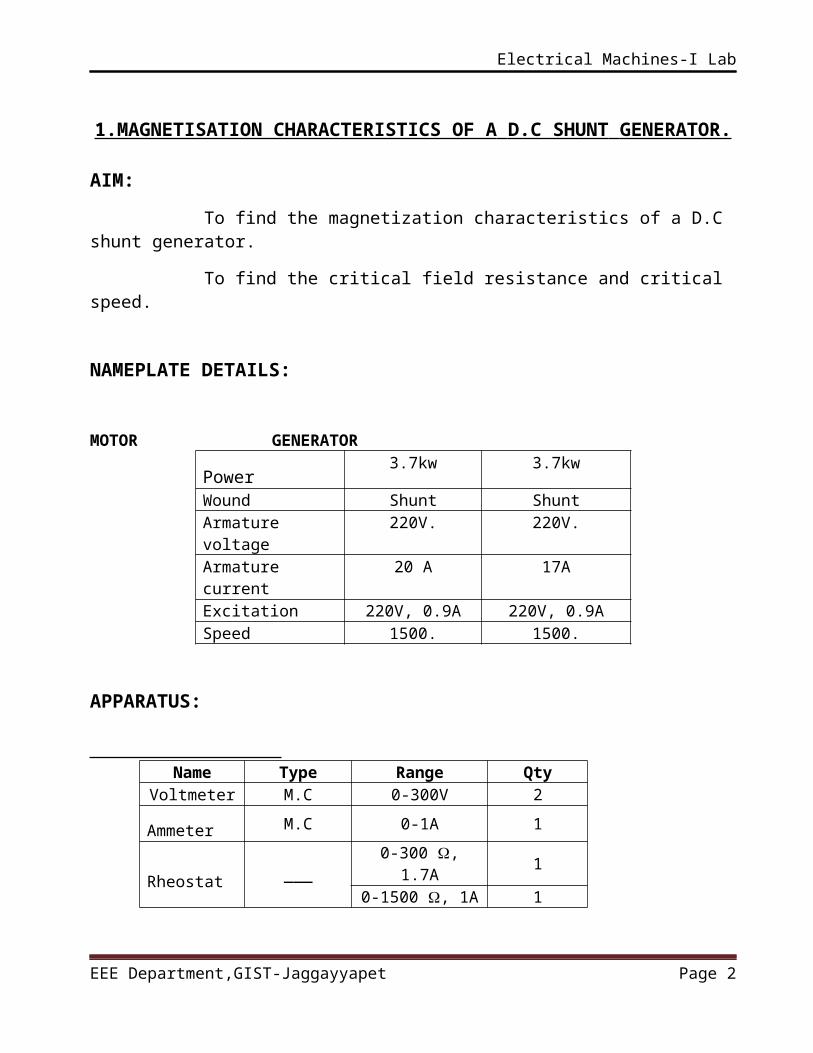
APPARATUS:
Name Type Range Qty
Voltmeter M.C 0-300V 2
Ammeter M.C 0-1A 1
Rheostat___
0-300 , 1.7A 10-1500 , 1A 1
Tachometer
--- 1
EEE Department,GIST-Jaggayyapet Page 2
Electrical Machines-I Lab
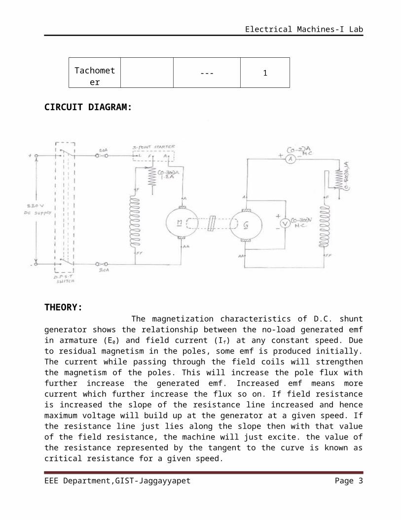
CIRCUIT DIAGRAM:
THEORY: The magnetization characteristics of D.C. shunt generator shows the relationship between the no-load generated emf in armature (E0) and field current (If) at any constant speed. Due to residual magnetism in the poles, some emf is produced initially. The current while passing through the field coils will strengthen the magnetism of the poles. This will increase the pole flux with further increase the generated emf. Increased emf means more current which further increase the flux so on. If field resistance is increased the slope of the resistance line increased and hence maximum voltage will build up at the generator at a given speed. If the resistance line just lies along the slope then with that value of the field resistance, the machine will just excite. the value of the resistance represented by the tangent to the curve is known as critical resistance for a given speed. PROCEDURE:
1. Connect the circuit as per the circuit diagram.2. Keep the motor field rheostat at minimum position and generator
field rheostat at maximum position.3. Start the motor with the help of 3- point starter and adjust the
motor field rheostat till the motor reaches to its rated speed.4. Gradually increases the field current of generator by minimize the
generator field rheostat resistance.
EEE Department,GIST-Jaggayyapet Page 3
Electrical Machines-I Lab
5. Note the terminal voltage (V) of generator at various field currents (If). Till the generator attains its rated voltage.
6. The relationship between no load voltage (V) and field current (I f) gives the open circuit characteristics (OCC).
7. Draw the graph (OCC) between terminal voltage (V) and field current (If) to find out the critical field resistance and critical sped.
TABULATION:
S.noField current
If(A)Voltage
(V)
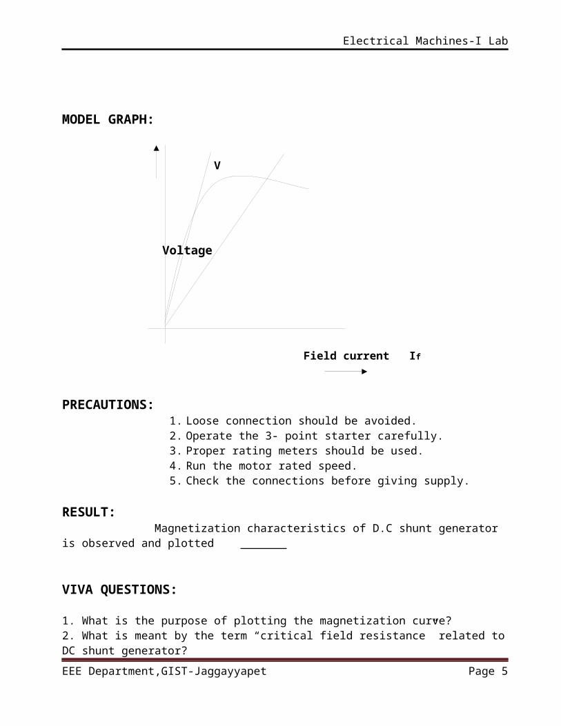
MODEL GRAPH:
V
Voltage
Field current If
EEE Department,GIST-Jaggayyapet Page 4
Electrical Machines-I Lab
PRECAUTIONS: 1. Loose connection should be avoided.2. Operate the 3- point starter carefully.3. Proper rating meters should be used. 4. Run the motor rated speed. 5. Check the connections before giving supply.
RESULT: Magnetization characteristics of D.C shunt generator is observed and plotted
VIVA QUESTIONS:
1. What is the purpose of plotting the magnetization curve?2. What is meant by the term “critical field resistance” related to DC shunt generator?3. What are the conditions to be fulfilled for the shunt generator to build up voltage?4. Why does saturation curve starts from some value higher than zero?5. What is the type of voltage induced in the armature of a DC generator?
EEE Department,GIST-Jaggayyapet Page 5
Electrical Machines-I Lab
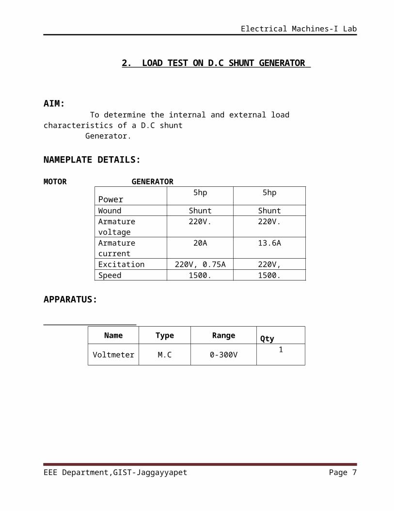
2. LOAD TEST ON D.C SHUNT GENERATOR
AIM: To determine the internal and external load characteristics of a D.C shunt Generator.
NAMEPLATE DETAILS: MOTOR GENERATOR
Power5hp 5hp
Wound Shunt ShuntArmature voltage
220V. 220V.
Armature current
20A 13.6A
Excitation 220V, 0.75A 220V,Speed 1500. 1500.
APPARATUS:
Name Type Range Qty
Voltmeter M.C 0-300V1
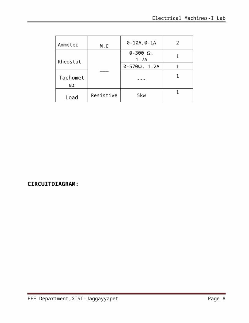
Ammeter M.C0-10A,0-1A 2
Rheostat___
0-300 , 1.7A 10-570, 1.2A 1
Tachometer
---1
Load Resistive 5kw1
EEE Department,GIST-Jaggayyapet Page 6
Electrical Machines-I Lab
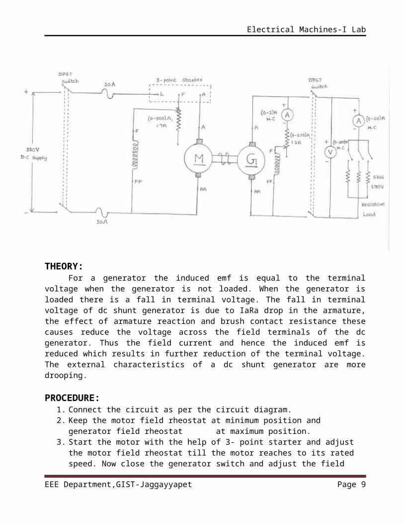
CIRCUITDIAGRAM:
THEORY: For a generator the induced emf is equal to the terminal voltage when the
generator is not loaded. When the generator is loaded there is a fall in terminal voltage. The fall in terminal voltage of dc shunt generator is due to IaRa drop in the armature, the effect of armature reaction and brush contact resistance these causes reduce the voltage across the field terminals of the dc generator. Thus the field current and hence the induced emf is reduced which results in further reduction of the terminal voltage. The external characteristics of a dc shunt generator are more drooping. PROCEDURE:
1. Connect the circuit as per the circuit diagram.2. Keep the motor field rheostat at minimum position and generator field
rheostat at maximum position.3. Start the motor with the help of 3- point starter and adjust the motor field
rheostat till the motor reaches to its rated speed. Now close the generator switch and adjust the field rheostat of the generator till it reaches to its rated voltage.
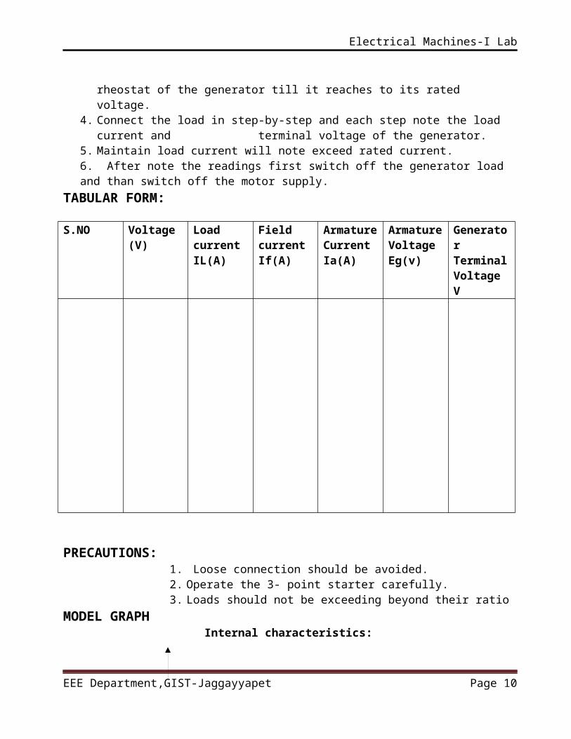
4. Connect the load in step-by-step and each step note the load current and terminal voltage of the generator.
EEE Department,GIST-Jaggayyapet Page 7
Electrical Machines-I Lab
5. Maintain load current will note exceed rated current.6. After note the readings first switch off the generator load and than switch off the motor supply.
TABULAR FORM:
S.NO Voltage (V)
Load current IL(A)
Field currentIf(A)
ArmatureCurrentIa(A)
ArmatureVoltageEg(v)
Generator Terminal Voltage V
PRECAUTIONS: 1. Loose connection should be avoided.2. Operate the 3- point starter carefully.3. Loads should not be exceeding beyond their ratio
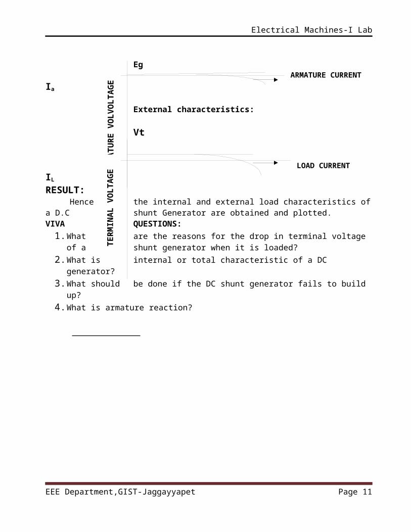
MODEL GRAPH Internal characteristics: Eg
ARMATURE CURRENT Ia
External characteristics:
Vt
EEE Department,GIST-Jaggayyapet Page 8
AR
MA
TU
RE
VO
LV
OL
TA
GE
TE
RM
INA
L V
OL
TA
GE
Electrical Machines-I Lab
LOAD CURRENT IL
RESULT: Hence the internal and external load characteristics of a D.C shunt
Generator are obtained and plotted. VIVA QUESTIONS:
1. What are the reasons for the drop in terminal voltage of a shunt generator when it is loaded?
2. What is internal or total characteristic of a DC generator?3. What should be done if the DC shunt generator fails to build up?4. What is armature reaction?
EEE Department,GIST-Jaggayyapet Page 9
Electrical Machines-I Lab
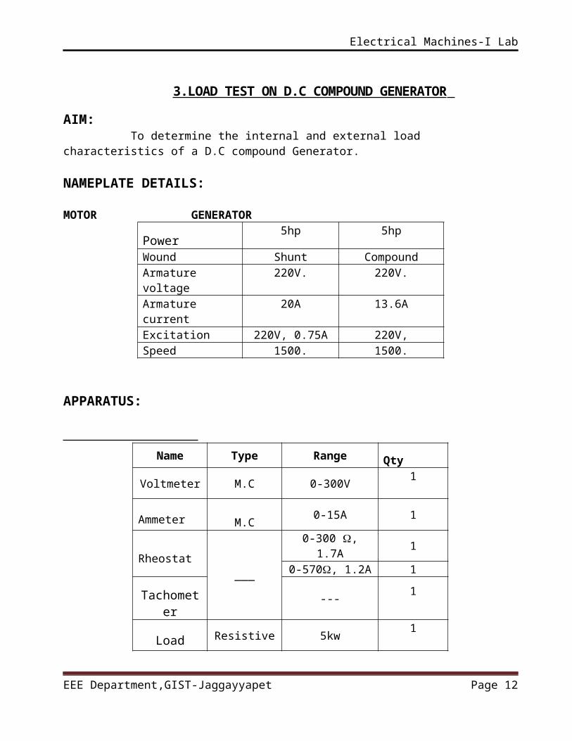
3.LOAD TEST ON D.C COMPOUND GENERATOR
AIM: To determine the internal and external load characteristics of a D.C compound Generator.
NAMEPLATE DETAILS: MOTOR GENERATOR
Power5hp 5hp
Wound Shunt CompoundArmature voltage
220V. 220V.
Armature current
20A 13.6A
Excitation 220V, 0.75A 220V,Speed 1500. 1500.
APPARATUS:
Name Type Range Qty
Voltmeter M.C 0-300V1
Ammeter M.C0-15A 1
Rheostat___
0-300 , 1.7A 10-570, 1.2A 1
Tachometer
---1
Load Resistive 5kw1
EEE Department,GIST-Jaggayyapet Page 10
Electrical Machines-I Lab
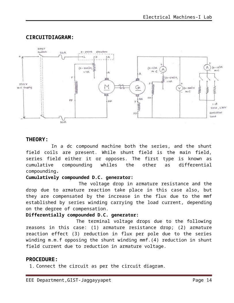
CIRCUITDIAGRAM:
THEORY: In a dc compound machine both the series, and the shunt field coils are present. While shunt field is the main field, series field either it or opposes. The first type is known as cumulative compounding whiles the other as differential compounding.Cumulatively compounded D.C. generator: The voltage drop in armature resistance and the drop due to armature reaction take place in this case also, but they are compensated by the increase in the flux due to the mmf established by series winding carrying the load current, depending on the degree of compensation.Differentially compounded D.C. generator: The terminal voltage drops due to the following reasons in this case: (1) armature resistance drop; (2) armature reaction effect (3) reduction in flux per pole due to the series winding m.m.f opposing the shunt winding mmf.(4) reduction in shunt field current due to reduction in armature voltage.
PROCEDURE:1. Connect the circuit as per the circuit diagram.2. Keep the motor field rheostat at minimum position and generator field
rheostat at maximum position.3. Start the rheostat till the motor reaches to its rated speed. Motor with the
help of 3- point starter and adjust the motor field4. Now adjust the field rheostat of the generator till it reaches to its rated
voltage.5. Connect the load in step-by-step and each step note the load current (IL),
field current (If) and terminal voltage (V) of the shunt generator.6. Maintain load current will note exceed rated current.
EEE Department,GIST-Jaggayyapet Page 11
Electrical Machines-I Lab
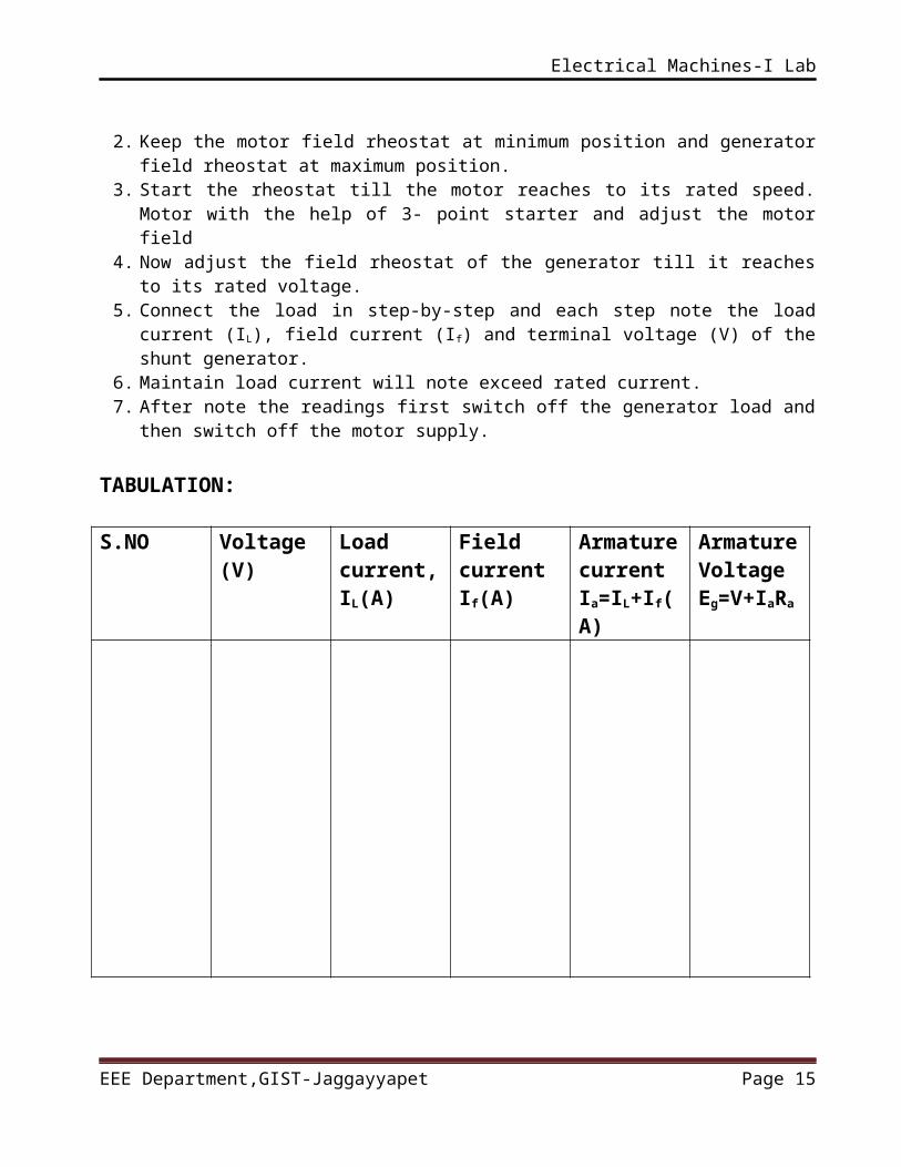
7. After note the readings first switch off the generator load and then switch off the motor supply.
TABULATION:
S.NO Voltage (V) Load current, IL(A)
Field current If(A)
Armature currentIa=IL+If(A)
ArmatureVoltageEg=V+IaRa
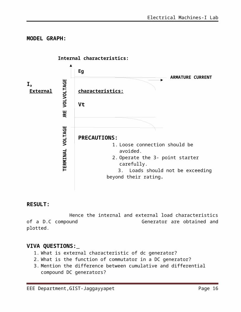
MODEL GRAPH:
Internal characteristics: Eg
ARMATURE CURRENT Ia
External characteristics:
Vt
PRECAUTIONS: 1. Loose connection should be avoided.2. Operate the 3- point starter carefully.
EEE Department,GIST-Jaggayyapet Page 12
AR
MA
TU
RE
V
OL
VO
LT
AG
ET
ER
MIN
AL
VO
LT
AG
E

Electrical Machines-I Lab
3. Loads should not be exceeding beyond their rating.
RESULT:
Hence the internal and external load characteristics of a D.C compound Generator are obtained and plotted.
VIVA QUESTIONS:
1. What is external characteristic of dc generator?2. What is the function of commutator in a DC generator? 3. Mention the difference between cumulative and differential compound DC
generators?4. Can you measure the “induced voltage” under load condition for a DC
generator? Why?5. Do you require a starter for a DC motor under the running condition, why?
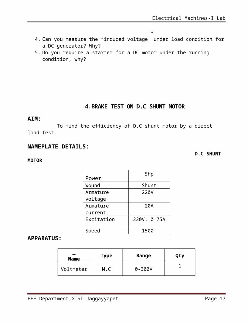
4.BRAKE TEST ON D.C SHUNT MOTOR
AIM: To find the efficiency of D.C shunt motor by a direct load test.
NAMEPLATE DETAILS: D.C SHUNT MOTOR
Power5hp
Wound ShuntArmature voltage
220V.
Armature current
20A
Excitation 220V, 0.75A
Speed 1500.APPARATUS:
Type Range Qty
EEE Department,GIST-Jaggayyapet Page 13
Electrical Machines-I Lab
Name
Voltmeter M.C 0-300V1
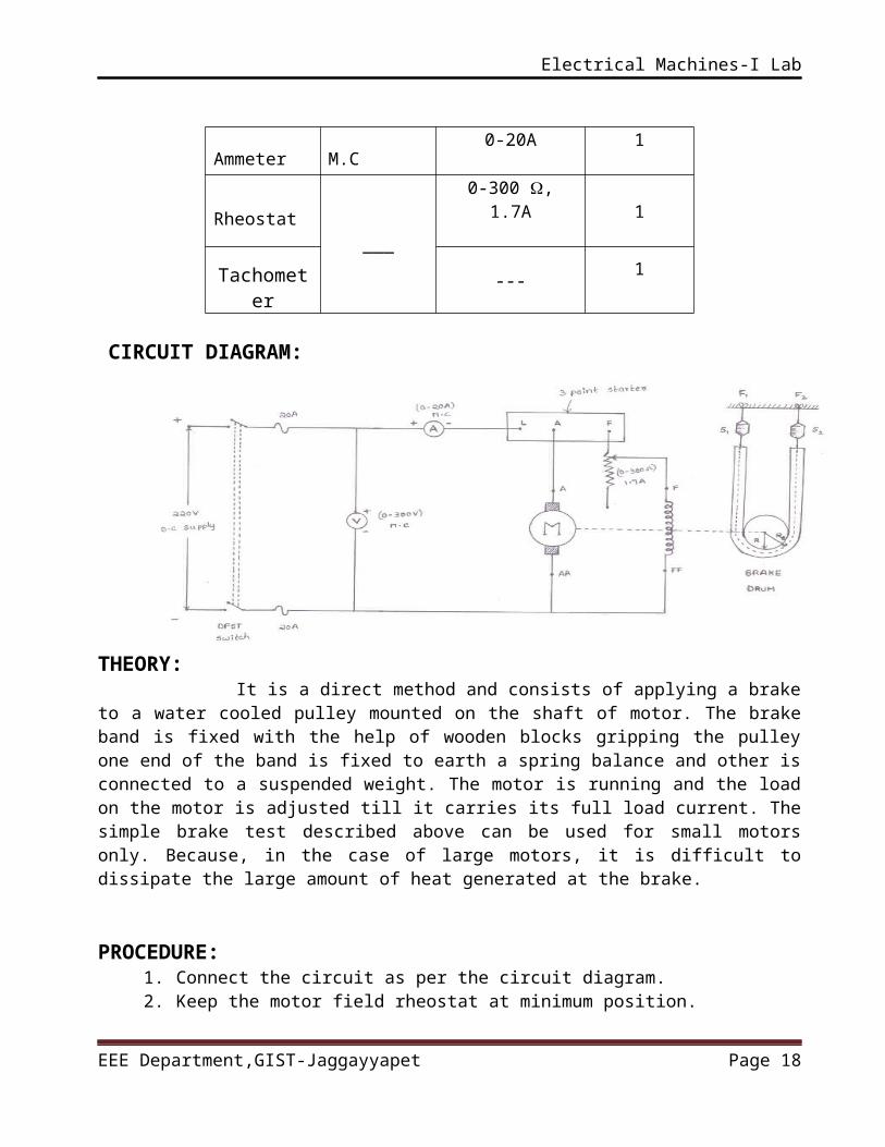
Ammeter M.C0-20A 1
Rheostat___
0-300 , 1.7A1
Tachometer
---1
CIRCUIT DIAGRAM:
THEORY: It is a direct method and consists of applying a brake to a water cooled pulley mounted on the shaft of motor. The brake band is fixed with the help of wooden blocks gripping the pulley one end of the band is fixed to earth a spring balance and other is connected to a suspended weight. The motor is running and the load on the motor is adjusted till it carries its full load current. The simple brake test described above can be used for small motors only. Because, in the case of large motors, it is difficult to dissipate the large amount of heat generated at the brake.
PROCEDURE:1. Connect the circuit as per the circuit diagram.2. Keep the motor field rheostat at minimum position.3. Start the motor with the help of 3- point starter and Adjust the motor
field rheostat till the motor reaches To its rated speed.4. Now gradually apply the mechanical load by tightening the Belt over the
shaft.
EEE Department,GIST-Jaggayyapet Page 14
Electrical Machines-I Lab
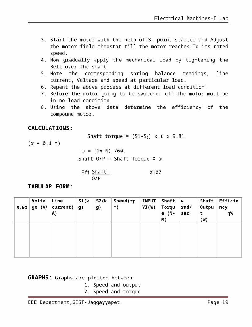
5. Note the corresponding spring balance readings, line current, Voltage and speed at particular load.
6. Repent the above process at different load condition.7. Before the motor going to be switched off the motor must be in no load
condition.8. Using the above data determine the efficiency of the compound motor.
CALCULATIONS: Shaft torque = (S1-S2) x r x 9.81 (r = 0.1 m) ω = (2 N) /60. Shaft O/P = Shaft Torque X ω
Efficiency= = X100
TABULAR FORM:
S.NO
Voltage (V)
Line current(A)
S1(kg) S2(kg) Speed(rpm) INPUTVI(W)
ShaftTorque (N-M)
ωrad/sec
Shaft Output (W)
Efficiency η%
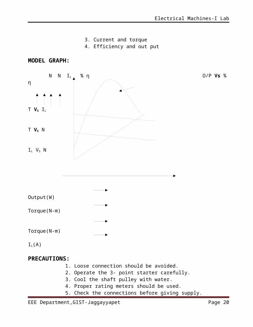
GRAPHS: Graphs are plotted between 1. Speed and output 2. Speed and torque 3. Current and torque 4. Efficiency and out put MODEL GRAPH:
N N IL % η O/P Vs % η
T VS IL T VS N
IL VS N
EEE Department,GIST-Jaggayyapet Page 15
Shaft O/P Power
Electrical Machines-I Lab
Output(W) Torque(N-m) Torque(N-m) IL(A) PRECAUTIONS:
1. Loose connection should be avoided.2. Operate the 3- point starter carefully.3. Cool the shaft pulley with water.4. Proper rating meters should be used.5. Check the connections before giving supply.
RESULT:Hence the efficiency of the D.C shunt motor at various load conditions
are calculated and plotted.
VIVA QUESTIONS: 1. What is back EMF?2. How can the direction of rotation be reversed in a DC motor?3. Do you require a starter for a DC motor under the running condition, why?4. Why does the speed fall slightly when the DC shunt motor is loaded?5. What happens if the field circuit of a DC motor is opened under running condition?
EEE Department,GIST-Jaggayyapet Page 16
Electrical Machines-I Lab
5.SWINBURNE’S TEST ON D.C SHUNT MACHINE
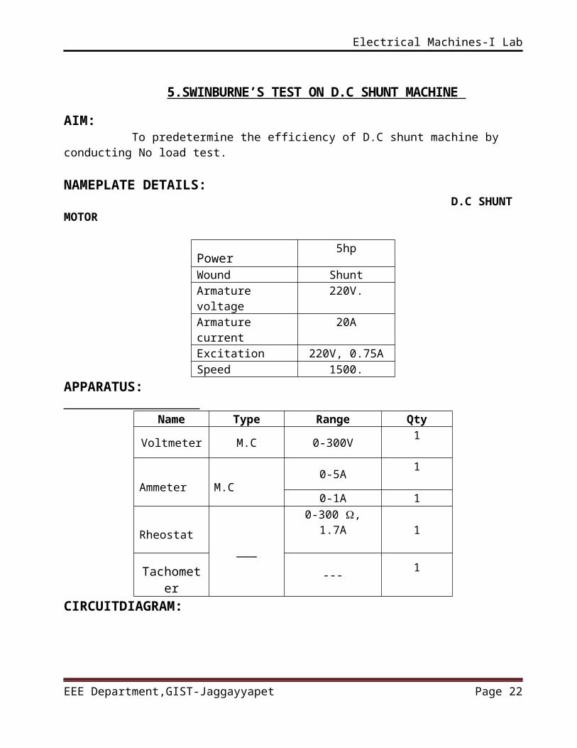
AIM: To predetermine the efficiency of D.C shunt machine by conducting No load test.
NAMEPLATE DETAILS: D.C SHUNT MOTOR
Power5hp
Wound ShuntArmature voltage
220V.
Armature current
20A
Excitation 220V, 0.75ASpeed 1500.
APPARATUS:
Name Type Range Qty
Voltmeter M.C 0-300V1
Ammeter M.C0-5A
1
0-1A 1
Rheostat___
0-300 , 1.7A1
Tachometer
---1
CIRCUITDIAGRAM:
EEE Department,GIST-Jaggayyapet Page 17
Electrical Machines-I Lab
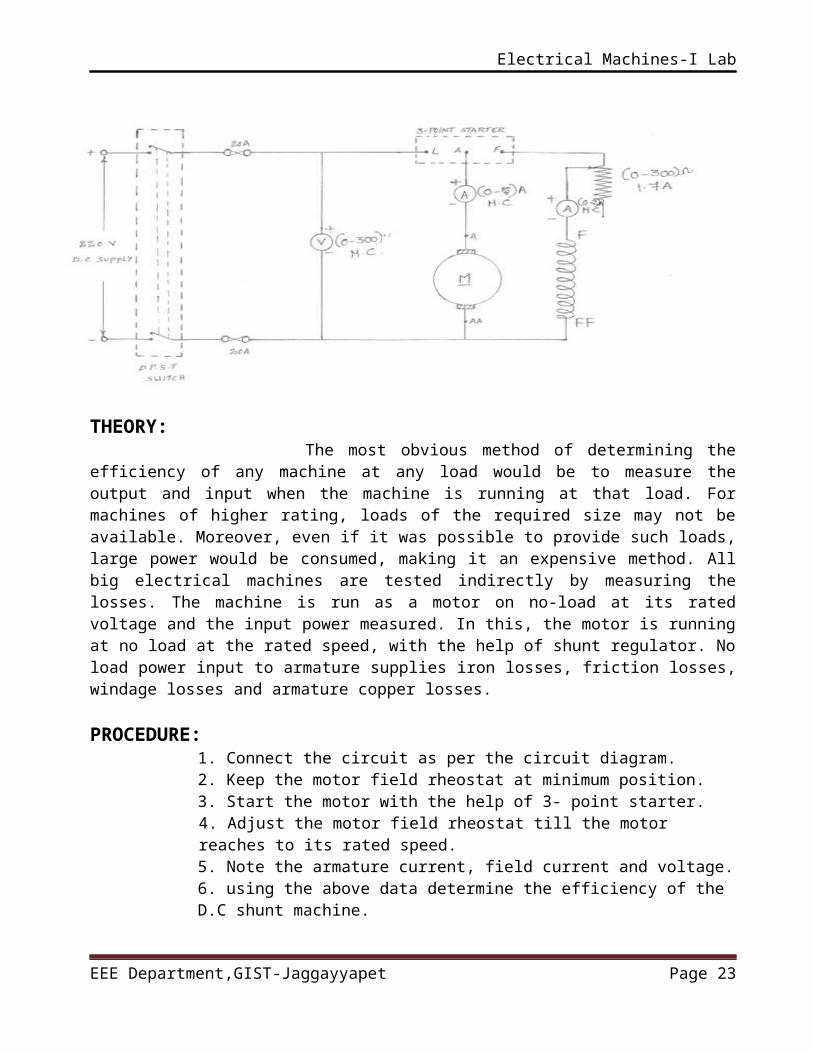
THEORY: The most obvious method of determining the efficiency of any machine at any load would be to measure the output and input when the machine is running at that load. For machines of higher rating, loads of the required size may not be available. Moreover, even if it was possible to provide such loads, large power would be consumed, making it an expensive method. All big electrical machines are tested indirectly by measuring the losses. The machine is run as a motor on no-load at its rated voltage and the input power measured. In this, the motor is running at no load at the rated speed, with the help of shunt regulator. No load power input to armature supplies iron losses, friction losses, windage losses and armature copper losses.
PROCEDURE:1. Connect the circuit as per the circuit diagram.2. Keep the motor field rheostat at minimum position.3. Start the motor with the help of 3- point starter.4. Adjust the motor field rheostat till the motor reaches to its rated speed.5. Note the armature current, field current and voltage. 6. using the above data determine the efficiency of the D.C shunt machine.
TABULAR FORM:
Voltage(V)
Armature current
(Ia)
Field current(If)
Load current(IL0 = Ia + If)
CALCULATIONS: MOTOR:Ia=IL-Ish
IL0=Ia0+Ish
Constant losses Wc=VIL0-Ia02Ra
Armature cupper losses Wcu= Ia2 Ra
Total losses in the motor Wt =(Wc+ Ia2 Ra)
Efficiency =output/input =input-losses/inputGENERATOR:Ia=IL+Ish
IL0=Ia0+Ish
Constant losses Wc=VIL0-Ia02Ra
Armature cupper losses Wcu= Ia2 Ra
EEE Department,GIST-Jaggayyapet Page 18
Electrical Machines-I Lab
Total losses in the motor Wt =(Wc+ Ia2 Ra)
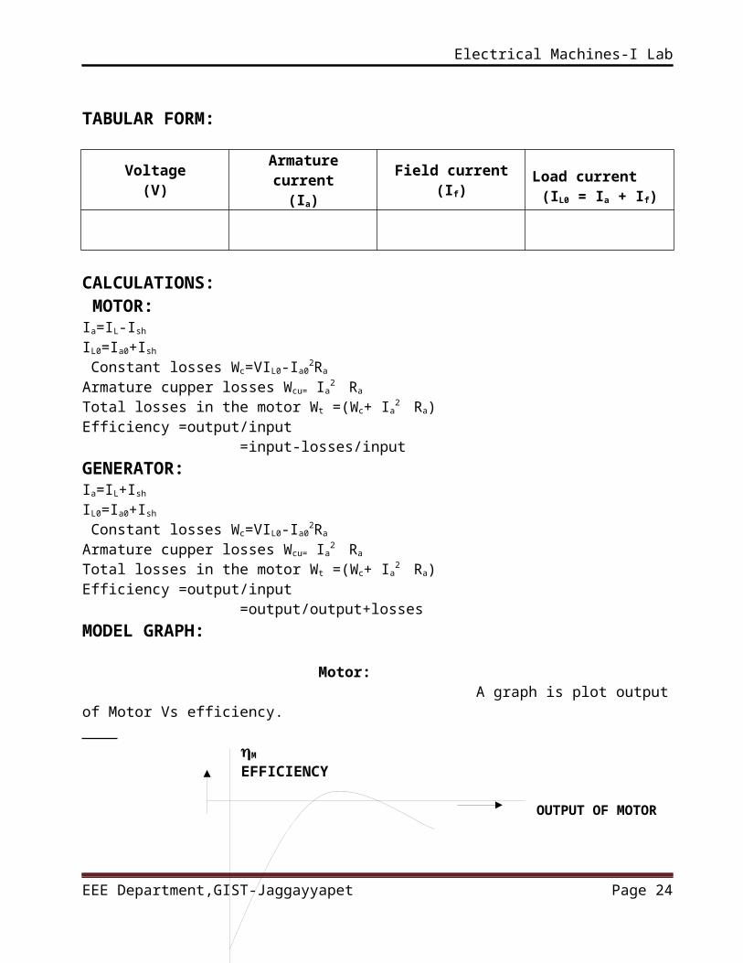
Efficiency =output/input =output/output+lossesMODEL GRAPH: Motor: A graph is plot output of Motor Vs efficiency. M
EFFICIENCY
OUTPUT OF MOTOR
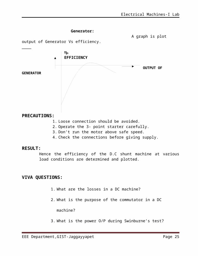
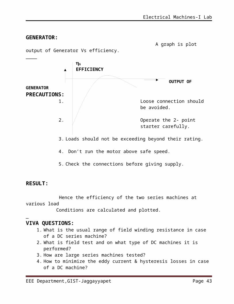
Generator: A graph is plot output of Generator Vs efficiency. G
EFFICIENCY
OUTPUT OF GENERATOR
PRECAUTIONS: 1. Loose connection should be avoided.2. Operate the 3- point starter carefully.3. Don’t run the motor above safe speed. 4. Check the connections before giving supply.
RESULT:Hence the efficiency of the D.C shunt machine at various load conditions are determined and plotted.
VIVA QUESTIONS:
1. What are the losses in a DC machine?
EEE Department,GIST-Jaggayyapet Page 19
Electrical Machines-I Lab
2. What is the purpose of the commutator in a DC machine?
3. What is the power O/P during Swinburne’s test?
4. What is the efficiency of a DC machine during Swinburne’s
test?
5. Why Swinburne’s test cannot be performed on DC series
machine?
EEE Department,GIST-Jaggayyapet Page 20
Electrical Machines-I Lab
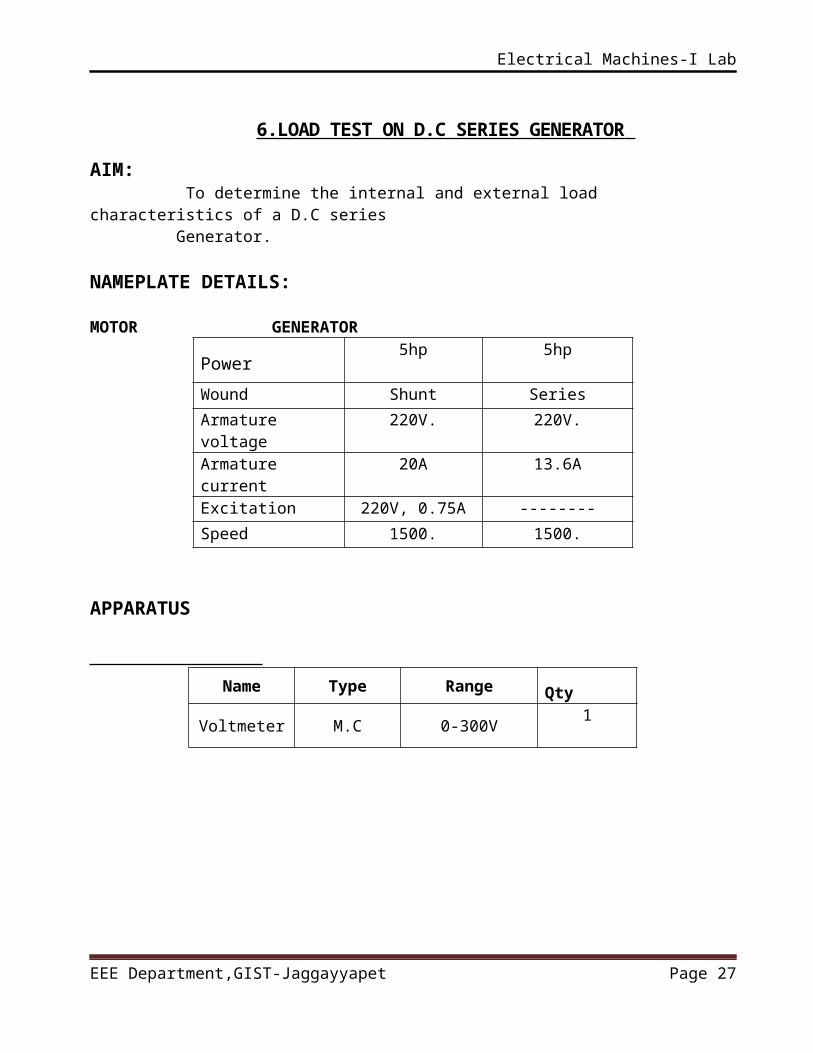
6.LOAD TEST ON D.C SERIES GENERATOR
AIM: To determine the internal and external load characteristics of a D.C series Generator.
NAMEPLATE DETAILS: MOTOR GENERATOR
Power5hp 5hp
Wound Shunt Series
Armature voltage
220V. 220V.
Armature current
20A 13.6A
Excitation 220V, 0.75A --------
Speed 1500. 1500.
APPARATUS
Name Type Range Qty
Voltmeter M.C 0-300V1
Ammeter M.C0-10A 1
Rheostat___
0-300 , 1.7A 1
Tachometer
---1
Load Resistive 5kw1
EEE Department,GIST-Jaggayyapet Page 21
Electrical Machines-I Lab
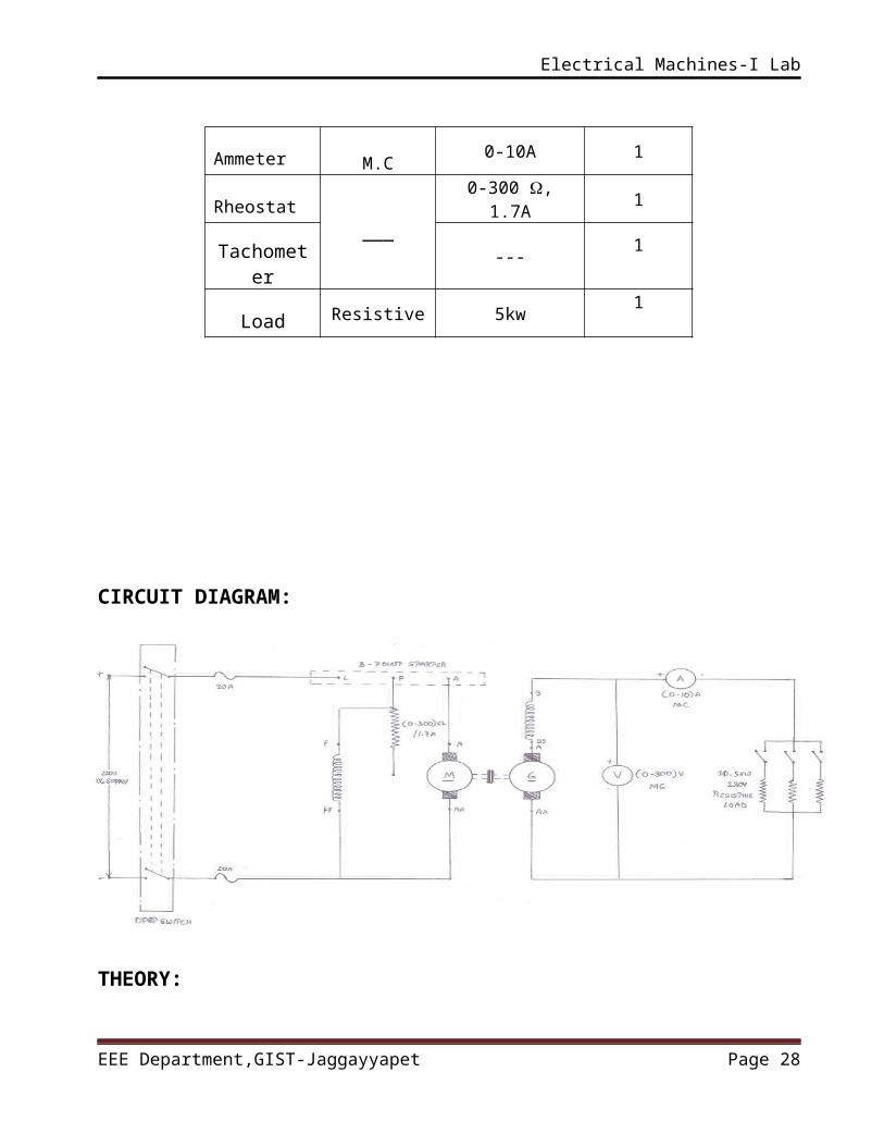
CIRCUIT DIAGRAM:
THEORY: In a series generator, there is only one field winding so that connected in series with armature winding so that whole current flows through winding as well as load, series field winding carries full load current. Therefore series field winding is designed with a fewer turns of thick wire. The resistance of series winding is very low. These generators can be used for few applications and employed as constant current source. By making use of drooping portion of voltage-current characteristics. The best application is for supplying field current for regenerative braking in DC locomotives.
PROCEDURE:1. Connect the circuit as per the circuit diagram.2. Keep the motor field rheostat at minimum position and make sure all the
load switches are in off position3. Start the motor with the help of 3- point starter and adjust the motor
field rheostat till the motor reaches to its rated speed.4. Connect the load in step-by-step and each step note the load current
and terminal voltage of the generator.5. Maintain load current will note exceed rated current.6. After note the readings first switch off the generator load and than
switch off the motor supply.
EEE Department,GIST-Jaggayyapet Page 22
Electrical Machines-I Lab
TABULAR FORM:
S NoVoltage
V(V)
CurrentIa(A) Eg =V+Ia (Ra+Rse)
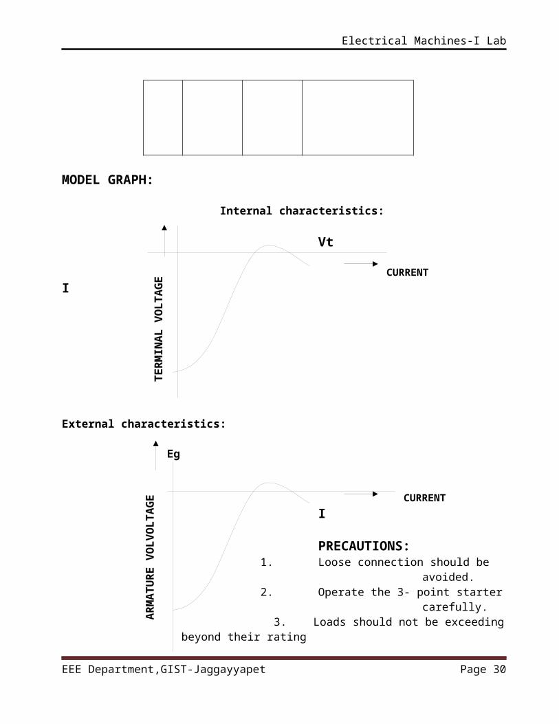
MODEL GRAPH:
Internal characteristics: Vt
CURRENT I
External characteristics:
Eg
CURRENT I
EEE Department,GIST-Jaggayyapet Page 23EF
FIC
IEN
CY
AR
MA
TU
RE
V
OL
VO
LT
AG
ET
ER
MIN
AL
VO
LT
AG
E
Electrical Machines-I Lab
PRECAUTIONS: 1. Loose connection should be avoided.2. Operate the 3- point starter carefully.
3. Loads should not be exceeding beyond their rating
RESULT:
Hence the internal and external load characteristics of a D.C series Generator are obtained and plotted. VIVA QUESTIONS:
1. Can a DC series generator excite on no-load, why?2. What is meant by critical resistance of a DC series generator?3. What are the reasons for the failure of a DC series generator to build up
voltage?4. What are the advantages of a DC series motor?5. Why is the starting torque of the series motor high?
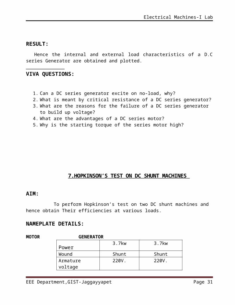
7.HOPKINSON’S TEST ON DC SHUNT MACHINES
AIM:
To perform Hopkinson’s test on two DC shunt machines and hence obtain Their efficiencies at various loads. NAMEPLATE DETAILS: MOTOR GENERATOR
Power3.7kw 3.7kw
Wound Shunt ShuntArmature voltage
220V. 220V.
Armature current
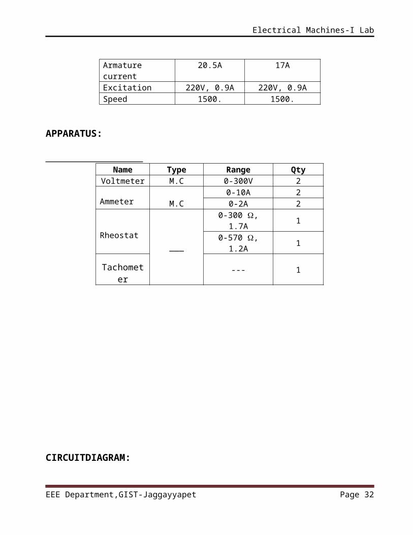
20.5A 17A
Excitation 220V, 0.9A 220V, 0.9ASpeed 1500. 1500.
EEE Department,GIST-Jaggayyapet Page 24
Electrical Machines-I Lab
APPARATUS:
Name Type Range Qty
Voltmeter M.C 0-300V 2
Ammeter M.C0-10A 20-2A 2
Rheostat___
0-300 , 1.7A 10-570 , 1.2A 1
Tachometer
--- 1
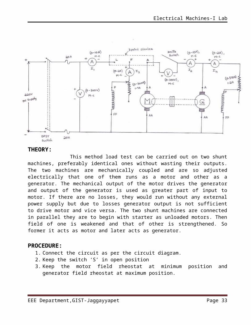
CIRCUITDIAGRAM:
EEE Department,GIST-Jaggayyapet Page 25
Electrical Machines-I Lab
THEORY: This method load test can be carried out on two shunt machines, preferably identical ones without wasting their outputs. The two machines are mechanically coupled and are so adjusted electrically that one of them runs as a motor and other as a generator. The mechanical output of the motor drives the generator and output of the generator is used as greater part of input to motor. If there are no losses, they would run without any external power supply but due to losses generator output is not sufficient to drive motor and vice versa. The two shunt machines are connected in parallel they are to begin with starter as unloaded motors. Then field of one is weakened and that of other is strengthened. So former it acts as motor and later acts as generator.
PROCEDURE:1. Connect the circuit as per the circuit diagram.2. Keep the switch ‘S’ in open position3. Keep the motor field rheostat at minimum position and generator field
rheostat at maximum position.4. Start the motor with the help of 3- point starter and adjust the motor field
rheostat till the motor reaches to its rated speed5. Adjust the field rheostat of the generator till the voltmeter Now close the
switch ‘S’ carefully.6. Decrees the excitation of the motor.Or Increase the excitation of the
generator 7. That means the M.G set is loaded. 8. Take the all meters readings at various conditions.
EEE Department,GIST-Jaggayyapet Page 26
Electrical Machines-I Lab
9. After taking the readings open the switch ‘s’ and then Switch of the motor supply.
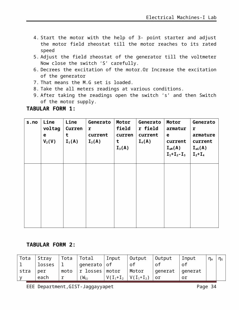
TABULAR FORM 1:
s.no Line voltage V2(V)
Line CurrentI1(A)
Generator current I2(A)
Motor field current I3(A)
Generator field currentI4(A)
Motor armaturecurrent IaM(A)I1+I2-I3
Generator armature current IaG(A)I2+I4
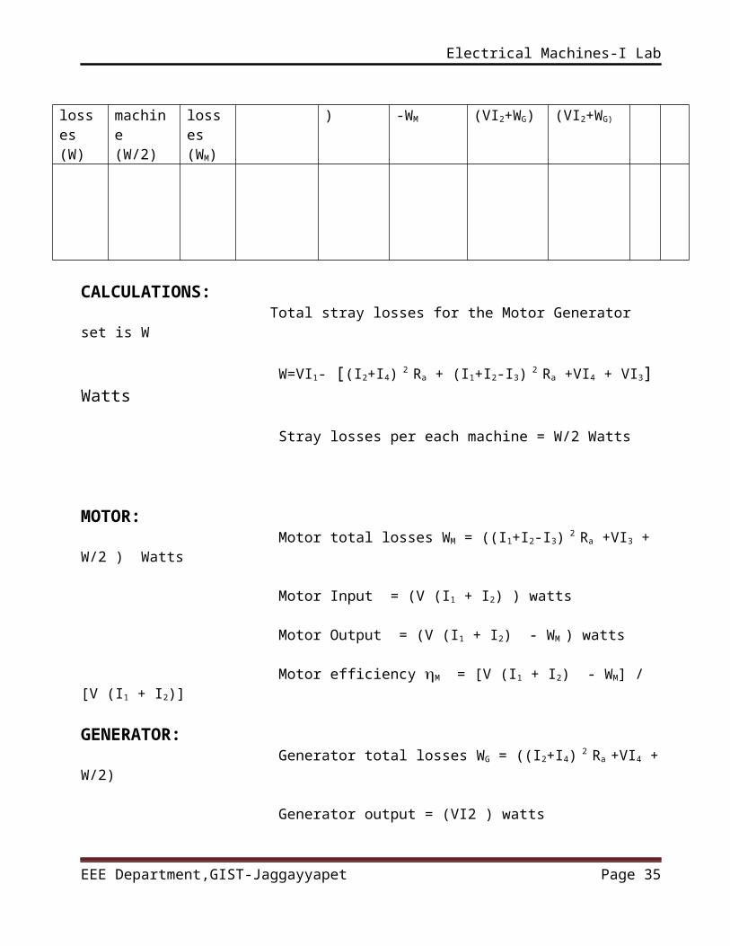
TABULAR FORM 2:
Total stray losses(W)
Stray losses per each machine(W/2)
Total motor losses(WM)
Total generator losses(WG)
Input of motorV(I1+I2)
Output ofMotorV(I1+I2)-WM
Output of generator(VI2+WG)
Input of generator(VI2+WG)
ηm ηG
CALCULATIONS: Total stray losses for the Motor Generator set is W W=VI1- [(I2+I4) 2 Ra + (I1+I2-I3) 2 Ra +VI4 + VI3] Watts Stray losses per each machine = W/2 Watts
EEE Department,GIST-Jaggayyapet Page 27
Electrical Machines-I Lab
MOTOR: Motor total losses WM = ((I1+I2-I3) 2 Ra +VI3 + W/2 ) Watts
Motor Input = (V (I1 + I2) ) watts
Motor Output = (V (I1 + I2) - WM ) watts
Motor efficiency M = [V (I1 + I2) - WM] / [V (I1 + I2)]
GENERATOR: Generator total losses WG = ((I2+I4) 2 Ra +VI4 + W/2)
Generator output = (VI2 ) watts
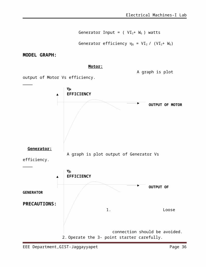
Generator Input = ( VI2+ WG ) watts
Generator efficiency G = VI2 / (VI2+ WG)
MODEL GRAPH: Motor: A graph is plot output of Motor Vs efficiency. M
EFFICIENCY
OUTPUT OF MOTOR
Generator : A graph is plot output of Generator Vs efficiency. G
EFFICIENCY
EEE Department,GIST-Jaggayyapet Page 28
Electrical Machines-I Lab
OUTPUT OF GENERATOR
PRECAUTIONS: 1. Loose connection should be avoided.2. Operate the 3- point starter carefully.3. Loads should not be exceeding beyond their rating.4. Proper rating meters should be used. 5. Check the connections before giving supply.
RESULT: Hence the efficiency of the two machines at various load conditions are calculated and plotted.
VIVA QUESTIONS:1. Which loss is obtained from the Hopkinson’s test?2. Why Hopkinson’s test is also called the regenerative or back-to-back test?3. Is the stray loss obtained from the Hopkinson’s test really same for both
the machines? Why?4. What is the difference between the Swinburne’s test and Hopkinson’s
test?5. Stray loss in a DC machine depends on what quantities?
EEE Department,GIST-Jaggayyapet Page 29
Electrical Machines-I Lab
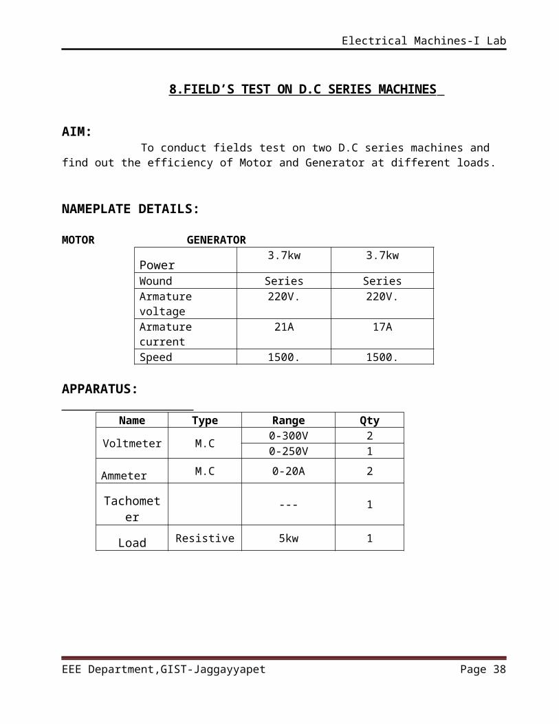
8.FIELD’S TEST ON D.C SERIES MACHINES
AIM: To conduct fields test on two D.C series machines and find out the efficiency of Motor and Generator at different loads.
NAMEPLATE DETAILS: MOTOR GENERATOR
Power3.7kw 3.7kw
Wound Series SeriesArmature voltage
220V. 220V.
Armature current
21A 17A
Speed 1500. 1500.
APPARATUS:
Name Type Range Qty
Voltmeter M.C0-300V 20-250V 1
Ammeter M.C 0-20A 2
Tachometer
--- 1
Load Resistive 5kw 1
CIRCUIT DIAGRAM:
EEE Department,GIST-Jaggayyapet Page 30
Electrical Machines-I Lab
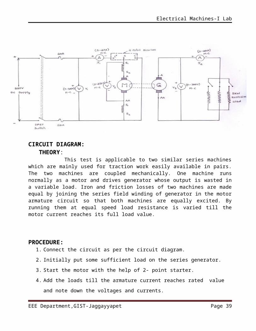
THEORY: This test is applicable to two similar series machines which are mainly used for traction work easily available in pairs. The two machines are coupled mechanically. One machine runs normally as a motor and drives generator whose output is wasted in a variable load. Iron and friction losses of two machines are made equal by joining the series field winding of generator in the motor armature circuit so that both machines are equally excited. By running them at equal speed load resistance is varied till the motor current reaches its full load value.
PROCEDURE:1. Connect the circuit as per the circuit diagram.
2. Initially put some sufficient load on the series generator.
3. Start the motor with the help of 2- point starter.
4. Add the loads till the armature current reaches rated value and note
down the voltages and currents.
5. Reduce the loads step by step and each step note down the voltages and
currents till the motor speed doesn’t exceed safe value.
6. Keep again sufficient load on the series generator and switch off the
motor supply.
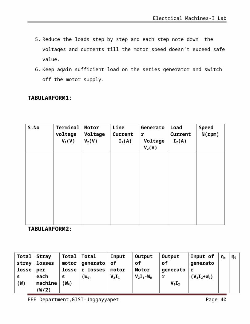
TABULARFORM1:
S.No Terminal voltage V1(V)
MotorVoltage V2(V)
Line Current I1(A)
Generator Voltage V2(V)
LoadCurrent I2(A)
Speed N(rpm)
EEE Department,GIST-Jaggayyapet Page 31
Electrical Machines-I Lab
TABULARFORM2:
Total stray losses(W)
Stray losses per each machine(W/2)
Total motor losses(WM)
Total generator losses(WG)
Input of motorV2I1
Output ofMotorV2I1-WM
Output of generator V3I2
Input of generator(V3I2+WG)
ηm
ηG
CALCULATIONS:
Input of the Motor Generator set is = V1I1 Watts
Output of the Motor Generator set is = V3I2 Watts
Total losses of Motor Generator set is Wt = (VI1- V3I2) Watts
Armature and field losses of the M.G. set
Wcu = ((Ra+2Rse) I12 + I22 Ra ) Watts
Total stray losses for the Motor Generator set is W = Wt-Wcu
Stray losses per each machine Ws= W/2 Watts
MOTOR: Motor total losses WM = ((Ra+Rse) I12 + Ws ) Watts
Motor Input = V2 I1 watts
Motor Output = ( V2 I1 - WM ) watts
EEE Department,GIST-Jaggayyapet Page 32
Electrical Machines-I Lab
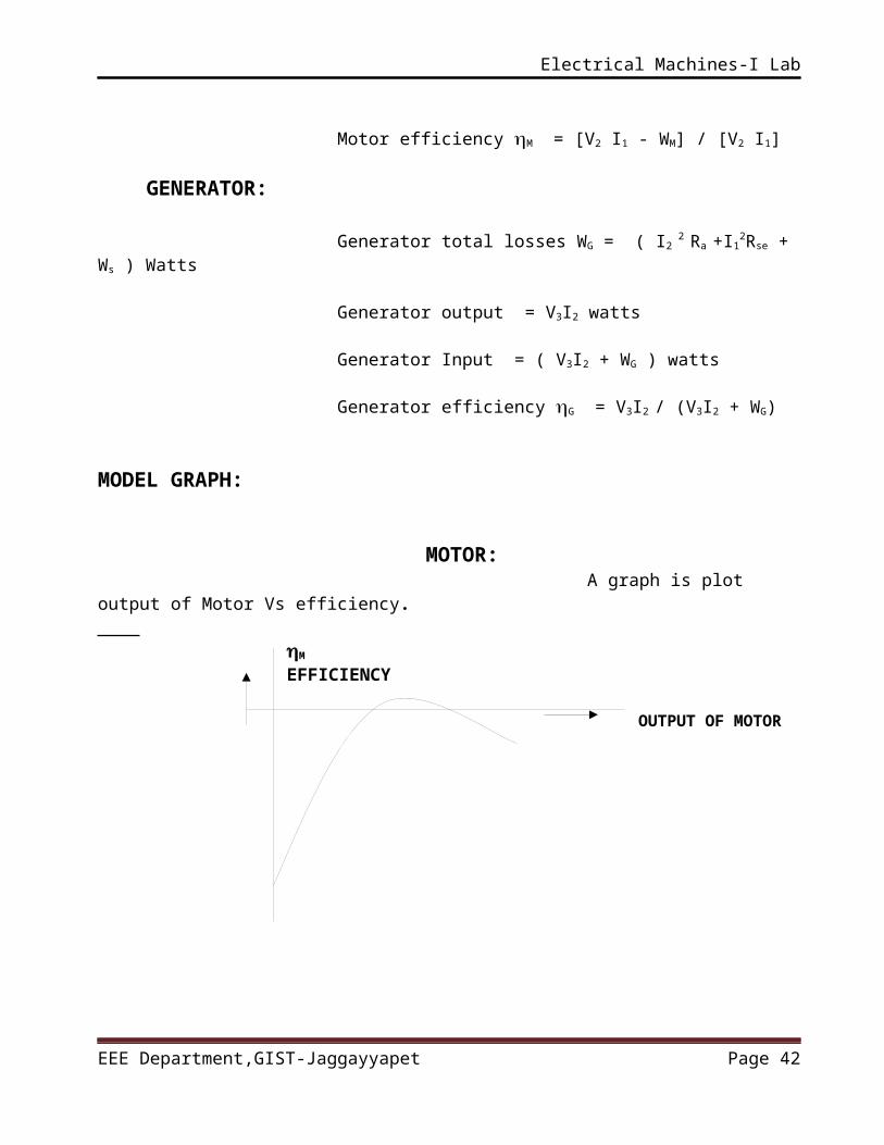
Motor efficiency M = [V2 I1 - WM] / [V2 I1] GENERATOR:
Generator total losses WG = ( I2 2 Ra +I12Rse + Ws ) Watts
Generator output = V3I2 watts
Generator Input = ( V3I2 + WG ) watts
Generator efficiency G = V3I2 / (V3I2 + WG)
MODEL GRAPH:
MOTOR: A graph is plot output of Motor Vs efficiency. M
EFFICIENCY
OUTPUT OF MOTOR
GENERATOR: A graph is plot output of Generator Vs efficiency. G
EFFICIENCY
EEE Department,GIST-Jaggayyapet Page 33
Electrical Machines-I Lab
OUTPUT OF GENERATOR PRECAUTIONS:
1. Loose connection should be avoided.
2. Operate the 2- point starter carefully.
3. Loads should not be exceeding beyond their rating.
4. Don’t run the motor above safe speed.
5. Check the connections before giving supply.
RESULT:
Hence the efficiency of the two series machines at various load Conditions are calculated and plotted. VIVA QUESTIONS:
1. What is the usual range of field winding resistance in case of a DC series machine?
2. What is field test and on what type of DC machines it is performed?3. How are large series machines tested?4. How to minimize the eddy current & hysteresis losses in case of a DC
machine?5. How a DC series motor can be used as DC shunt motor?
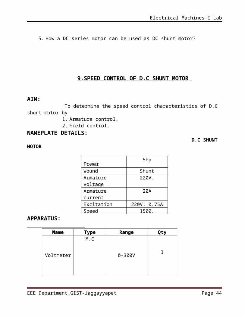
9.SPEED CONTROL OF D.C SHUNT MOTOR
AIM: To determine the speed control characteristics of D.C shunt motor by
1. Armature control.2. Field control.
NAMEPLATE DETAILS: D.C SHUNT MOTOR
Power5hp
Wound ShuntArmature 220V.
EEE Department,GIST-Jaggayyapet Page 34
Electrical Machines-I Lab
voltageArmature current
20A
Excitation 220V, 0.75ASpeed 1500.
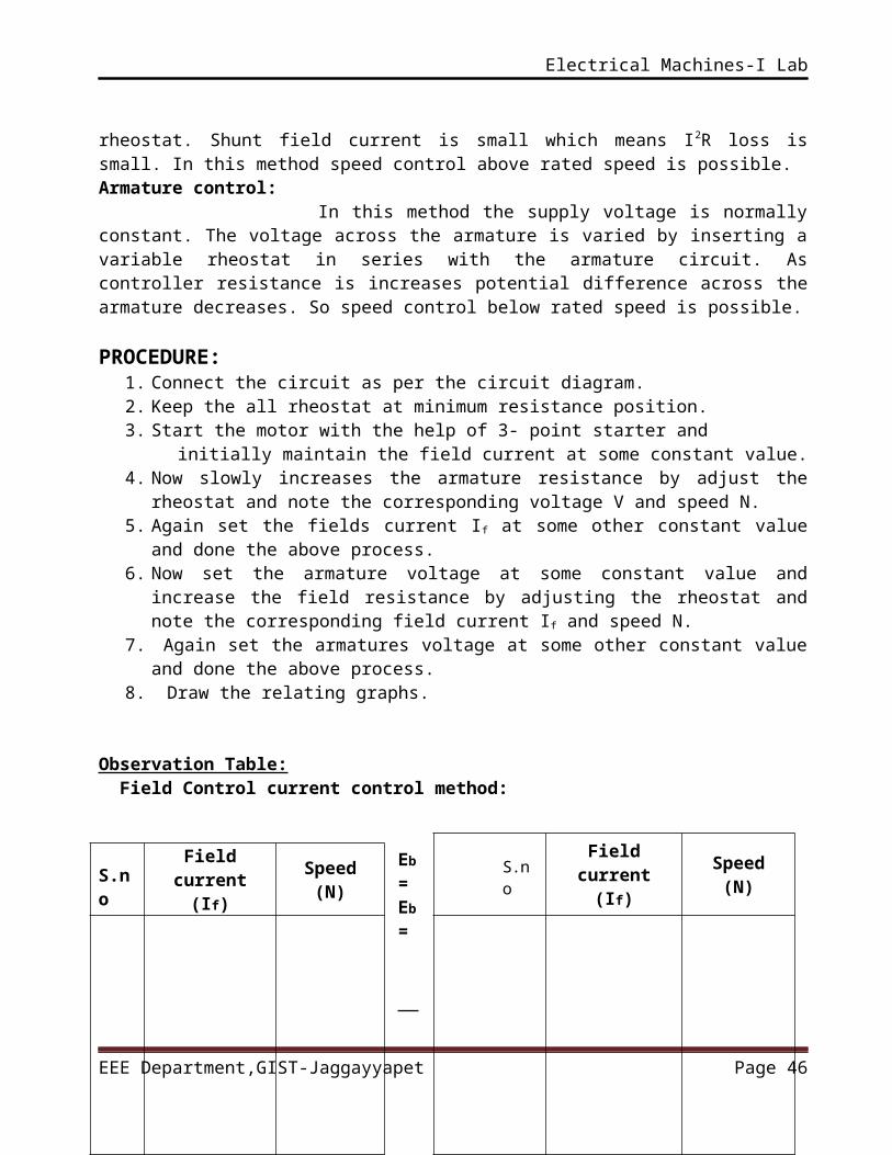
APPARATUS:
Name Type Range Qty
Voltmeter
M.C
0-300V1
Ammeter M.C0-2A 1
Rheostat___
0-300 , 1.7A1
0-36 , 12A1
Tachometer
---1
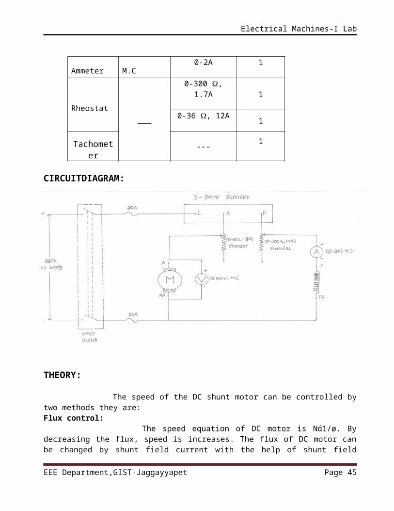
CIRCUITDIAGRAM:
EEE Department,GIST-Jaggayyapet Page 35
Electrical Machines-I Lab
THEORY:
The speed of the DC shunt motor can be controlled by two methods they are:Flux control: The speed equation of DC motor is Nά1/ø. By decreasing the flux, speed is increases. The flux of DC motor can be changed by shunt field current with the help of shunt field rheostat. Shunt field current is small which means I2R loss is small. In this method speed control above rated speed is possible.Armature control: In this method the supply voltage is normally constant. The voltage across the armature is varied by inserting a variable rheostat in series with the armature circuit. As controller resistance is increases potential difference across the armature decreases. So speed control below rated speed is possible.
PROCEDURE:1. Connect the circuit as per the circuit diagram.2. Keep the all rheostat at minimum resistance position.3. Start the motor with the help of 3- point starter and initially maintain the field current at some constant value.4. Now slowly increases the armature resistance by adjust the rheostat and
note the corresponding voltage V and speed N. 5. Again set the fields current If at some other constant value and done the
above process. 6. Now set the armature voltage at some constant value and increase the
field resistance by adjusting the rheostat and note the corresponding field current If and speed N.
7. Again set the armatures voltage at some other constant value and done the above process.
8. Draw the relating graphs.
Observation Table: Field Control current control method:
Eb = Eb =
EEE Department,GIST-Jaggayyapet Page 36
S.no
Field current
(If)
Speed(N)S.n
o
Field current
(If)
Speed(N)
Electrical Machines-I Lab
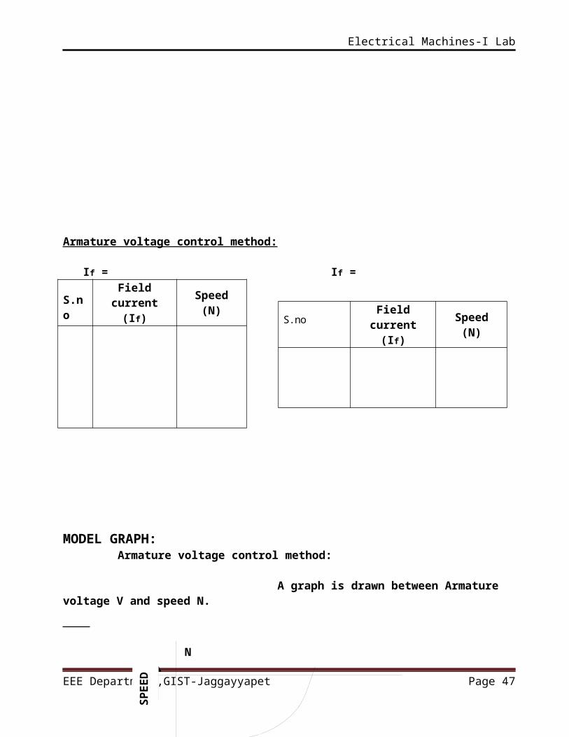
Armature voltage control method:
If = If =
S.no
Field current
(If)
Speed(N)
MODEL GRAPH: Armature voltage control method: A graph is drawn between Armature voltage V and speed N.
N Armature voltage
V
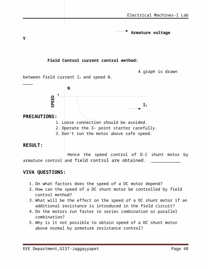
Field Control current control method:
A graph is drawn between field current If and speed N. N
EEE Department,GIST-Jaggayyapet Page 37SP
EE
D
SP
EE
D
S.noField
current(If)
Speed(N)
Electrical Machines-I Lab
If
PRECAUTIONS: 1. Loose connection should be avoided.2. Operate the 3- point starter carefully.3. Don’t run the motor above safe speed.
RESULT:
Hence the speed control of D.C shunt motor by armature control and field control are obtained.
VIVA QUESTIONS:
1. On what factors does the speed of a DC motor depend?2. How can the speed of a DC shunt motor be controlled by field control
method?3. What will be the effect on the speed of a DC shunt motor if an additional
resistance is introduced in the field circuit?4. Do the motors run faster in series combination or parallel combination?5. Why is it not possible to obtain speed of a DC shunt motor above normal
by armature resistance control?
EEE Department,GIST-Jaggayyapet Page 38
Electrical Machines-I Lab
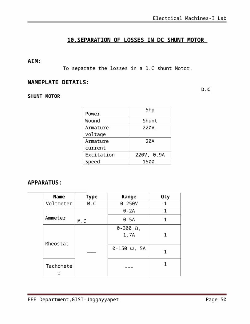
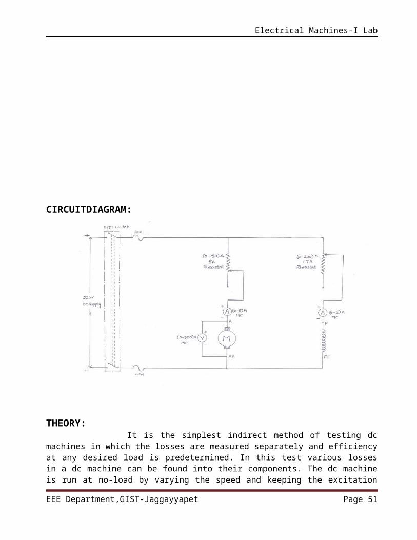
10.SEPARATION OF LOSSES IN DC SHUNT MOTOR
AIM: To separate the losses in a D.C shunt Motor.
NAMEPLATE DETAILS: D.C SHUNT MOTOR
Power5hp
Wound ShuntArmature voltage 220V.Armature current 20AExcitation 220V, 0.9ASpeed 1500.
APPARATUS:
Name Type Range QtyVoltmeter M.C 0-250V 1
Ammeter M.C0-2A 10-5A 1
Rheostat___
0-300 , 1.7A1
0-150 , 5A1
Tachometer
---1
EEE Department,GIST-Jaggayyapet Page 39
Electrical Machines-I Lab
CIRCUITDIAGRAM:
THEORY: It is the simplest indirect method of testing dc machines in which the losses are measured separately and efficiency at any desired load is predetermined. In this test various losses in a dc machine can be found into their components. The dc machine is run at no-load by varying the speed and keeping the excitation constant. If ‘N’ is the speed of the shunt motor at any given time, then the frictional losses are found to be proportional to ‘N’.similarly the windage losses are found to be proportional to N2.
PROCEDURE:1. Connect the circuit as per the circuit diagram.2. Keep the all rheostat at minimum resistance position.3. Start the motor with the help of 3- point starter.4. Adjust the speed of the motor to rated speed by adjusting the field
rheostat.5. Note down the speed, voltage across armature and armature current.6. Keeping the field excitation constant. The speed of the motor can be
varied by controlling the armature voltage by varying the armature resistance.
7. The experiment is repeated at ¾ of the field current
EEE Department,GIST-Jaggayyapet Page 40
Electrical Machines-I Lab
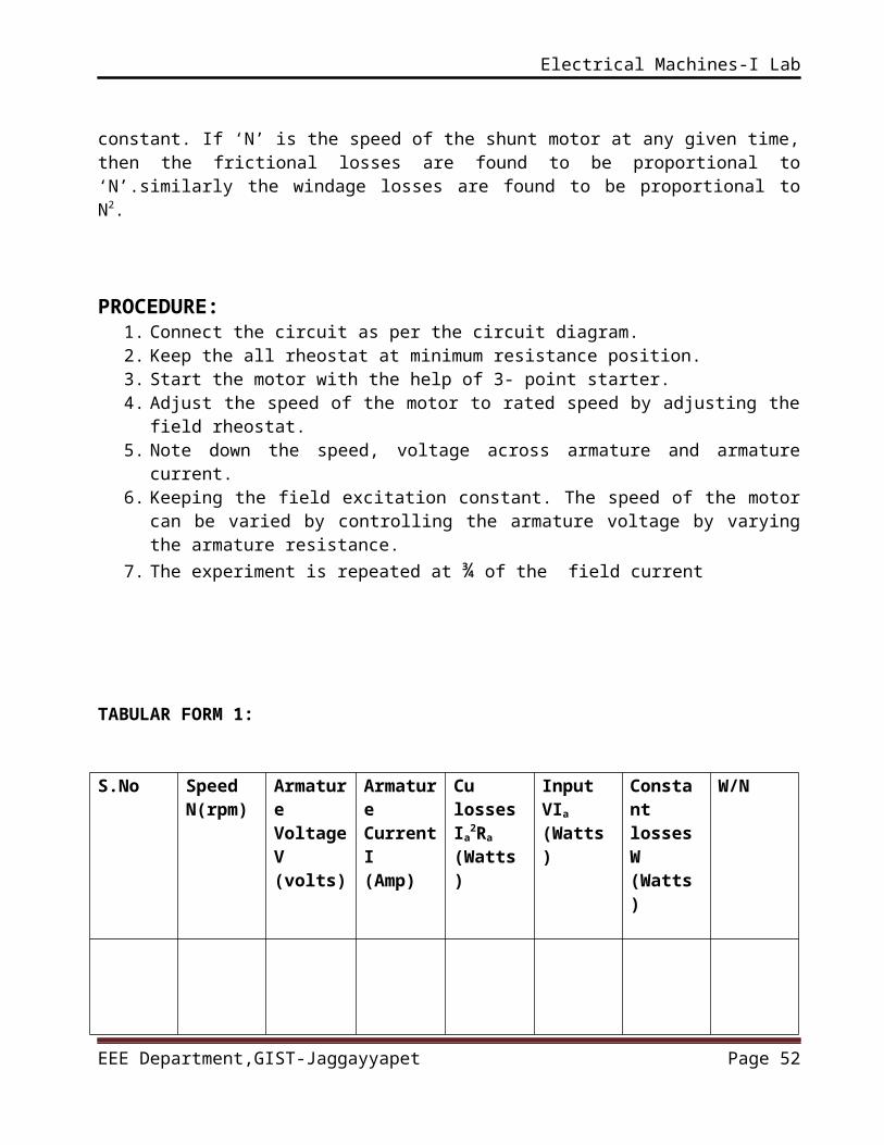
TABULAR FORM 1:
S.No Speed N(rpm)
Armature Voltage V(volts)
Armature Current I(Amp)
Cu lossesIa
2Ra
(Watts)
Input VIa
(Watts)
Constant losses W(Watts)
W/N
¾ Field current If =
S.No.
Speed
(rpm)
Armature
Voltage (V)
Armature
Current (A)
Armature
Cupper losses
I²aRa (W)
InputVIa
(W)
Constant Losses
= VIa-IaRa
(W)
WN
EEE Department,GIST-Jaggayyapet Page 41
Electrical Machines-I Lab
MODEL GRAPH: W N P - - - - - -- - - -- - - - - - - - - - - - - - - - - - - - - - R - - - - - - - - - - - - - - - - - - - - - - - - - - - - - - - -
Speed (N) (rpm)
PRECAUTIONS: 1. Loose connection should be avoided.2. Operate the 3- point starter carefully.3. Don’t run the motor above safe speed.
RESULT: Hence the separation of losses in a DC shunt motor was obtained.
VIVA QUESTIONS:
1. On what factors do hysteresis and eddy current losses depend?2. Why mechanical losses occur in a DC machine?3. What are the magnetic losses in a DC machine?4. Why do iron losses occur in a DC machine?5. Does core loss occur in armature or in the poles of a DC machine?
11.BRAKE TEST ON DC COMPOUND MOTOR
EEE Department,GIST-Jaggayyapet Page 42
Electrical Machines-I Lab
AIM: To find the efficiency of D.C compound motor by a direct load test.
NAMEPLATE DETAILS: D.C COMPOUND MOTOR
Power3.7kw
Wound CompoundArmature voltage 220V.Armature current 20.5AExcitation 220V, 0.9ASpeed 1500rpm.
APPARATUS:
Name Type Range Qty
Voltmeter M.C 0-250V1
Ammeter M.C0-20A 1
Rheostat___
0-300 , 1.7A1
Tachometer
---1
CIRCUIT DIAGRAM:
EEE Department,GIST-Jaggayyapet Page 43
Electrical Machines-I Lab
THEORY: It is a direct method and consists of applying a brake to a water cooled pulley mounted on the shaft of motor. The brake band is fixed with the help of wooden blocks gripping the pulley one end of the band is fixed to earth a spring balance and other is connected to a suspended weight. The motor is running and the load on the motor is adjusted till it carries its full load current. The simple brake test described above can be used for small motors only. Because, in the case of large motors, it is difficult to dissipate the large amount of heat generated at the brake.
PROCEDURE:1. Connect the circuit as per the circuit diagram.2. Keep the motor field rheostat at minimum position.3. Start the motor with the help of 3- point starter and adjust the
motor field rheostat till the motor reaches to its rated speed.4. Now gradually apply the mechanical load by tightening the
belt over the shaft.5. Note the corresponding spring balance readings, line current,
Voltage and speed at particular load.6. Repent the above process at different load condition.7. Before the motor going to be switched off the motor must be in
no load condition.
EEE Department,GIST-Jaggayyapet Page 44
Electrical Machines-I Lab
8. Using the above data deter mine the efficiency of the Compound motor.
CALCULATIONS: Shaft torque = (S1-S2) x r x 9.81 (r = 0.146 m) ω = (2 N) /60. Shaft O/P = Shaft Torque X ω
Efficiency= X100
TABULAR FORM:
S.No Voltage (V)
Current (A)
S1(kg) S2(kg) Speed(rpm)
Input Power(W)
Shaft Torque (N-M)
ωrad/sec
Efficiency
η%
GRAPHS: Graphs are plotted between 1. Speed and output 2. Speed and torque 3. Current and torque 4. Efficiency and out put
MODEL GRAPH:
EEE Department,GIST-Jaggayyapet Page 45
Shaft O/PPower I/P
Electrical Machines-I Lab
N N IL % η O/P Vs % η
T VS IL T VS N
IL VS N
Output(W) Torque(N-m) Torque(N-m) IL(A)
PRECAUTIONS:
1. Loose connection should be avoided.
2. Operate the 4- point starter carefully.
3. Cool the shaft pulley with water.
4. Proper rating meters should be used.
5. Check the connections before giving supply.
RESULT: Hence the efficiency of the D.C compound motor at various load Conditions are calculated and plotted.
VIVA QUESTIONS:
EEE Department,GIST-Jaggayyapet Page 46
Electrical Machines-I Lab
1. What is brake test?2. What is the main drawback of brake test?3. Why brake test is performed with the small machines
only?4. What is the condition for maximum output in a DC
motor?5. What are the possible causes of sparking at brushes?
EEE Department,GIST-Jaggayyapet Page 47
Electrical Machines-I Lab
12.RETARDATION TEST ON DC SHUNT MOTOR
AIM: To conduct retardation test on a given DC machine
NAMEPLATE DETAILS: D.C SHUNT MOTOR
Power5hp
Wound ShuntArmature voltage 220V.Armature current 20AExcitation 220V, 0.9ASpeed 1500.
APPARATUS:
Name Type Range Qty
Voltmeter M.C 0-300V 1
Ammeter M.C 0-5A 1
Rheostat___
0-300 , 1.7A1
0-1500 , 15A0-500Ω,5A 2
Tachometer ---1
EEE Department,GIST-Jaggayyapet Page 48
Electrical Machines-I Lab
CIRCUITDIAGRAM:
THEORY: This test is also known as running down test. It is used for finding out the stray power losses of shunt wound DC machines. In this method of testing dc machines, machine under test is speeded up slightly above its normal speed and supply to the armature is cut off. Consequently the armature slows down and its kinetic energy is utilized to meet the rotational losses. The voltmeter connected across the armature shows the instantaneous back emf of the motor. Since back emf of the motor is directly proportional to speed, therefore, the voltmeter can be suitably calibrated to indicate speed. When the supply to armature is cut off, the speed of the motor decreases. PROCEDURE:
1. Connect the circuit as per the circuit diagram.2. Run the motor at a speed slightly higher than rated speed
by adjusting field external rheostat..3. Disconnect the armature circuit from supply by opening
switch ‘S’. 4. Note down the time taken for the machine to come down to
zero speed.5. Now, once again start the motor and run at a speed slightly
higher than rated speed.6. Disconnect the armature circuit from supply and connect it
across the rheostat by throwing switch ‘S’ into the position 1”& 2”.
EEE Department,GIST-Jaggayyapet Page 49
Electrical Machines-I Lab
7. Note down the readings of voltmeter and ammeter for two speeds and time taken for the machine to come down to zero speed.
OBSERVATIONSWithout load: With load:
Time taken = seconds (with load)
CALCULATIONS: Rotational losses W=W’ (dt2)
(dt1-dt2)Where W’=average load power=VavgIavg wattsdt2 is the time taken for the speed to come down from N1to N2 with load.
EEE Department,GIST-Jaggayyapet Page 50
S .no Speed (rpm)
Time (sec)
S .no Speed (rpm)
Time (sec)
Speed (rpm) V IL Vavg Iavg
N1=N2=
Electrical Machines-I Lab
dt1 is the time taken for the speed to come down from N1to N2 under no-load.
MODEL GRAPH:speed (rpm)
N1 No-load
N2 With load
Time (sec)
PRECAUTIONS: 1. Loose connection should be avoided.2. Operate the 3- point starter carefully.3. Don’t run the motor above safe speed.
RESULT: Hence the separation of losses in a DC shunt motor was obtained.
VIVA QUESTIONS:
1. What is retardation test and on what type of dc machines it is performed?
EEE Department,GIST-Jaggayyapet Page 51
Electrical Machines-I Lab
2. What are the stray losses in a DC machine?3. The lost torque in a DC motor is proportional to which loss?
EEE Department,GIST-Jaggayyapet Page 52