Embed Size (px)
Citation preview

Report No. 050-S-07b-5
INSTALLATION AND OPERATION MANUAL
B-Vent Gas Fireplace Insert
Retain These Instructions For Future Reference
WARNINGS• Hot! Do not touch! The glass and surfaces of this appliance will be hot during operation and will
retain heat for a while after shutting off the appliance. Severe burns may result. • Carefully supervise children in the same room as appliance.
FOR YOUR SAFETYDo not store or use gasoline or other flammable vapors or liquids in the vicinity of this or any other appliance.WHAT TO DO IF YOU SMELL GAS:• DO NOT light any appliance.• DO NOT touch any electrical switch; do not use any phone in your building.• Immediately call your gas supplier from a neighbor’s phone. Follow your gas supplier's instructions.• If your gas supplier cannot be reached, call the fire department.Installation and service must be performed by a quali-fied installer, service agency or the gas supplier.
POUR VOTRE SÉCURITÉ: Ne pas entreposer ni utiliser d'essence ni d'autres vapeurs ou liquides inflammables à proximité de cet appareil ou de tout autre appareil. POUR VOTRE SÉCURITÉ: Que faire si vous sentez une odeur de gaz:• Ne pas tenter d'allumer d'appareil.• Ne touchez à aucun interrupteur. • Ne pas vous servir des téléphones se trouvant dans le bâti-
ment • Appelez immédiatement votre fournisseur de gaz depuis un
voisin. Suivez les instructions du fournisseur.• Si vous ne pouvez rejoindre le fournisseur de gaz, appelez
le service des incendies.L'installation et l'entretien doivent être assurés par un installateur ou un service d'entretien qualifié ou par le fournisseur de gaz.
WARNING: If the information in this manual is not followed exactly, a fire or explosion may result causing property damage, personal injury or loss of life.
AVERTISSEMENT: Assurez-vous de bien suivre les instruc-tions données dans cette notice pour réduire au minimum le risque d’incendie ou d’explosion ou pour éviter tout dommage matériel, toute blessure ou la mort.
A French manual is available upon request. Order P/N 775,225CF.Ce manuel d’installation est disponible en francais, simplement
en faire la demande. Numéro de la pièce 775,225CF.
• Suitable for installation into masonry or factory built fireplaces. These appliances may be installed in an after-market permanently located, manufactured (mobile) home (USA only), where not prohibited by local codes. This appliance is only for use with the type of gas indicated on the rating plate. This appliance is not convertible for use with other gases unless a certified kit is used.
• Lennox™ gas-burning appliances are designed for use as a supplemental heater. They are not intended for continuous use as a primary heat source.
Firestar™ (GC3)
P/N 775,225M Rev. B, 08/2007
In the Commonwealth of Massachusetts: • Installation must be performed by a licensed plumber or gas fitter • See Table of Contents for location of additional Commonwealth of Massachusetts requirements
™

�
FOR YOUR SAFETY do not install or operate your Fire-star™ gas insert without first reading & understanding this manual. Any installation or operation of the appli-ance deviating from that which is stated in this manual WILL void the warranty & may be hazardous.
INSTALLATION & REPAIR SHOULD ONLY BE DONE BY A QUALIFIED SERVICE TECHNICIAN. DO NOT ATTEMPT TO SERVICE THE APPLIANCE YOURSELF.
The insert should be inspected & cleaned before use & at least annually by a qualified service technician. More frequent cleaning may be required due to exces-sive lint from bedding material, carpeting, etc.
It is imperative that control compartments, burners, & circulating air passageways of the room heater be kept clean.
Adequate clearances around the combustion chamber and accessibility clearances for servicing & proper operation must be maintained.
Turn off the gas before servicing this appliance. It is recommended that a qualified service technician per-form an appliance check-up at the beginning of each heating season.
All installations must conform with all local, state, & national codes. In the absence of local codes, the installation must conform with National Fuel Gas Code ANSI Z��3.1-latest edition, also known as NFPA 54 (In Canada, the current CAN/CSA B149.1 installation code). Refer to the National Fuel Gas Code & local zoning & code authorities for details on installation requirements. Your Firestar gas insert must be vented to the outside in accordance with the latest edition of the National Fuel Gas Code.
This gas insert MUST be vented directly to the outside & MUST NEVER be attached to a chimney serving a separate solid fuel burning appliance. Each gas appli-ance MUST USE a separate vent system. Common vent systems are PROHIBITED.
This appliance uses room air for combustion. It is im-perative that provisions for adequate combustion and ventilation air be made. This appliance is NOT designed to and will not operate in a negative pressure. Contact your dealer if you suspect such a situation exists.
Mobile home installations must conform with the Mobile Home Construction and Safety Standard, Title �4 CFR, Part 3�80(inCanadaCAN/CSAZ240MH), or, when such a standard is not applicable, the Standard for Mobile Home Installations, ANSI A��5.1 - latest edition.
The appliance, when installed, must be electrically grounded in accordance with local codes or in the ab-sence of local codes, with the National Electrical Code, ANSI/NFPA 70 - latest edition. In Canada, the current CSA C��-1 Canadian Electrical Code - latest edition.
Do not make any make-shift compromises during in-stallation. Any modification or alteration may result in damage to the appliance or dwelling and will void the warranty, certification and listings of this unit.
Failure to use manufacturer provided parts, variations in techniques and construction materials or practices other than those described in this manual may create a fire hazard and void the limited warranty.
Your Lennox™ gas insert must be equipped for the proper fuel type & altitude at which it will be operated. Any operation outside the parameters outlined in this manual may result in a hazardous condition & will void the warranty. Please carefully read the sections pertain-ing to these subjects and/or be sure your appliance is properly equipped.
Do not use this insert if any part has been under water. Immediately call a qualified service technician to inspect the appliance & to replace any part of the control system & any gas control which has been under water.
Due to high temperatures, the insert should be located out of traffic areas & away from furniture & draper-ies.
Children & adults should be alerted to the hazards of high surface temperature & should stay away to avoid burns or clothing ignition. Young children should be carefully supervised when they are in the same room as the Lennox gas insert. Clothing or any other flammable material should not be placed on or near the insert.
Never use solid fuels such as wood, paper, cardboard, coal, or any flammable liquids, etc., in this appli-ance.
Any grill, panel, or glass removed for service MUST be replaced prior to operating the insert. Do not operate appliance with the glass front removed, cracked or broken. Replacement of the glass should be done by a qualified service technician.
DO NOT USE abrasive cleaner on the glass door assem-bly. DO NOT ATTEMPT to clean the glass door when it is hot.
Gold & nickel plated surfaces must be cleaned with glass cleaner & a clean soft cloth before firing the first time or fingerprints will remain permanently. NEVER use brass polish to clean gold or nickel, this will remove the plating!!!
When opening the lower door on the face while the insert is burning, pull at the far left or far right vent openings, because the door is hot during operation.
Lennox Hearth Products, its employees, or any of its representatives assume no responsibility for any dam-ages caused by an inoperable, inadequate, or unsafe condition as a result of any improper operation, service or installation procedures, whether direct or indirect.
INSTALLER: THESE INSTRUCTIONS ARE TO REMAIN WITH THE HOME OWNER!
Cautions & safety
3
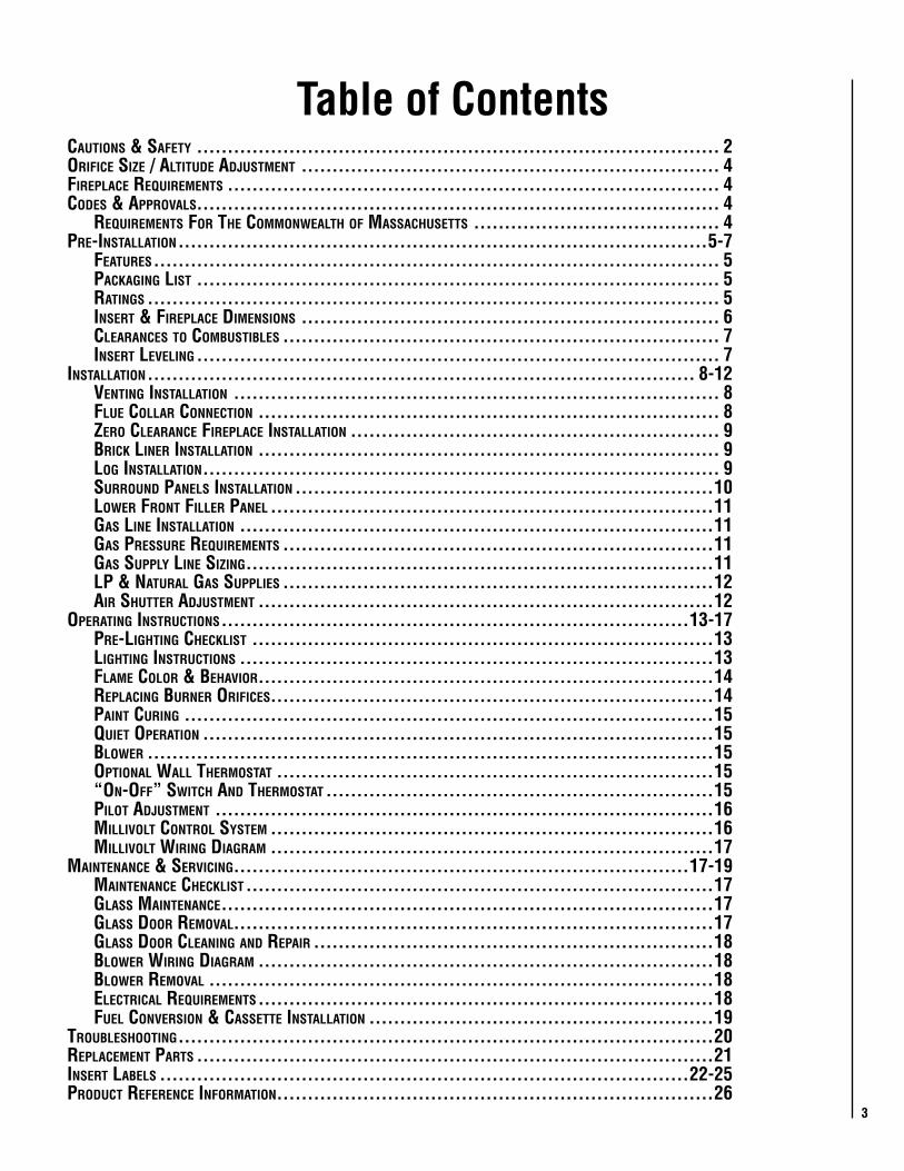
Table of ContentsCautions & safety ..................................................................................... 2orifiCe size / altitude adjustment .................................................................... 4fireplaCe requirements ................................................................................ 4Codes & approvals..................................................................................... 4 requirements for the Commonwealth of massaChusetts ........................................ 4pre-installation ......................................................................................5-7 features ............................................................................................ 5 paCkaging list ..................................................................................... 5 ratings ............................................................................................. 5 insert & fireplaCe dimensions .................................................................... 6 ClearanCes to Combustibles ....................................................................... 7 insert leveling ..................................................................................... 7installation ......................................................................................... 8-12 venting installation ............................................................................... 8 flue Collar ConneCtion ........................................................................... 8 zero ClearanCe fireplaCe installation ............................................................ 9 briCk liner installation ........................................................................... 9 log installation .................................................................................... 9 surround panels installation ....................................................................10 lower front filler panel ........................................................................11 gas line installation .............................................................................11 gas pressure requirements ......................................................................11 gas supply line sizing ............................................................................11 lp & natural gas supplies ......................................................................12 air shutter adjustment ..........................................................................12operating instruCtions ............................................................................13-17 pre-lighting CheCklist ...........................................................................13 lighting instruCtions .............................................................................13 flame Color & behavior ..........................................................................14 replaCing burner orifiCes........................................................................14 paint Curing ......................................................................................15 quiet operation ...................................................................................15 blower ............................................................................................15 optional wall thermostat .......................................................................15 “on-off” switCh and thermostat ...............................................................15 pilot adjustment .................................................................................16 millivolt Control system ........................................................................16 millivolt wiring diagram ........................................................................17maintenanCe & serviCing..........................................................................17-19 maintenanCe CheCklist ............................................................................17 glass maintenanCe ................................................................................17 glass door removal..............................................................................17 glass door Cleaning and repair .................................................................18 blower wiring diagram ..........................................................................18 blower removal ..................................................................................18 eleCtriCal requirements ..........................................................................18 fuel Conversion & Cassette installation ........................................................19troubleshooting .......................................................................................20replaCement parts ....................................................................................21insert labels ......................................................................................22-25produCt referenCe information .......................................................................26

4
Smoke Detectors
Sincetherearealwaysseveralpotentialsourcesoffireinanyhome,werecommendinstallingsmokedetectors.Ifpossible,installthesmokedetectorinahallwayadjacenttotheroom(toreducethepossibilityofoccasionalfalseactivationfromtheheatproducedbytheappliance).Ifyourlocalcoderequiresasmokedetectorbeinstalledwithinthesameroom,youmustfollowtherequirementsofyourlocalcode.Checkwithyourlocalbuildingdepartmentforrequirementsinyourarea.
Codes & Approvals
CertifiCationGasappliancesmustbe testedandcertifiedbyanation-allyrecognizedtestingandcertificationlaboratorytoANSI(AmericanNationalStandardInstitute)gasappliancesafetystandards.This insert has been tested and certified by OMNI -TestLaboratoriestoANSIZ21.88-2005/CSA2.33-2005StandardforVentedGasFireplaceHeaterandCGA2.17-M91andUL307B Gas Burning Heating Appliances for Manufactured(Mobile)HomesinbothUSAandCanada.IthasmetallnecessaryANSIStandardsandisfullycertifiedforinstallationinanycommunity.IfthereareanyquestionsorifyouneedfurthersubstantiationeitherwritetoorcallyourLennoxHearthProductsdealer. If youhave furtherquestions,pleasecontactLennoxHearthProducts.Checkalllocalbuildingandsafetycodesbeforeinstallation.Theinstallationinstructionsandappropriatecoderequire-mentsmustbefollowedexactlyandwithoutcompromise.Intheabsenceoflocalcodesthefollowingstandardsandcodesmustbefollowed.
new york City, new york (mea)
Installationof thesefireplacesareapproved for installationinNewYorkCityintheUSstateofNewYork(MEA#:138-07-E).
Commonwealth of massaChusetts requirements
Installationofthesefireplacesareapprovedforinstallationin theUSstateofMassachusetts if the followingadditionalrequirementsaremet-• Installationandrepairmustbedonebyaplumberorgas
fitterlicensedintheCommonwealthofMassachusetts.• Theflexiblegas lineconnectorusedshallnotexceed36
inches(92centimeters)inlength.• The individual manual shut-off must be a T-handle type
valve.
Orifice Size/Altitude AdjustmentForaltitudesabove2,000feet(InCanada4,500FT/1370M),theorificeshouldbede-ratedby4%forevery1,000feettomaintaintheproperratioofgastoair.Improperorificesizingmayresultindamageandunsafeconditions.Changingtheorificeshouldonlybedonebyaqualifiedservicetechnician.ContactyourLennoxHearthProductsdealerforproperorificesizes.(seePage21and24formoreinformation).
The Firestar™ Insert• Mustconformwithalllocal,state,andnationalinstallation
codes.Intheabsenceoflocalcodes,theinstallationmustconformwithNationalFuelGasCodeANSIZ223.1-latestedition, also known as NFPA 54 (In Canada, the currentCAN/CSAB149.1installationcode).RefertotheNationalFuelGasCodeand local zoningandcodeauthorities fordetailsoninstallationrequirements.
• MobilehomeinstallationsmustconformwiththeMobileHome Construction and Safety Standard, Title 24 CFR,Part3280(inCanadaCAN/CSAZ240MH),or,whensuchastandardisnotapplicable,theStandardforMobileHomeInstallations,ANSIA225.1-latestedition.
• MustbeventeddirectlytotheoutsideinaccordancewiththelatesteditionoftheNationalFuelGasCodeandmustneverbeattachedtoachimneyservingaseparatesolidfuelburningappliance.
• Usesroomairforcombustion.Itisimperativethatprovi-sionsforadequatecombustionandventilationairbemade.ThisapplianceisNOTdesignedtoandwillnotoperateinanegativepressure.Contactyourdealerifyoususpectsuchasituationexists.
• Hasbeencertifiedforusewitheithernaturalgasorpro-pane.
• Isnotforusewithsolidfuels.• Isapprovedforsittingroomsand/orbedrooms.
Fireplace RequirementsThese heaters are designed to be installed into an existingmasonryfireplace(builttoUBC37orULCS628standards)or factorybuilt solid fuel,woodburningfireplace (listed toUL127orULCS610)only.Allexhaustgasesmustbeventedoutsidethestructure.Combustionairisdrawnfromoutsidethestructure.Wheninstallinginafactorybuiltfireplace,thefireplace grate must be removed and the damper must beremovedorsecuredopen.Ifthefactory-builtfireplacehasnogasaccesshole(s)provided,anaccessholeof1-1/2inches(38mm)orlessmaybedrilledthroughthelowersidesorbottomofthefireboxinaproperworkmanshiplikemanner.Thisaccessholemustbepluggedwithanon-combustible insulationafter thegassupply linehasbeeninstalled.Theinstallermustmechanicallyattachthemarkingsuppliedwiththegasfireplaceinserttotheinsideofthefireboxofthefireplaceintowhichthegasfireplaceinsertisinstalled.IMPORTANT: When installing these appliances into a factory built fireplace or heat-form, the air flow within and around the fireplace shall not be altered by the installation of the insert (i.e. DO NOT BLOCK louvers or cooling air inlet or outlet ports, circulating air chambers in a steel fireplace liner or metal heat circulator).
WARNINGTHIS FIREPLACE HAS BEEN ALTERED TO
ACCOMMODATE A FIREPLACE INSERT AND SHOULD BE INSPECTED BY A QUALIFIED
PERSON PRIOR TO RE-USE AS A CONVENTIONAL FIREPLACE.

5
Pre-Installation
features
Installation Options
Residential-VentedVerticalOnly Manufactured(Mobile)Home NaturalGasOrPropane(LP) Bedrooms OptionalWall-mountedOrRemoteThermostat
Electrical
The fan motor requires 120 Volts AC for operation. Thefireplaceisnotdependentonthefanoranoutsideelectricalsupplytooperate.
Millivolt Valve
Thisinsertisoperatedwithamillivoltvalveandthereforeburnsevenduringapoweroutage.
Fuel
Thisinsertcomesfromthefactoryequippedtoburnnaturalgasataspecifiedelevation.The insertcanbeconvertedtoburnLP(liquidpropane)byinstallingaconversionkit.OnlyLennoxHearthProductsconversionkitscanbeusedtoconvertfromNGtoLPorLPtoNG.ContactyourLennoxHearthProductsdealerfordetails.
paCkaging list
To install a Firestar insert, an insert body, and surround(flange)kitarerequired.
Insert Body Packaging List
1InsertBodywithBurnerCassetteandtrivet 1SetofRefractoryBrickPanels-3pieces(H5866) 1LogSet(H5860) 1 Lowerfront2”fillerpanel 1Fasteners:6slotted1/4"trussscrews 4speednuts 6springclips 4-3/8”x3”levelingbolts 2socketheadscrews 1InstallationandOperationManual
Surround Kits - One Required (sold separately)
�9 X 41” Black Trim (7507�) �9 X 48” Black Trim (75073) 33 X 41” Black Trim (75074) 33 X 48” Black Trim (75075)
Surround Kit Contents
1TopSurround2SideSurrounds3BlackTrimPieces2ElbowedTrimFasteners
RATINGS Firestar™ (GC3)
NATURAL GAS LP GAS
MAX/MIN INPUT BTUH 0-2,000 FT (0-610 M)u 39,000/27,500 39,000/22,600
MANIFOLD PRESSURE (IN. WC) 1.7 - 3.5 3.5 - 10.0
MIN./MAX. INLET PRESSURE (IN. WC) 5.0 - 10.5 10.5 - 13.0
MAXIMUM HEAT OUTPUT BTUS/ HOUR “STEADY STATE” 31,200 31,200
P4 Efficiency v 67.09% 69.02%
ORIFICE (DMS) 0-2,000 FT (0-610 M)u #33 #49
uUnit factory equipped for 0-�000 FT/0-610 M, In Canada 0-4500 FT/0-1370 MvTested to CSA P.4.1-0� “Testing Method for Measuring Annual Fireplace Efficiency.Electrical Rating: 1�0 VAC, 60 HZ, Less Than � Amps

6
Figure �
minimum fireplaCe opening required
A = 29-3/4”(756mm)FrontOpeningB = 19”(483mm)HeightC = 19”(483mm)RearWidthD = 15-1/4”(387mm)FireplaceDepth
minimum fireplaCe Cavity
Insert DimensionsWidth of insert behind Surround Panels �6-3/4” (680mm)
Rear height 18-7/8” (479mm)
Insert depth into fireplace 13-5/8” (346mm)
Flue center line from back of surround with standard draft hood 11-3/8” (�89mm)
Flue collar diameter (OD) 3-15/16” (100mm)
A
B
C
D
insert dimensions
SeeFigures1,2and3showinginsertdimensionsandmini-mumfireplacefireboxdimensionstoaidyouindeterminingproperfitintoexistingfireplace.
Figure 1
Figure 3
23-3/4” (603mm)
11-3/8”(289mm)
9-7/8”(251mm)
4” (102mm)
20-3/8”(518mm)
19”(583mm)
7-3/8”(187mm)
13-3/4” (349mm)
24-3/4” (629mm)
10-1/2”(267mm)
20”(508mm)
*2”(51mm)
41” (1041mm)26-3/4” (680mm)26-1/4” (667mm)
13-3/4”(349mm)
7-3/8”(187mm)
2-1/8”(54mm)
33-1/2”(851mm)
9-7/8”251mm)
11-3/8”(289mm)
*Equippedfromthefactorywitha2”filler.Contactyourdealerforadditionalinformation.
CAUTIONS • Trim panels or surrounds must not seal ventila-
tion openings in the existing fireplace that the appliance is installed in.
• The fireplace in which this gas insert is to be installed must be thoroughly cleaned if it has been used to burn wood or synthetic logs. Have the chimney and all inside surfaces of the fire-place brushed and vacuumed so that no soot, embers, or loose combustion deposits can be drawn into the heat circulation blower and blown into the living area.
• If any portion of the chimney system shows signs of structural or mechanical weaknesses, such as: cracks, leaky joints, corroded or warped surfaces, the faulty portion must be repaired or replaced prior to installing this appliance.
• The factory built firebox must accept the insert without modification other than removing bolted or screwed together pieces such as baffles / smoke shelf / deflectors, ash lips, glass door, screen or door tracks, log grates, refractory or masonry lining and damper assemblies. Any fireplace component, which is removed, must be retained so they can be reinstalled to restore the fireplace to its original operating condition. The removal of any part must not alter the integrity of the outer shell of the pre-engineered fireplace cabinet in any way. Any parts removed must be replaceable. If any components are removed from (or altered) from the existing fireplace, a Warning Label (see Page4) must be affixed inside the fireplace firebox, so that it shall be visible upon removal of the fireplace insert. Note: RTV high temperature silicone is an approved adhesive to affix the label.

7NOTE: DIAGRAMS & ILLUSTRATIONS ARE NOT TO SCALE.
(*Insertbottomisthemetallipbelowthelowergoldtrimbar).
Note: Hearth protection to be min. 3/8” (10mm) thick non-combustible or equivalent, with a k factor of .84.
insert leveling
TheFireStar™insertcomeswithfour3/8”x3”levelingbolts(twoforuseattherearandtwoatthefrontoftheinsert).Thetwoattherearcanbeusedtoraisethebackoftheinsertrestingonthefireplacehearth.Thetwoatthefrontcanbeusedtoadjustthefrontoftheinsertonthehearthextension.Toinstalltheboltsa3/8”nutshouldbethreadedontothebolt,followedbya3/8”flatwasher.Theboltshouldthenbeinstalledfromtheundersideoftheinsertintothecaptivenutinthebottomoftheinsert.Whentheboltisadjustedtotheproperheightthenutpreviouslythreadedontotheboltcanbesnuggeduptotheinsertbottom.
Hearth / Floor Protection
minimum ClearanCes to Combustibles
Minimum clearances include any projections such as shelves, window sills, mantels, spacers/standoffs or surfaces to combustible construction etc. above the ap-pliance. Paint or lacquer used to finish the mantel must be heat resistant in order to avoid discoloration.
The letters below, C through H, correspond to Figure 4showingminimumclearancesrequiredfromtheappliancetocombustiblesandtheminimumprojectionofthehearthextension.
C=6-1/2”(165mm)toSideFacing,3/4”(19mm)orLessD=11”(279mm)toSideWallE=24”toMantel**,morethan3/4”(19mm)F=14-1/2”(368mm)toTopFacing,maximumthickness3/4”(19mm)
hearth proteCtion
G= MinimumHearthProtectionfromFrontofInsert*H= VerticalDistancefromInsertBottomtoCombustible
Material.
ClearanCes
Figure 4
E** F
HD
C
Trim
Mantel
G
G 23”(584mm)
20”(508mm)
17”(432mm)
0”(0mm)
H 0”(0mm)
2”(51mm)
4”(102mm)
6”(152mm)
**Theminimumdistance from the topof the insert to acombustible may be reduced to 16” (406mm) with amantelshield.Theshieldshouldbemadefrom18-gageorthickersheetmetal,7”by33”(178mmby838mm).Theshieldmustbecenteredovertheinsertandspacedoneinchbelowthemantel.Theshieldcanbefastenedtoandspacedfromthemantelusingfourtosixscrews.
WARNING B-Vent appliances are not designed to operate in negatively pressured environments (pressure within the home is less than pressures outside). Significant negatively pressured environments caused by weather, home design, or other devices may impact the operation of these appliances. Negative pressures may result in poor flame appearance, sooting, damage to property and/or severe personal injury. Do not operate these appliances in negatively pressured environments. Providing adequate ventilation to the appliance for combustion air will eliminate a negative pressure environment.

8 NOTE: DIAGRAMS & ILLUSTRATIONS ARE NOT TO SCALE.
Installation
insert venting
Refer to Figure 6 which shows a typical installation of this ap-pliance into an existing solid-fuel fireplace.
WARNING:Thisapplianceisequippedwithasafetycontrolsys-temdesignedtoprotectagainstimproperventingofcombustionproducts.Operationofthisheaterwhennotconnectedtoaprop-erlyinstalledandmaintainedventingsystemortamperingwiththeblockedventshut-offsystemcanresultincarbonmonoxide(CO)poisoningandpossibledeath.
InsertmustbeventedtotheoutsideinaccordancewiththecurrenteditionoftheNationalFuelGasCodeANSI-Z223.1-latestedition,alsoknownasNFPA54(InCanada,thecurrentCAN/CSAB149.1installationcode).Theinsertmust not beconnectedtoachimneyflueservingaseparatesolidfuelburningappliance.
Thisgasinsertrequiresa4”diameterB-ventorlistedflexalu-minum or stainless chimney liner extending the entire lengthof the chimney to ensure proper operation. The vent shouldterminatewithachimneycapor raincap.Chimneyshouldbesealedaroundcaptopreventairandrainfromenteringchimney.Adhere toventmanufacturer's instructions for installationandventtermination.
A minimum flue height of 1� feet is recommended.
The insert must be installed so the draft hood is in the same atmospheric pressure zone as the combustion air inlet to the appliance.
flue Collar ConneCtion
This insert has a detachable fluecollartoeaseinstallation.Todetachfluecollarliftremovablevent(trivet)fromtopofinsert,unscrewdrafttuberetaining screw (see Figure 5) andslidedrafttubeandfluecollartotherear.Attachfluecollar(with3sheetmetalscrewsoraB-ventconnector)to vent pipe previously installed inchimney.Astheinsertispushedintofireplaceguidedrafttubeandfluecol-larintoguidebracketsuntildrafttuberetainingscrewcanbereinstalledinitsoriginalhole.
Chimney Cap
Storm Collar
Chimney - Use With B-vent Chimney Or Single Wall Gas Vent Flex Chimney Liner Listed To UL 1777 Or ULC S635.
VENT KITSCat. # Model DescriptionH0906 VKBVI�5 BVI, 4" Dia. x �5’ LengthH0907 VKBVI35 BVI, 4" Dia. x 35’ Length
Figure 7
Figure 6
Figure 5
Draft TubeRetainingScrew
The following vent liner kits are avail-able from Lennox Hearth Products (see Figure 7 and table below).
WARNINGB-Vent Fireplace Insert Vent Requirements - Type B-Vent or listed gas fuel type vent liner listed to UL 1777 (Chim-ney Liners) or ULC S635 (Standard For Lining Systems For Existing Masonry Or Factory-built Chimneys And Vents).
Do not substitute the heat-rated flex liner (UL1777 or ULC S635) for the exhaust with any other type liner or a fire may result causing property damage, personal injury or loss of life.

9NOTE: DIAGRAMS & ILLUSTRATIONS ARE NOT TO SCALE.
zero ClearanCe fireplaCe installation
Thisinsertmaybeinstalledinamasonryorfactorybuilt/zeroclearance(ZC)fireplace.WheninstallinginaZCfireplace,theZCgratemustberemovedandtheZCdampermustberemovedorsecuredopen.TheZCdoors,screen,refractoryormasonrylining,baffles,andsmokeshelfmayberemoved,ifnecessary,toinstallthegasinsert.However,do not cut or alter the fireplace components.Theremovalofanypartsto facilitate installationmustnotalter the integrityof theinneroroutershellsofthefireplacecabinet.SeeFireplace Requirementsonpage4.
glass door removal
Seepage17forGlassDoorRemovalInstructions.
briCk liner installation
HANDLE THE BRICK PANELS WITH CARE (SEE FIGURE 8) AS THEY ARE FRAGILE. DO NOT FORCE THE PANELS INTO THE FIREBOX AS THEY WILL BREAK IF FORCED.
1.Openandremoveglassdoor,see“FrontDoorRemov-al”
2.Thelongestpanelgoesintherearofthefirebox.Tiltthetopofthepanelforward,insertthebottomofthepanelinthebrickpanelretainerandpushthepaneltotheup-rightposition.
3. Installthesidepanelsbyslidingthetopofthepanelintothetopsidebrickretainerandthendroppingthebottomofthepanelintothebottomretainer.Theroundededgeonthesidebrickpanelsgoestowardthefront.
3-Piece Brick Panel Set
The size and position of the log set is critical to achieve a safe, reliable and attractive flame pattern. Any attempt to use a different log set in the fireplace will void the war-ranty and will result in incomplete combustion, sooting, and poor flame quality.
Part list: Rear log, Right Front log, Left Front log, and Top Twig
1.Removethelogsfromtheboxandcarefullyunwrapthem.Thelogsarefragile,sohandlethemwithcare.
2.Placetherearlogwiththecharredsurfaceforward,onthetworearlocatingpins(seeFigure9).
3.Placetheleftfrontlog,withthecharredsurfaceforward,(seeFigure10)onthetwoleftfrontlocatingpins.Nextplacetherightfrontlog,withthecharredsurfaceforward,onthetworightfrontlocatingpins.
ContinuedonPage10...
Right Front Leg
Figure 2
Left Front Leg Figure 1
Rear Log
Right Front Leg
Figure 2
Left Front Leg Figure 1
Rear Log
Rear Log
Left FrontLog
Right Front Log
Figure 8
Figure 10
Figure 9
log installation instruCtions
If logs are not installed according to the log installation instructions, flame impingement and improper combustion could occur and result in soot and/or excessive produc-tion of carbon monoxide (CO), a colorless, odorless, toxic gas.

10 NOTE: DIAGRAMS & ILLUSTRATIONS ARE NOT TO SCALE.
surround installation
Install per the following instructions (refer to Figure 13).TheFireStar™ insertflangesaremadeofheavy12gagesteelfordurabilityand,ifdesirable,fortheeaseofmakinganinsidefitinthefireplace.See“PackagingList”forsizesavailable.Thesideflangesextend2”belowthebottomoftheinsertandalignwiththe2”lowerfillerpanel.Inthosefewinstanceswhentheelevationofthehearthnecessitates,2”canbecutfromthebottomofthesideflangesandtheinsertplaceddirectlyonthehearth-notusingthelevelingboltsorfillerpanel.1.Removethespeednutsfromthepartsbagandinstall
(with theflat surface forward)on thesixholes in theflangebrackets(threeoneachsideoftheinsert).Aflatbladedscrewdrivermayhelpininstallingthenuts.
2. Installallflangesandtrimwiththeinsertpositionedinthefireplacebutafewinchesinfrontofitsfinallocation.
3.Opensidedoorsandinstallthesideflangesbylininguptheholesinthetabsonthesideflangesinfrontoftheholesontheflangebrackets.(Notethatthelargertabonsideflangegoesatthebottomandthefrontlevelingboltsneedtoberaisedtoatleasttwoinchestoaccommodatethelengthofthesideflanges).Nextinserttwoslotted1/4”trussscrewsforeachsideflangeandsecureloosely.
4.Fastentopflangewiththeremainingtwotrussscrews.Tighten all six truss screws after shifting flanges toeliminatespacebetweensideandtopflanges.
5. Installtwospringclipsapproximatelyfiveinchesfromeachendofeachofthethreegoldtrimpieces.Thespringclipsshouldbeinstalledinthechannelofthetrimwiththecurvedendtothefronttowardtheroundedsurfaceofthetrim.
6.Place the longest trimpiecewith the roundedsurfaceoutalongtheedgeofthetopflangewiththespringclipsslightlybehindtheflange.Pull thetrimforward,com-pressingthespringclips,andslidethetrimdownontotheflange.
7. Inserttheelbowedretainerinthemitredendofthesidetrimpiecesandfastenwithflatscrewdriver.Inserttheotherendoftheretainerintheendofthealreadyinstalledtopflangeandslidesidetrimontotheedgeofthesideflangecompressingspringclipsintheprocess.Repeatthesamestepsfortheothersidetrim.Fastentheelbowedretainersecurelyinthetopflangemakinganicemitredcorner.
Side Flange Mounting Holes
Figure 4
Embers
Figure 3
Figure 4
Embers
Figure 3
Top Twig
Volcanic Stone
log installation Continued (gC3)
4.Positionthetoptwig,withthecharredendforward,onthepininthetopoftherearlogandthepininthetopoftherightfrontlog(seeFigure11).
5.Place thevolcanicstoneonehigh in frontof the frontburnertube(seeFigure12).Takecarenottocoveralltheburnersports.Anyextravolcanicstonemaybeplacedattheendsofthefrontlogs,offtheburner.Placesmallpinches of rockwool (embers) on top of the volcanicstone.
Note: The pilot flame can be viewed through the burned hole in the right front log.
Top Flange Mounting Holes
Figure 11
Figure 1� Figure 13

11Table �
lower front 2” filler panel
TheFireStar™insertcomeswitha2”paneltofillthespacebe-tweentheinsertbottomandthehearthextension.Ifthehearthelevationsnecessitate,theinsertmaybeinstalleddirectlyonthehearthwithoutthelevelingboltsorfillerpanel.Toinstallthepanel,insertthefourtabsonthetopofthepanelintothecorrespondingslotsintheinsertbottom.Opentheinsertsidedoors,removethetwosocketheadscrewsfromthehardwarebagandinstallthem(usinga5/32”hexwrench)throughtheinsertbottomintothefillerpanel.Atalladjustablefillerpanelisalsoavailable.
gas line installation
Afterleveling,positiontheinsertinthefireplace,holdingitaboutsixinchesoutfromitsfinallocation.
Caution: Specific Hearth Requirements apply (see Clearances and Specifications).
The Firestar gas insert must be connected to the gas line in accordance with local codes and / or the National Fuel Gas Code, Z��3.1-latest edition, also known as NFPA 54 (InCanada,thecurrentCAN/CSAB149.1installationcode). Included in the manual package is an 8" gas nipple. Locate the threaded gas inlet on the lower left of the insert. Thread the 8" gas nipple into the inlet with a teflon sealer or equivalent. Attach the gas supply line to this hard pipe. The hard pipe can receive a 3/8” inch female iron pipe coupling, or a shut off valve. After con-necting the gas line, all joints in the line and connections at the valve should be checked for leaks before final positioning of the unit. Conduct a gas leakage test of the appliance piping and control system downstream of the shutoff valve in the supply line to the appliance.
gas pressure requirements
A MAJOR CAUSE OF OPERATING PROBLEMS WITH GAS APPLIANCES IS IMPROPER GAS PRESSURE!
The most important item to check during the initial installation and the first thing to check when operating problems occur is gas pressure! This appliance will not function properly unless the required gas pressure is supplied. See Table 1 for gas pressure requirements. Twopressure tapsareprovidedon the insert'svalve tocheckgaspressures.Thetapsarelocatedbelowtheon/off/pilotknob(seeFigure14).Thelefttapistheinlet(supply)pressureside.Tocheck inletpressure(withthe insertburning), insertasmallphillipsscrewdriverintothetapandturnahalfturn counter-clockwise.Coverthetapwiththelinefrom a manometer andcheck thepressure.Closetapgentlybutsecurelyaftercompletingthecheck.Themanifold (outlet) tap is totherightoftheinlettap.
gas supply line sizing
Thepropergaslinediametermustbeselectedtorunfromthesupplyregulatortotheinsert.RefertotheTable2forpropergaspipediameters.
NOTE: Someareasallowcoppertubing-checkwithlocalapprovalagenciesandcodes.
COPPER TUBING NOT ALLOWED IN MASSACHUSETTS IN NATURAL GAS INSTALLATIONS, NEVER USE GALVANIZED OR PLASTIC PIPES.
Fuel Type
Inlet Pressure Manifold Pressure
Desired Minimum Maximum On Hi Fire
On Lo Fire
NaturalGas
7" WC 5" WC 10.5" WC 3.5" WC 1.7" WC
LP Gas 11" WC 10.5" WC 13" WC 10.0" WC 5.4” WC
Table 1
12 NOTE: DIAGRAMS & ILLUSTRATIONS ARE NOT TO SCALE.
1/2"(1.3 cm)
7/8"(2.3 cm)
3/4"(2.0 cm)
3/4"(2.0 cm)150-200
3/4"(2.0 cm)100-150
1/2"(1.3 cm)
7/8"(2.3 cm)
3/4"(2.0 cm)
1/2"(1.3 cm)
3/4"(2.0 cm)
1/2"(1.3 cm)
1/2"(1.3 cm)40-100
1/2"(1.3 cm)
5/8"(1.6 cm)
1/2"(1.3 cm)10-40
3/8"(1.0 cm)
1/2"(1.3 cm)
3/8"(1.0 cm)
1/2"(1.3 cm)
0-10
Natural Gas Natural Gas L.P.L.P.
Pipe Length(Feet from Supply
Regulator) (Do Not Use Copper in Massachusetts with Natural Gas)
Tubing, Type L Outside Diam-eter (Copper)
Schedule 40 PipeInside Diameter
(Black Pipe)
1/2"(1.3 cm)
Gas Line Installation
After leveling, position the insert in the fireplace --- holding it about six inches out from its final location.
Caution: Specific Hearth Requirements apply (see Clearances and Specifications). The Designer™ must be connected to the gas line in accordance with local codes and / or the National Fuel Gas Code--- Z223.1-latest edition, also known as NFPA 54 (In Canada, the current CAN/CSA B149.1 installation code).Included in the manual package is a 8" gas nipple. Locate the threaded gas inlet on the lower left of the insert. Thread the 8" gas nipple into the inlet with a teflon sealer or equiv. Attach the gas supply line to this hard pipe. The hard pipe can receive a 3/8” inch female iron pipe coupling, or a shut off valve. After connecting the gas line, all joints in the line and connections at the valve should be checked for leaks.
Gas supply line sizinG
The proper gas line diameter must be selected to run from the supply regulator to the stove. Refer to the following table for proper gas pipe diameters.
NOTE: Some areas allow copper tubing - check with local approval agencies and codes.
COPPER TUBING NOT ALLOWED IN MASSACHUSETTS IN NATURAL GAS INSTALLATIONS, NEVER USE GALVANIZED OR PLASTIC PIPES.
Figure 14
Tocheckmanifoldpressure(withtheinsertburningatthehighburnsetting)insertasmallphillipsscrewdriverintothetapandturnahalfturncounter-clockwise.Coverthetapwiththelinefromthemanometerandcheckthepressure.Againclosethetapgentlybutsecurelyaftercompletingthecheck.Checkthetapsforgasleakswithagasleaktestsolution(retightenifnecessary).
If thepressure isnotsufficient,makesurethegassupply lineis largeenough,thesupplyregulator isproperlyadjusted,andthetotalgasloadfortheresidencedoesnotexceedtheamountsupplied.
The appliance and its individual shut off valve must be disconnected from the gas supply piping system during any pressure testing of that system at test pressures in excess of 1/� psig.
The appliance must be isolated from the gas supply piping system by closing its individual manual shut-off valve during any pressure testing of the gas supply piping system at test pressures equal to or less than 1/� psig. Check with your gas supplier or plumber.
InletPressureTap
Inlet Elbow
Off/On/PilotManifold Pressure TapFlame HeightAdjustment
OutletOrifice

1�
propane (lp) and natural gas supplies
YourFirestar™gasinsertisequippedfromthefactoryforusewithnaturalgasonlyasspecifiedontheSafety/Listinglabelattachedtotheappliance.Thisappliancecanonlybeoperatedusingpropanegas(LP)ifacertifiedfuelconver-sionkitprovidedbyLennoxHearthProductsisinstalledbyaqualifiedservicetechnician.Alsochecktheorificesizeonthelabelattachedtoyourcontrolpanel.Itmustbethecorrectsizeforthefuelandaltitude.Do not run propane tank dry. Running the tank dry may cause a hazardous condition due to pressure drop in empty tank. Solid fuel is NOT to be used with this unit.
air shutter adjustment
Themainburnerhasanadjustableair shutter locatedattheendof theburneras it insertsover theorifice. It islocatedbehindtherightsidedoorandbeneaththecontrolvalve.Theshutteradjustmenthasbeensetatthefactorytoensureproper,safecombustionandflamepattern.Onlyaqualifiedgastechnicianshouldadjusttheairshutterasanincorrectadjustmentcouldcauseahazardouscondition.Closingtheairshutterwillcausetheflamestotakeonayellowcolor.Closingittoofarwillcauseimproperburningandtheflameswillturnorangeandsooty.Openingtheairshutter will cause the flames to burn cleaner; becomingtransparentandbluish.Caution: The air shutter should never be closed to such an extent to create sooting on the viewing glass, logs or heat exchanger. If soot begins to form after burning, the air shutter should be opened gradually until the sooting condition stops. Open the shutter a small amount at a time until the sooting ceases. See “Flame Color and Behavior” and “Maintenance”, proper pilot flame.1.Removeglassdoor(seeGlassDoorRemovalonpage
17).Carefullyremovethelogsetandsetaside.2.Usinga5/32”allenwrench,removetheallen-headscrew
ontheleftsideoftheaircontrolpanelasshowninFigure15a, then lift out air controlpanel as shown in Figure15b.
3.Using a 5/32” allen wrench, remove the screw whichsecuresburnertubeassemblyasshowninFigure15c.ThenliftoutburnertubeassemblyasshowninFigure15d.
4.Usingaphillipsscrewdriver,loosentheairshuttersetscrewjustenoughsoairshuttercanberotatedbyhand(readnotebelow).SeeFigures15eand15f.
5.Reinstallcomponentsbyreversingsteps1-4.6.Locatetheairshutter,behindtherightsideaccessdoor
(belowvalve), thenadjust theairshuttergapuntil theproperflamecharacteristicsareachieved.
Note: The setscrew for the air shutter is secured tightly from the factory so that it does not rotate from the factory setting during shipping. Once you loosen the setscrew just enough so that it can be rotated by hand, then reinstall the burner tube, you will be able to access and adjust the air shutter from behind the right side panel (below valve).
Air Control Panel
Figure 15a
Figure 15b
Figure 15c
Figure 15d
Figure 15e Figure 15e
Remove Allen-Head Screw
Firebox
Lift Out Air Control Panel
Remove Allen-Head Screw
Burner Tube Assembly
Lift Out Burner Tube Assembly
Setscrew
Air Shutter
Air Shutter

13
Operating Instructions
pre-lighting CheCklistBesuretocheckthese itemsbeforethe initial lightingoftheinsert:-All packagingmaterials are removed from thefirebox;
brickpanelsandlogsareinstalled.-Theinsertgaslabelmustcorrespondtothegassupply
available,thatis“naturalgas”fornaturalgas;"LPgas"forLPgas.
-Besurethegaspressurehasbeencarefullychecked(seeGasPressureRequirements).
-Fingerprintsorothermarksarecleaned(whiletheinsertiscool)fromanygoldornickelsurfaceswithdenaturedalcohol and a soft cloth. Marks left on these surfacesmaybecomeetchedintothefinishifnotremovedpriortoburningtheunit.
-Checkallgasfittingsforleaks.-Removeallcombustiblematerialsfromtheareainfront
oftheinsertandensuretheventedareasoftheinsertfaceareunobstructed.
-Checktoensureallclearancestocombustiblesaremet-seepage7.
-Makesuretheglassdoorisinplaceandproperlysealedbeforeburningtheappliance
-Ventilatethehousetoclearinitialpaintcuringodors,seepage15.
Lighting InstructionsThefollowingisacopyoftheoperatingandlightinginstruc-tionsfoundwitheachinsert:
FOR YOUR SAFETY READ BEFORE OPERATING
WARNING: IF YOU DO NOT FOLLOW THESE INSTRUCTIONS EXACTLY, A FIRE OR EXPLOSION MAY RESULT CAUSING PROPERTY DAMAGE, INJURY, OR LOSS OF LIFE.
CAUTION: HOT WHILE IN OPERATION. DO NOT TOUCH. KEEP CHILDREN, FURNITURE, GASOLINE, AND OTHER LIQUIDS WITH FLAMMABLE VAPORS AWAY. NEVER OPERATE UNIT WITH GLASS OFF OR ATTEMPT TO REMOVE THE GLASS WHILE HOT.
A.Thisappliance isequippedwithapiezo ignitiondeviceto light thepilot.When lighting thepilot, follow theseinstructionsexactly.
B. BEFORE LIGHTING,smellaroundtheapplianceareaforgas.Besuretosmellnexttothefloor,becausesomegasisheavierthanairandwillsettleonthefloor.
WHAT TO DO IF YOU SMELL GAS:DO NOT trytolighttheappliance.DO NOTtouchanyelectricswitch,DO NOT useanyphone in thebuilding. Immediately callyourgassupplierfromaneighbor'sphone.Followthegassupplier'sinstructions.Ifyoucannotreachyourgassupplier,callthefiredepartment.
C.Useonlyyourhandtopushinorturnthegascontrolknob.Neveruseanytool.Iftheknobwillnotpushinorturnbyhand,don'ttrytorepairit,callaqualifiedservicetechnician.Forceorattemptedrepairmayresultinafireorexplosion.
D.DO NOTusethisapplianceifanyparthasbeenunderwater.Immediatelycallaqualifiedservicetechniciantoinspecttheapplianceandtoreplaceanypartofthecontrolsystemandanygascontrolwhichhasbeenunderwater.
OPERATING INSTRUCTIONS(Refer to controls shown in Figures 16a and 16b)
CAUTION: Your Lennox™ gas INSERT MUST ALWAYS BE OPERATED WITH GLASS IN PLACE.
STOP!! Read the safety information above before pro-ceeding.1.Openthelowerdoor.Makesuregassupplyshut-offcocks
areopenandON/OFFrockerswitchis"OFF."Ifequippedwithathermostat,setittothelowestsetting.
2.Turnoffallelectricalpowertotheappliance.3.Pushingascockdialslightlyandturnclockwiseto
"OFF." NOTE:Dialcannotbeturnedfrom"PILOT"to"OFF"unless
dialispushedinslightly.Donotforce.4.Waitfiveminutestoclearoutanygas.Thensmellforgas,
includingnearthefloor.Ifyousmellgas,STOP!Follow"B"above.Ifyoudon'tsmellgascontinue.
5.Locatethepilotbylookingoverthetopoftheleftfrontlog.Ablueflamewillbeseenwhenthepilotislit.
6.Turnthegascontrolknobcounter-clockwisetothe"PILOT"position.
7.Pushtheknoballthewayinandholdinthatposition.Immediatelylightthepilotbypressingtheigniterbuttonseveraltimesuntilpilotislit.Continuetoholdtheknobinforabout30secondsafterthepilotislit.Releaseknobanditwillpopbackout.Pilotshouldremainlit.Ifitgoesout,repeatsteps4-8holdingknobinanadditional15secondsafterpilotislit.Ifknobdoesnotpopoutwhenreleased,stopandimmediatelycallyourservicetechnicianorgassupplier. If thepilotwillnotstay lit afterseveral tries,turnthegascontrolknobto"OFF"andcallyourservicetechnicianoryourgassupplier.
8.Afterpilotislit,turngascontrolknobcounter-clockwise to"ON."Knobcanonlybeturnedto"ON"ifthe
knobhaspoppedout.9.Toturnburneron,turn"ON/OFF"rockerswitchto"ON"
orsetthethermostattothedesiredtemperatureaboveroomtemperature.
10.Adjusttheflameheight(andheatoutput)byturningtheflameheightknobclockwiseforfullflameandcounter-clockwiseforreducedflame.
11.Turnontheelectricpowertotheapplianceandsettheblowertothedesiredairflowafteritturnsonwhentheappliancereachesoperatingtemperature.

14
TO TURN OFF GAS TO APPLIANCE
(Refer to controls shown in Figures 16a and 16b)1.Turnoffthe"ON/OFF"rockerswitchand/orthermostat(if
installed)toitslowestsetting.2.Turnoffelectricpowertotheapplianceifserviceistobe
performed.3.Pushingascontrolknobslightlyandturnclockwiseto"OFF."Donotforce.
This appliance needs fresh air for safe operation and must be installed so there are provisions for adequate combustion and ventilation air.
SHUTDOWN PROCEDUREToturnoff theburner, turn therockerswitch to "OFF"oradjustthethermostat(ifinstalled)toasettingbelowroomtemperature.Thepilotwillremainlitforfutureburnerigni-tion.Forcompleteshutdown,see"TOTURNOFFGASTOAPPLIANCE"above.
flame Color & behavior
YourFirestar™gasinsertisdesignedformaximumheatingefficiency.Therefore,uponlightingofthemainburnertheflames will be semi-transparent or “bluish.” After 10-20minutesofoperationthelogswillheatupandtheflameswillbecomeayellow/orangecolor.
Adjusting the insert to cause the flames to turn orangesooner may result in poor combustion, sooting, and ahazardoussituation.SeeFigure17showingproperflameappearance.
Whentestingforproperoperation-Ifanoptionalthermo-statisinstalledadjustittoitshighesttemperaturesetting.Visuallydeterminethatmainburnergasisburningproperly:i.e.,nofloating,liftingorflashback.Adjusttheprimaryairshutter(s)asrequired.Checkforpropermainburneropera-tionatbothhighandlowflame.
Testforspillageatthedrafthoodreliefopeningafter5minutesofmainburneroperation.Useadraftgauge,theflameofamatchorcandle,orsmokefromacigarette,cigarorpipe.
OFF ON
Piezo Igniter
ON/OFF Switch
No Blue Flame Center
Soot at Flame Tip
Dark Orange Flame
IMPROPERLY BURNING FLAME
Soot above Flame Tip
No Soot at Flame Tip
PROPERLYBURNING FLAME
Semi-Transparent Yellow Flame
Blue Flame Center
Ports on Pan Burner Assembly
Burner Flame Appearance
Figure 16b
Figure 17
replaCing burner orifiCes
Tochangeorifices,firstremovethecassette(seeFuelCon-versionandCassetteInstallationonpage19).Thenunscreworificeusingan3/4”openendwrench,discardtheoldorificeandreinstalltheneworifice.
REDUCING THE ORIFICE SIZE FOR HIGHER ALTITUDES MAINTAINS THE PROPER BTU INPUT TO AIR RATIO. TOO LARGE AN ORIFICE WILL RESULT IN HIGHER BTU INPUTS THAN THE DESIGN ALLOWS, MAY RESULT IN AN UNSAFE CONDITION AND MAY VOID YOUR WARRANTY.
Off/On/Pilot
Flame HeightAdjustment
LO HI
Gas Control Knob Off/On/Pilot
Flame Height Control Knob
(Hi/Lo)
RobertshawGas Valve
Millivolt Pilot
Thermopile
Igniter
Gas Pilot Hood
3/8” to 1/�”
WARNINGS• Improper installation, adjustment, alteration,
service or maintenance can cause injury or property damage. For assistance or additional information, consult a qualified installer, service agency or your gas supplier.
• Operation of this appliance when not connected to a properly installed and maintained venting system can result in carbon monoxide (CO) poisoning and possible death.
• Carbon monoxide poisoning – early signs of carbon monoxide poisoning resemble the flu with headaches, dizziness, or nausea. If you have these signs, get fresh air at once! Have the heater inspected by a qualified service techni-cian. Some people are more affected by carbon monoxide than others. These include pregnant women, people with heart or lung disease or anemia, those under the influence of alcohol, and those at high altitudes.
Figure 16a

15
Foraltitudesabove2,000ft.(610M)theapplianceshouldbederatedbyfour(4%)percentevery1,000ft.(305M).
Tooperatesafely,yourFirestargas insertmusthave theproper burner orifice size determined by the altitude atwhichitwillbeoperatedandothervariablessuchaspres-sureandvalvetolerances. Ifyouhavereasontobelieveyourinsert’sorificesizemaybeincorrectforyouraltitude,haveitcheckedandremedied(ifnecessary)byaqualifiedservicetechnician.
Paint Curing
This insert has been painted with Stovebright high tem-peraturemetallicstovepaint. It leaves the factorydry tothetouch,butfinishescuringastheinsertisused.Firetheinsertfoursuccessivetimesfortenminuteseachtimewithafiveminutecooldownbetweeneachfiring.Ventilatethehouseduringthesefirstfiringsasthepaintgivesoffcar-bondioxideandunpleasantodors.Itisrecommendedthatpersonssensitivetoanimbalanceintheindoorairqualityavoidtheinsertduringthecuringprocess.
Quiet Operation
GASNOISE:Thesoundofgasflowingthroughtheinsertmaybedetectablewhiletheunitisinoperation.Thisisanormaloperatingsound,however if it isobjectionable, itcanbereducedbyturningdowntheflame.Turningdowntheflamewillreduceheatoutput.
BLOWERNOISE:Astheinsertheatsup,theblowerwillcomeontomovehotairthroughtheheatexchangerandintotheroom.Adjustthefanspeedwiththefancontrolknobtothesoundlevelandairflowdesired.
Blower
YourFirestar™gasinsertcomesequippedwitha150CFMblower with a variable speed control and an automatictemperatureactivatedOn/Offsnapswitch.
Operation:
1. Plug the blower power cord into a grounded (threeprong)outlet.Thisapplianceisequippedwithathreeprong (grounding) plug for your protection againstshock hazard and should be plugged directly into aproperlygroundedthree-prongreceptacle.Donotcutorremovethegroundingprongfromthisplug.
2. Aftertheinsertwarmsup,thefanwillcomeonifthespeed control (located at thebottomof the left sidedoor)isleftintheonposition.Thefanwillnotoperateuntiltheinsertiswarm.
3. Oncethefancomeson,turntheknobtothedesiredspeed.Nofurtheradjustmentisnecessary,thefanwillcomeonautomaticallywhenevertheinsertiswarm.
4. Ifyoudonotwishtohavethefanon,turntheknobuntilitclicksintotheOFFposition.
Optional Wall Thermostat
Ifanoptionalwallthermostatistobeinstalled,installthethermostatperthemanufacturersinstructions(providedwiththethermostat).Failuretofollowmanufacturersinstructionscouldresultinamalfunction.Payspecialattentiontothethermostat locationrequirements. If the locationrequire-mentsarenotadheredtotheappliance,erraticoperationorfailuremayoccur.
Donotmountthethermostatwhereitmaybeaffectedby:
• Radiantheatfromthisappliance,fireplaces,sunorotherheatsources.
• Draftsordeadspotsbehinddoorsorincorners.• Hotorcoldairfromducts.
“On-Off” Switch And Thermostat
Yourgasinsertcomesequippedwithan“ON-OFF”rockerswitchusedtoturntheburneronandoffwhilethepilotison.Theswitchislocatedbehindtherightsidedoortotherightofthecontrolvalve.Thisswitchcanberelocatedtotheholeprovidedinthetopsurroundpanelbypullingthetwoconnectorsoffofthespadesonthebackoftheswitch.Thenunscrewtheplasticnutonthebacksideoftheswitchandpulltheswitchforwardthroughthehole.Cutthewiretieholdingtheswitchwireandfeedthewirebehindthesideflangeuptotheswitchholeinthetopflange.Caremustbetakentoensurethewireiskeptawayfromtheheatofthefirebox.Reinserttheswitchintheholeintheflange,tightentheretainingnut,andpushthewireconnectorsbackonthespades.Thespadesmayneedtobecarefullybentdownwardtoprovideclearancebetweentheswitchandthefireplacefacingmaterial.
Amillivoltwallthermostatorremotethermostatcanbeusedtosupplementtherockerswitch.Thethermostatandrockerswitchwillturntheburneronandoffindependentlyofeachother.Besuretosettherockerswitchtotheoffpositionwhenusingthethermostatandsetthethermostattothelowesttemperaturewhenyouwishtousetherockerswitchonly,otherwiseonemayoverridetheother.
Follow the instructions included with the thermostat forwiring.Solderallconnections,asgoodwireconnectionsarecriticalinmillivoltsystem.Checkwithyourinsertdealerfortheproperlengthandsizeofthethermostatwire.Bothfactorseffectthefunctionofthethermostat.

16
millivolt Control system
Thisinsertoperatesonamillivoltcontrolsystem.Assuch,noadditionpowersupply isneeded for the insert tooperate.ThepilotassemblycontainsaThermopile,thatwhenheatedbythepilotflame,generateselectricity(millivolts,mV=1/1000ofavolt)thattravelstoterminal#1.FromthisterminalittravelsthroughablackwiretotheVent Safety Snap Switch.Ifthisswitchover-heatsthroughaflueblockageorventpipedisconnectionitwillopen,stoptheflowofmVandshuttheinsertoff.Thisswitchwillautomatically reset (close), when it is cooled down to normaloperating temperature. During normal operation, it is closedallowingthemVtoflowbacktothevalve,whichopenssogascanflowthrough.
Tocheckforproperoperation,useamultimeterandperformthesystemchecksshowninTable4(andrefertoFigure19).
Thermostat Wire
Wire Size Maximum Length
1� Gage 100 Feet
14 Gage 64 Feet
16 Gage 40 Feet
18 Gage �5 Feet
�0 Gage 16 Feet
Table 3
Donotspliceanymillivoltwires.RefertoTable3todeterminethepropergageofwireforthethermostatorwallswitchconnections.Thistablereferstothetotallengthofthewire(out to the switch andback). The thermostatmust be amillivolttype.A24-voltfurnacethermostatwillnotwork.Neverhookuphouseholdcurrent,120Volts,tothemillivoltsystem.Itisnotrecommendedtohookupanymorethantwoswitchestotheinsert(forexamplearockerswitchandawallthermostat).Additionalswitchesmayaffectthesystemresistanceandincreasethechanceoftheburnernotignit-ing.Followtheinstructionsincludedwiththethermostatorremotecontrolforwiring.
Millivolt and System ChecksCheckTest
ToTest
Connect Meter
Leads to Terminals
Thermostat Connects
Meter Reading
Should Be
A CompleteSystem
� & 3 Closed 100 MVor More
B ThermopileOutput
1 & � Open Greater Than
3�5 MV
C SystemResistance
1 & 3 Closed 80 Ohms
Table 4
NOTE: DIAGRAMS & ILLUSTRATIONS ARE NOT TO SCALE.
Thethermostat,remotecontrol,androckerswitchwillturntheburneronandoffindependently.Besuretosettherockerswitchtothe“OFF”positionwhenusingthethermostatorremotecontrolandsetthethermostatorremotecontroltothe lowesttemperaturewhenyouwishtousetherockerswitchonly,otherwiseonemayoverridetheother.Ifare-motethermostatistobeusedwiththeinsert,donotplacethereceiverunderthefirebox.
Figure 18
Millivolt Pilot
Thermopile
Igniter
Gas Pilot Hood
3/8” to 1/�”
pilot adjustment
All pilots areburned and checked at the factoryprior toshipment.(NOTE:Ifuponinitialinsertinstallationthepilotflameflickersorwillnotremainlit,mostlikelythepilotisfinebutthereisairinthegaslineorthegaspressureistoolow).Pilotadjustmentisnotnormallyrequired,butshoulditbenecessary,itshouldbedoneonlybyaqualifiedservicetechnician. The pilot adjustment screw is located to theleftoftheON/OFF/PILOTcontrolknob.Withaflatbladedscrewdriver,removethepilotadjustingcovertoaccessthepilotadjustingscrew.AdjustpilotscrewtotheproperlysizedflameasshowninFigure18.Theflamesshouldcompletelysurroundthethermopileandextendacrossthemainburnerports.Becarefulnottobacktheadjustingscrewoutofitsthreads.Replacethecoverandcheckforgasleaks.

17
Figure 19
ThermopilePilot Hood
Pilot Tube
Spark Electrode
Terminal Snap SwitchWire (Black SS1)
Spark Electrode Wire(Black) connect toPiezo Igniter
Burner Orifice
Thermopile Wire (Brown)Connect to Terminals 1 & 2
On Gas Valve
On/Off Switch Wire(Black) 001 ConnectTerminal 1 Gas Valve
Inlet PressureTap
Gas ValveValve Snap SwitchWire (Black) SS2
Inlet Elbow
Piezo Igniter
On/Off Switch Wire (Black) 002 - Connect Terminal 3 Gas Valve
Off/On/PilotManifold Pressure Tap
Flame AdjustmentOn/OffSwitch Thermostat
Wire
(White) TH2
ThermostatWire(Red) TH1
OPTIONALThermostat
Vent Safety SnapSwitch
50 60 70 80 90
5060 70 80
90
Terminal 2TP
Terminal 3TH
THTP TH
Terminal 1TH/TP
Valve Terminals
Maintenance & Servicing
maintenanCe CheCklist
Should Only Be Performed by a Qualified Service Techni-cian.Caution: Label all wires prior to disconnection when servicing controls. Wiring errors can cause improper and dangerous operation. Verify proper operation after servicing.1. Annual inspection should be made and the following
checks performed:a)Withunitcool,removeglassandinspectburnerfordirt,
soot,and lintaccumulationsandremove ifnecessary.If excessive soot accumulation is present on burner,have a qualified serviceman adjust burner for propercombustion.
b)Cleananydepositsfrominsideglasswithgasfireplaceglasscleaner.NEVERattempttoremoveorcleanglasswhentheunitishot.
c)Checkthatchimneyanditsoutletareopenandfreefromsoot,blockage,ordebris.
d)Inspectthepilotsystemforproperflame.Seeinstruc-tionsonpage15.
e)ChecktheMillivoltsystemasperTable4onpage16.f)Theapplianceareamustbekeptclearandfreeofcom-
bustiblematerials,gasoline,andotherflammablevaporsandliquids.
g)Checkglassgasketsonceayear.Gasketsmustbetight.Replaceifnecessary.
millivolt wiring diagram
�. The viewing glass should be cleaned periodically (see Glass Maintenance).
glass maintenanCe
Cleaning:Whencool,theglassmaybecleanedwithaclean,softclothandWindex.Forcleaningwhitecondensationfromtheinteriorglass,useKELKEMgasfireplaceglasscleaneravailablefromyourinsertdealer.Useofcausticorabrasivecleanersmaydamagetheglass.DONOToperatetheinsertwithbrokenglass.DONOTcleandoororglasswhenhot.DONOTabusetheglassdoorbystrikingorslammingitshut.DONOTusesubstitutematerialsifreplacingtheglass.DONOTspraycommercialglasscleanerwithammoniaonthedoorandglassgasketasitmaydissolvethegasketglue.
Replacement: Theglassintheinsertdoorcannotbereplacedseparately.Shouldtheglassbedamaged,theentireglass,gasket,andmetalframeassemblymustbereplacedasaunit.ThisreplacementglassassemblyisavailablefromyourLennoxHearthProductsdealer.Theglassisneo-ceramicandalternativetypesmustnotbeused.
WARNING: Do not operate appliance with the glass panel removed, cracked, or broken. Do not remove glass door while the insert is hot. Replacement of the glass door should be done by a qualified service technician.
NOTE: DIAGRAMS & ILLUSTRATIONS ARE NOT TO SCALE.

18
Toremovethefrontdooropenthesidedoors,releasethefrontdoorlatchesoneithersideandrotatethetopoftheglassdoorforwardanddownuntilitstops.Onceitisallthewayopen,liftitslightly,moveittotheleftandpullitawayfromtheinsert.Placedooronanonabrasivesurfacebeingcarefulnottodamagedoororglass.Whencooledtheexteriorglassmaybecleanedwithaclean,softclothandwindex.ForcleaningwhitecondensationfromtheinteriorglassuseKELKEMgasfireplaceglass cleaner availablefromyourinsertdealer.Useofcausticorabrasivecleanersmaydamageglass.
NOTE: BE CAREFUL NOT TO SPRAY COMMERCIAL GLASS CLEANER WITH AMMONIA ON GASKET AREA OF DOOR. AMMONIA WILL DISSOLVE GASKET GLUE.
NOTE: GOLD PLATED SURFACE MUST BE CLEANED WITH GLASS CLEANER AND SOFT RAG BEFORE FIRING THE FIRST TIME OR FINGER PRINTS AND STAINS WILL REMAIN PERMANENTLY. NEVER USE BRASS POLISH TO CLEAN GOLD, THIS WILL REMOVE GOLD PLATING!
Frontdoorglassreplacementshouldbecompletedonlybyaqualifiedtechnician.
glass door Cleaning and repair
Cleaning:Donotremoveorcleantheglassdoorwhenhot.Agasdoorglasscleaner(availablefromyourLennoxHearthProductsdealer)orwindexshouldbeusedwithasoftclothtocleantheglass.Donotuseanabrasivecleaner.
Repair:Iftheglassisbrokenintheglassdoor,theentiredoor(metalframe,gasket,andglass)shouldbereplacedasaunit.ThisreplacementunitisavailablefromyourLen-noxHearthProductsdealer.Donotusesubstitutepartsormaterials.
Caution: Do not operate this insert with broken glass.
NOTE: DIAGRAMS & ILLUSTRATIONS ARE NOT TO SCALE.
glass door removal(refer to Figures �0a and �0b)
Caution: Do not slam or strike glass door or damage may occur.
Donotremovetheglassdoorwhiletheinsertishot.Open both latches on the right and left side of the door (they are centered on the sides of the front door - see Figure �0a). With the latches released, rotate the catch part of each latch outward away from the front door. The door will pivot toward you from the top (hinging from the bottom as shown in Figure �0b). On the bottom of the door there are tabs that slide into slots on the firebox. Disengage the tabs on the door from the slots on the firebox by lifting up on the door until it stops and slide the door all the way to the left. You can then remove the door straight out from the slots. To reinstall door reverse the steps above.
Figure �0a
Figure �0b
Open the top door latches by pulling them forward and up.
Lift the glass door up and off the lower spring latch
Side Door Latches
Door
Lower Front Door Tabs

19
blower removal
Unplugthepowersupplycordfromtheelectricaloutletpriortoremovingtheblower.Thefancanbeaccessedthroughthebackwallofthefirebox. Caution: Label all wires prior to disconnection when servicing controls. Wiring errors can cause improper and dangerous operation.Verifyproperoperationafterservicing.Seethefan-wiringdiagrambelowforreference.Removetheglassdoor,logset,andbrickpan-els.Alloftheseitemsarefragilesohandlethemwithcare.Removethetwoallen-headscrewsattheleftandrightfrontoftheaircontrolpanelandliftthepanelout.Next,removethenineallen-headscrewsaroundtheoutsideofthepanelfastenedtothebackwallofthefirebox.Rotatethetopofthispaneltowardthefront,removethetwowiresconnectedtothefan,andthenliftthepanelwiththefanattachedoutofthefirebox.Toreinstallthefan,repeatthesestepsinthereverseorder.
eleCtriCal requirements
Thisgasinsertoperateswithoutanoutsidepowersource,howeverthefan/blowerrequiresa120Voltelectricalserviceoutlet.Theblowermustbeelectricallygroundedinaccor-dancewithlocalcodes.Intheabsenceoflocalgroundingcodes,theNationalElectricalCodeANSI/NFPA70-latestedition.InCanada,thecurrentCSAC22-1CanadianElec-tricalCode-latestedition.Theblowerisequippedwithathreepronged(grounding)plugforyourprotectionagainstelectricalshockhazardandshouldonlybepluggedintoaproperlygroundedthreeprongreceptacle.DO NOT CUT OR REMOVE THE GROUNDING PRONG FROM THE PLUG FOR ANY REASON!
• See Millivolt Control Schematic (Figure 19) for information on thermostat and On/ Off switch.
• See Blower Wiring Diagram (Figure �1) for information on the wiring and electrical requirements for the blower.
Figure �1
Snap Switch ConnectionWire (Black)
Pan Snap Switch
Snap SwitchConnectionWire (White)
Speed Control Connection
Speed control Connection Wire (Black)Blower
Main Power Cord (Black)
Main Power Cord Wire (White) Main Power Cord Wire (Black)
Ground Wire (Green)
Speed Control ConnectionWire (White)
Speed Control Connection Wire (Black)
Speed ControlConnection Wire(White)
Speed ControlWire (Red)
Fan Speed Control
Speed ControlWire (Red)
fuel Conversion & Cassette installation
ConvertingyourFireStar™gas insertbetweennaturalgasandLPcanbeaccomplishedbyeitherchanging theQuickChangeCassette(valveandpilotassembly)orinstallingaconversionkit(regulator,burnerorificeandpilotorifice).Onlyaqualifiedservicetechnicianshouldperformtheconversion,asitrequiresdiscon-nectingthegassupplylineandotherproceduresthatshouldonlybeperformedbyaqualifiedtechnician.
Cassette Removal1. Besurethegassupplyisoffandfanpowercordisdiscon-
nectedbeforebeginningtheconversion.Disconnectthegassupplyfromtheinsertbeingcarefulnottoapplypressuretothevalveintheprocess.
2. Removethelogsetandbrickpanels,(see“BrickPanel&LogInstallation)
3. Removetheburnerbyliftingtheleftendandpullingtheburnergentlythroughtheblockplateandpastthepilotassembly.
4. Disconnectatthevalvethetwowireconnectorsfromventsafetysnapswitch(theuppermostblackwireonterminal1andtheblackwirewiththeroundconnectorlocatedatthetopofthevalveandbehindthegasinletelbow).Thendisconnectthethermostat(redandwhitewires)androckerswitch(blackwires)atterminals#1&3.
5. Removethesocketheadscrewattachingthecassette/bodyblockplateandblockplatelocatedinthebottomrightendofthefirebox.
6. Removethesocketheadscrewfasteningthepilotendofthecassettetotheburnerholder.
7. Removethethreesocketheadscrewsholdingthecassette(valve/pilotassembly)tothebodyoftheinsert.
8. Thecassettecannowberemovedbyrotatingthevalvefor-wardandouttotheright.
9. Installnew,convertedorservicedcassetteinthereverseorderofremoval.Allpartsandwiresmustbecorrectlyreinstalledtoensuresafeandproperoperationoftheunit.
Conversion kitPleaseseeinstructionsprovidedwithconversionkit.
blower wiring diagram

�0
SYMPTOM PROBABLE CAUSE CORRECTIVE ACTIONThinblackcoating(soot)formsontheviewingglass,logs,orfirebox
1) Improperlogoremberplacement�)Improperairshuttersetting3) Notenoughcombus-tionair4)Incorrectgaspres-sure
1) SeeLogSetInstallationonPages9&10.Ifthereissootinonespecificlocation,therockwoolbelowthislocationneedstobeadjusted.Thiscanbedonebypullingembersforwardslightly.Iftheflameshavesoottails,theshutterwillneedtobeopened.�)Ifsootingcontinuesopenairshutter(seeAirShutterAdjustmentonPage12)3) Checkfordebrisobstructingairflowinvalvecompartmentunderinsertorinfrontoflowerventing.4)Havegassuppliercheckforcorrectgaspressure(7"W.C.naturalgas:11"W.C.pro-panegas)
Hummingorwhistlingcomingfrominsert.
1)Normaloperatingnoise�) Obstructedorificeopening3)Defectiveregulator
1) SeeQuietOperationonPage15.Thenoisemaybereducedbyslightlyturningdowntheflame.Turningtheflamedownwillreducetheheatoutputoftheinsert.�)Ifnoiseisexcessiveoris“whistling”haveyourgassupplierchecktheregulatorandorificesandreplaceifnecessary.3)Ifnoiseisexcessiveoris“whistling”haveyourgassupplierchecktheregulatorandorificesandreplaceifnecessary.
Achangeinflameappear-anceorburneroperation.
1)Achangeingaspressure�)Improperemberplacement
1) Haveyourgassuppliercheckforcorrectgaspressure(7"W.C./po.C.E.[1.74kPa]naturalgas;11"W.C./po.C.E.[2.74kPa]LPgas).NOTE:NEVERBLOCKOROBSTRUCTAIRINTAKEOROUTLETVENTS.�)SeeLogSetInstallationInstructions.
Sparkigniterwillnotlightpilotafterrepeatedtries.
1)Nogassuppliedtounitorairinline�)Defectiveigniter(nosparkatelectrode)3) Defectiveormis-alignedelectrodeatpilot(sparkatelectrode)
1) Checkgassupply.Topurge,holdingascockonvalvefor1-2minutesandtryagain.�)Checkforsparkatelectrodeandpilot,ifnosparkandelectrodewireisproperlycon-nected,replaceigniterandigniterwire.3) Usingamatch,lightpilot.Ifpilotlights,turnoffpilotandtriggertheigniteragain.Ifpilotlights,anintermittentgas/airsupplymaybetheproblem,iflongerpurgewillnotlight-checkgapbetweenelectrodeandpilot-shouldbe1/8inch(3mm)tohaveastrongspark.IfOK,replacepilot.
Pilotwillnotstaylitaftercarefullyfollowinglightinginstructions.
1)VentSafetySnapSwitchshutdown.�)ImproperFlameimpingement3) Lowgasinletpres-sure4)Defectivethermopile5)Badconnection6)Defectiveautomaticvalveoperator
1) Snapswitchactivated,haveventingsysteminspectedforblockage,downdraftorbadsnapswitch.�)Checkpilotflameadjustment(see"Maintenance"section).3) Checkinletpressureandadjustpilotifnecessary.4)Besurewireconnectionsfromthermopilearetightatgasvalveterminalsandatventsafetysnapswitch.5a) Eitherrockerswitchorthermostatwiresmaybegrounded.Removewiresfromvalveterminals.Ifpilotstayslit,traceswitchwiringforaground.Maybegroundedtoinsertorgassupply.5b) Checkopencircuitmillivoltoutputofthermopile.Readingshouldbegreaterthan325mV.AlsocheckthermopilewireforkinksthatcancauselossofmV.Replacefaultythermopileifwireisokayandreadingislessthan325mV.6)Turnvalveknobto“ON”andthermostat(ifinstalled)to90º.Millivoltmetershouldreadgreaterthan100mV.IfreadingisOKandburnerdoesnotturnon,replacegasvalve(qualifiedservicetechnicianonly).
Pilotburning,butnoflameonmainburnerwithvalveknob“ON”,rockerswitchandthermostat“ON”.
1)Pilothasgoneout�)Rockerswitch,thermostat,orwiresdefective3) Thermopilemaynotbegeneratingsufficientmillivolts4)Pluggedburnerorifice.
1) SeeLightingInstructions.�)Disconnectrockerswitchandthermostatwiresatterminals1and3onvalve.Jumperacrossfrom1to3withpilotlit.Ifburnercomesoneitherrockerswitch,thermostat,orwiringisnotfunctioning.Ifnot,jumperwiresacrossswitchwiresatgasvalve.Ifburnercomeson,wiresarefaultyorconnectionsarebad.3) Checkthermopilewithmillivoltmeter(seeMaintenanceandServicing),rechecksymptom#2.4)Checkburnerforstoppageandremove.
Troubleshooting
NOTE: When troubleshooting the gas control system, be sure the external gas shut off valve, located at the gas sup-ply inlet is in the “ON” position.
IMPORTANT: Call your gas supplier or plumber for additional help with any gas control problem. Valve system troubleshooting should only be accomplished by a qualified service technician.

�1
REPLACEMENT PARTS LIST
Firestar™ (GC3)
Part Number Description
H5952 #33NGMainBurnerOrificeH5953 #35NGHighElevationMainBurnerOrificeH5951 #50LPHighElevationMainBurnerOrificeH5843 2”BottomTrimPieceH5950 #49LPMainBurnerOrificeH5860 4PieceLogSetH5844 AirControlBurnerPanH5842 BafflePlateH5519 BafflePlateHolderBrackets75145 BlackDoorw/GlassH5874 BlowerPowerCordH5877 BlowerSpeedControlH5996 BlowerSpeedControlAndHousing(Includes2Rivets)H5997 Blowerw/MountingBracketH5866 BrickPanelSetH5934 BurnerTubeH5740 CassetteAssemblyNG(ForLPInstallations,AlsoOrderLPConversionKit)H5863 VolcanicStoneH5985 DecorativeGoldBarOnLowerStoveBodyH5986 DecorativeNickelBarOnLowerStoveBodyH5905 DoorRope(PerFoot)Order8Ft.foreachdoor75146 GoldDoorw/GlassH5875 HeatSensedBlowerSnapSwitchH3106 Left-handSideDoor(MountingBrackets&BlowerSpeedControlInstalled)75173 NaturalGastoPropaneGasConversionKit75174 PropaneGastoNaturalGasConversionKitH5881 LPPilotAssembly(IncludesThermopile,ElectrodeAndWire)H5930 LPPilotOrificeH5940 LPRegulatorH5744 MainBurnerOn/OffRockerSwitchH5995 MainBurnerOn/OffSwitchWiresH5981 MainDoorDecorativeGoldBarsEach(2PerStove)H5982 MainDoorDecorativeNickelBarsEach(2PerStove)H6000 MiddleBayGlassW/glassTapeInstalledH5880 NGPilotAssembly(IncludesThermopile,ElectrodeAndWire)H5949 NGPilotOrificeH5939 NGRegulator75147 NickelDoorW/glassH5745 PiezoIgniterH5999 RheostatWireH5954 RobertshawMainGasControlValveLPH5937 RobertshawMainGasControlValveNGH5864 RockWool(embers)H3107 SideBayGlassW/glassTapeInstalledEach(2PerStove)H5998 SnapSwitchWireH5882 Thermopile75254 TopTrivetH5993 VentSafetySnapSwitchW/bracketH5994 VentSafetySnapSwitchWiresH6837 LevelingBoltsH6838 DoorLatch
(RR)Addconversionkits,levelingboltsanddoorlatch7-18-07

��
MODEL FIRESTAR™INSERT/GC3
SERIAL NO.
Report No. 050-S-07b-5
CHIMNEY-USE WITH B-VENT CHIMNEY OR SINGLE WALL GAS VENT FLEX CHIMNEY LINER LISTED TO UL 1777 OR ULC S635.THIS APPLIANCE MUST BE PROPERLY CONNECTED TO A VENTING SYSTEM IN ACCORDANCE WITH THE MANUFACTURER’S INSTALLATION INSTRUCTIONS.FOR ALTITUDES ABOVE 2,000 FT/610M (IN CANADA 4500 FT/1370M) DE-RATE THE APPLIANCE BY FOUR (4)% FOR EVERY1,000 FT (405 M).WARNING: OPERATION OF THIS APPLIANCE WHEN NOT CONNECTED TO A PROPERLY INSTALLED AND MAINTAINEDVENTING SYSTEM OR TAMPERING WITH THE BLOCKED VENT SHUTOFF SYSTEM CAN RESULT IN CARBON MONOXIDE (CO)POISONING AND POSSIBLE DEATH.
DO NOT REMOVE OR COVER THIS LABEL
CAUTION: HOT WHILE IN OPERATION. DO NOT TOUCH. SEVERE BURNS MAY RESULT. KEEPCHILDREN, CLOTHING, FURNITURE, GASOLINE AND OTHER LIQUIDS HAVING FLAMMABLE VAPORSAWAY. KEEP BURNER AND CONTROL COMPARTMENT CLEAN. SEE INSTALLATION AND OPERATINGINSTRUCTIONS ACCOMPANYING APPLIANCE. FOR USE WITH GLASS DOORS CERTIFIED WITH THISAPPLIANCE ONLY. DO NOT OPERATE THE APPLIANCE WITH GLASS REMOVED, CRACKED OR BROKEN.REPLACEMENT OF THE PANEL(S) SHOULD BE DONE BY A LICENSED OR QUALIFIED PERSON.WARNING: IMPROPER INSTALLATION, ADJUSTMENT, ALTERATION, SERVICE OR MAINTENANCE CANCAUSE INJURY OR PROPERTY DAMAGE. REFER TO THE OWNER’S INFORMATION MANUAL PROVIDEDWITH THIS APPLIANCE. FOR ASSISTANCE OR ADDITIONAL INFORMATION CONSULT A QUALIFIEDINSTALLER, SERVICE AGENCY OR GAS SUPPLIER.
DATE OF MANUFACTURE2010 JAN FEB MAR APR MAY JUN JUL AUG SEP OCT NOV DEC200920082007
MINIMUM CLEARANCES
E** F
HDC
Trim
Mantel
G
MINIMUM FIREPLACE SIZES REQUIRED29.75” Front Opening19.00” Opening Height19.00” Rear Width15.25” Fireplace DepthINSERT HEARTH PROTECTION - Non-Combustible Hearth Extension
G = Minimum Hearth Protection G = Distance from Fireplace FacingH = Vertical Distance from InsertH = Bottom* to Combustible MaterialNote: Hearth protection to be min. 3/8” (10mm) thick non-combustible or equivalent, with a k factor of .84.* Insert bottom is the metal lip below the lower gold trim bar.
CLEARANCES TO COMBUSTIBLESA = 14.5” to Top Facing (max thickness 3/4”)B = 24” to Mantel** (more than 3/4”)C = 6.5” to Side Facing (3/4” or less)D = 11” to Side WallE = 24” to Mantel**, more than 3/4” F = 14-1/2” to Top Facing, maximum thickness 3/4”
IGN 07-2410Part No. 36226 Rev. A, 7/2007
Manufactured by:LENNOX HEARTH PRODUCTSPO BOX 987AUBURN, WA 98071 USA
** The minimum distance from the top of the insert to a combustible may be reduced to 16” with a mantel shield. See installation and operation manual for shield dimensions.
Hearth / Floor Protection
G 23” 20” 17” 0”
H 0” 2” 4” 6”
LISTED VENTED GAS FIREPLACE HEATER - FIREPLACE INSERT - NOT FOR USE WITH SOLID FUELTESTED TO ANSI Z21.88-2005/CSA 2.33-2005 “VENTED GAS FIREPLACE HEATERS”, UL307b, CSA P.4.1-02, AND CGA 2.17-M91.THIS APPLIANCE MUST BE INSTALLED IN ACCORDANCE WITH LOCAL CODES, IF ANY. IF NOT, FOLLOW THE CURRENT ANSIZ223.1/NFPA 54-LATEST EDITION (USA) OR CAN/CGA B149.1-LATEST EDITION (CANADA). THIS APPLIANCE MUST BE INSTALLEDIN ACCORDANCE WITH THE MANUFACTURER’S INSTALLATION INSTRUCTION. FOR INSTALLATION IN SOLID FUEL BURNINGFIREPLACES ONLY - MASONRY OR FACTORY BUILT. THIS VENTED GAS FIREPLACE HEATER IS NOT FOR USE WITH AIR FILTERS.THIS APPLIANCE NEEDS FRESH AIR FOR SAFE OPERATION AND MUST BE INSTALLED SO THERE ARE PROVISIONS FOR ADEQUATECOMBUSTION AND VENTILATION AIR.THIS APPLIANCE IS ONLY FOR USE WITH THE TYPE OF GAS INDICATED ON THE RATING PLATE AND MAY BE INSTALLED IN ANAFTERMARKET, PERMANENTLY LOCATED, MANUFACTURED (MOBILE) HOME WHERE NOT PROHIBITED BY LOCAL CODES. SEEOWNER’S MANUAL FOR DETAILS. THIS APPLIANCE IS NOT CONVERTIBLE FOR USE WITH OTHER GASES UNLESS A CERTIFIED KITIS USED.DANGER: RISK OF ELECTRICAL SHOCK. DISCONNECT POWER BEFORE SERVICING UNIT.IF ELECTRICALLY CONNECTED, CONNECTIONS AND GROUNDING MUST BE IN ACCORDANCE WITH LOCAL CODES, IF ANY. IF NOT,FOLLOW THE CURRENT NATIONAL ELECTRICAL CODE ANSI/NFPA 70-LATEST EDITION (USE) OR CSA C22-1-LATEST EDITION (CANADA).
FACTORY EQUIPPED FORNATURAL GAS. IF CONTROL PANELCONTRADICTS THIS LABEL, UNITFUEL TYPE HAS BEEN CONVERTED.
RATINGS NG LP NG LPMaximum Input BTU/hr 0-2000 Ft. (0-610 M)* 39,000 39,000 Minimum Inlet Pressure (IN. WC) 5 10.5Minimum Input BTU/hr 0-2000 Ft. (0-610 M)* 27,500 22,600 Manifold Pressure - HI (IN. WC/C.E.) 3.5 10Orifice (DMS)* #33 #49 Manifold Pressure - LO (IN. WC/C.E.) 1.7 3.5*UNIT FACTORY EQUIPPED FOR 0-2000 FT/0-610 M, IN CANADA 0-4500 FT/0-1370 MELECTRICAL RATING: 120 VAC, 60 HZ, LESS THAN 2 AMPS
Safety / Listing LabelEnglish

�3
DANGER: CET APPAREIL DÉGAGE DES TEMPÉRATURES ÉLEVÉES ET DEVRAIT ÊTRE INSTALLÉ À L’ÉCART DES ENDROITS TRÈS PASSANTS ET LOIN DES MEUBLES ET RIDEAUX. SURVEILLEZ LES ENFANTS QUI SE TROUVENT DANS LA PIÈCE. GARDEZ LA ZONE AUTOUR DU FOYER EXEMPTE DE MATÉRIAUX COMBUSTIBLES, D’ESSENCE ET AUTRES VAPEURS ET LIQUIDES INFLAMMABLES. MAINTENEZ LE BRÛLEUR ET LE BOÎTIER DES COMMANDES PROPRE EN TOUT TEMPS. VOIR LES MANUELS D’INSTALLATION ET D’ENTRETIEN QUI ACCOMPAGNENT L’APPAREIL. SEUL LE PANNEAU VITRÉ FOURNI PAR LE MANUFACTURIER PEUT ÊTRE UTILISÉ AVEC CET APPAREIL. EN AUCUN CAS, L’APPAREIL NE PEUT ÊTRE UTILISÉ SANS LA VITRE OU AVEC LA VITRE BRISÉE. LE REMPLACEMENT DE LA VITRE DOIT ÊTRE EFFECTUÉ PAR UN TECHNICIEN DE SERVICE QUALIFIÉ.AVERTISSEMENT: UNE INSTALLATION INADÉQUATE DE MÊME QU’UN AJUSTEMENT, UNE MODIFICATION, UNE RÉPARATION OU UN ENTRETIEN INCORRECTS PEUVENT CAUSER DES BLESSURES OU DOMMAGES À LA PROPRIÉTÉ. RÉFÉREZ-VOUS AU MANUEL D’ENTRETIEN LIVRÉ AVEC CET APPAREIL. POUR DE L’ASSISTANCE, CONSULTEZ UN INSTALLATEUR QUALIFIÉ, UNE ENTREPRISE DE SERVICE OU UN FOURNISSEUR DE GAZ.
IGNN’ENLEVEZ PAS OU NE COUVREZ PAS CETTE ÉTIQUETTE
SPÉCIFICATIONS NG LP NG LPEntrée Maximum BTU/hr 0-4500 Pi (0-1370 M)* 39,000 39,000 Pression Minimum D’entrée Du Gaz (IN. WC/C.E.) 5 10.5Entrée Minimum BTU/hr 0-4500 Pi (0-1370 M)* 27,500 22,600 Pression À La Sortie - HI (IN. WC/C.E.) 3.5 10Orifice (DMS)* #33 #49 Pression À La Sortie - LO (IN. WC/C.E.) 1.7 3.5*EN ALTITUDE, AU-DELÀ DE 2000 PI/610 M, (AU CANADA 0-4500 PI/0-1370M) LA CAPACITÉ ÉNERGÉTIQUE DE L’APPAREIL DIMINUE DE QUATRE (4)% POUR CHAQUE 1000 PI (405 M).SPÉCIFICATIONS ÉLECTRIQUE 120 VCA, 60 HZ, MOINS DE 2 AMPÈRESRÉFÉREZ-VOUS AU MANUEL D'INSTRUCTIONS DU PROPRIÉTAIRE POUR CHANGER LE BLOC D'ASSEMBLAGE DE LA VALVE.
Part No./ No. pièce #36266 Rev. NC, 06/2007
MODÈLE
FABRIQUÉ PAR:LENNOX HEARTH PRODUCTSPO BOX 987AUBURN, WA., USA 98071
SERIAL NO.
Número de Rapport 050-S-07b-5
DIMENSIONS MINIMUMS DE FOYER REQUISESA = 29.75” Ouverture avantB = 19.00” HauteurC = 19.00” Largeur arrièreD = 15.25” Profondeur du foyerPROTECTION DU FOYER G = Extension d’âtre min. devant le foyer H = Distance verticale de la base de l’appareil aux combustibles* La base du poêle encastrable est le repli de métal située sous la plaque de finition dorée. Note: Extension d’âtre fabriqué avec 3/8” (10mm) minimum de matériaux non-combustible ou équivalent possédant un facteur k de 0.84.DIMENSIONS MINIMUMS DE FOYER REQUISES A = 14.5” (368mm) Ouverture avant B = 24” (610mm) HauteurC = 6.5” (165mm) Largeur arrière D = 11” (279mm) Profondeur du foyerE = Dessus du foyer à partir de la base 24” (610mm)F = Mur latéral à partir du centre du foyer 14.5” (368mm)
HOMOLOGUÉ FOYER RADIANT PRÉFABRIQUÉ AU GAZ - INSERTION DE FOYER AU GAZ - NE PAS UTILISER AVEC DU COMBUSTIBLE SOLIDETESTÉ SELON LA NORME ANSI Z21.88-2005/CSA 2.33-2005 «FOYER RADIANT AU GAZ», UL307B, CSA P.4.1-02, ET CGA 2.17-M91.CET APPAREIL DOIT ÊTRE INSTALLÉ CONFORMÉMENT AUX EXIGENCES DES CODES RÉGIONAUX ET DU CODE D’INSTALLATION ANSI NFPA 54-DERNIÈRE ÉDITION (ETATS-UNIS), OU CAN/CGA-B149.1-DERNIÈRE ÉDITION (CANADA). CET APPAREIL DOIT ÊTRE INSTALLÉ SELON LES DIRECTIVES D’INSTALLATION DU FABRICANT. POUR INSTALLATION DANS DES FOYERS À COMBUSTIBLE SOLIDE SEULEMENT - DE MAÇONNERIE OU PRÉFABRIQUÉ EN USINE. CE FOYER RADIANT AU GAZ À ÉVACUATION N’EST PAS CONÇU POUR ÊTRE UTILISÉ AVEC DES FILTRES À AIR.CET APPAREIL DOIT ÊTRE UTILISÉ AVEC LE TYPE DE GAZ INDIQUÉ SUR LA PLAQUE SIGNALÉTIQUE ET PEUT ÊTRE INSTALLÉ DANS UNE MAISON PRÉUSINÉE OU DANS UNE MAISON MOBILE FIXE, LÀ OÙ LES CODES RÉGIONAUX LE PERMETTENT. VOIR LE MANUEL D’ENTRETIEN POUR PLUS DE DÉTAILS. CET APPAREIL NE PEUT PAS ÊTRE CONVERTI POUR L’USAGE AVEC D’AUTRES TYPES DE GAZ À MOINS D’UTILISER UNE TROUSSE DE CONVERSION HOMOLOGUÉE.DANGER: RISQUE DE CHOC ÉLECTRIQUE. DÉBRANCHEZ L’APPAREIL AVANT D’EN FAIRE L’ENTRETIEN.SI L’APPAREIL REQUIERT UN BRANCHEMENT ÉLETRIQUE, LES RACCORDEMENTS ET LA MISE À LA TERRE DOIVENT ÉTRE CONFORMES AUX EXIGENCES DES CODES RÉGIONAUX ET DU CODE D’INSTALLATION ANSI/NFPA 70 OU CSA C22-1.
DÉGAGEMENTS MINIMUMSMANTEAU
CHEMINÉE - ÉVACUATION :INSTALLER AVEC DE L’ÉVENT À GAZ DE TYPE B-VENT OU UN CONDUIT FLEXIBLE À SIMPLE PAROI HOMOLOGUÉ COMME TUBAGE.CET APPAREIL DOIT ÊTRE RELIÉ À UN SYSTÈME D’ÉVACUATION TEL QUE SPÉCIFIÉ DANS LE MANUEL D’INSTALLATION DU FABRICANT.AVERTISSEMENT : UTILISER CET APPAREIL AVEC UN SYSTÈME DE VENTILATION INADÉQUAT (MAUVAISE INSTALLATION OU MAUVAIS ENTRETIEN) OU ALTÉRER LE SYSTÈME D'ARRÊT AUTOMATIQUE EN CAS D'UN BLOCAGE D'ÉVENT PEUT CAUSER UN EMPOISONNEMENT AU MONOXYDE DE CARBONE QUI POURRAIT ENTRAÎNER LA MORT.
Le numéro de série est indiqué dans la section anglophone de cette étiquette
E** F
HDC
Trim
Mantel
G Protection Du Foyer
LA DATE DE FABRICATION EST INDIQUÉE DANS LA SECTION ANGLOPHONE DE CETTE ÉTIQUETTE
CET APPAREIL EST MUNI D’ÉQUIPEMENT POUR L’USAGE DU GAZ NATUREL. SI L’ÉTIQUETTE DU PANNEAU DES COMMANDES CONTREDIT CETTE ÉTIQUETTE, C’EST QUE LE TYPE DE CARBURANT DE CET APPAREIL A ÉTÉ CONVERTI.
FIRESTAR™INSERT/GC3
G 584mm 508mm 432mm 0mm
H 0mm 51mm 102mm 152mm
MANTEAUDE FOYER
PIÈCE DE FINITION
** L'espace minimum entre le dessus du poêle encastrable et les matériaux combustibles peut être réduit à 16" en utilisant un protecteur de manteau de cheminée. Consultez le manuel d'installation et d'entretien pour les dimensions recommandées du protecteur.
Safety / Listing LabelFrench

�4
Lighting LabelEnglish
FOR YOUR SAFETY READ BEFORE OPERATING
TO TURN OFF GAS TO APPLIANCE
1. To turn off the burner, switch the rocker switch to “OFF” or adjust the thermostat to a setting below room temperature (if installed). The pilot will remain lit for future burner ignition. For complete shutdown: See “TO TURN OFF GAS TO APPLIANCE” above.
SHUTDOWN PROCEDURE
OPERATING INSTRUCTIONS
WARNING: IF YOU DO NOT FOLLOW THESE INSTRUCTIONS EXACTLY, A FIRE OR EXPLOSION MAY RESULT CAUSING PROPERTY DAMAGE, INJURY OR LOSS OF LIFE.CAUTION: HOT WHILE IN OPERATION. DO NOT TOUCH. KEEP CHILDREN, FURNITURE, GASOLINE AND OTHER LIQUIDS WITH FLAMMABLE VAPORS AWAY. NEVER OPERATE UNIT WITH GLASS DOOR OFF OR ATTEMPT TO OPEN THE DOOR WHILE HOT.
A. This appliance is equipped with a piezo ignition device to light the pilot. When lighting the pilot, follow these instructions exactly.B. BEFORE LIGHTING, smell around the appliance area for gas. Be sure to smell next to the floor because some gas is heavier than air and will settle on the floor.WHAT TO DO IF YOU SMELL GAS:• DO NOT try to light the appliance.• DO NOT touch any electric switch; do not use any phone in the building.• Immediately call your gas supplier from a neighbor's phone. Follow the gas supplier's instructions.• If you cannot reach your gas supplier, call the fire department.C. Use only your hand to push in or turn the gas control knob. Never use any tool. If the knob will not push in or turn by hand, don't try to repair it, call a qualified service technician. Force or attempted repair may result in a fire or explosion.D. DO NOT use this appliance if any part has been under water. Immediately call a qualified service technician to inspect the appliance and to replace any part of the control system and any gas control which has been under water.
CAUTION: YOUR LENNOX GAS STOVE MUST ALWAYS BE OPERATED WITH GLASS DOOR IN PLACE. STOP! Read the safety information above before proceeding.1. Open the right side door. Make sure gas supply shut-off cocks are open and ON/OFF
Rocker Switch is “OFF”.2. Turn off all electrical power to the appliance.3. Push in Gas Cock Dial slightly and turn clockwise to “OFF”. NOTE: Dial cannot be turned from “PILOT” to “OFF” unless Dial is pushed in slightly.
Do not force.4. Waitfive(5)minutestoclearoutanygas.Ifyousmellgas,STOP!Follow“B”above.If
you don’t smell gas continue.5. Locatethepilotbylookingthroughthenotchinthebottomrightendofthefrontlog.
Blueflamewillbeseenwhenthepilotislit.6. Turn the gas control knob counterclockwise to the “PILOT” position.7. Push the knob all the way in and hold in that position. Immediately light the pilot by
pressing the igniter button several times until pilot is lit. Continue to hold the knob in for about 30 seconds after the pilot is lit. Release knob and it will pop back out. Pilotshouldremainlit.Ifitgoesout,repeatsteps4-8holdingknobinanadditional15seconds after pilot is lit.
• If knob does not pop out when released, stop and immediately call your service technician or gas supplier.
• If the pilot will not stay lit after several tries, turn the gas control knob to “OFF” and call your service technician or your gas supplier.
8. After pilot is lit, turn gas control counterclockwise to “ON”. Knob can only be turned “ON” if the knob has popped out.
9. To turn burner on, turn “ON/OFF” rocker switch to “ON” or set the thermostat to the desired temperature above room temperature.
10.Adjusttheflameheight(andheatoutput)byturningtheflameheightknob clockwiseforfullflameandcounterclockwiseforreducedflame.11.Settheblowertothedesiredairflowafteritturnsonwhentheappliancereachesoperating
temperature.
1. Turn off the “ON/OFF” rocker switch and/or thermostat (if installed).2. Turn off electric power to the appliance if service is to be performed.3. Turn gas control knob clockwise to "OFF". Do not force.
This appliance needs fresh air for safe operation and must be installed so there are provisions for adequate combustion and ventilation air. See Installation and Operation Manual accompanying appliance.WARNING: Improper installation, adjustment, alteration, service or maintenance can cause injury or property damage. For assistance or additional information, consult a qualified installer, service agency or your gas supplier.Operation of this appliance when not connected to a properly installed and maintained venting system or tampering with the vent safety shut off system can result in carbon monoxide (CO) poisoning and possible death.
IGNPart No. 36226 Rev. NC, 06/2007
LO HI
IN OUT
OFF
PILOT
ON
PIL
OT
Robertshaw MillivoltGas Valve
OFF
ON
PiezoIgniter
On/Off Switch
Gas Control Knot (Pilot / On/ Off)
Flame Height
Control Knob
- LO / HI +
ThermopileGasPilotHood
Igniter
MillivoltPilot
Update Labels (done 6-�9-07)

�5
Lighting LabelFrench
POUR VOTRE SÉCURITÉ, LIRE AVANT L’ALLUMAGE
1. Fermez l’interrupteur et/ou le thermostat «MARCHE/ARRÊT».2. Coupez l’alimentation électrique de l’appareil si vous prévoyez en faire le service.3. Tournez le bouton de commande du gaz dans le sens des aiguilles d’une montre à “OFF”. Ne le forcez pas.Cet appareil a besoin d’air frais pour opérer sécritairement et doit être installé pour qu’il y ait un apport en air suffisant. Référez-vous aux manuels d’entretien et d’installation fournis avec l’appareil.AVERTISSEMENT: Une installation inadéquate, un mauvais ajustement, une altération ou toutes autres modifications inappropriés pourraient entraîner des blessures physiques et/ou des dommanges matériels. Référez-vous au guide d’utilisation fourni avec ce foyer. Pour assistance ou information supplémentaires contactez un installateur qualifié, un agent de service ou un fournisseur de gaz.Si vous opérez cet appareil sans qu’il ne soit correctement raccordé à un conduit d’évacuation, vous pourriez risquer d’être empoisonné au monoxyde de carbone (CO) ce qui pourrait entraîner des conséquences grave ou la mort.
POUR COUPER L’ALIMENTATION EN GAZ DE L’APPAREIL
1. Pour arrêter le brûleur, mettre l’interrupteur à la position “OFF” ou ajustez le thermostat à une température en dessous de la température ambiante. La
veilleuse restera allumée pour permettre un alummage ultérieur. Pour un arrêt complet: Consultez la procédure ci-dessus «POUR COUPER L’ALIMENTATION EN GAZ DE L’APPAREIL».
ALLUMAGE
A. Cet appareil utilise un système d’allumage par étincelle (allumeur Piézo-électrique) pour allumer la veilleuse. Assurez-vous de suivrerigoureusement les instructions d’allumage de la veilleuse.
B. AVANT D’ALLUMER L’APPAREIL, assurez-vous qu’il n’y a pas d’odeur de gaz près de l’appareil ni près du sol car certains gaz pluslourds que l’air auraient tendance à s’y accumuler en cas de fuite.
QUE FAIRE SI VOUS SENTEZ UNE ODEUR DE GAZ:• N’ALLUMEZ aucun appareil.• Ne touchez aucune prise électrique; N’utilisez aucun téléphone dans votre édifice.• Sortez de la maison. À partir d’un autre endroit, appelez immédiatement votre fournisseur de gaz et suivez les directives.• S’il est impossible de joindre le distributeur du gaz, appelez les pompiers.
C. N’utilisez aucun outil pour tourner ou pousser le dispositif de contrôle du gaz. Si vous ne pouvez le faire manuellement, n’essayezpas de réparer l’appareil. Appelez un technicien de service qualifié. Si vous tentez de forcer ou réparer le dispositif de contrôle du gazvous pourriez encourir un risque d’incendie et/ou d’explosion.
D. N’utilisez pas cet appareil si une de ses composantes a été émergée dans l’eau. Appelez immédiatement un technicien de servicequalifié et reconnu afin qu’il inspecte et remplace au besoin toutes pièces du système qui auraient été en contact avec l’eau.
DANGER: VOTRE APPAREIL AU GAZ LENNOX DOIT ÊTRE OPÉRÉ AVEC DES PORTES DE VERRE. ATTENTION! Lisez les consignes de sécurité ci-dessous avant d’opérer votre appareil.1. Ouvrez la porte de droite . Assurez-vous que l’alimentation en gaz est à la position Fermée
“OFF”. Si l’appareil est équippé d’un thermostat, placez-le à la température la plus basse.2. Couper le courant électrique qui alimente l’appareil.3. Enfoncez légèrement le bouton de contrôle du gaz et tournez-le dans le sens des aiguilles
d’une montre à la position “OFF”.NOTE: Le bouton de contrôle du gaz ne peut être tourné de la position “PILOT” à “OFF” sans qu’une légère pression ne soit appliquée.
4. Attendez au moins 5 minutes pour que le gaz qui se trouve dans la chambre de combus-tion puissse s’échapper. Si vous sentez une odeur de gaz ARRÊTEZ! Référez-vous à la section B ci-dessus. Si vous ne sentez pas d’odeur de gaz, allez à la prochaine étape.
5. Vous pouvez aussi voir le pilote en regardent à travers l'encoche situé dans le bas de la bûche droite avant. Une flamme bleue est visible lorsque le veilleuse est allumée.
6. Tournez le bouton de contrôle de gaz dans le sens inverse des aiguilles d’une montre pour le placer sur “PILOT”.
7. Cet appareil de chauffage est equipé d’un système d’allumage par étincelle (allumeur Piézo-électirque), devant être utilisé pour l’allumage de la veilleuse. Poussez complète-ment le bouton de contrôle du gaz et le maintenir dans cette position. Appuyez immédiate-ment sur le bouton (allumeur Piézo-électrique) situé à gauche du robinet de contrôle du gaz.L’étincelle produite par l’allumeur Piézo-électrique doit allumer la veilleuse. Continuez à maintenir le bouton de contrôle dans cette position pendant environ 30 secondes après l’allumage de la veilleuse. Relâchez le bouton de contrôle du gaz qui reviendra à la posi-tion initiale. La veilleuse doit rester allumée. Répétez les étapes 4 à 8 pendant 15 secondes supplémentaires si la veilleuse s’éteind.•`Si le bouton de contrôle du gaz ne revient pas à la position initiale une fois relâché, ap-peler immédiatement un technicien qualifié ou votre distributeur de gaz.•`Si la veileuse ne reste pas allumée après plusieurs essais, tournez le bouton de contrôle du gaz à la position “OFF” et appelez immédiatement un technicien qualifié ou votre distributeur de gaz.
8. Lorsque la veilleuse est allumée, tournez le bouton de contrôle du gaz dans le sens invers des aiguilles d’une montre pour le placer à la position “ON”. Le bouton de contrôle peut-être tourné à la position “ON” seulement si il n’est
plus enfoncé.9. Pour allumer le brûleur, mettre l’interrupteur à la position “ON” ou ajustez le thermostat à la température souhai-
tée.10. Ajustez la flamme et la température souhaitée en tournant le bouton de réglage de la flamme dans les sens des
aiguille d’une montre pour l’abaisser et dans le sens contraire pour l’augmenter.11. Ajustez le ventilateur au volume désiré lorsque l’appareil aura atteint la température de fonctionnement.
IGNNo. pièce #36266 Rev. NC, 06/2007
PROCÉDURE D’ARRÊT
AVERTISSEMENT: SI VOUS NE RESPECTEZ PAS RIGOUREUSEMENT LES INSTRUCTIONS CI-DESSOUS, VOUS POURRIEZ ENCOURIR UN RISQUE D’INCENDIE ET/OU D’EXPLOSION QUI POURRAIENT CAUSER DES DOMMANGES MATÉRIELS ET CORPORELS POUVANT ENTRAÎNER LA MORT.DANGER: CET APPAREIL DÉGAGE DES TEMPÉRATURES ÉLEVÉES ET DEVRAIT ÊTRE INSTALLÉ À L’ÉCART DES ENDROITS TRÈS PASSANTS ET LOIN DES MEUBLES ET RIDEAUX. GARDEZ LA ZONE AUTOUR DU FOYER EXEMPTE DE MATÉRIAUX COMBUSTIBLES, D’ESSENCE ET AUTRES VAPEURS ET LIQUIDES INFLAMMABLES.
LO HI
IN OUT
OFF
PILOT
ON
PIL
OT
Robertshaw Vanne Gaz Millivolt
OFF
ON
Allumeur
Interrupteur
Bouton de contrôle(Veilleuse / Ouverte/ Fermée)
- LO / HI + (CommandeDe Taille De
Flamme)
ThermopileVeilleuseà gaz
Allumeur
MillivoltPilot
Update Labels (done 6-�9-07)

�6
YourFireplaceInsert'sModelNumber___________________________________
YourFireplaceInsert’sSerialNumber ___________________________________
TheDateOnWhichYourFireplaceInsertWasInstalled______________________
TheTypeofGasYourFireplaceInsertUses_______________________________
YourDealer'sName_________________________________________________
FuelType(Checkone) c NaturalGasc PropaneGas(LP)
Printed in U.S.A. © Lennox Hearth Products �007
P/N 775,��5M REV. B 08/�007
Lennox™reservestherighttomakechangesatanytime,withoutnotice,indesign,materials,specifications,pricesandalsotodiscontinuecolors,stylesandproducts.Consultyourlocaldistributorforfireplacecodeinformation.
1110 West Taft Avenue • Orange, CA 9�865
WARRANTY
Yourgasapplianceiscoveredbyalimitedwarranty(providedwithappli-ance).Pleasereadthewarrantytobefamiliarwithitscoverage.
Retainthismanual.Fileitwithyourotherdocumentsforfuturerefer-ence.
PRODUCT REFERENCE INFORMATION
We recommend that you record the following important informationaboutyourfireplace.PleasecontactyourLennoxHearthProductsdealerforanyquestionsorconcerns.ForthenumberofyournearestLennoxHearthProductsdealer,pleasecall1-800-9-Lennox.
REPLACEMENT PARTS
SeePage21foracompletereplacementpartslist.Useonlypartssup-pliedfromthemanufacturer.
Normally, all parts should be ordered through your Lennox HearthProductsdistributorordealer.Partswillbeshippedatprevailingpricesattimeoforder.
Whenorderingrepairparts,alwaysgivethefollowinginformation:
1.Themodelnumberoftheappliance.�.Theserialnumberoftheappliance.3.Thepartnumber.4.Thedescriptionofthepart.5.Thequantityrequired.6.Theinstallationdateoftheappliance.
Ifyouencounteranyproblemsorhaveanyquestionsconcerningtheinstallationorapplicationofthissystem,pleasecontactyourdealer.
LENNOX HEARTH PRODUCTS1110 West Taft AvenueOrange, CA 9�865Visit us at www.Lennox.com


![2GIG GC3 Security & Automation System User Guide ...Title 2GIG GC3 Security & Automation System User Guide [10004670 x01] Author Nortek Security & Control LLC Subject GC3, 2GIG, user](https://img.pdfslide.us/doc/110x75/60e987b562ab43170a568715/2gig-gc3-security-automation-system-user-guide-title-2gig-gc3-security.jpg)