Embed Size (px)
Citation preview
WM2013 Conference, February 24-28, 2013, Phoenix, Arizona, USA
1
Results from Evaluation of Proposed ASME AG-1 Section FI Metal Media Filters - 13063
John A. Wilson, Paxton K. Giffin, Michael S. Parsons, and Charles A. Waggoner Institute for Clean Energy Technology, Mississippi State University
205 Research Blvd Starkville, MS 39759 ABSTRACT High efficiency particulate air (HEPA) filtration technology is commonly used in Department of Energy (DOE) facilities that require control of radioactive particulate matter (PM) emissions due to treatment or management of radioactive materials. Although HEPA technology typically makes use of glass fiber media, metal and ceramic media filters are also capable of filtering efficiencies beyond the required 99.97%. Sintered metal fiber filters are good candidates for use in DOE facilities due to their resistance to corrosive environments and resilience at high temperature and elevated levels of relative humidity. Their strength can protect them from high differential pressure or pressure spikes and allow for back pulse cleaning, extending filter lifetime. Use of these filters has the potential to reduce the cost of filtration in DOE facilities due to life cycle cost savings. ASME AG-1 section FI has not been approved due to a lack of protocols and performance criteria for qualifying section FI filters. The Institute for Clean Energy Technology (ICET) with the aid of the FI project team has developed a Section FI test stand and test plan capable of assisting in the qualification ASME AG-1 section FI filters. Testing done at ICET using the FI test stand evaluates resistance to rated air flow, test aerosol penetration and resistance to heated air of the section FI filters. Data collected during this testing consists of temperature, relative humidity, differential pressure, flow rate, upstream particle concentration, and downstream particle concentration. INTRODUCTION The ASME Committee on Nuclear Air and Gas Treatment (CONGAT) was formed in 1976 to meet industry needs in the area of air and gas treatment. CONGAT created and maintains four codes and standards that dictate requirements of nuclear air and gas treatment. The four codes that CONGAT created are: ASME AG-1 - Code on Nuclear Air and Gas Treatment [1], ASME N509 - Nuclear Power Plant Air Cleaning Units and Components [2], ASME N510 - Testing of Nuclear Air Treatment Systems [3], and ASME N511 - In-service Testing of Nuclear Air Treatment Systems [4]. ASME AG-1 is the most inclusive and widely used document that CONGAT maintains. AG-1 provides the international nuclear industry with resources to monitor and maintain high level quality and reliable products capable of performing under many design parameters. AG-1 also provides an unbiased performance criteria to ensure products meet design qualifications regardless of designer or manufacturer. Although ASME is only a required code for the United States nuclear industry it is used internationally in various degrees.[5] In the United States high efficiency particulate air (HEPA) filters are commonly employed to control particulate matter (PM) emissions from processes that involve management or treatment of radioactive materials. Facilities within the US Department of Energy (DOE) complex are particularly likely to make use of HEPA filters in the processing of exhaust gases prior to release to the environment. Currently AG-1 only contains two sections associated with nuclear grade

WM2013 Conference, February 24-28, 2013, Phoenix, Arizona, USA
2
HEPA filters, sections FC and FK. The Department of Energy (DOE) Nuclear Air Cleaning Handbook dictates that nuclear grade HEPA filters in the U.S. must meet the requirements of Society of Mechanical Engineers' (ASME) Code on Nuclear Air and Gas Treatment (AG-1). In May of 1999, the Defense Nuclear Facilities Safety Board (DNFSB) released Technical Report 23 (Tech 23) entitled HEPA Filters Used in the Department of Energy’s Hazardous Facilities.[6] This report expressed concerns for the potential vulnerability of HEPA filters in vital safety systems. Later that same year DOE initiated a response to the DNFSB’s Recommendation 2000-2 by implementing measures with regard to 100 percent quality assurance testing of HEPA filters and a review of vital safety systems in general [7,8]. DOE’s actions in this matter were also timely with regard to concerns voiced by citizen groups over the performance of HEPA filters and how functional status is monitored. Of particular concern are the threats to filter performance posed by water and smoke. While these two threats are both associated with fire scenarios, leaking reheaters also pose a wetting threat to filters. Currently sections FI and FM of the ASME AG-1 are being developed to create options for the concerns addressed in Tech 23. Section FM addresses high strength fibrous glass media and Section FI for metal media filters. Project teams for both these sections are currently dealing with the development of qualification test stand, testing protocols and threshold performance levels for the filters. Work on development of Section FI of the ASME AG-1 standard has been ongoing for over a decade.[9,10] A multitude of issues has plagued finalizing this standard. Virtually all of them have dealt with the dramatic differences between metal media and fibrous glass media. HEPA filters used in nuclear containment applications have virtually always utilized fibrous glass media. The fibrous glass media limits the conditions in which HEPA filters can be operated: (1) Excessive moisture must be avoided; (2) back pulsing cannot regenerate conventional FC filters; (3) the tensile strength of fibrous glass media restricts maximum operating differential pressures; (4) fibrous glass media can be degraded by chemical constituents like high pH aerosols or HF; and (5) potting materials for fibrous glass filters have relatively low tolerance for elevated temperatures. The most moisture resistant and high strength medium that can be used in manufacturing of HEPA filters is sintered metal powder or fiber media. Section FI addressing metal media filters will be applicable to the full range of filtering efficiencies, including HEPA. The major barrier to completing the code section is development of a test stand for collecting data necessary to specify performance requirements for use and for filter qualification. Because of the differences in metal media filters, section FI must cover a very broad range of performance criteria. Metal media filters have been shown to exhibit efficiencies as high as 0.9999999 for specific test conditions.[10] Metal media filters can be back pulsed with compressed air to dislodge surface particulate matter, extending the life of the filter. Both sintered metal fiber and powder media are both viable options for HEPA filtration. Sintered metal fiber media result in a much lower initial pressure drop than the powder due to it having a higher porosity than the sintered metal powder media. Sintered metal fiber media also typically has a higher holding capacity than the sintered metal powder and consequently the life expectancy is longer. [5]. Metal media filters are more

WM2013 Conference, February 24-28, 2013, Phoenix, Arizona, USA
3
expensive than their glass fiber counterparts, yet due to the high pressure back pulse and high burst strength, the metal filters have applicability in conditions fibrous glass media do not, and may also offer lifetime cost savings.[11] There are two types of metal media filters that are particularly good candidates for use as nuclear grade HEPA filters. Sintered metal fiber and sintered metal powder are both being evaluated for section FI. Sintered fiber filters consist of very thin metal filaments uniformly laid to form a three-dimensional non-woven structure sintered at contact points. The sintered metal powder is manufactured by pressing metal powder into porous sheet or tubes, followed by high temperature sintering. Both the sintered fiber and powder filter elements have similar characteristic when it comes to strength and durability, but because of the higher porosity of the sintered fiber the initial pressure drop of a clean sintered fiber filter has a much lower pressure drop than the pressure drop for a clean sintered powder filter[12]. Test Stand The test stand used for this project was design specifically for testing section FI filters. This test stand is equipped to test up to three radial flow metal media filters simultaneously. The test stand was design to be flexible enough to evaluate a wide range of parameters to produce data necessary for section FI filter qualification. Figure 1 shows the test duct and housing of the test stand.
Figure 1. Drawing of test duct and housing

WM2013 Conference, February 24-28, 2011, Phoenix, Arizona, USA
4
Housing The test housing is designed to hold three radial flow metal media filters and is constructed of Schedule 40 stainless steel. The housing of the test stand was designed to withstand pressures up to 15 psi and temperatures up to 750oF. Figure 2 provides a schematic illustrating the construction of the FI test stand filter housing including the direction of flow through the test stand.
Figure 2. Picture of the Test Stand Housing
Tube sheet The tube sheet designed to hold the filter elements in place inside the test stand housing can be seen in Figure 3. The design of the tube sheet was made such that three independent filter elements maybe screwed into the tube sheet and tested simultaneously.
Figure 3. Tube Sheet Drawing
WM2013 Conference, February 24-28, 2011, Phoenix, Arizona, USA
5
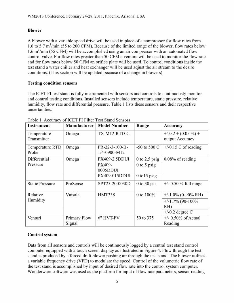
Blower A blower with a variable speed drive will be used in place of a compressor for flow rates from 1.6 to 5.7 m3/min (55 to 200 CFM). Because of the limited range of the blower, flow rates below 1.6 m3/min (55 CFM) will be accomplished using an air compressor with an automated flow control valve. For flow rates greater than 50 CFM a venture will be used to monitor the flow rate and for flow rates below 50 CFM an orifice plate will be used. To control conditions inside the test stand a water chiller and heat exchanger will be used adjust the air stream to the desire conditions. (This section will be updated because of a change in blowers) Testing condition sensors The ICET FI test stand is fully instrumented with sensors and controls to continuously monitor and control testing conditions. Installed sensors include temperature, static pressure, relative humidity, flow rate and differential pressure. Table 1 lists these sensors and their respective uncertainties. Table 1. Accuracy of ICET FI Filter Test Stand Sensors Instrument Manufacturer Model Number Range Accuracy
Temperature Transmitter
Omega TX-M12-RTD-C +/-0.2 + (0.05 %) + output Accuracy
Temperature RTD Probe
Omega PR-22-3-100-B-1/4-0900-M12
-50 to 500 C +/-0.15 C of reading
Differential Pressure
Omega PX409-2.5DDUI 0 to 2.5 psig 0.08% of reading PX409-0005DDUI
0 to 5 psig
PX409-015DDUI 0 to15 psig
Static Pressure ProSense SPT25-20-0030D 0 to 30 psi +/- 0.50 % full range
Relative Humidity
Vaisala HMT338 0 to 100% +/-1.0% (0-90% RH) +/-1.7% (90-100% RH) +/-0.2 degree C
Venturi Primary Flow Signal
6" HVT-FV 50 to 375 +/- 0.50% of Actual Reading
Control system Data from all sensors and controls will be continuously logged by a central test stand control computer equipped with a touch screen display as illustrated in Figure 4. Flow through the test stand is produced by a forced draft blower pushing air through the test stand. The blower utilizes a variable frequency drive (VFD) to modulate the speed. Control of the volumetric flow rate of the test stand is accomplished by input of desired flow rate into the control system computer. Wonderware software was used as the platform for input of flow rate parameters, sensor reading
WM2013 Conference, February 24-28, 2011, Phoenix, Arizona, USA
6
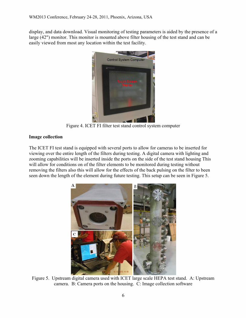
display, and data download. Visual monitoring of testing parameters is aided by the presence of a large (42") monitor. This monitor is mounted above filter housing of the test stand and can be easily viewed from most any location within the test facility.
Figure 4. ICET FI filter test stand control system computer
Image collection The ICET FI test stand is equipped with several ports to allow for cameras to be inserted for viewing over the entire length of the filters during testing. A digital camera with lighting and zooming capabilities will be inserted inside the ports on the side of the test stand housing This will allow for conditions on of the filter elements to be monitored during testing without removing the filters also this will allow for the effects of the back pulsing on the filter to been seen down the length of the element during future testing. This setup can be seen in Figure 5.
Figure 5. Upstream digital camera used with ICET large scale HEPA test stand. A: Upstream
camera. B: Camera ports on the housing. C: Image collection software

WM2013 Conference, February 24-28, 2011, Phoenix, Arizona, USA
7
Data collection During testing conditions inside the test stand will be continuously monitored and recorded using the test control system. This data will include: differential pressure, relative humidity, temperature, static pressure, and volumetric flow rate. Particle concentrations up and downstream of the filter housing will be continuously recorded. These parameters will be monitored and recorded to ensure consistent testing conditions as well as in the data reduction to monitor the effects of changes of multiple parameters on the filtering efficiency. Pressure reducer The higher pressure in the upstream section of the test stand may exceed the capabilities of the aerosol sampling equipment. A pressure reduction device is therefore required at pressures > 1 psig in the upstream airflow for aerosol sampling. The pressure reduction device is used to reduce the pressure in sampling lines to those suitable for instruments used for sampling of the aerosol. This device was designed according to the dimensions from “Design and Performance Evaluation of a Pressure-Reducing Device for Aerosol Sampling from High-Purity Gases”. [13] The pressure reduction device combines an orifice plate with an expansion chamber to reduce the pressure of the sample airstream. The design of the pressure reducer can be seen in Figure 6.
Figure 6. Pressure Reducer
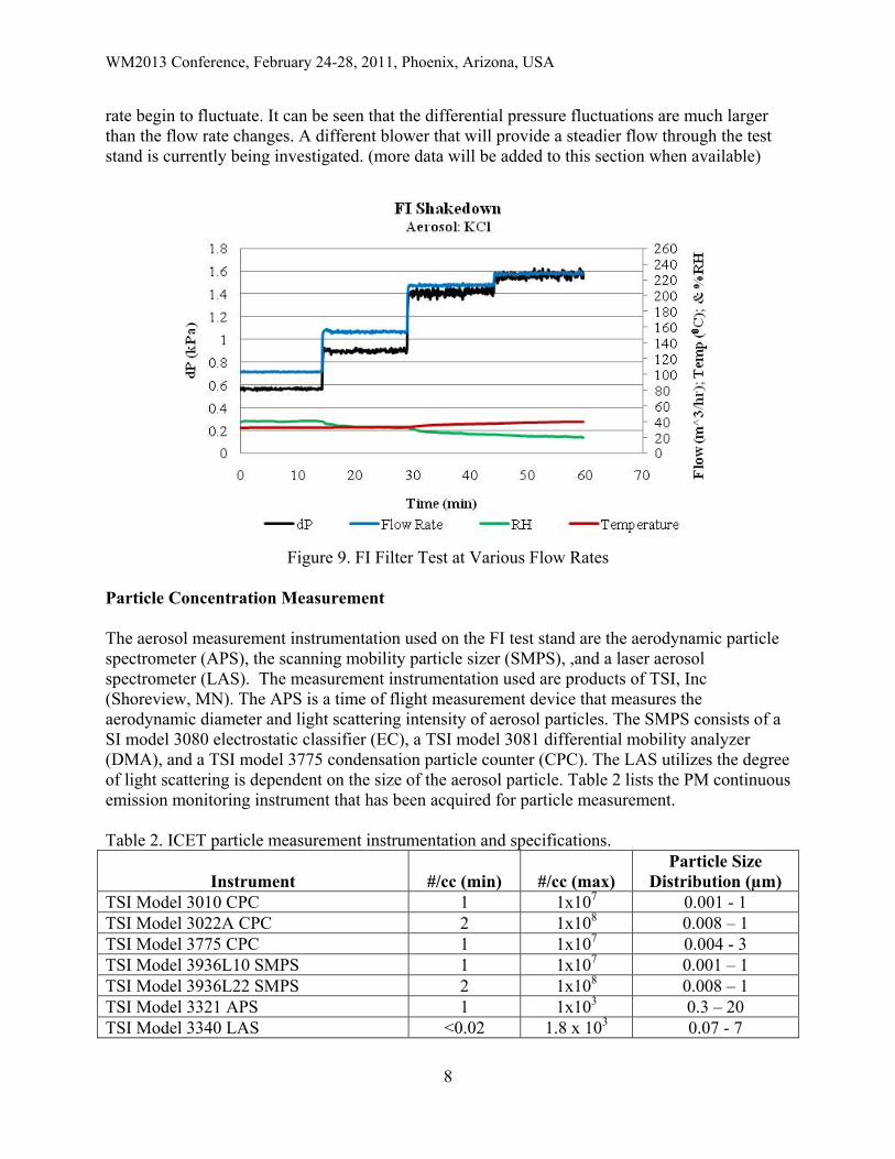
Aerosol neutralization The aerosols generated in this study for filter loading are expected to be highly charged by triboelectric processes during the generation process as dry powder is aerosolized by aspirating dust into injection nozzles. If the particle charges are not neutralized, then the morphology of the particle deposits on the filters will be altered from the deposits with neutral particles and will result in significantly lower pressure drops [14, 15]. To avoid the artificial lowering of the pressure drop in filters due to the charged particle deposits, the aerosols will be neutralized by passing them through a cloud of high concentration positive and negative air ions generated by a radioactive source.. Test stand characterization To ensure accurate data during testing, characterization of the test stand is required. Figure 9 shows the performance of the test stand with clean sintered fiber filters installed at various flow rates. Because of the blower being used as the flow rate increases differential pressure and flow
WM2013 Conference, February 24-28, 2011, Phoenix, Arizona, USA
8
rate begin to fluctuate. It can be seen that the differential pressure fluctuations are much larger than the flow rate changes. A different blower that will provide a steadier flow through the test stand is currently being investigated. (more data will be added to this section when available)
Figure 9. FI Filter Test at Various Flow Rates
Particle Concentration Measurement The aerosol measurement instrumentation used on the FI test stand are the aerodynamic particle spectrometer (APS), the scanning mobility particle sizer (SMPS), ,and a laser aerosol spectrometer (LAS). The measurement instrumentation used are products of TSI, Inc (Shoreview, MN). The APS is a time of flight measurement device that measures the aerodynamic diameter and light scattering intensity of aerosol particles. The SMPS consists of a SI model 3080 electrostatic classifier (EC), a TSI model 3081 differential mobility analyzer (DMA), and a TSI model 3775 condensation particle counter (CPC). The LAS utilizes the degree of light scattering is dependent on the size of the aerosol particle. Table 2 lists the PM continuous emission monitoring instrument that has been acquired for particle measurement. Table 2. ICET particle measurement instrumentation and specifications.
Instrument #/cc (min) #/cc (max) Particle Size
Distribution (µm) TSI Model 3010 CPC 1 1x10⁷ 0.001 - 1 TSI Model 3022A CPC 2 1x10⁸ 0.008 – 1 TSI Model 3775 CPC 1 1x10⁷ 0.004 - 3 TSI Model 3936L10 SMPS 1 1x10⁷ 0.001 – 1 TSI Model 3936L22 SMPS 2 1x10⁸ 0.008 – 1 TSI Model 3321 APS 1 1x10³ 0.3 – 20 TSI Model 3340 LAS <0.02 1.8 x 10³ 0.07 - 7

WM2013 Conference, February 24-28, 2011, Phoenix, Arizona, USA
9
Aerosol The challenge aerosol used in this testing is Potassium Chloride (KCl). The Potassium Chloride aerosol particle size distribution in logarithmic scale can be seen in figure 7.
Figure 7. Upstream Particle Size Distribution Shakedown Testing
Representative FI Radial Flow HEPA Filter A set of filter elements attached to the tube sheet are shown on ready for insertion into the test stand housing are shown in Figure 8.
Figure 8. Representative Section FI HEPA Filter Elements

WM2013 Conference, February 24-28, 2011, Phoenix, Arizona, USA
10
Testing The test filter elements were tested at 130 CFM under ambient conditions. Testing thus far has only been on sintered fiber filters in the future data for sintered powder filters will be collected and compared to the sintered fiber filters. Table 3 shows the filter testing conditions. Table 3. Filter and Testing Parameters Filter Filter Type and Testing Parameters and guidelines Aerosol
POR-F-001 Porvair Sintered Fiber Pleated Filter 221 m3/hr
16 to 27º C 40 to 60% RH
Potassium Chloride
MO-P-001 Mott Sintered Powder Filter
Discussion Sintered Metal fiber filters were tested under rated air flow and twenty percent of rated air flow conditions for resistance to pressure, resistance to air flow, and resistance to test aerosol penetration. Raw data collected during these tests was reduced into the form of graphical data to be able to easily show the behavior of these filters. So far only one set of filters provided by Porvair Filtration. The filters provided by Porvair Filtration have a length of 1 meter, diameter of 8 centimeters, pleated construction and constructed of sintered metal fiber. Test conditions The test conditions can affect the performance of a filter. The test conditions for the filters tested are monitored and displayed graphically to be able to compare any irregularities of the performance of the filter to changes in conditions that could have caused these irregularities. This graphical representation can also show how the differential pressure will increase over time during loading. The blower used during these tests causes oscillations in the flow which also can be seen in the differential pressure across the filter. The raising in temperature over the course of the test is due to the heating from compression as well as heat added from the aerosol generator. A chiller and heat exchanger will be connected inline with the blower to bring the temperature within the allowed range. The test conditions versus time for the filter test can be seen in figure 9.

WM2013 Conference, February 24-28, 2011, Phoenix, Arizona, USA
11
Figure 10. FI Filter Testing Conditions for FE Testing
Upstream particle size distribution The upstream particle size distribution (PSD) plot is made using data from both the SMPS and APS. Because of the particle size limitations on each instrument it is necessary to combine the particle counts from each to cover the desired particle diameter range. Because of the use of different instruments the graphical representation of the upstream particle size distribution is not lined up perfectly but the overall curve can be seen. The PSD graph is created using the average counts over the length of the test. The upstream PSD can be seen in figure 11.
Figure 11. Upstream Particle Size Distribution for FE Testing
Downstream particle size distribution The downstream particle size distribution used particle counts from the LAS. The data collected from the LAS was averaged over the length of the test and plotted. This plot can be seen in figure 12. This data combined with the upstream particle size distribution is used for the penetration

WM2013 Conference, February 24-28, 2011, Phoenix, Arizona, USA
12
curve. Because of the low particle count in the downstream section the particle size distribution curve is not smooth in some places.
Figure 12. Downstream Particle Size Distribution for FE Testing
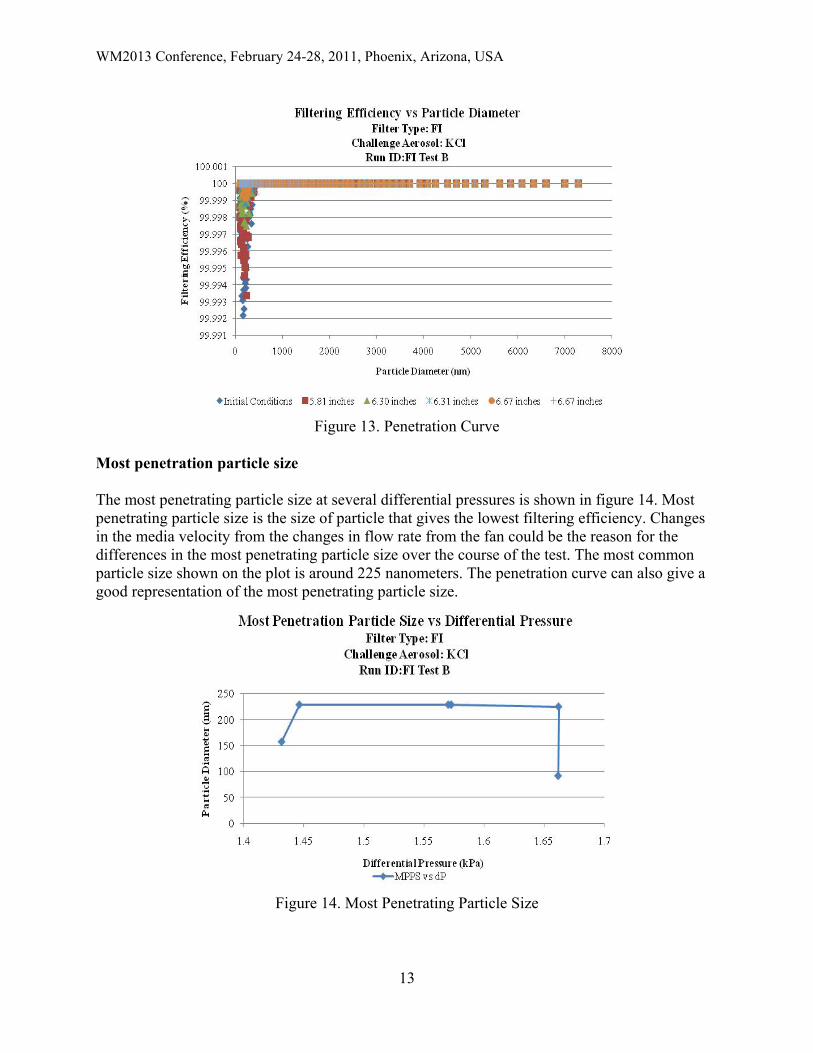
Penetration curve The filtering efficiency versus particle diameter curve also known as the penetration curve is a direct comparison of the upstream and downstream particle size distributions to see how the filter performs against different particle sizes. The penetration curve helps to identify the most penetration particle size. The most penetration particle size can easily be seen on the penetration curve. The penetration curve displays the filtering efficiency at several different points during the test. The lowest filtering efficiency for any particle matter these test elements occurs when the filter is clean and is greater than 99.992%. The penetration curve can be seen in figure 13.
WM2013 Conference, February 24-28, 2011, Phoenix, Arizona, USA
13
Figure 13. Penetration Curve
Most penetration particle size The most penetrating particle size at several differential pressures is shown in figure 14. Most penetrating particle size is the size of particle that gives the lowest filtering efficiency. Changes in the media velocity from the changes in flow rate from the fan could be the reason for the differences in the most penetrating particle size over the course of the test. The most common particle size shown on the plot is around 225 nanometers. The penetration curve can also give a good representation of the most penetrating particle size.
Figure 14. Most Penetrating Particle Size
WM2013 Conference, February 24-28, 2011, Phoenix, Arizona, USA
14
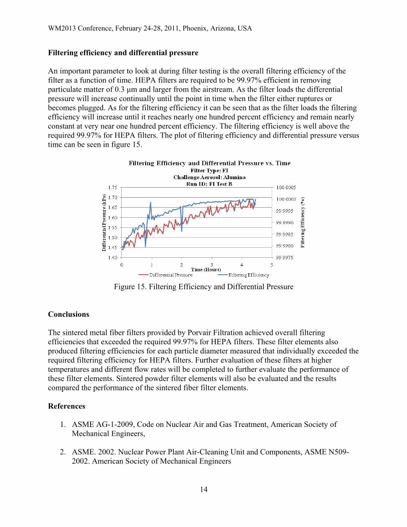
Filtering efficiency and differential pressure An important parameter to look at during filter testing is the overall filtering efficiency of the filter as a function of time. HEPA filters are required to be 99.97% efficient in removing particulate matter of 0.3 μm and larger from the airstream. As the filter loads the differential pressure will increase continually until the point in time when the filter either ruptures or becomes plugged. As for the filtering efficiency it can be seen that as the filter loads the filtering efficiency will increase until it reaches nearly one hundred percent efficiency and remain nearly constant at very near one hundred percent efficiency. The filtering efficiency is well above the required 99.97% for HEPA filters. The plot of filtering efficiency and differential pressure versus time can be seen in figure 15.
Figure 15. Filtering Efficiency and Differential Pressure
Conclusions The sintered metal fiber filters provided by Porvair Filtration achieved overall filtering efficiencies that exceeded the required 99.97% for HEPA filters. These filter elements also produced filtering efficiencies for each particle diameter measured that individually exceeded the required filtering efficiency for HEPA filters. Further evaluation of these filters at higher temperatures and different flow rates will be completed to further evaluate the performance of these filter elements. Sintered powder filter elements will also be evaluated and the results compared the performance of the sintered fiber filter elements. References
1. ASME AG-1-2009, Code on Nuclear Air and Gas Treatment, American Society of Mechanical Engineers,
2. ASME. 2002. Nuclear Power Plant Air-Cleaning Unit and Components, ASME N509-
2002. American Society of Mechanical Engineers

WM2013 Conference, February 24-28, 2011, Phoenix, Arizona, USA
15
3. ASME. 1989. Testing of Nuclear Air Treatment Systems, ASME N510-1989. American Society of Mechanical Engineers
4. ASME N511 In-Service Testing of Nuclear Air Treatment, Heating, Ventilating, and Air-
Conditioning Systems, 2007
5. Rubow, Kenneth. Louise L. Strange, Billy Huang. Advances in Filtration Technology Using Sintered Metal Filters. 3rd China International Filtration Exhibition and Conference. Shanghai, China, November 2004.
6. “HEPA Filters Used in the Department of Energy’s Hazardous Facilities”; Defense
Nuclear Facilities Safety Board; DNFSB/TECH-23, May (1999).
7. http://www.dnfsb.gov/pub_docs/recommendations/all/rec_2000_02.pdf
8. “A Report and Action Plan in Response to Defense Nuclear Facilities Safety Board Technical Report 23,” Department of Energy (DOE), December (1999).
9. L.D. Weber. “Emerging ASME AG-1 Code: Article FI, On Metal Medium Filters.” 25th
Nuclear Air Cleaning and Treatment Conference, (1998)
10. Duane J. Adamson and Charles A. Waggoner. “Development of AG-1 Section FI on Metal Media Filters – 9061.” WM2009 Conference, March 1-5, Phoenix, AZ, (2009)
11. W. Bergman et.al. “Further Development of the Cleanable Steel HEPA Filter,
Cost/Benefit Analysis and Comparison with Competing Technologies.” 24th Nuclear Air Cleaning and Treatment Conference, (1996).
12. Rubow, Kenneth “Porous Metal Filters for Gas and Liquid Applications in the Nuclear Industry” Mott Corporation. WM2009 Conference, March 1-5, 2009, Phoenix, AZ
13. Lee, Jae-Keun, Kenneth L. Rubow, David Y. H. Pui, and Benjamin Y. H. Liu. “Design
and Performance Evaluation of a Pressure-Reducing Device for Aerosol Sampling from High-Purity Gases” . Aerosol Science and Technology 19: 215-226 (1993).
14. Endo, Y., Chen, D.R. and Pui, DYH, “Bimodal Aerosol Loading and Dust Cake
Formation on Air Filters”, Filtration and Separation, March 1998, pp. 191-195
15. D. Loughborough, “The Dust Holding Capacity of HEPA Filters”, 21st DOE/NRC Nuclear Air Cleaning Conference