Embed Size (px)
Citation preview
DYNAMIC FORCE ANALYSIS
If the acceleration of moving links in a mechanism are running with considerable amount of
linear and/or angular accelerations, inertia forces are generated and these inertia forces also
must be overcome by the driving motor as an addition to the forces exerted by the external
load or work the mechanism does. So, 0=∑Fv
and 0=∑ τv
are no longer applicable.
Governing rules will be:
aFvv
m=∑
ατvv
I=∑
I and m are inertial (bodily) properties. At this stage we need to know the description of the
inertial properties.
Centroid and Mass Centre
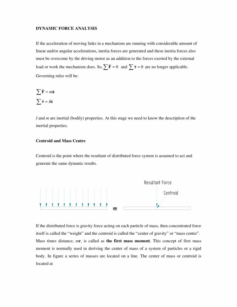
Centroid is the point where the resultant of distributed force system is assumed to act and
generate the same dynamic results.
Centroid
Resultant Force
If the distributed force is gravity force acting on each particle of mass, then concentrated force
itself is called the “weight” and the centroid is called the “center of gravity” or “mass center”.
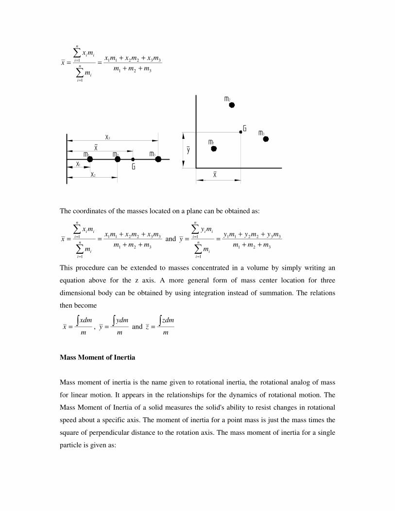
Mass times distance, mr, is called as the first mass moment. This concept of first mass
moment is normally used in deriving the center of mass of a system of particles or a rigid
body. In figure a series of masses are located on a line. The center of mass or centroid is
located at
321
332211
1
1
mmm
mxmxmx
m
mx
xn
i
i
n
i
ii
++
++==
∑
∑
=
=
x3
x1x2
x-m1 m2 m3
G
m1
m2
m3
x-
y-
G
The coordinates of the masses located on a plane can be obtained as:
321
332211
1
1
mmm
mxmxmx
m
mx
xn
i
i
n
i
ii
++
++==
∑
∑
=
= and 321
332211
1
1
mmm
mymymy
m
my
yn
i
i
n
i
ii
++
++==
∑
∑
=
=
This procedure can be extended to masses concentrated in a volume by simply writing an
equation above for the z axis. A more general form of mass center location for three
dimensional body can be obtained by using integration instead of summation. The relations
then become
m
xdmx∫= ,
m
ydmy∫= and
m
zdmz∫=
Mass Moment of Inertia
Mass moment of inertia is the name given to rotational inertia, the rotational analog of mass
for linear motion. It appears in the relationships for the dynamics of rotational motion. The
Mass Moment of Inertia of a solid measures the solid's ability to resist changes in rotational
speed about a specific axis. The moment of inertia for a point mass is just the mass times the
square of perpendicular distance to the rotation axis. The mass moment of inertia for a single
particle is given as:
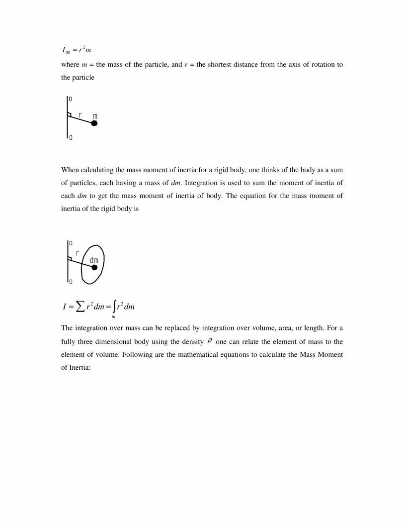
mrI2
00 =
where m = the mass of the particle, and r = the shortest distance from the axis of rotation to
the particle
r
o
o
m
When calculating the mass moment of inertia for a rigid body, one thinks of the body as a sum
of particles, each having a mass of dm. Integration is used to sum the moment of inertia of
each dm to get the mass moment of inertia of body. The equation for the mass moment of
inertia of the rigid body is
r
o
o
dm
I r dm r dmm
= =∑ ∫2 2
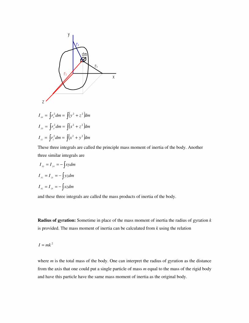
The integration over mass can be replaced by integration over volume, area, or length. For a
fully three dimensional body using the density ρ one can relate the element of mass to the
element of volume. Following are the mathematical equations to calculate the Mass Moment
of Inertia:
x
y
dm
z
rz
ry
rx
( )dmzydmrI xxx ∫ ∫ +== 222
( )dmzxdmrI yyy ∫ ∫ +== 222
( )dmyxdmrI zzz ∫ ∫ +== 222
These three integrals are called the principle mass moment of inertia of the body. Another
three similar integrals are
∫−== xydmII yxxy
∫−== yzdmII zyyz
∫−== xzdmII zxxz
and these three integrals are called the mass products of inertia of the body.
Radius of gyration: Sometime in place of the mass moment of inertia the radius of gyration k
is provided. The mass moment of inertia can be calculated from k using the relation
2mkI =
where m is the total mass of the body. One can interpret the radius of gyration as the distance
from the axis that one could put a single particle of mass m equal to the mass of the rigid body
and have this particle have the same mass moment of inertia as the original body.
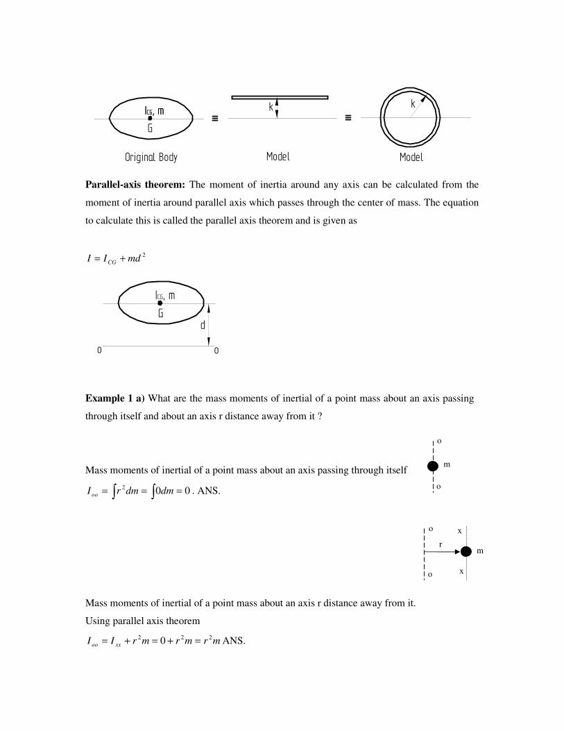
G
ICG, m kICG, mk
Original Body Model Model
Parallel-axis theorem: The moment of inertia around any axis can be calculated from the
moment of inertia around parallel axis which passes through the center of mass. The equation
to calculate this is called the parallel axis theorem and is given as
2mdII CG +=
Gd
ICG, m
o o
Example 1 a) What are the mass moments of inertial of a point mass about an axis passing
through itself and about an axis r distance away from it ?
Mass moments of inertial of a point mass about an axis passing through itself
∫ ∫ === 002dmdmrI oo . ANS.
Mass moments of inertial of a point mass about an axis r distance away from it.
Using parallel axis theorem
mrmrmrII xxoo
222 0 =+=+= ANS.
o
o
m
o
o
r m
x
x
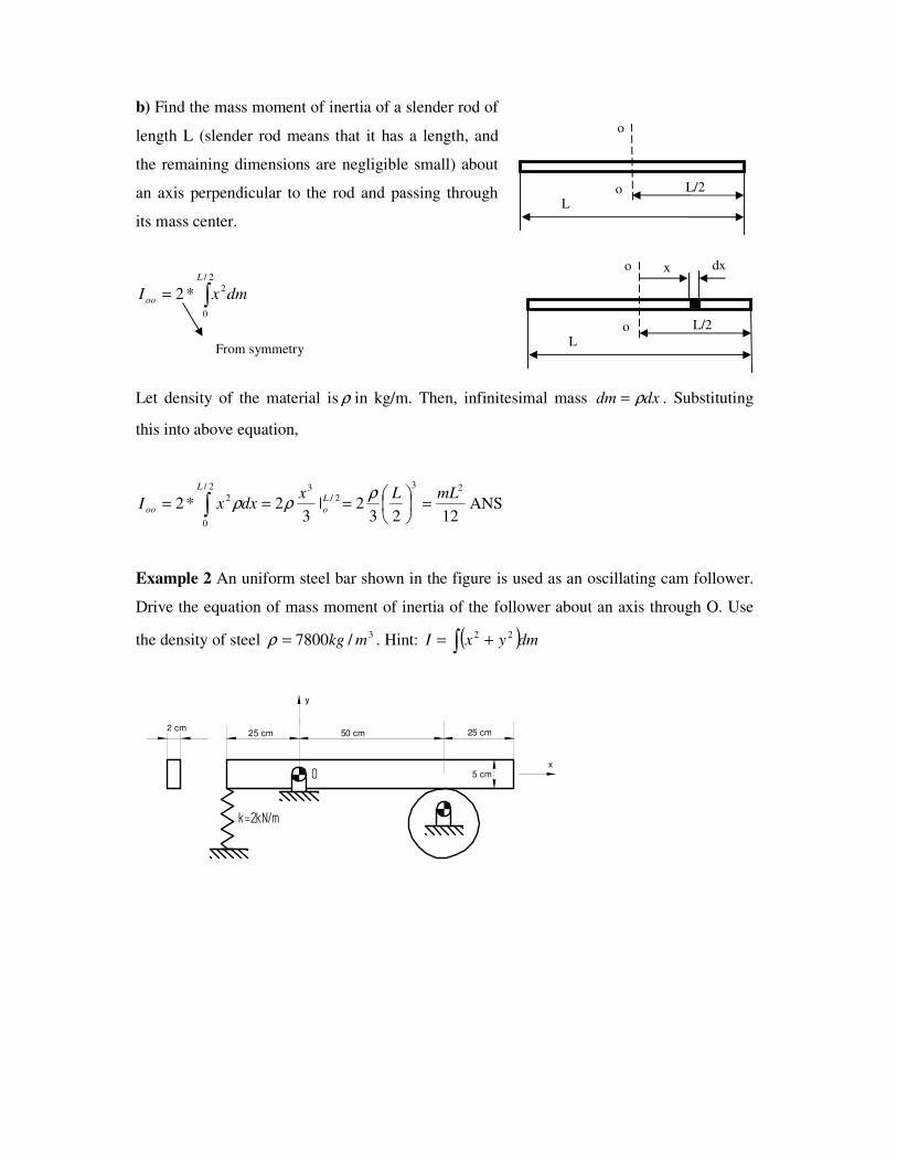
b) Find the mass moment of inertia of a slender rod of
length L (slender rod means that it has a length, and
the remaining dimensions are negligible small) about
an axis perpendicular to the rod and passing through
its mass center.
∫=2/
0
2*2
L
oo dmxI
Let density of the material is ρ in kg/m. Then, infinitesimal mass dxdm ρ= . Substituting
this into above equation,
12232|
32*2
23
2/
2/
0
32 mLLx
dxxIL
o
L
oo =
=== ∫ρ
ρρ ANS
Example 2 An uniform steel bar shown in the figure is used as an oscillating cam follower.
Drive the equation of mass moment of inertia of the follower about an axis through O. Use
the density of steel 3/7800 mkg=ρ . Hint: ( )dmyxI ∫ += 22
k=2kN/m
2 cm25 cm 50 cm 25 cm
5 cm
y
x
O
L
L/2
o
o
L
L/2
o
o
dx x
From symmetry
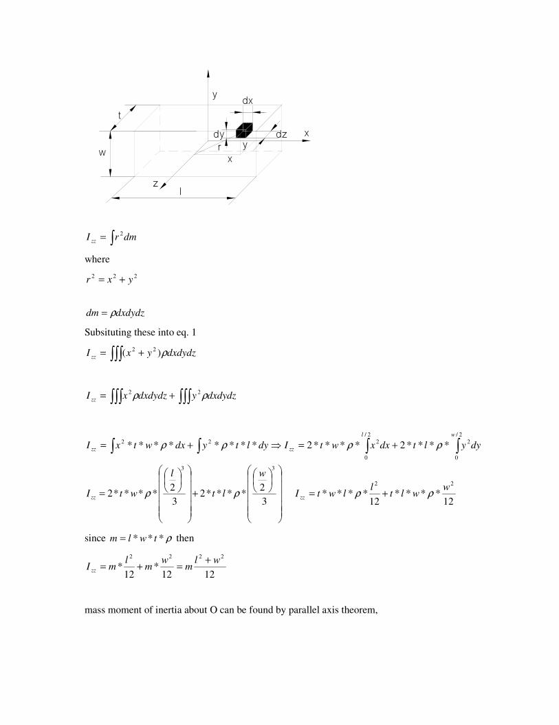
x
y
z
xyr
dx
dzdy
t
w
l
∫= dmrI zz
2
where
dxdydzdm ρ=
Subsituting these into eq. 1
∫∫∫ += dxdydzyxI zz ρ)( 22
∫∫∫∫∫∫ += dxdydzydxdydzxI zz ρρ 22
∫∫∫∫ +=⇒+=2/
0
2
2/
0
222****2****2********
wl
zzzz dyyltdxxwtIdyltydxwtxI ρρρρ
+
=3
2****2
3
2****2
33w
lt
l
wtI zz ρρ 12
****12
****22
wwlt
llwtI zz ρρ +=
since ρ*** twlm = then
1212*
12*
2222wl
mw
ml
mI zz
+=+=
mass moment of inertia about O can be found by parallel axis theorem,
222 yxr +=
48
47
412*
22
2
2222
0
wlm
lm
wlmdmII zz
+=+
+=+= , kgm 8.702.0*05.0*1*7800 == and
mkgI .139.148
05.0*41*78.7
22
0 =+
=
D’Alembert’s Principle:
D’Alembert’s principle permits the reduction of a problem in dynamics to one in statics. This
is accomplished by introducing a fictitious force equal in magnitude to the product of the
mass of the body and its acceleration, and directed opposite to the acceleration. The result is a
condition of kinetic equilibrium. If we subtract a vector of magnitude av
m− from both sides of
the Newton’s second law. The meaning of the equation; i.e. indication of a dynamic case still
holds true, but equation, having zero on right hand side becomes very easy to solve, like that
in a “static force analysis” problem.
0=−=−∑ aaaFvvvv
mmm and similarly for moment
0=−=−∑ ααατvvvv
mmm
Solution of a dynamic problem using D’Alembert’s principle
i) Do an acceleration analysis and calculate the linear acceleration of the mass
centers of each moving link. Also calculate the angular acceleration of each
moving link.
ii) Masses and centroidal inertias of each moving link must be known beforehand.
iii) Add one fictitious force on each moving body equal to the mass of that body times
the acceleration of its mass center, direction opposite to its acceleration, applied
directly onto the center of gravity, apart from the already existing real forces.
iv) Add fictitious torque on each moving body equal to the centroidal inertia of that
body times its angular acceleration, direction or sense opposite to that of
acceleration apart from the already existing real torques.
v) Solve statically.
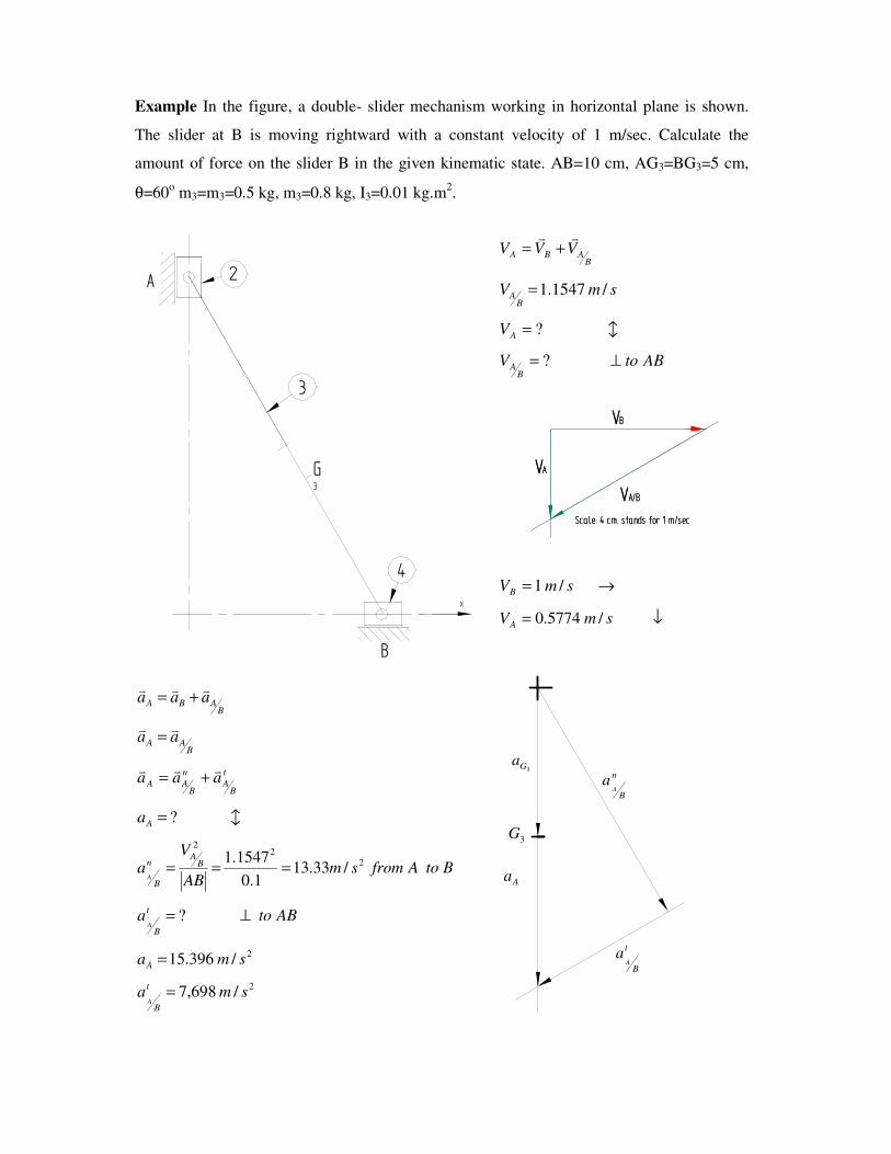
Example In the figure, a double- slider mechanism working in horizontal plane is shown.
The slider at B is moving rightward with a constant velocity of 1 m/sec. Calculate the
amount of force on the slider B in the given kinematic state. AB=10 cm, AG3=BG3=5 cm,
θ=60o m3=m3=0.5 kg, m3=0.8 kg, I3=0.01 kg.m
2.
BABA VVVvv
+=
smVB
A /1547.1=
b?=AV
ABtoVB
A ⊥= ?
→= smVB /1
↓= smVA /5774.0
BABA aaavvv
+=
BAA aavv
=
t
BA
n
BAA aaa
vvv+=
b?=Aa
BtoAfromsmAB
Va B
An
BA
22
2
/33.131.0
1547.1===
ABtoat
BA
⊥= ?
2/396.15 smaA =
2/698,7 smat
BA
=
4
B
2A
3
G3
x
VB
VA/B
VA
Scale: 4 cm. stands for 1 m/sec
VB
VA/B
VA
Scale: 4 cm. stands for 1 m/sec
n
BA
a
t
BA
a
Aa
3Ga
3G
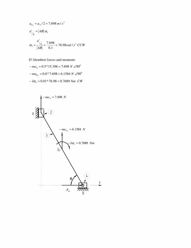
2/698.72/
3smaa AG ==
3αABat
BA
=
CCWsradAB
at
BA
2
3 /98.781.0
698.7===α
D’Alembert forces and moments
090698.7396.15*5.0 ∠==− NmaA
0901584.6698.7*8.03
∠==− NmaG
CWNmI 7689.098.76*01.03 ==− α
4
B
2A
3
G3
xθ
NmaG 1584.63
=−
Nma A 698.7=−
NmI 7689.03 =− α
BF
4
B
2A
3
G3
x
θ
N1584.6
N698.7
Nm7689.0
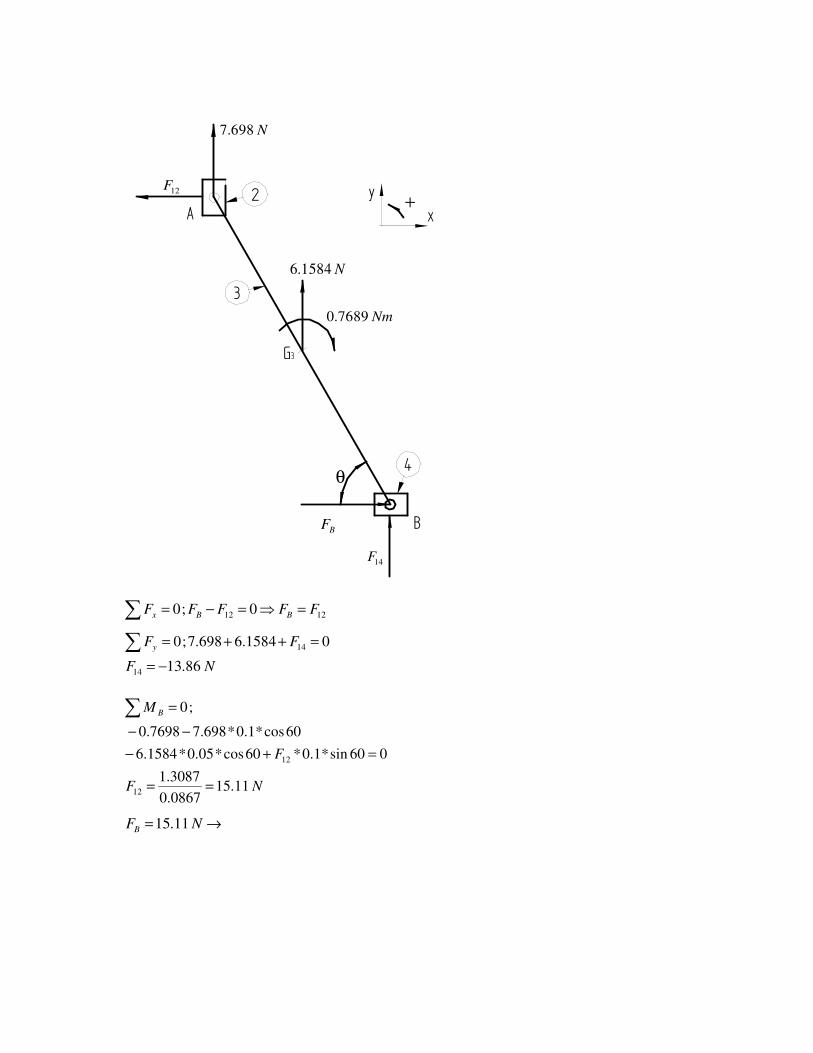
BF
y +
14F
12F
∑ =⇒=−= 1212 0;0 FFFFF BBx
NF
FFy
86.13
01584.6698.7;0
14
14
−=
=++=∑
NF
F
M B
11.150867.0
3087.1
060sin*1.0*60cos*05.0*1584.6
60cos*1.0*698.77698.0
;0
12
12
==
=+−
−−
=∑
→= NFB 11.15
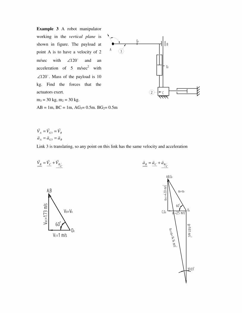
Example 3 A robot manipulator
working in the vertical plane is
shown in figure. The payload at
point A is to have a velocity of 2
m/sec with o120∠ and an
acceleration of 5 m/sec2 with
o120∠ . Mass of the payload is 10
kg. Find the forces that the
actuators exert.
m3 = 30 kg, m2 = 30 kg.
AB = 1m, BC = 1m, AG3= 0.5m. BG2= 0.5m
BGA
BGA
aaa
VVVvvv
vvv
==
==
3
3
Link 3 is translating, so any point on this link has the same velocity and acceleration
CBCB VVVvvv
+= C
BCB aaavvv
+=
2
3
G3
G2
AB
C
VB=VA
VC=1 m/s
VB/C=1.73 m/s
A,B
OV60
o
aB=aA
aC=2.5 m/s
aB/C=4.33 m/s
A,B,G3
Oa60
o
C,G2 2
2
g=9.81 m/s 2
aG3=a
A=14.14 m/s 2
10.03o
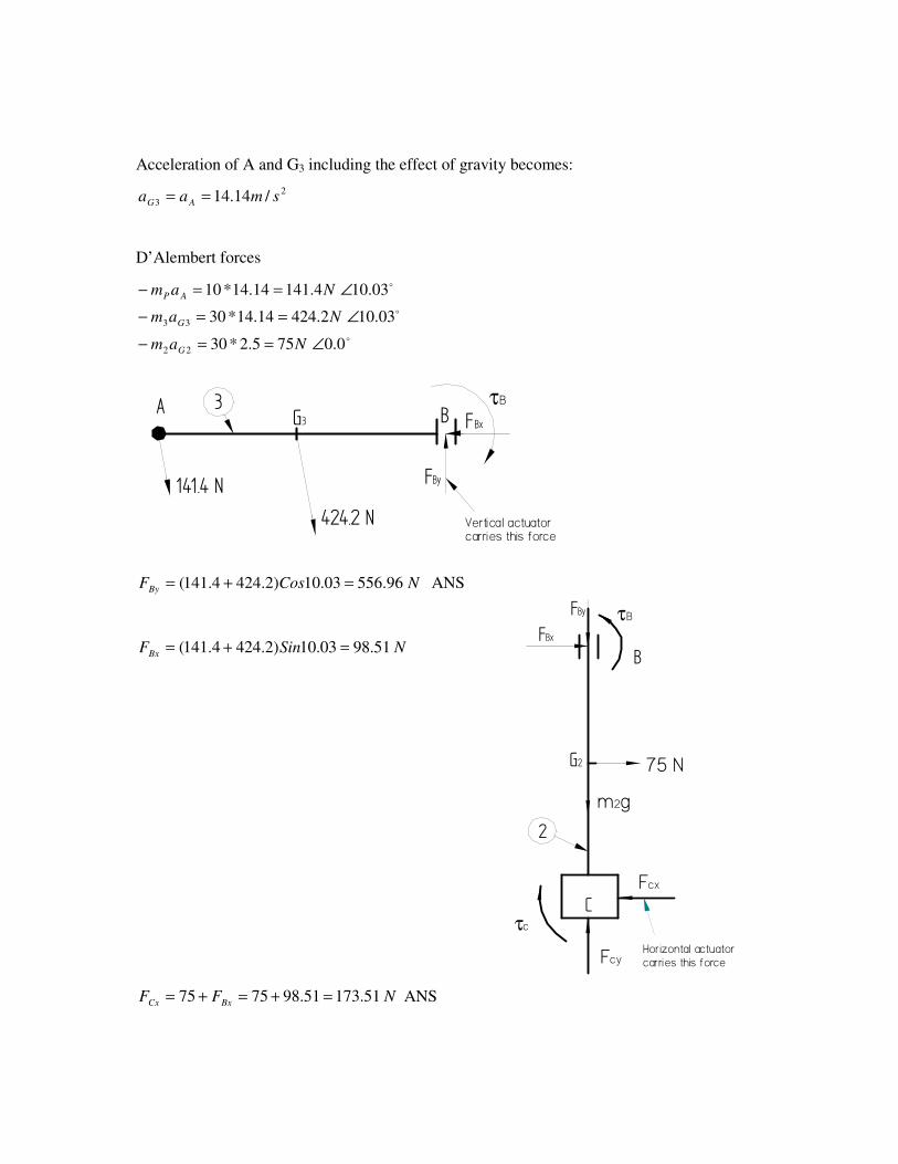
Acceleration of A and G3 including the effect of gravity becomes:
2
3 /14.14 smaa AG ==
D’Alembert forces
o
o
o
0.0755.2*30
03.102.42414.14*30
03.104.14114.14*10
22
33
∠==−
∠==−
∠==−
Nam
Nam
Nam
G
G
AP
3G3A B FBx
FBy
424.2 N
141.4 N
τB
Vertical actuatorcarries this force
NCosFBy 96.55603.10)2.4244.141( =+= ANS
NSinFBx 51.9803.10)2.4244.141( =+=
NFF BxCx 51.17351.987575 =+=+= ANS
2
G2
B
C
75 N
m2g
Fcx
Fcy
τc
τBFBx
FBy
Horizontal actuatorcarries this force
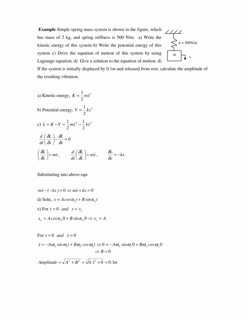
Example Simple spring mass system is shown in the figure, which
has mass of 2 kg, and spring stiffness is 500 N/m. a) Write the
kinetic energy of this system b) Write the potential energy of this
system c) Drive the equation of motion of this system by using
Lagrange equation. d) Give a solution to the equation of motion. d)
If the system is initially displaced by 0.1m and released from rest, calculate the amplitude of
the resulting vibration.
a) Kinetic energy, 2
2
1xmK &=
b) Potential energy, 2
2
1kxV =
c) 22
2
1
2
1kxxmVKL −=−= &
0=−
x
L
x
L
dt
d
δδ
δδ&
xmx
L&
&=
δδ
, xmx
L
dt
d&&
&=
δδ
, kxx
L−=
δδ
Substituting into above eqn
00 =+⇒=−− kxxm)kx(xm &&&&
d) Soln, tsinBtcosAx nn ωω +=
e) For oxxandt == 0
AxsinBcosAx onno =⇒+= 00 ωω
For 00 == xandt &
0
000
=⇒
+−=⇒+−=
B
cosBsinAtcosBtsinAx nnnnnnnn ωωωωωωωω&
m..BAAmplitude 10010 222 =+=+=
m
k = 500N/m
x
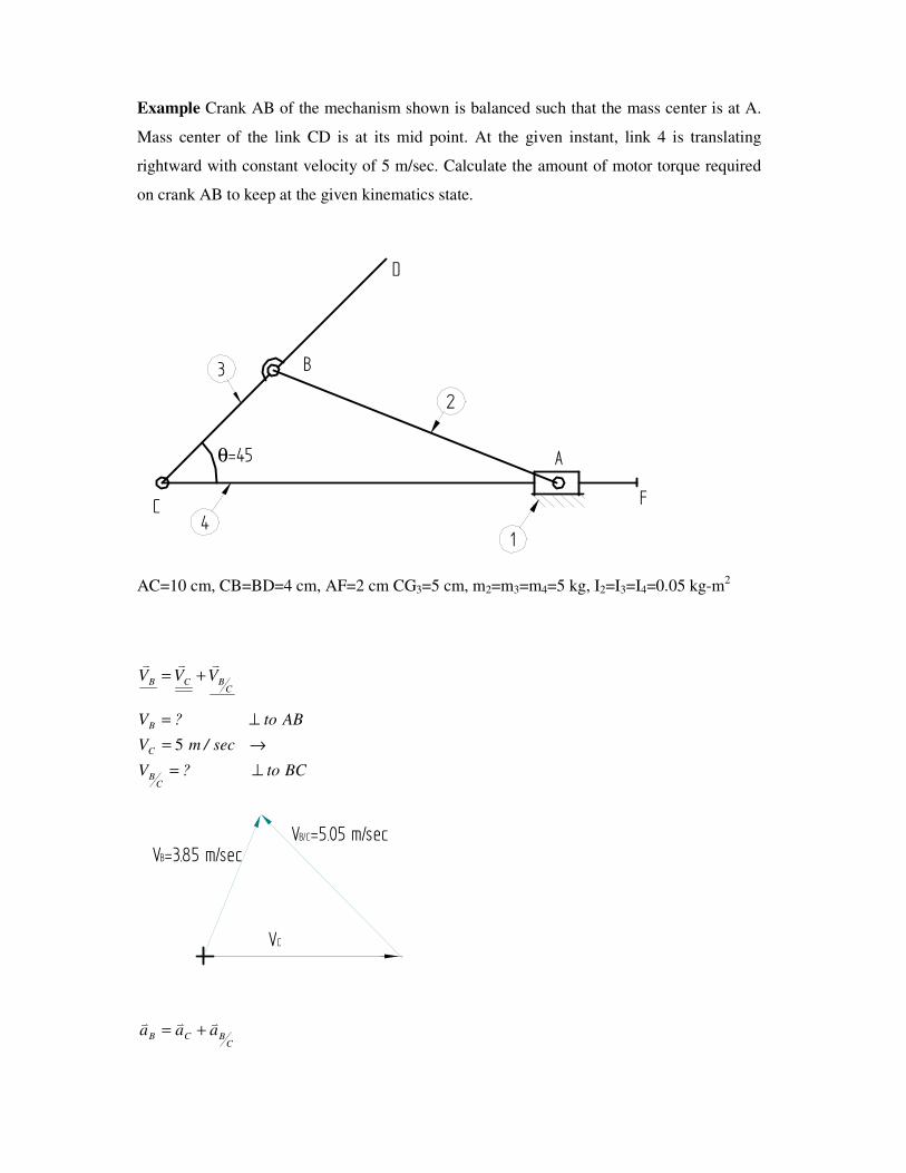
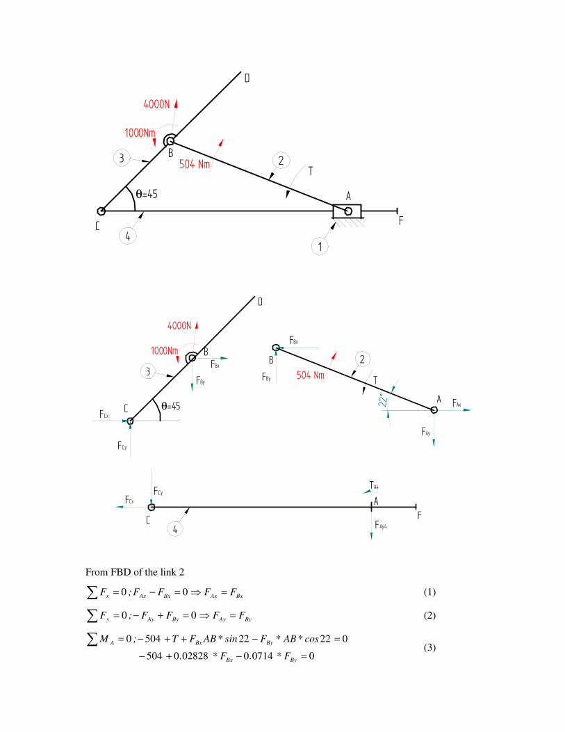
Example Crank AB of the mechanism shown is balanced such that the mass center is at A.
Mass center of the link CD is at its mid point. At the given instant, link 4 is translating
rightward with constant velocity of 5 m/sec. Calculate the amount of motor torque required
on crank AB to keep at the given kinematics state.
14
2
3
A
C
B
D
θ=45
F
AC=10 cm, CB=BD=4 cm, AF=2 cm CG3=5 cm, m2=m3=m4=5 kg, I2=I3=I4=0.05 kg-m2
CBCB VVVvvv
+=
BCto?V
sec/mV
ABto?V
CB
C
B
⊥=
→=
⊥=
5
VC
VB=3.85 m/secVB/C=5.05 m/sec
CBCB aaavvv
+=
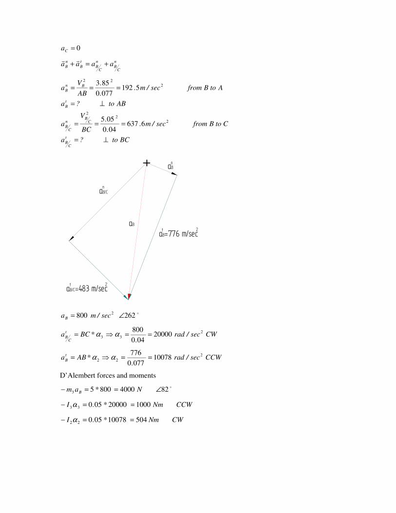
0=Ca
n
CB
n
CB
t
B
n
B aaaa +=+vv
BCto?a
CtoBfromsec/m..
.
BC
Va
ABto?a
AtoBfromsec/m..
.
AB
Va
t
CB
CB
n
CB
t
B
Bn
B
⊥=
===
⊥=
===
22
2
222
6637040
055
51920770
853
aB=776 m/sec
aB/C=483 m/sect 2
2t
aBn
aB/Cn
aB
o262800 2 ∠= sec/maB
CWsec/rad.
*BCat
CB
2
33 20000040
800==⇒= αα
CCWsec/rad.
*ABat
B
2
22 100780770
776==⇒= αα
D’Alembert forces and moments
o82400080053 ∠==− N*am B
CCWNm*.I 10002000005033 ==− α
CWNm*.I 5041007805022 ==− α
14
23
A
C
B
D
θ=45
F
504 Nm
1000Nm
T
4000N
4
23
A
C
B
D
θ=45
F
T
FAy
FBy
C
B
AFCx
FCy TA4
504 Nm
1000Nm
4000N
FCx
FCy
FBxFBy
FBx
FAx
FAy4
22°
From FBD of the link 2
∑ =⇒=−= BxAxBxAxx FFFF;F 00 (1)
∑ =⇒=+−= ByAyByAyy FFFF;F 00 (2)
007140028280504
022225040
=−+−
=−++−=∑ByBx
ByBxA
F*.F*.
cos*AB*Fsin*ABFT;M (3)
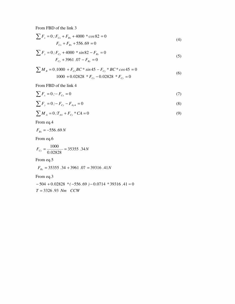
From FBD of the link 3
069556
08240000
=++
=++=∑.FF
cos*FF;F
BxCx
BxCxx (4)
0073961
08240000
=−+
=−+=∑ByCy
ByCyy
F.F
Fsin*F;F (5)
00282800282801000
0454510000
=−+
=−+=∑CyCx
CyCxB
F*.F*.
cos*BC*Fsin*BCF;M (6)
From FBD of the link 4
∑ =−= 00 Cxx F;F (7)
∑ =−−= 00 4AyCyy FF;F (8)
∑ =+= 00 4 CA*FT;M CyAA (9)
From eq.4
N.FBx 69556−=
From eq.6
N..
FCy 3435355028280
1000==
From eq.5
N...FBy 41393160739613435355 =+=
From eq.3
CCWNm.T
.*.).(*.
933326
041393160714069556028280504
=
=−−+−
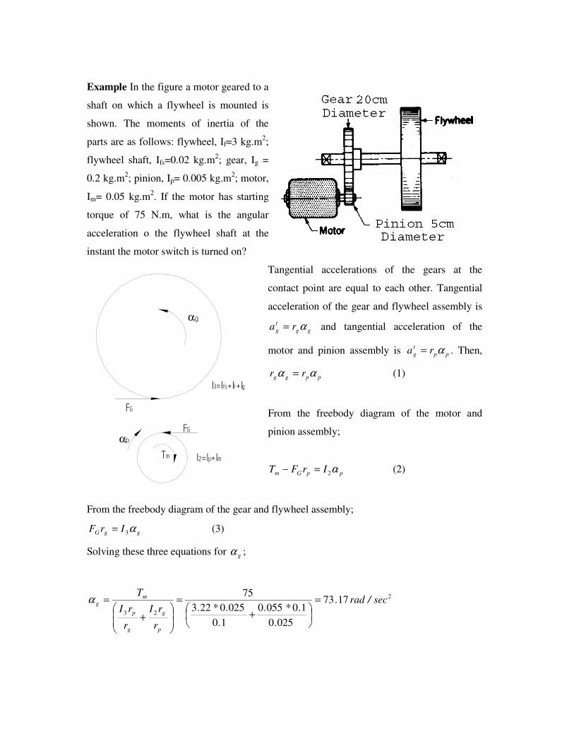
Example In the figure a motor geared to a
shaft on which a flywheel is mounted is
shown. The moments of inertia of the
parts are as follows: flywheel, If=3 kg.m2;
flywheel shaft, Ifs=0.02 kg.m2; gear, Ig =
0.2 kg.m2; pinion, Ip= 0.005 kg.m
2; motor,
Im= 0.05 kg.m2. If the motor has starting
torque of 75 N.m, what is the angular
acceleration o the flywheel shaft at the
instant the motor switch is turned on?
Tangential accelerations of the gears at the
contact point are equal to each other. Tangential
acceleration of the gear and flywheel assembly is
gg
t
g ra α= and tangential acceleration of the
motor and pinion assembly is pp
t
g ra α= . Then,
ppgg rr αα = (1)
From the freebody diagram of the motor and
pinion assembly;
ppGm IrFT α2=− (2)
From the freebody diagram of the gear and flywheel assembly;
ggG IrF α3= (3)
Solving these three equations for gα ;
2
23
1773
0250
100550
10
0250223
75sec/rad.
.
.*.
.
.*.
r
rI
r
rI
T
p
g
g
p
m
g =
+=
+
=α
Tm
FG
FG
I2=Ip+Im
I3=Ifs+If+Ig
αp
αg
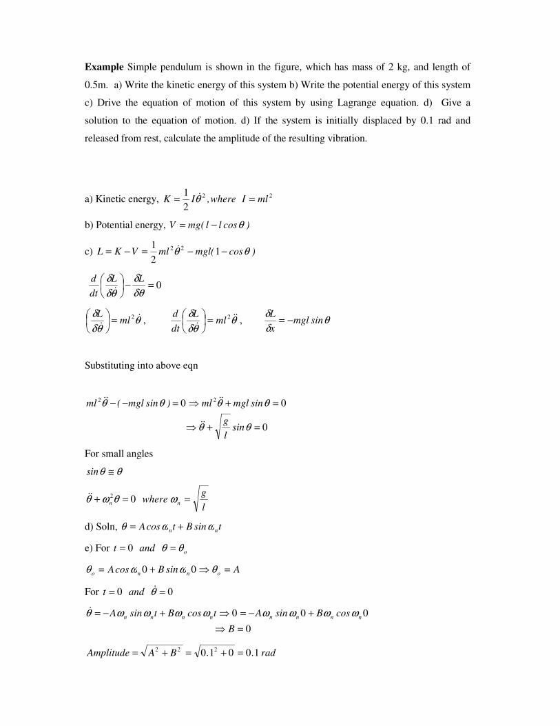
Example Simple pendulum is shown in the figure, which has mass of 2 kg, and length of
0.5m. a) Write the kinetic energy of this system b) Write the potential energy of this system
c) Drive the equation of motion of this system by using Lagrange equation. d) Give a
solution to the equation of motion. d) If the system is initially displaced by 0.1 rad and
released from rest, calculate the amplitude of the resulting vibration.
a) Kinetic energy, 22
2
1mlIwhere,IK == θ&
b) Potential energy, )cosll(mgV θ−=
c) )cos(mglmlVKL θθ −−=−= 12
1 22 &
0=−
δθδ
θδδ LL
dt
d
&
θθδ
δ &&
2ml
L=
, θ
θδδ &&&
2ml
L
dt
d=
, θ
δδ
sinmglx
L−=
Substituting into above eqn
0
00 22
=+⇒
=+⇒=−−
θθ
θθθθ
sinl
g
sinmglml)sinmgl(ml
&&
&&&&
For small angles
θθ ≅sin
l
gwhere nn ==+ ωθωθ 02&&
d) Soln, tsinBtcosA nn ωωθ +=
e) For oandt θθ == 0
AsinBcosA onno =⇒+= θωωθ 00
For 00 == θ&andt
0
000
=⇒
+−=⇒+−=
B
cosBsinAtcosBtsinA nnnnnnnn ωωωωωωωωθ&
rad..BAAmplitude 10010 222 =+=+=
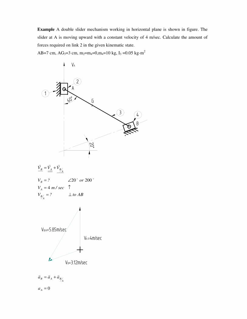
Example A double slider mechanism working in horizontal plane is shown in figure. The
slider at A is moving upward with a constant velocity of 4 m/sec. Calculate the amount of
forces required on link 2 in the given kinematic state.
AB=7 cm, AG3=3 cm, m2=m4=0,m4=10 kg, I3 =0.05 kg-m2
60°
20°
B
A1
2
3 4
G3
VA
ABAB VVVvvv
+=
ABto?V
sec/mV
or?V
AB
A
B
⊥=
↑=
∠=
4
20020 oo
VA=4m/sec
VB=3.12m/sec
VB/A=5.85m/sec
ABAB aaavvv
+=
0=Aa
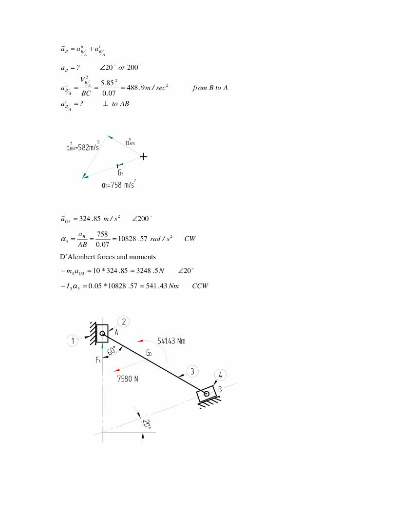
t
AB
n
ABB aaa +=
v
ABto?a
AtoBfromsec/m..
.
BC
Va
or?a
t
AB
AB
n
AB
B
⊥=
===
∠=
22
2
9488070
855
20020 oo
aB/AaB/A=582m/s
aB=758 m/s
nt
G32
2
ov20085324 2
3 ∠= s/m.aG
CWs/rad..AB
aB 2
3 5710828070
758===α
D’Alembert forces and moments
o2053248853241033 ∠==− N..*am G
CCWNm..*.I 43541571082805033 ==− α
60°
20°
B
A1
2
3 4
G3
7580 N
541.43 Nm
FA
60°
20°
B
A
2
3 4
G3
3248.5 N
541.43 Nm
FA
NA
NB
x
y+
d2
d1
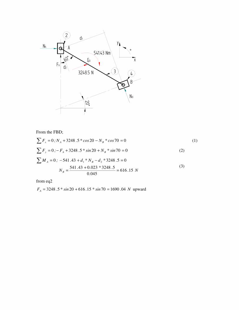
From the FBD;
∑ =−+= 07020532480 cos*Ncos*.N;F BAx (1)
∑ =++−= 07020532480 sin*Nsin*.F;F BAy (2)
N..
.*..N
.*dN*d.;M
B
BA
156160450
53248023043541
053248435410 21
=+
=
=−+−=∑ (3)
from eq2
N.sin*.sin*.FA 04169070156162053248 =+= upward
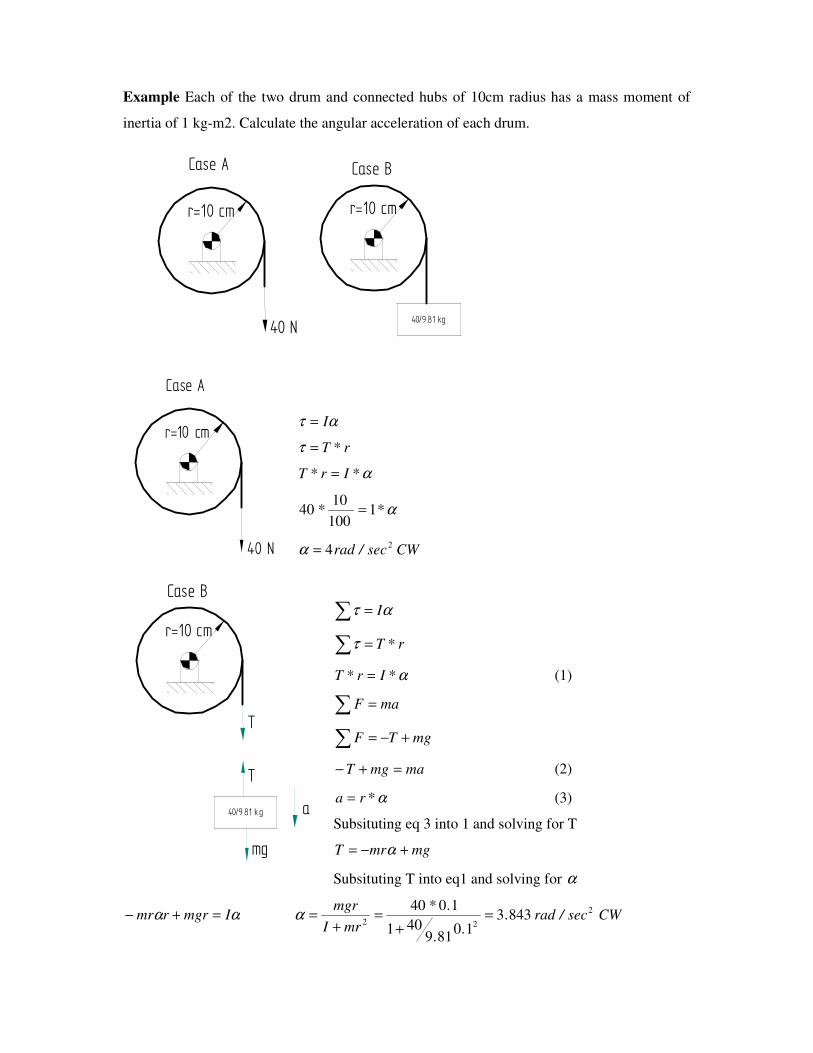
Example Each of the two drum and connected hubs of 10cm radius has a mass moment of
inertia of 1 kg-m2. Calculate the angular acceleration of each drum.
r=10 cm
40 N
r=10 cm
40/9.81 kg
Case A Case B
ατ I=
r*T=τ
α*Ir*T =
α** 1100
1040 =
CWsec/rad24=α
ατ I=∑
r*T=∑τ
α*Ir*T = (1)
maF =∑
mgTF +−=∑
mamgT =+− (2)
α*ra = (3)
Subsituting eq 3 into 1 and solving for T
mgmrT +−= α
Subsituting T into eq1 and solving for α
αα Imgrrmr =+− CWsec/rad..
.
.*
mrI
mgr 2
228433
10819
401
1040=
+=
+=α
r=10 cm
40 N
Case A
r=10 cm
40/9.81 kg
Case B
a
T
mg
T
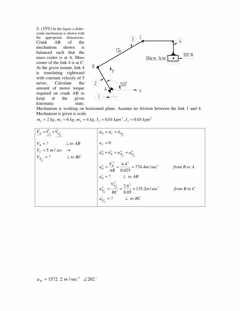
2- (35%) In the figure a slider-
crank mechanism is shown with
the appropriate dimensions. Crank AB of the
mechanism shown is
balanced such that the
mass center is at A. Mass
center of the link 4 is at C.
At the given instant, link 4
is translating rightward
with constant velocity of 5
m/sec. Calculate the
amount of motor torque
required on crank AB to
keep at the given
kinematic state.
Mechanism is working on horizontal plane. Assume no friction between the link 1 and 4.
Mechanism is given is scale. 2
3
2
2432 03.0,01.0,4,6,2 kgmIkgmIkgmkgmkgm =====
CBCB VVVvvv
+=
BCto?V
sec/mV
ABto?V
CB
C
B
⊥=
→=
⊥=
5
CBCB aaavvv
+=
0=Ca
n
CB
n
CB
t
B
n
B aaaa +=+vv
BCtoa
CtoBfrommBC
Va
ABtoa
AtoBfrommAB
Va
t
CB
CB
n
CB
t
B
Bn
B
⊥=
===
⊥=
===
?
sec/2.13505.0
6.2
?
sec/4.774025.0
4.4
22
2
222
o262sec/2.1572 2 ∠= ma B
A
D(6cm, 3cm)
B
C
1
2
3 4
100 N
120o
x
y
CG3
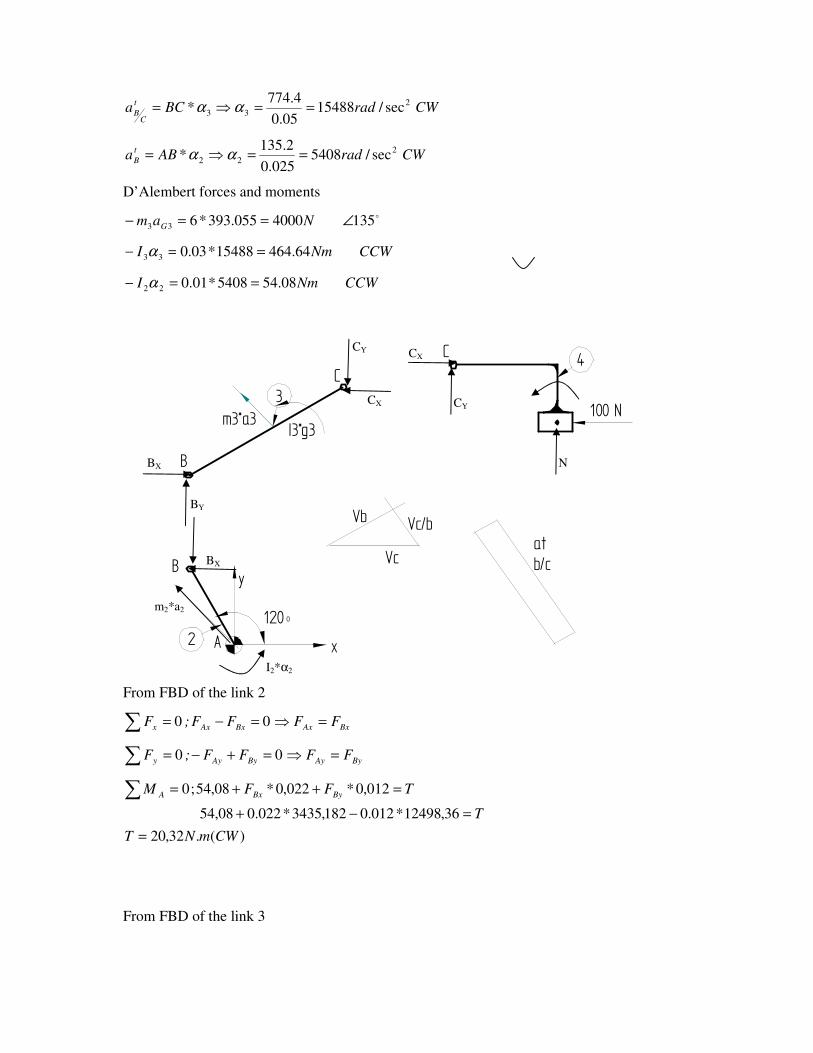
CWradBCat
CB
2
33 sec/1548805.0
4.774* ==⇒= αα
CWradABat
B
2
22 sec/5408025.0
2.135* ==⇒= αα
D’Alembert forces and moments
o1354000055.393*633 ∠==− Nam G
CCWNmI 64.46415488*03.033 ==− α
CCWNmI 08.545408*01.022 ==− α
A
atb/cB
C
2
3
4
100 N
120 o
x
y
B
C
Vc
Vb Vc/b
m3*a3I3*g3
From FBD of the link 2
∑ =⇒=−= BxAxBxAxx FFFF;F 00
∑ =⇒=+−= ByAyByAyy FFFF;F 00
)(.32,20
36,12498*012.0182,3435*022.008,54
012,0*022,0*08,54;0
CWmNT
T
TFFM ByBxA
=
=−+
=++=∑
From FBD of the link 3
m2*a2
CY
CY
BY
CX
BX
BX
CX
I2*α2
N
NF
FF
FFF
Bx
BxCx
BxCxx
182,3435
018,3335
045cos*66,4716;0
=
=+−
=−−=∑
NF
F
FFF
By
By
ByCyy
36,12498
018,333518,9163
045cos*66,4716;0
−=
=++
=++=∑
NF
amIFFM
Cy
gCxCyB
18,9163
0025,0***025,0*044,0*;0 3333
=
=+−+=∑ α
From FBD of the link 4
NFF Cxx∑ == 100;0
NF
NFF
Cy
Cyy
=
=−=∑ 0;0
∑ =++= 0017,0*03,0*;0 4 CxCyAA FFTM
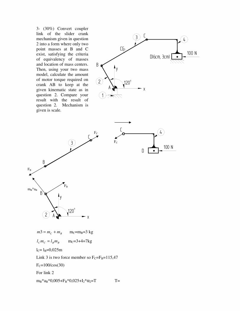
3- (30%) Convert coupler
link of the slider crank
mechanism given in question
2 into a form where only two
point masses at B and C
exist, satisfying the criteria
of equivalency of masses
and location of mass centers.
Then, using your two mass
model, calculate the amount
of motor torque required on
crank AB to keep at the
given kinematic state as in
question 2. Compare your
result with the result of
question 2. Mechanism is
given is scale.
A
D
B
C
2
3
4
100 N
120o
x
y
B
C
BC mmm +=3 mC=mB=3 kg
BBCC mlml = mC=3+4=7kg
lC= lB=0,025m
Link 3 is two force member so FC=FB=115,47
FC=100/cos(30)
For link 2
mB*aB*0,005+FB*0,025+I2*α2=T T=
A
D(6cm, 3cm)
B
C
1
2
3 4
100 N
120o
x
y
CG3
mB*aB
FB
FB
FC
FC
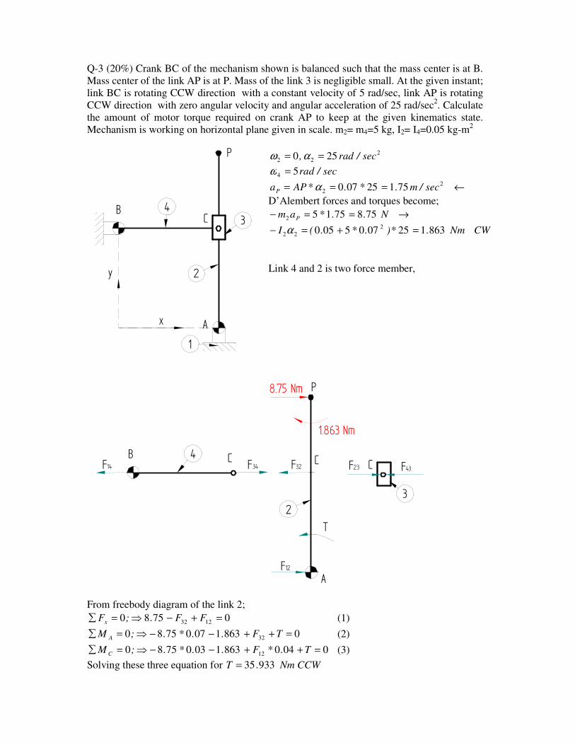
Q-3 (20%) Crank BC of the mechanism shown is balanced such that the mass center is at B.
Mass center of the link AP is at P. Mass of the link 3 is negligible small. At the given instant;
link BC is rotating CCW direction with a constant velocity of 5 rad/sec, link AP is rotating
CCW direction with zero angular velocity and angular acceleration of 25 rad/sec2. Calculate
the amount of motor torque required on crank AP to keep at the given kinematics state.
Mechanism is working on horizontal plane given in scale. m2= m4=5 kg, I2= I4=0.05 kg-m2
2
22 250 sec/rad, == αω
sec/rad54 =ω
←=== 2
2 75125070 sec/m.*.*APaP α
D’Alembert forces and torques become;
→==− N..*am P 75875152
CWNm.*).*.(I 8631250705050 2
22 =+=− α
Link 4 and 2 is two force member,
A
BC
23
4
P
CC
T
1.863 Nm
8.75 Nm
F32 F23 F43F34F14
F12
From freebody diagram of the link 2;
07580 1232 =+−⇒=∑ FF.;Fx (1)
086310707580 32 =++−−⇒=∑ TF..*.;M A (2)
004086310307580 12 =++−−⇒=∑ T.*F..*.;M C (3)
Solving these three equation for CCWNm.T 93335=
A
BC
1
2
3
x
y
4
P