Embed Size (px)
Citation preview

IEEE TRANSACTIONS ON ANTENNAS AND PROPAGATION, VOL. 51, NO. 7, JULY 2003 1649
Resonant Frequency of Circular Microstrip AntennaCovered With Dielectric Superstrate
Debatosh Guha and Jawad Y. Siddiqui
Abstract—A simple design formulation to compute accurate resonantfrequencies of circular microstrip antennas covered with dielectric super-strates is proposed in this paper. It alleviates the rigorous mathematicalanalyzes and large computational time of some earlier works. This theoryis widely applicable to both high and low dielectric constant superstrates asverified with the experiments and other theoretical models. Of all theories,the present one shows the closest approximation with the measurementsrevealing average percent error as low as 0.52%. The extension of this for-mulation to predict the accurate design data for conventional microstripcircular antennas are also verified with different experiments and avail-able improved theories for various sets of antenna parameters.
Index Terms—Microstrip antenna.
I. INTRODUCTION
Microstrip patch covered with dielectric superstrates finds someadded interests in recent years [1]–[4]. The superstrate protectsthe antenna from environmental hazards and its effects on antennacharacteristics are being investigated for more than a decade [5]–[18].Particularly, the geometry of a circular microstrip patch coveredwith a dielectric superstrate has recently been analyzed by Losadaet al. [3] employing Galerkin’s method in the Hankel Transformdomain. A variant of this formulation has been reported by Bouttout[4] using method of moment solution and scalar Hankel transformwas used by Luk [7]. The radiation properties of dielectric loadedplanar and spherical circular microstrip antennas were also studiedby Bhattacharyya [11] and Wong [12], respectively. The increasinguse and development of this structure needs accurate prediction of theresonant frequency to design the antenna, since it suffers from narrowbandwidth whereas both the dielectric constant and the thickness ofthe superstrate affect its resonant frequency significantly [3], [6]. Thisin turn requires a simple CAD formula of the resonant parameter asthe previous calculations are based on rigorous mathematical stepsand manipulations.
In this paper, we propose a simple formula to calculate accurate res-onant frequency of circular microstrip patch antenna covered with adielectric superstrate, shown in Fig. 1. This is based on an improvedcavity model [19] and Bernhard’s work [17] to determine the effectivedielectric constant of the substrate in multilayered media. Comparedto the electromagnetic simulator or the formulations reported in [3],[4], the present one is more advantageous from the considerations ofcomputational time and mathematical steps involved. The computedresults are compared with other theoretical data. Some new measure-ments along with those reported in [3] are also compared with ourmodel for different substrate-superstrate combinations. The validity ofthis model in predicting the values for conventional antennas are alsoverified.
Manuscript received November 13, 2001; revised May 8, 2002. This workwas suported by the Center of Advanced Study in Radio Physics and Electronics,University of Calcutta, and the Society for Applied Microwave Electronics En-gineering and Research, Calcutta Center.
The authors are with the Institute of Radio Physics and Electronics, Uni-versity of Calcutta, Calcutta 700009, India (e-mail: [email protected]; [email protected]).
Digital Object Identifier 10.1109/TAP.2003.813620
Fig. 1. Coax-fed microstrip circular patch antenna covered with a dielectricsuperstrate: a cross-sectional view.
II. THEORY
The resonant frequency of a circular microstrip patch covered witha dielectric superstrate as shown in Fig. 1 can be expressed followingthe formula for conventional geometry as [19]
fr;nm =�nmc
2�ae�p"r;e�
(1)
where�nm is the mth zero of the derivative of the Bessel function oforder n,c is the velocity of light in free space,"r;e� is the effective rela-tive permittivity of the medium below the patch andae� is the effectiveradius of the circular patch in presence of a dielectric superstrate.
One or more dielectric layers above a microstrip patch causes thechange in the fringing fields between the patch and the ground planeand that effect is accounted for by the effective relative permittivity"r;e� . The general formulations obtained for a rectangular patch withlengthl and widthw [17] can be extended to calculate"r;e� for a cir-cular patch sandwiched between two dielectric layers (Fig. 1) and thusit can be more explicitly written as [17]
"r;e� = "r1p1 + "r1(1� p1)2
� "r22p2p3 + "r2 p2p4 + (p3 + p4)
2
� "r22p2p3p4+"r1("r2p3+p4)(1�p1�p4)
2
+"r2p4 p2p4 + (p3 + p4)2 �1
(2)
where,
p1 =1� h1
2we
ln�
h1we � 1 � p4 (3)
p2 =1� p1 � p3 � 2p4 (4)
p3 =h1 � g
2we
ln�we
h1
cos �g
2h
� 0:5 + h
h+ 0:5g�
h
+sin0:5g�
h1(5)
p4 =h1
2we
� ln �
2� h1
2we
(6)
g =2h1�
� arctan�h
h
�
2
w
h� 2
(7)
we ="0r
"r;e�w+0:882h1+0:164h1
("0r�1)
("0r)2
+h1("0r�1)
�"0rln 0:94+
w
2h1+1:451 (8)
0018-926X/03$17.00 © 2003 IEEE
1650 IEEE TRANSACTIONS ON ANTENNAS AND PROPAGATION, VOL. 51, NO. 7, JULY 2003
"0r =2"r;e� � 1 + 1 + 10h
w
�
1 + 1 + 10h
w
�
(9)
w = a(� � 2): (10)
The quantitieswe and "0r are determined by an iteration techniquestarting with an approximation"0r = "r1 and"r;e� = "0r [17, sec-tion IIB].
Equation (10) is derived from an equivalence relation between a rect-angular patch (resonating length= l, width= w) and a circular patch(radius= a) resonating at the same frequency, that is,l � 2a [20].Equal circumference was considered as the basis of equivalence, likeequal surface areas in [21], to account for equal static fringing fields.
The radius of a magnetic wall cavity under a microstrip disk is ex-tended by the fringing electric fields and is expressed asae� [22]. Thefringing fields are very much dependent on the relative characteris-tics of the substrate and superstrate, as indicated by Alexopoulos andJackson [5]. They showed that a superstrate with dielectric constanthigher than that of the substrate, at a proper thickness may reduce thesurface wave excitation to a great extent. In tune to this result, a newequivalent dielectric constant of the medium-1 is modeled to calculateae� as
"re ="r1"r;e�
(11)
The variation of"r;e� and hence"re with the relative properties of thesubstrate and superstrate can also be surmised from Fig. 2 andae� canbe expressed as [19]
ae� = a (1 + q) (12)
whereq can be evaluated from [19, (9)–(14)] with"re expressed as(11).
III. RESULTS
The effective relative permittivity determined as (2) is examined fordifferent substrate-superstrate combinations as a function of the thick-ness of the superstrate in Fig. 2. The effect of the thickness of the super-strate is almost insignificant when"r2 � "r1, but that for"r2 � "r1,results in significant change in"r;e� values. The values of"r;e� com-puted for"r2 = 1were also compared with that reported in [19, eq.(3)]for differenta=h1 values and very close correspondence between thosetwo were observed.
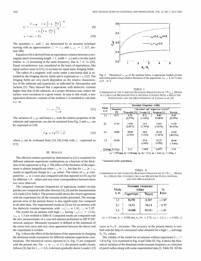
The computed resonant frequencies of superstrate loaded circularpatches are compared with other theories [3], [4] and the measurementsof Losada [3] in Table I. The present model shows the closest agreementwith the experiment for all the resonant modes presented. The averagepercent error of the present theory is also significantly low comparedto all other data. The experimental results in [3] are for an antenna withlow dielectric constant superstrate, with"r2="r1 = 1:05, "r1 = 2:43.
The results for an antenna with high"r2 having"r2="r1 = 2:545,"r1 = 2:2 are verified in Table II. Computed results are compared withthe new measurements of a coax-fed antenna performed on HP 8720Cnetwork analyzer. Measured resonance is defined as the minimum ofthe return loss curve and very close agreement between the theory andthe experiment is evident.
Fig. 3 shows the effect of the thickness of the superstrate in changingthe dominant mode resonances for different substrate-superstrate com-binations. The theoretical curves reported in [3, Fig. 7] are comparedwith the present one. For"r2 = "r1 = 2:5, the present model closelyfollows [3], but for"r2 = 9:8, it deviates gradually above Losada’s [3]
Fig. 2. Theoretical" of the medium below a superstrate loaded circularmicrostrip patch versus relative thickness of the superstrate.h = 1:5875mm,a=h = 5.
TABLE ICOMPARISON OF THECOMPUTEDRESONANTFREQUENCIES OFTM MODES
IN A CIRCULAR MICROSTRIPPATCH ANTENNA COVEREDWITH A DIELECTRIC
SUPERSTRATE AND THEMEASUREMENTS OFLOSADA et al. [3]
TABLE IICOMPARISON OF THECOMPUTEDRESONANTFREQUENCIES OFTM MODES
IN A DIELECTRIC COVERED CIRCULAR MICROSTRIPPATCH ANTENNA
AND OUR MEASUREMENTS
(a = 5.9 mm,h = 0.508 mm,h =h = 2.76,� = 2.2,� = 2.545� )
curve ash2=h1 increases. The accuracy of the present theory is veri-fied with the help of a measured value obtained for a high"r2 and largeh2=h1 values.
The validity of the model for an antenna without superstrate ("r2 =1:0 in Fig. 1) is examined in Fig. 4 and Table III. Fig. 4 shows the theo-retical variation of the dominant mode resonant frequency as a functionof patch radius along with some experimental data [3, Table II]. All the

IEEE TRANSACTIONS ON ANTENNAS AND PROPAGATION, VOL. 51, NO. 7, JULY 2003 1651
Fig. 3. Dominant mode resonant frequency of a superstrate loaded circularpatch antenna versush =h . Computed, [3]: h = 1:5875 mm,a=h = 5, " = 2:5; � � � Computed, Experiment:h = 0:508 mm,a=h = 11:6, " = 2:2, " = 5:6.
Fig. 4. Dominant mode resonant frequency of a circular patch antenna withoutsuperstrate versusa=h . " = 2:43, " = 1:0, h = 0:49 mm.
TABLE IIICOMPARISON OF THECOMPUTEDRESONANTFREQUENCIES OFTM MODES
IN A CIRCULAR MICROSTRIPPATCH ANTENNA WITHOUT SUPERSTRATE AND
THE MEASUREMENTS OFLOSADA et al. [3]
measurements are found to fall on the theoretical curve. Table III com-pares the measured data [3] for first few modes with the present theoryalong with two more recent models. This theory can predict the closeapproximations forTM11, TM01, andTM12 modes while those for2,1 and 3,1 modes are better due to [19].
IV. CONCLUSION
The Microstrip antenna with a dielectric cover has become popularfor mobile communication equipment. The theories available for cir-cular patch loaded with a superstrate are based on rigorous mathemat-ical analyses and huge computational steps. In this paper, a simple aswell as accurate formulation of the resonant frequency of such struc-ture is proposed which should be highly suitable to a design engineer.The theory is widely applicable to both high and low dielectric constantsuperstrates as verified with different experimental results. Moreover,experiments show the closest agreement with the present theory whilecompared with others also. The present model can also be extended topredict accurate values for the conventional antennas also.
ACKNOWLEDGMENT
The authors would like to thank Dr. P. K. Saha, Dr. A. N. Chakravarti,and Dr. P. K. Basu, University of Calcutta, for their encouragement andinspiration.
REFERENCES
[1] R. B. Waterhouse, D. M. Kokotoff, and C. R. Birtcher, “Highly efficientmultilayered printed antenna suitable for MMIC’s and OEICs,”Microw.Opt. Tech. Lett., vol. 20, no. 3, pp. 155–156, Feb. 1999.
[2] Z. F. Liu, P. S. Kooi, L. W. Li, M. S. Leong, and T. S. Yeo, “Method fordesigning broad-band microstrip antennas in multilayered planar struc-tures,”IEEE Trans. Antennas Propagat., vol. 47, pp. 1416–1420, Sept.1999.
[3] V. Losada, R. R. Boix, and M. Horno, “Resonant modes of circularmicrostrip patches in multilayered substrates,”IEEE Trans MicrowaveTheory Tech., vol. 47, pp. 488–497, Apr. 1999.
[4] F. Bouttout, F. Benabdelaziz, and A. Khellaf, “Closed-form hankel trans-forms for circular disk basis modes involving Chebyshev polynomialsand edge condition,”Electron. Lett., vol. 36, no. 10, pp. 866–867, May2000.
[5] N. G. Alexopoulos and D. R. Jackson, “Fundamental superstrate (cover)effects on printed circuit antennas,”IEEE Trans. Antennas Propagat.,vol. 32, pp. 807–816, Aug. 1984.
[6] A. K. Bhattacharyya and T. Tralman, “Effects of dielectric superstrateon patch antennas,”Electron. Lett., vol. 24, pp. 356–358, 1988.
[7] K. M. Luk, W. Y. Tam, and C. L. Yip, “Analysis of circular microstripantennas with superstrate,”Proc. Inst. Elect. Eng., pt. H, vol. 136, pp.261–262, Mar. 1989.
[8] D. R. Jackson, “The RCS of a rectangular microstrip patch in a sub-strate-superstrate geometry,”IEEE Trans. Antennas Propagat., vol. 38,pp. 1–8, Jan. 1990.
[9] A. Benalla and K. C. Gupta, “Multiport network model for rectangularmicrostrip patches covered with a dielectric layer,”Proc. Inst. Elect.Eng., vol. 137, pp. 377–383, 1990.
[10] Y. Tu and D. C. Chang, “Effect of a cover layer on the edge admittanceof a wide microstrip,”IEEE Trans. Antennas Propagat., vol. 39, pp.354–358, 1991.
[11] A. K. Bhattacharyya, “Characteristics of circular patch on thick sub-strate and superstrate,”IEEE Trans. Antennas Propagat., vol. 39, pp.1038–1041, 1991.
[12] K. L. Wong, S.-F.Sun-Fu Hsiao, and H.-T.Hong-Twu Chen, “Resonanceand radiation of a superstrate-loaded spherical-circular microstrip patchantenna,”IEEE Trans. Antennas Propagat., vol. 41, pp. 686–690, May1993.
[13] J. S. Row and K. L. Wong, “Resonance in a superstrate-loaded rectan-gular microstrip structure,”IEEE Trans. Microwave Theory Tech., vol.MTT-41, pp. 1349–1355, Aug. 1993.
[14] W. S. Chen, K. L. Wong, and J. S. Row, “Superstrate loading effectson the circular polarization and cross-polarization characteristics of arectangular microstrip patch antenna,”IEEE Trans. Antennas Propagat.,vol. 42, pp. 260–264, Feb. 1994.
[15] R. Shavit, “Dielectric cover effect on rectangular microstrip antennaarray,” IEEE Trans. Antennas Propagat., vol. 42, pp. 1180–1184, Aug.1994.
[16] S.-S. Zhong, G. Liu, and G. Qasim, “Closed form expressions for reso-nant frequency of rectangular patch antenna with multidielectric layers,”IEEE Trans. Antennas Propagat., vol. 42, pp. 1360–1363, Sept. 1994.

1652 IEEE TRANSACTIONS ON ANTENNAS AND PROPAGATION, VOL. 51, NO. 7, JULY 2003
[17] J. T. Bernhard and C. J. Tousignant, “Resonant frequencies of rectan-gular microstrip antennas with flush and spaced dielectric superstrates,”IEEE Trans. Antennas Propagat., vol. 47, pp. 302–308, Feb. 1999.
[18] V. Losada, R. R. Boix, and M. Horno, “Full-wave analysis of circular mi-crostrip resonators in multilayered media containing uniaxial anisotropicdielectrics, magnetized ferrites, and chiral materials,”IEEE Trans Mi-crowave Theory Tech., vol. 48, pp. 1057–1064, June 2000.
[19] D. Guha, “Resonant frequency of circular microstrip antennas with andwithout air gaps,”IEEE Trans. Antennas Propagat., vol. 49, pp. 55–59,Jan. 2001.
[20] Handbook of Microstrip Antennas, J. R. James and P. S. Hall, Eds., PeterPeregrinus, London, U.K., 1989.
[21] Y. Suzuki and T. Chiba, “Computer analysis method for arbitrary shapedmicrostrip antenna with multi terminals,”IEEE Trans. Antennas Prop-agat., vol. 32, pp. 585–590, June 1984.
[22] I. Wolff and M. Knoppik, “Rectangular and circular microstrip diskcapacitors and resonators,”IEEE Trans Microwave Theory Tech., vol.MTT-22, pp. 857–864, Oct. 1974.
Gain Enhancement of a Circularly PolarizedEquilateral-Triangular Microstrip Antenna
With a Slotted Ground Plane
Jieh-Sen Kuo and Gui-Bin Hsieh
Abstract—A novel circular polarization (CP) design of a single-feedequilateral-triangular microstrip antenna with enhanced antenna gain ispresented. This CP design is obtained by placing three triangular slotsat properly locations below the equilateral-triangular radiating patch inthe ground plane. By adjusting one of the triangular slot’s side lengthsslightly longer than that of the others, two orthogonal near-degenerateresonant modes for CP radiation can be excited. Measured antenna gainin this study can easily be increased by 3.3 dBi (5.1 dBi versus 1.8 dBi),as compared to the same height, substrate material, operating frequencyand radiating patch shape of a regular equilateral-triangular microstripantenna without triangular slots in the ground plane. Prototype antennais fabricated for experimental evaluation. Simulated and measured resultsare presented.
Index Terms—Gain enhancement, microstrip antenna, slotted groundplane.
I. INTRODUCTION
Microstrip antennas are widely used in a broad range of military andcommercial applications mainly because of their advantageous featuresin terms of low profile, low cost, lightweight, and easy manufactura-bility. However, two major disadvantages associated with microstripantennas are low gain and narrow bandwidth. Most works have beendone in improving the bandwidth, but little in enhancing the antennagain. On the whole, previous studies have reported that a 4.6–6.5%[1]–[3] impedance bandwidth is achievable with one-layer patch an-tennas using a thin FR4 dielectric substrate with thickness 1.6 mm andrelative permittivity 4.4. Some gain enhanced antennas have also beenstudied, but most require increasing antenna’s height, such as with par-asitic patch [4], [5], with dielectric resonator [6], [7], with photonicbandgap (PBG) structures [8], [9], and so on. The CP operation hasthe distinct advantage of being insensitive to the orientation between
Manuscript received November 13, 2001; revised May 8, 2002.The authors are with the Department of Electrical Engineering, Chinese Mil-
itary Academy, Fengshan Kaohsiung, Taiwan 830, R.O.C.Digital Object Identifier 10.1109/TAP.2003.813621
the transmitter and receiver, and is therefore wildly used in wirelesscommunication systems, so this paper is concerned mainly with gainenhancement of microstrip antenna for CP radiation.
In this paper, we proposed a new design concept of equilateral-trian-gular microstrip antenna with a triangular slotted ground plane, whichis simple and different from that reported in [4]–[9]. It is found that, byproperly embedding three triangular slots below the radiating patch inthe finite ground plane of a microstrip antenna, an enhanced antennagain for the proposed design is observed. From the IE3D simulationresults, the radiation efficiency of the proposed antenna with FR4 sub-strate is 54%, which is much greater than that (28%) of the referenceantenna with the same patch and substrate parameters as the proposedantenna. The increase in the radiation efficiency is probably associatedto the embedded tringular slots in the ground plane, which lowers thequality factor and shortens the excited patch surface current paths ofthe proposed antenna, and may account for the observed antenna gainenhancement for the proposed antenna. These characteristics suggestthat the embedded triangular slots in the ground plane are more effec-tive than the techniques reported in [4]–[9].
In this study, the case a single-feed equilateral-triangular microstripantenna (antenna A) with a truncated tip for CP radiation is first demon-strated and experimentally studied. To demonstrate other possible ap-plications of the CP radiation design, the case with a triangular slotembedded in the ground plane of a single-feed equilateral-triangularmicrostrip antenna (antenna B) for CP radiation is also presented. Theabove two cases are compared with the proposed antenna for achievinggain enhancement of the equilateral-triangular microstrip antenna (an-tenna C) for CP radiation.
II. A NTENNA CONFIGURATIONS
Fig. 1(a) and (b) shows the geometry of antenna A and B. Fig. 2shows the geometry of proposed gain-enhanced microstrip antenna.They are printed on a microwave substrate of thicknessh and relativepermittivity "r . The size of the ground plane is chosen to be square andhas dimensionsG � G. Equilateral-triangular radiating patch of sidelengthL is also chosen.
In Fig. 1(a), a small triangular tip of equal side length of�d1 istruncated in the triangular patch [10], [11]. In Fig. (1b), a triangularslot having equal side length of�d2 is embedded in the square groundplane. It is expected that, due to the truncated-tip and embedded-slotperturbation, the effective excited patch surface current path in they
direction is slightly shorter than that in thex-direction which givesthey-direction resonant mode a resonant frequency slightly larger thanthat of thex-direction resonant mode. That is. The fundamental modeTM10 can be split into two orthogonal near-degenerate modes for CPradiation. By selecting the probe feed at pointP [10], [11], left-handCP operation can be obtained. Right-hand CP operation is obtained byfeeding the patch at pointPm (the mirror image of pointP with respectto the patch’s center line).
The proposed CP design for a gain-enhanced microstrip antenna isshown in Fig. 2. This CP design is obtained by placing three triangularslots at properly locations below the three corners of equilateral-triangular radiating patch in the ground plane. By adjusting the toptriangular slot’s side length(�d3) slightly longer than the bottomtriangular slots’ side length(�d), two orthogonal near-degenerateresonant modes for CP radiation can be generated. By placing a50- probe feed atP , left-hand CP operation can be obtained.Right-hand CP operation is also obtained by feeding the patch atpoint Pm.
0018-926X/03$17.00 © 2003 IEEE
![Numerical Computation of Resonant Frequency of …In [11,12], circular microstrip patch antenna with dual frequency operation is designed by shorting the patch and the results are](https://img.pdfslide.us/doc/110x75/5fb6ae89d8a49b714e202e92/numerical-computation-of-resonant-frequency-of-in-1112-circular-microstrip-patch.jpg)
![BRIEF PAPER Size Miniaturized Rat-Race Coupler Using Open ... · ral compact microstrip resonant cell (C-SCMRC) resonator is demonstrated in [3]. Recently, metamaterial based sub-wavelength](https://img.pdfslide.us/doc/110x75/5d038e5c88c99322638b5ff8/brief-paper-size-miniaturized-rat-race-coupler-using-open-ral-compact-microstrip.jpg)


![A RECONFIGURABLE U-KOCH MICROSTRIP ANTENNA FOR … · geometries, and that Koch fractal antennas are multiband structures. The authors of [10] related multiple resonant frequencies](https://img.pdfslide.us/doc/110x75/5e764ec1b5799e0f2317c4ff/a-reconfigurable-u-koch-microstrip-antenna-for-geometries-and-that-koch-fractal.jpg)