Embed Size (px)
Citation preview

Article
Calculation of resonant frequency for a microstrip antenna with vertical slots using Applying Adaptive network-based fuzzy inference system Mahmood Abbasi Layegh 1,*, Changiz Ghobadi 2 and Javad Nourinia 3
1 No. 13,5th floor, Aria Apartment, Asadi Street, Molavi 2 Avenue, Urmia, West Azarbaijan Province, Iran; [email protected]
2 Urmia University, Faculty of Electrical Engineering; [email protected] 3 Urmia University, Faculty of Electrical Engineering; [email protected] * Correspondence: [email protected]; Tel.: +98-914-141-5082
Abstract— This paper attempts at applying adaptive network-based fuzzy inference system (ANFIS) for analysis of the resonant frequency of a microstrip rectangular patch antenna with two equal size slots which are placed on the patch vertically. The resonant frequency is calculated as the position of slots is shifted to the right and left sides on the patch. As a result , the antenna resonates at more than one frequency . Commonly, machine algorithms based on artificial neural networks are employed to recognize the whole resonant frequencies. However ,they fail to estimate the resonant frequencies correctly as in some cases variations are not very sensible and the resonant frequencies overlap each other . It can be concluded that artificial neural networks could be replaced in such designs by the adaptive network-based fuzzy Inference system due to its high approximation capability and much faster convergence rate.
Keywords: microstrip antenna, vertical slots , adaptive network-based fuzzy Inference system , resonant frequency, artificial neural networks .
1.Introduction
Microstrip antennas have gained lots of attention among telecommunication engineers and researchers especially in recent years because they have very simple installation. Furthermore ,they have a lot of advantages as being cheap ,light in terms of weight and easy to work with. As well as the abovementioned ,when they have slotted structures in various forms, they can enhance the bandwidth to such a degree that multi bands can be covered simultaneously .In addition ,radiation loss in these antennas has been reported to be much lower [1–5]. Obviously ,it is much preferable to take advantage of only one single multiband antenna instead of several antennas which is able to operate in different frequency bands .Reportedly ,when a slot is cut appropriately on the microstrip patch with the right dimensions ,a multiband slot antenna can be fabricated more efficiently. [1, 6] Hereupon , it is attempted to evaluate the effect of changing the position and the width of horizontal slots on the antenna characteristics
Preprints (www.preprints.org) | NOT PEER-REVIEWED | Posted: 2 October 2017 doi:10.20944/preprints201710.0008.v1
© 2017 by the author(s). Distributed under a Creative Commons CC BY license.
Peer-reviewed version available at Technologies 2017, 5, 75; doi:10.3390/technologies5040075
especially the parameter of resonant frequency. Here ,the feed line of the antenna is fixed in order to make the analysis of the antenna much simpler . In previous works ANNs have successfully been introduced to compute different parameters of the rectangular antennas [7-10 ]. In [11], the frequency in which microstrip antennas in rectangular form resonates is computed by using connectionist systems namely artificial neural networks.
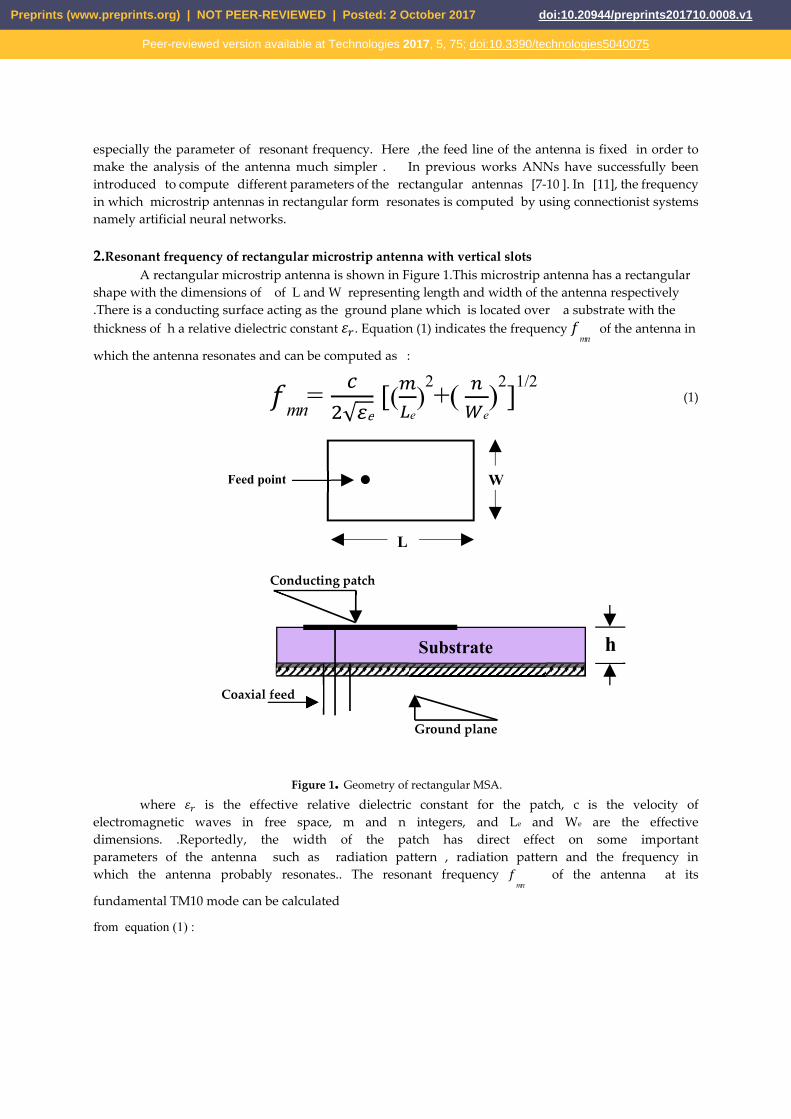
2.Resonant frequency of rectangular microstrip antenna with vertical slots
A rectangular microstrip antenna is shown in Figure 1.This microstrip antenna has a rectangular shape with the dimensions of of L and W representing length and width of the antenna respectively .There is a conducting surface acting as the ground plane which is located over a substrate with the thickness of h a relative dielectric constant . Equation (1) indicates the frequency
mn of the antenna in
which the antenna resonates and can be computed as :
mn= √ e [( e)
2+(e)2]1/2
(1)
where is the effective relative dielectric constant for the patch, c is the velocity of electromagnetic waves in free space, m and n integers, and Le and We are the effective dimensions. .Reportedly, the width of the patch has direct effect on some important parameters of the antenna such as radiation pattern , radiation pattern and the frequency in which the antenna probably resonates.. The resonant frequency
mn of the antenna at its
fundamental TM10 mode can be calculated
from equation (1) :
Feed point W
L
Conducting patch
h Substrate
Ground plane
Coaxial feed
Figure 1. Geometry of rectangular MSA.
Preprints (www.preprints.org) | NOT PEER-REVIEWED | Posted: 2 October 2017 doi:10.20944/preprints201710.0008.v1
Peer-reviewed version available at Technologies 2017, 5, 75; doi:10.3390/technologies5040075

10= e√ e
Le can be defined as follows:
Le= L + 2Δ L
is referred to as the effective relative dielectric constant and Le is the effective length showing the field fringing at the end of the patch .They are indicating the effects of the non-uniform medium and the fringing fields at each end of the patch . Two formulas below in equations (2) and (3) presented by Schneider (1969) and Hammerstad (1975) can be used to calculate
(W) and L.
e(W)= r + r ( ⁄ ) (2)
L= 0.412h
[ e( ) . ][ e( ) . ] [( / ) . ][( / ) . ] (3)
Figure 2 illustrates inset feed microstrip antenna with two horizontal slots. The antenna is
fabricated . On FR-4 substrate , with a thickness of 1.6 mm and dielectric constant of = 4.2. Table 1 gives the values of the proposed microstrip antenna .
Figure 2. Full ground plane microstrip antenna without slots and with vertical slots fabricated on FR-4 with a thickness of 1.6 mm
Table 1. The values of the proposed microstrip antenna with its parameters without slots
Parameter mm Parameter mm L1= L feed 3 LG 15.528
L4 9 WG 18.44 L5 5 W4 1L6 5 W1 3.2
Preprints (www.preprints.org) | NOT PEER-REVIEWED | Posted: 2 October 2017 doi:10.20944/preprints201710.0008.v1
Peer-reviewed version available at Technologies 2017, 5, 75; doi:10.3390/technologies5040075

L7 15.2 - - The first thing to do is to calculate the optimum feeding line .As can be seen from Figure 3 ,the best feed line is calculated when L1=3mm.
Figure 3. Optimizing the feed line for the proposed antenna
After optimizing the feed line ,the length and width of the radiating patch must be examined .Here
L5 and L6 are considered to be equal .It means they have the same value but as the value of L5 is changed ,the value of L6 is varied as well to obtain the optimum length and width of the patch. Figure 4 shows S11 curves in dB versus frequency to evaluate and obtain the best results for the length and width of the proposed patch antenna.
0 2 4 6 8 10 12 14 16 18 20Frequency (GHz)
-30
-25
-20
-15
-10
-5
0
L1=3mmL1=4mmL1=5mmL1=6mm
Preprints (www.preprints.org) | NOT PEER-REVIEWED | Posted: 2 October 2017 doi:10.20944/preprints201710.0008.v1
Peer-reviewed version available at Technologies 2017, 5, 75; doi:10.3390/technologies5040075

Figure 4. S11 curves for calculation of the best dimensions of the proposed patch antenna
As explained before ,the two slots are placed in a vertical form on the patch .In the case of vertical slots ,they are exactly placed in the middle point of L5 and L6 .Then they are shifted from the beginning point of L5 or L6 to the endpoint of the patch in order to find the best point and optimized location .The results reveal that as the slots get closer to the right and left sides of the patch (the endpoints), a better response can be expected. Figure 5 shows the values of Xslot when -2mm≤ Xslot ≤ 2mm from which the best position is selected as Xslot=1mm s i.e. a distance of 1 mm from the right and left sides of the patch.
Preprints (www.preprints.org) | NOT PEER-REVIEWED | Posted: 2 October 2017 doi:10.20944/preprints201710.0008.v1
Peer-reviewed version available at Technologies 2017, 5, 75; doi:10.3390/technologies5040075
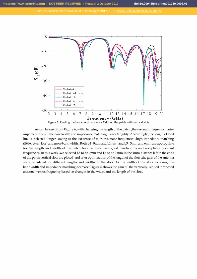
Figure 5. Finding the best coordination for Xslot on the patch with vertical slots
As can be seen from Figure 6 ,with changing the length of the patch ,the resonant frequency varies imperceptibly but the bandwidth and impedance matching vary tangibly .Accordingly ,the length of feed line is selected longer owing to the existence of more resonant frequencies ,high impedance matching (little return loss) and more bandwidth.. Both L4 =9mm and 10mm , and L5= 5mm and 6mm are appropriate for the length and width of the patch because they have good bandwidths and acceptable resonant frequencies. In this work ,we selected L5 to be 4mm and L4 to be 9 mm.In the 1mm distance left to the ends of the patch vertical slots are placed and after optimization of the length of the slots ,the gain of the antenna were calculated for different lengths and widths of the slots. As the width of the slots increases, the bandwidth and impedance matching decrease. Figure 6 shows the gain of the vertically- slotted proposed antenna versus frequency based on changes in the width and the length of the slots.
Preprints (www.preprints.org) | NOT PEER-REVIEWED | Posted: 2 October 2017 doi:10.20944/preprints201710.0008.v1
Peer-reviewed version available at Technologies 2017, 5, 75; doi:10.3390/technologies5040075
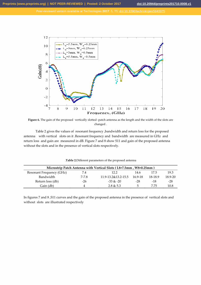
Figure 6. The gain of the proposed vertically slotted -patch antenna as the length and the width of the slots are changed .
Table 2 gives the values of resonant frequency ,bandwidth and return loss for the proposed antenna with vertical slots on it .Resonant frequency and bandwidth are measured in GHz and return loss and gain are measured in dB. Figure 7 and 8 show S11 and gain of the proposed antenna without the slots and in the presence of vertical slots respectively.
.Table 2.Different parameters of the proposed antenna
Microstrip Patch Antenna with Vertical Slots ( L8=7.5mm , W8=0.25mm ) Resonant Frequency (GHz) 7.4 12.2 14.6 17.5 19.3
Bandwidth 7-7.8 11.9-13.2&13.2-15.5 16.9-18 18-18.9 18.9-20 Return loss (db) -26 -33 & -20 -28 -18 -28
Gain (db) 4 2.8 & 5.3 5 7.75 10.8
In figures 7 and 8 ,S11 curves and the gain of the proposed antenna in the presence of vertical slots and without slots are illustrated respectively
Preprints (www.preprints.org) | NOT PEER-REVIEWED | Posted: 2 October 2017 doi:10.20944/preprints201710.0008.v1
Peer-reviewed version available at Technologies 2017, 5, 75; doi:10.3390/technologies5040075

Figure 7. S11 parameters for the patch antenna without and with vertical slots
Figure 8. The gain of the patch antenna without and with vertical slots
Preprints (www.preprints.org) | NOT PEER-REVIEWED | Posted: 2 October 2017 doi:10.20944/preprints201710.0008.v1
Peer-reviewed version available at Technologies 2017, 5, 75; doi:10.3390/technologies5040075

Figure 9 shows the radiation patterns of the proposed microstrip patch antenna with v slots at resonant frequencies of 7.3GHz ,12.5GHz ,17.4GHz and 19.2 GHz for E- and H-plane including both co-polarization and cross-polarization. It can be seen that the radiation patterns are nearly omnidirectional in most of the frequencies mentioned above.
Figure 9. Radiation patterns of the proposed vertically-slotted microstrip antenna
3.Adaptive neuro-fuzzy inference system (ANFIS) Basically a fuzzy inference system is composed of five functional blocks (see Figure10). The main
contribution of this system can be attributed to computation of some data both in granular and imprecise form. Here, membership functions are employed to compute numerically small and big datasets. Fuzzy inference system (FIS) originates form the principles pertaining to fuzzy sets , fuzzy if-then rules and fuzzy reasoning. Fuzzy inference system can be strongly used to classify data if necessary . Whenever , the inputs and outputs of a fuzzy system are determined by variables ,the following steps ought to be done successively . The first step which is called fuzzification which indicates expressing variables in the form of fuzzy and then calculating their dependence in the fuzzy set. As the membership function can take numerous shapes ,the ones in a smooth shape can be more efficient. After that ,the level of statement is appraised and some algebraic operators are used to approximate classification task .Activation is the next step in order to calculate the activations of the rules applied in the system .Finally all the output activations are connected to each other and this step is called accumulation.[12-13]
Preprints (www.preprints.org) | NOT PEER-REVIEWED | Posted: 2 October 2017 doi:10.20944/preprints201710.0008.v1
Peer-reviewed version available at Technologies 2017, 5, 75; doi:10.3390/technologies5040075

Figure 10. A fuzzy inference system
4. How to take advantage of the ANFIS in calculating the resonant frequency of rectangular antennas operating at multi bands
Figure 11.below illustrates S11 curves for the whole possible situations Since the antenna resonates in more than one frequency ,it is necessary that an appropriate algorithm to detect the resonant frequencies be selected .Experimentally ,artificial neural networks are unable to diagnose the frequencies . As ,in many cases the resonant frequencies are very similar or close to each other .
Figure 11. S11 obtained from the whole possible cases simulated by HFSS
Hence, , the ANFIS was utilized in order to analyze multiple resonant frequencies of the proposed rectangular patch antenna having vertical slots on it . For the ANFIS, the inputs are the width of the vertical slots and also the position of slots and the output is the measured resonant frequency .The network was trained by 82 samples and the training was performed in 220 epochs. The ANFIS is able to do simulation and analyses of existing relationship between the input and output data through a hybrid learning.The next step is to identify optimal parameters of the presumed FIS. Commonly ,measurement and simulation are considered as two ways of generating data which can be used in antennas. . Here , the data were obtained through simulation results using HFSS because it is practically impossible to design and fabricate the whole antennas mentioned earlier.
decision- making unit
fuzzification interface
Knowledge base
data base rule base defuzzification
interface
(fuzzy) (fuzzy)
(crisp) (crisp)
output input
Preprints (www.preprints.org) | NOT PEER-REVIEWED | Posted: 2 October 2017 doi:10.20944/preprints201710.0008.v1
Peer-reviewed version available at Technologies 2017, 5, 75; doi:10.3390/technologies5040075
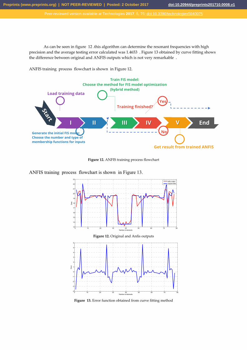
As can be seen in figure 12 .this algorithm can determine the resonant frequencies with high precision and the average testing error calculated was 1.4653 . Figure 13 obtained by curve fitting shows the difference between original and ANFIS outputs which is not very remarkable . ANFIS training process flowchart is shown in Figure 12.
Figure 12. ANFIS training process flowchart
ANFIS training process flowchart is shown in Figure 13.
Figure 12. Original and Anfis outputs
Figure 13. Error function obtained from curve fitting method
0 10 20 30 40 50 60 70 8013
14
15
16
17
18
19
20
21
22
23
Number of elements
Dat
a
anfis outputoriginal data
0 10 20 30 40 50 60 70 80-4
-3
-2
-1
0
1
2
3
4
5
6
Number of elements
Erro
r
Generate the initial FIS mode: Choose the number and type of membership functions for inputs
I II III IV V End
Get result from trained ANFIS
Training finished?
Yes
No
Train FIS model:Choose the method for FIS model optimization
(hybrid method) Load training data
Preprints (www.preprints.org) | NOT PEER-REVIEWED | Posted: 2 October 2017 doi:10.20944/preprints201710.0008.v1
Peer-reviewed version available at Technologies 2017, 5, 75; doi:10.3390/technologies5040075

5.Conclusion Microstrip patch antennas are versatile structures which can be modified by adding simple slots
both vertically or horizontally in the design structure to overcome selected limitations of conventional patch antennas. The antenna can provide improved bandwidth enhancement, under certain conditions, while maintaining many of the desirable features of conventional patches. However, it is difficult to determine or predict resonant frequencies and bandwidths especially when the changes in terms of position of slots and the widths of slots are relatively small. The paper concludes that results obtained using Adaptive-network-based fuzzy inference system(ANFIS)technique are quite satisfactory and far outweigh some algorithms such as ANN , SVM and RVM as they will not be able to distinguish the variations easily . Reference
1. Microstrip Antenna Design Handbook, Artech House, Norwood, MA, 2001. R. Garg, P. Bhartia, I. Bahl, A. Ittipiboon.
2. Wong, K. L. “Compact and Broadband Microstrip Antennas”. NewYork: J. Wiley and Sons, 2002. 3. W.-S. Chen, A novel broadband design of a printed rectangular slot antenna for wireless applications.
Microw. J. 49(1), 122 (2006). 4. W.-S. Chen, A novel broadband design of a printed rectangular slot antenna for wireless applications.
Microw. J. 49(1), 122 (2006) 5. Zhang, L., Y. C. Jiao, G. Zhao, Y. Song, X. M. Wang, and F.-S. Zhang, “A novel CPW-FED monopole
antenna for multiband operation," Journal of Electromagnetic Waves and Applications, Vol. 22, No. 5-6, 741-747, 2008.
6. J.-Y. Sze and K.-L. Wong, “Bandwidth enhancement of a microstripline-fedprinted wide-slot antenna,” IEEE Trans. Antennas Propag., vol. 49, no.
7. Guney. K.; Sagiroglu. S.; Erler. M.: Design of rectangular microstrip antennas with the use of artificial
neural networks, Neural Network World 4 (2002). 361-370.
8. Gultekin. S. S.; Guney. K.: Sagiroglu. S.: Neural networks for the calculation of bandwidth of rectangular microstrip antennas. Applied computational Electromagnetics Society (ACES) Journal 18 (2003). 46-56.
9. Karaboga, D.: Guney, K,: Sagiroglu. S.; Erler, M.: Neural computation of resonant frequency of electrically
thin and thick rectangular microstrip antennas. lEE Proc. Microw. Antennas Propagat. 146 (1999), 155-159.
10. Guney, K.; Erler, M,; Sagiroglu, S.: Artificial neural networks for the resonant resistance calculation of electrically thin and thick rectangular microstrip antennas, Electromagnetics 20(2000), 387-400.
11. Guney. K.: Sagiroglu, S.: Erler. M.: Comparison of neural networks for resonant frequency computation of electrically thin and thick rectangular microstrip antennas. J. of Electromagnetic Waves and Applications 15 (2001), 1121—1145
12. .J.S.R. Jang, ‘‘Anfis: Adaptive-network-based fuzzy inference system’’, IEEE Trans. Syst.,Man, Cyber., 23, pp. 665–685, 1993.
13. Jang, J.S.R.; Sun, C.T.; Mizutani, E.: Neuro-fuzzy and soft computing: A computational approach to learning and machine intelligence. Prentice-Hall: Upper Saddle River, NJ,1997.
Preprints (www.preprints.org) | NOT PEER-REVIEWED | Posted: 2 October 2017 doi:10.20944/preprints201710.0008.v1
Peer-reviewed version available at Technologies 2017, 5, 75; doi:10.3390/technologies5040075
![A RECONFIGURABLE U-KOCH MICROSTRIP ANTENNA FOR … · geometries, and that Koch fractal antennas are multiband structures. The authors of [10] related multiple resonant frequencies](https://img.pdfslide.us/doc/110x75/5e764ec1b5799e0f2317c4ff/a-reconfigurable-u-koch-microstrip-antenna-for-geometries-and-that-koch-fractal.jpg)