Embed Size (px)
Citation preview
Contents
Introduction IP Fragmentation and ReassemblyIssues with IP FragmentationAvoid IP Fragmentation: What TCP MSS Does and How It WorksScenario 1Scenario 2What Is PMTUD?Scenario 3Scenario 4Problems with PMTUDCommon Network Topologies that Need PMTUDWhat Is a Tunnel?Considerations Regarding Tunnel InterfacesThe Router as a PMTUD Participant at the Endpoint of a TunnelScenario 5Scenario 6"Pure" IPsec Tunnel ModeScenario 7Scenario 8GRE and IPsec TogetherScenario 9Scenario 10More RecommendationsRelated Information
Introduction
The document describes how IP Fragmentation and Path Maximum Transmission Unit Discovery(PMTUD) work and also discusses some scenarios that involve the behavior of PMTUD whencombined with different combinations of IP tunnels. The current widespread use of IP tunnels inthe Internet has brought the problems that involve IP Fragmentation and PMTUD to the forefront.
IP Fragmentation and Reassembly
The IP protocol was designed for use on a wide variety of transmission links. Although themaximum length of an IP datagram is 65535, most transmission links enforce a smaller maximumpacket length limit, called an MTU. The value of the MTU depends on the type of the transmissionlink. The design of IP accommodates MTU differences since it allows routers to fragment IPdatagrams as necessary. The receiving station is responsible for the reassembly of the fragmentsback into the original full size IP datagram.
IP fragmentation involves breaking a datagram into a number of pieces that can be reassembledlater. The IP source, destination, identification, total length, and fragment offset fields, along with
the "more fragments" and "don't fragment" flags in the IP header, are used for IP fragmentationand reassembly. For more information about the mechanics of IP fragmentation and reassembly,see RFC 791 .
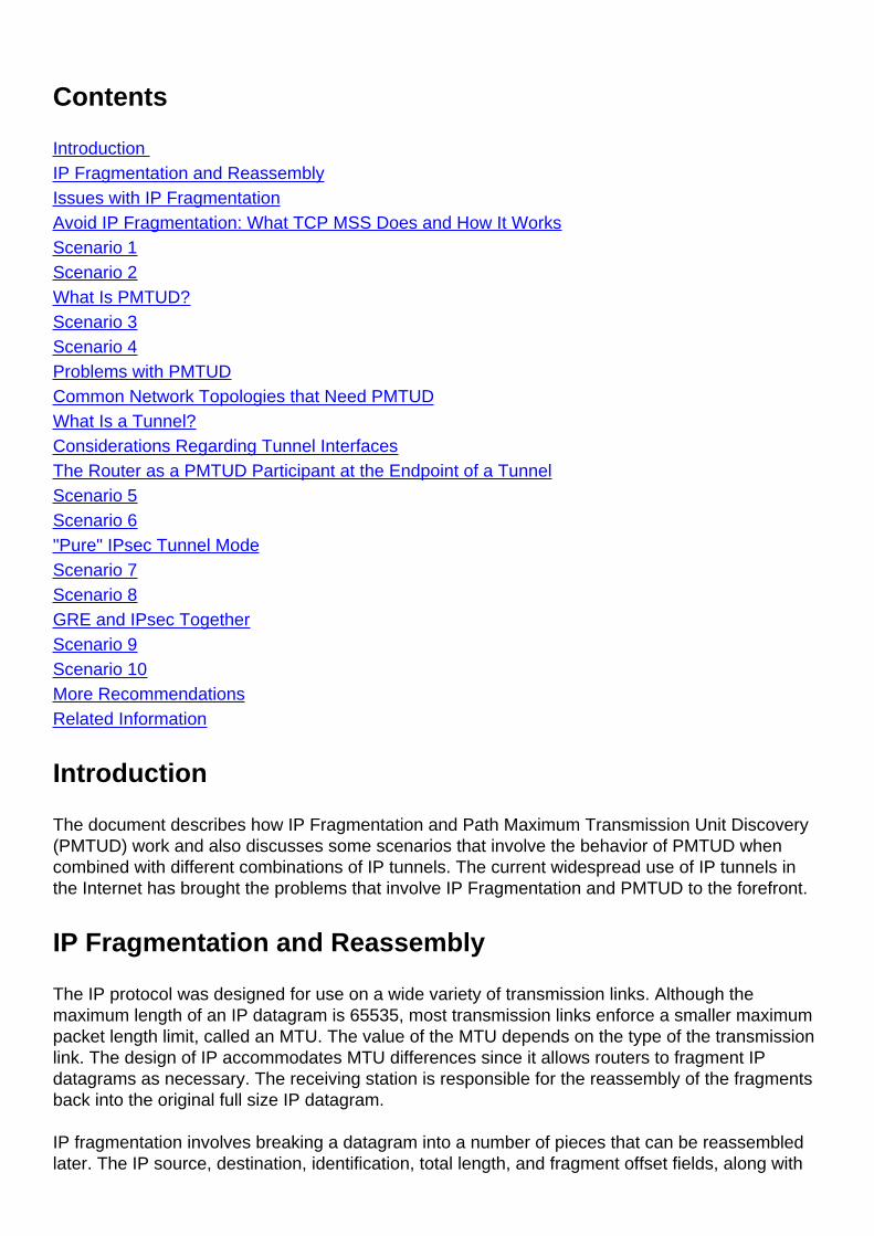
This image depicts the layout of an IP header.
The identification is 16 bits and is a value assigned by the sender of an IP datagram to aid in thereassembly of the fragments of a datagram.
The fragment offset is 13 bits and indicates where a fragment belongs in the original IP datagram.This value is a multiple of eight bytes.
In the flags field of the IP header, there are three bits for control flags. It is important to note thatthe "don't fragment" (DF) bit plays a central role in PMTUD because it determines whether or not apacket is allowed to be fragmented.
Bit 0 is reserved, and is always set to 0. Bit 1 is the DF bit (0 = "may fragment," 1 = "do notfragment"). Bit 2 is the MF bit (0 = "last fragment," 1 = "more fragments").
Value Bit 0 Reserved Bit 1 DF Bit 2 MF0 0 May Last1 0 Do not More
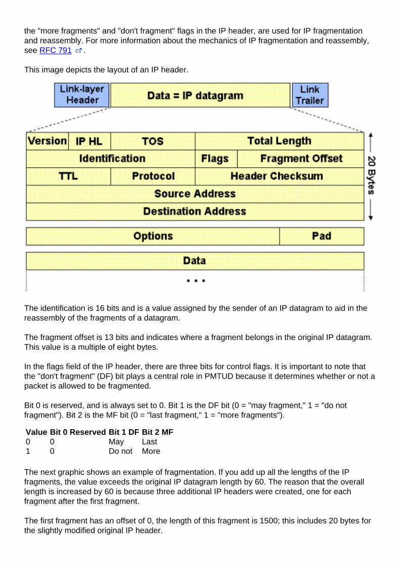
The next graphic shows an example of fragmentation. If you add up all the lengths of the IPfragments, the value exceeds the original IP datagram length by 60. The reason that the overalllength is increased by 60 is because three additional IP headers were created, one for eachfragment after the first fragment.
The first fragment has an offset of 0, the length of this fragment is 1500; this includes 20 bytes forthe slightly modified original IP header.
The second fragment has an offset of 185 (185 x 8 = 1480), which means that the data portion ofthis fragment starts 1480 bytes into the original IP datagram. The length of this fragment is 1500;this includes the additional IP header created for this fragment.
The third fragment has an offset of 370 (370 x 8 = 2960), which means that the data portion of thisfragment starts 2960 bytes into the original IP datagram. The length of this fragment is 1500; thisincludes the additional IP header created for this fragment.
The fourth fragment has an offset of 555 (555 x 8 = 4440), which means that the data portion ofthis fragment starts 4440 bytes into the original IP datagram. The length of this fragment is 700bytes; this includes the additional IP header created for this fragment.
It is only when the last fragment is received that the size of the original IP datagram can bedetermined.
The fragment offset in the last fragment (555) gives a data offset of 4440 bytes into the original IPdatagram. If you then add the data bytes from the last fragment (680 = 700 - 20), that gives you5120 bytes, which is the data portion of the original IP datagram. Then, adding 20 bytes for an IPheader equals the size of the original IP datagram (4440 + 680 + 20 = 5140).
Issues with IP Fragmentation
There are several issues that make IP fragmentation undesirable. There is a small increase inCPU and memory overhead to fragment an IP datagram. This holds true for the sender as well asfor a router in the path between a sender and a receiver. Creating fragments simply involvescreating fragment headers and copying the original datagram into the fragments. This can be donefairly efficiently because all the information needed to create the fragments is immediatelyavailable.
Fragmentation causes more overhead for the receiver when reassembling the fragments becausethe receiver must allocate memory for the arriving fragments and coalesce them back into onedatagram after all of the fragments are received. Reassembly on a host is not considered a
problem because the host has the time and memory resources to devote to this task.
But, reassembly is very inefficient on a router whose primary job is to forward packets as quicklyas possible. A router is not designed to hold on to packets for any length of time. Also a router thatdoes reassembly chooses the largest buffer available (18K) with which to work because it has noway to know the size of the original IP packet until the last fragment is received.
Another fragmentation issue involves how dropped fragments are handled. If one fragment of anIP datagram is dropped, then the entire original IP datagram must be resent, and it will also befragmented. You see an example of this with Network File System (NFS). NFS, by default, has aread and write block size of 8192, so a NFS IP/UDP datagram will be approximately 8500 bytes(which includes NFS, UDP, and IP headers). A sending station connected to an Ethernet (MTU1500) will have to fragment the 8500 byte datagram into six pieces; five 1500 byte fragments andone 1100 byte fragment. If any of the six fragments are dropped because of a congested link, thecomplete original datagram will have to be retransmitted, which means that six more fragments willhave to be created. If this link drops one in six packets, then the odds are low that any NFS datacan be transferred over this link, since at least one IP fragment would be dropped from each NFS8500 byte original IP datagram.
Firewalls that filter or manipulate packets based on Layer 4 (L4) through Layer 7 (L7) informationin the packet might have trouble processing IP fragments correctly. If the IP fragments are out oforder, a firewall might block the non-initial fragments because they do not carry the informationthat would match the packet filter. This would mean that the original IP datagram could not bereassembled by the receiving host. If the firewall is configured to allow non-initial fragments withinsufficient information to properly match the filter, then a non-initial fragment attack through thefirewall could occur. Also, some network devices (such as Content Switch Engines) direct packetsbased on L4 through L7 information, and if a packet spans multiple fragments, then the devicemight have trouble enforcing its policies.
Avoid IP Fragmentation: What TCP MSS Does and How It Works
The TCP Maximum Segment Size (MSS) defines the maximum amount of data that a host iswilling to accept in a single TCP/IP datagram. This TCP/IP datagram might be fragmented at theIP layer. The MSS value is sent as a TCP header option only in TCP SYN segments. Each side ofa TCP connection reports its MSS value to the other side. Contrary to popular belief, the MSSvalue is not negotiated between hosts. The sending host is required to limit the size of data in asingle TCP segment to a value less than or equal to the MSS reported by the receiving host.
Originally, MSS meant how big a buffer (greater than or equal to 65496K) was allocated on areceiving station to be able to store the TCP data contained within a single IP datagram. MSS wasthe maximum segment (chunk) of data that the TCP receiver was willing to accept. This TCPsegment could be as large as 64K (the maximum IP datagram size) and it could be fragmented atthe IP layer in order to be transmitted across the network to the receiving host. The receiving hostwould reassemble the IP datagram before it handed the complete TCP segment to the TCP layer.
Below are a couple of scenarios that show how MSS values are set and used to limit TCPsegment sizes, and therefore, IP datagram sizes.
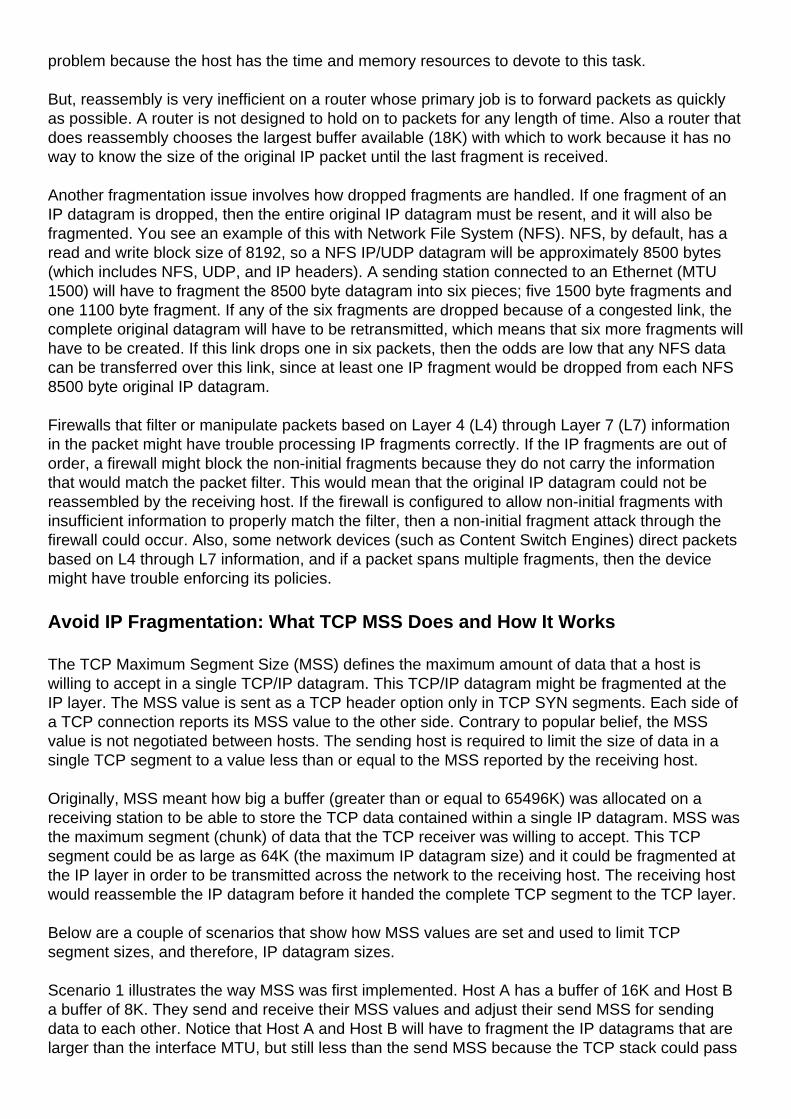
Scenario 1 illustrates the way MSS was first implemented. Host A has a buffer of 16K and Host Ba buffer of 8K. They send and receive their MSS values and adjust their send MSS for sendingdata to each other. Notice that Host A and Host B will have to fragment the IP datagrams that arelarger than the interface MTU, but still less than the send MSS because the TCP stack could pass
16K or 8K bytes of data down the stack to IP. In Host B's case, packets could be fragmentedtwice, once to get onto the Token Ring LAN and again to get onto the Ethernet LAN.
Scenario 1
Host A sends its MSS value of 16K to Host B.1.Host B receives the 16K MSS value from Host A.2.Host B sets its send MSS value to 16K.3.Host B sends its MSS value of 8K to Host A.4.Host A receives the 8K MSS value from Host B.5.Host A sets its send MSS value to 8K.6.
In order to assist in avoiding IP fragmentation at the endpoints of the TCP connection, theselection of the MSS value was changed to the minimum buffer size and the MTU of the outgoinginterface (- 40). MSS numbers are 40 bytes smaller than MTU numbers because MSS is just theTCP data size, which does not include the 20 byte IP header and the 20 byte TCP header. MSS isbased on default header sizes; the sender stack must subtract the appropriate values for the IPheader and the TCP header dependent on what TCP or IP options are used.
The way MSS now works is that each host will first compare its outgoing interface MTU with itsown buffer and choose the lowest value as the MSS to send. The hosts will then compare theMSS size received against their own interface MTU and again choose the lower of the two values.
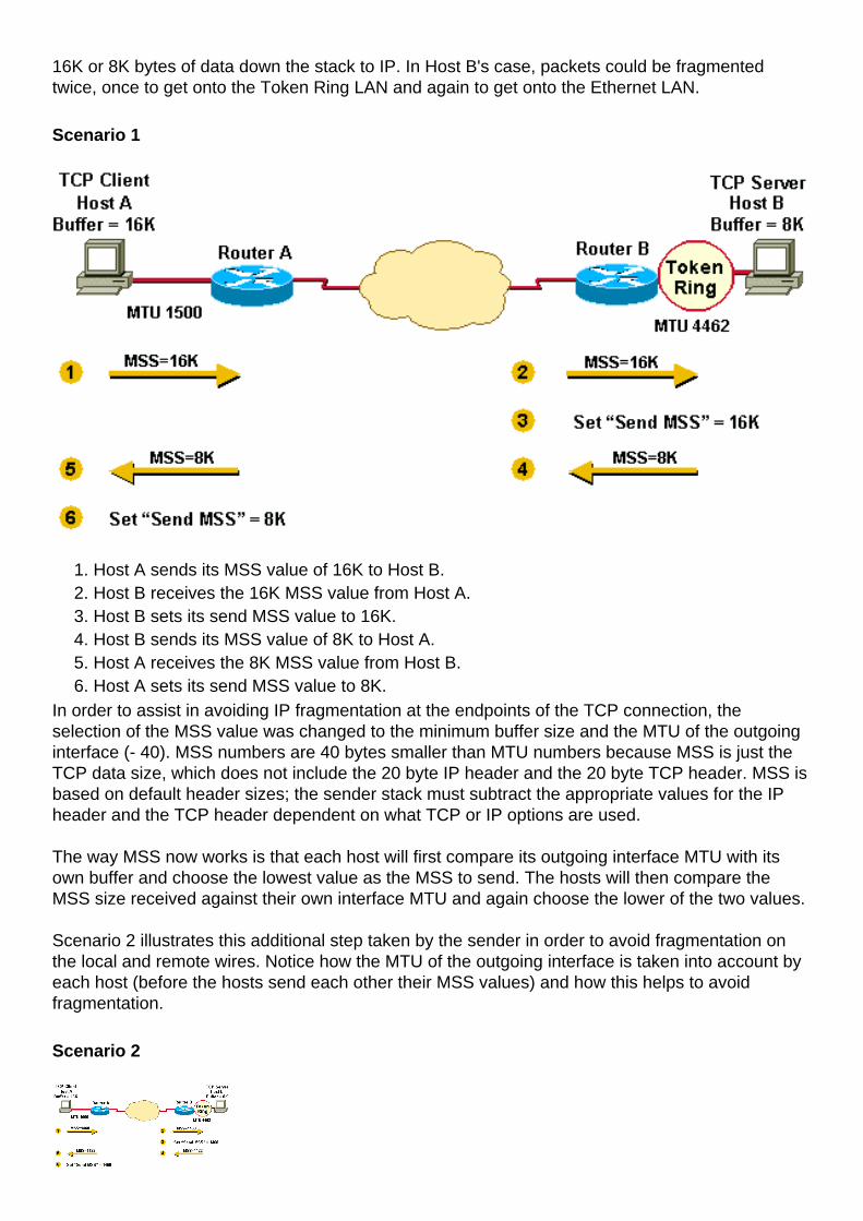
Scenario 2 illustrates this additional step taken by the sender in order to avoid fragmentation onthe local and remote wires. Notice how the MTU of the outgoing interface is taken into account byeach host (before the hosts send each other their MSS values) and how this helps to avoidfragmentation.
Scenario 2
Host A compares its MSS buffer (16K) and its MTU (1500 - 40 = 1460) and uses the lowervalue as the MSS (1460) to send to Host B.
1.
Host B receives Host A's send MSS (1460) and compares it to the value of its outboundinterface MTU - 40 (4422).
2.
Host B sets the lower value (1460) as the MSS for sending IP datagrams to Host A.3.Host B compares its MSS buffer (8K) and its MTU (4462-40 = 4422) and uses 4422 as theMSS to send to Host A.
4.
Host A receives Host B's send MSS (4422) and compares it to the value of its outboundinterface MTU -40 (1460).
5.
Host A sets the lower value (1460) as the MSS for sending IP datagrams to Host B.6.1460 is the value chosen by both hosts as the send MSS for each other. Often the send MSSvalue will be the same on each end of a TCP connection.
In Scenario 2, fragmentation does not occur at the endpoints of a TCP connection because bothoutgoing interface MTUs are taken into account by the hosts. Packets can still become fragmentedin the network between Router A and Router B if they encounter a link with a lower MTU than thatof either hosts' outbound interface.
What Is PMTUD?
TCP MSS as described earlier takes care of fragmentation at the two endpoints of a TCPconnection, but it does not handle the case where there is a smaller MTU link in the middlebetween these two endpoints. PMTUD was developed in order to avoid fragmentation in the pathbetween the endpoints. It is used to dynamically determine the lowest MTU along the path from apacket's source to its destination.
Note: PMTUD is only supported by TCP and UDP. Other protocols do not support it. IfPMTUD is enabled on a host, and it almost always is, all TCP/IP or UDP packets from thehost will have the DF bit set.
When a host sends a full MSS data packet with the DF bit set, PMTUD reduces the send MSSvalue for the connection if it receives information that the packet would require fragmentation. Ahost usually "remembers" the MTU value for a destination since it creates a "host" (/32) entry in itsrouting table with this MTU value.
If a router tries to forward an IP datagram, with the DF bit set, onto a link that has a lower MTUthan the size of the packet, the router will drop the packet and return an Internet Control MessageProtocol (ICMP) "Destination Unreachable" message to the source of this IP datagram, with thecode that indicates "fragmentation needed and DF set" (type 3, code 4). When the source stationreceives the ICMP message, it will lower the send MSS, and when TCP retransmits the segment,it will use the smaller segment size.
Here is an example of an ICMP "fragmentation needed and DF set" message that you might seeon a router after the debug ip icmp command is turned on:
ICMP: dst (10.10.10.10) frag. needed and DF set
unreachable sent to 10.1.1.1
This diagram shows the format of ICMP header of a "fragmentation needed and DF set""Destination Unreachable" message.
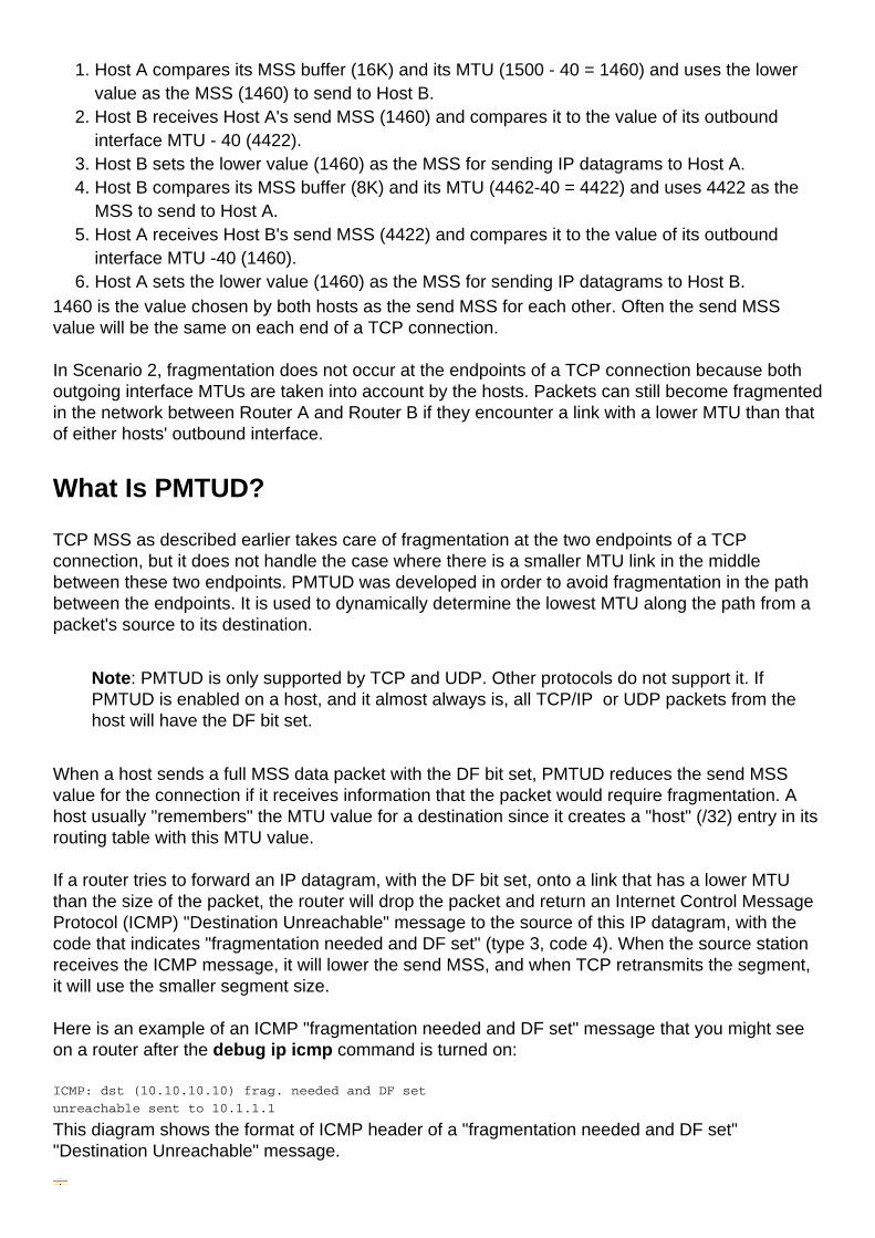
Per RFC 1191 , a router that returns an ICMP message which indicates "fragmentation neededand DF set" should include the MTU of that next-hop network in the low-order 16 bits of the ICMPadditional header field that is labeled "unused" in the ICMP specification RFC 792 .
Early implementations of RFC 1191 did not supply the next hop MTU information. Even when thisinformation was supplied, some hosts ignore it. For this case, RFC 1191 also contains a table thatlists the suggested values by which the MTU should be lowered during PMTUD. It is used by hostsin order to arrive more quickly at a reasonable value for the send MSS.
PMTUD is done continually on all packets because the path between sender and receiver canchange dynamically. Each time a sender receives a "Can't Fragment" ICMP messages it willupdate the routing information (where it stores the PMTUD).
Two possible things can happen during PMTUD:
The packet can get all the way to the receiver without being fragmented.Note: In order for arouter to protect the CPU against DoS attacks, it throttles the number of ICMP unreachablemessages that it would send, to two per second. Therefore, in this context, if you have anetwork scenario in which you expect that the router would need to respond with more thantwo ICMP messages (type = 3, code = 4) per second (can be different hosts), you would wantto disable the throttling of ICMP messages with the no ip icmp rate-limit unreachable [df]interface command.
●
The sender can get ICMP "Can't Fragment" messages from any (or every) hop along the pathto the receiver.
●
PMTUD is done independently for both directions of a TCP flow. There might be cases wherePMTUD in one direction of a flow triggers one of the end stations to lower the send MSS and theother end station keeps the original send MSS because it never sent an IP datagram large enoughto trigger PMTUD.
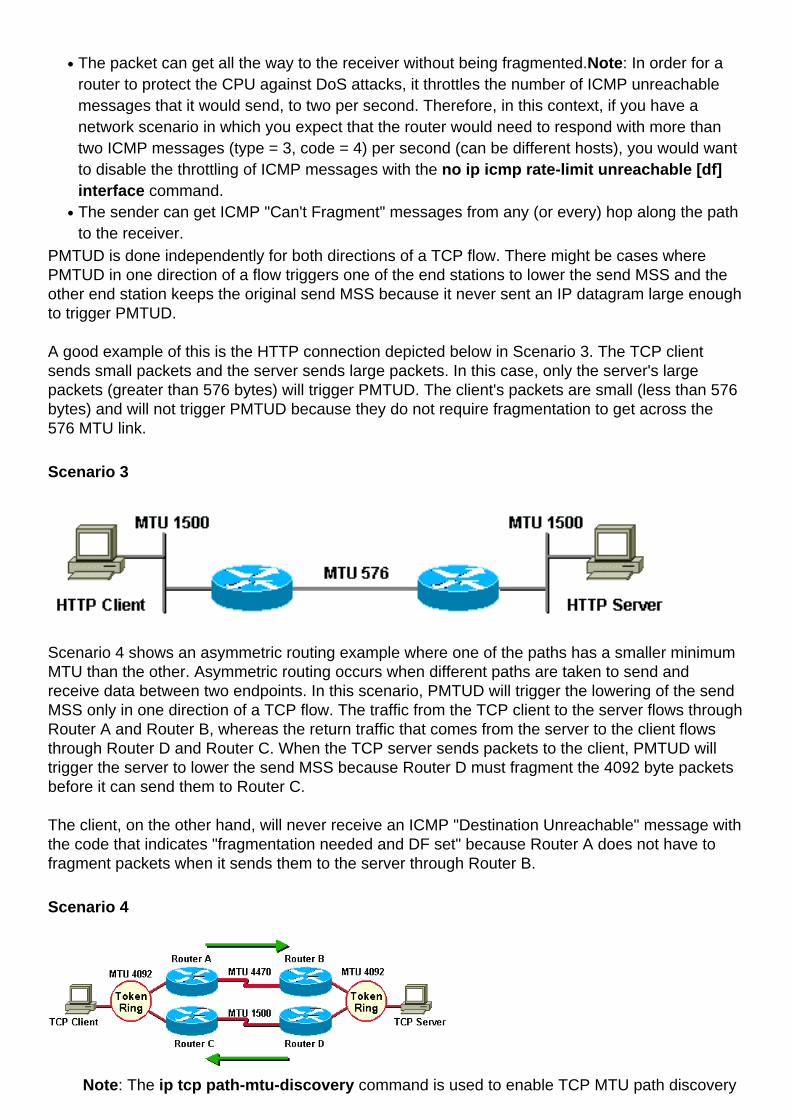
A good example of this is the HTTP connection depicted below in Scenario 3. The TCP clientsends small packets and the server sends large packets. In this case, only the server's largepackets (greater than 576 bytes) will trigger PMTUD. The client's packets are small (less than 576bytes) and will not trigger PMTUD because they do not require fragmentation to get across the576 MTU link.
Scenario 3
Scenario 4 shows an asymmetric routing example where one of the paths has a smaller minimumMTU than the other. Asymmetric routing occurs when different paths are taken to send andreceive data between two endpoints. In this scenario, PMTUD will trigger the lowering of the sendMSS only in one direction of a TCP flow. The traffic from the TCP client to the server flows throughRouter A and Router B, whereas the return traffic that comes from the server to the client flowsthrough Router D and Router C. When the TCP server sends packets to the client, PMTUD willtrigger the server to lower the send MSS because Router D must fragment the 4092 byte packetsbefore it can send them to Router C.
The client, on the other hand, will never receive an ICMP "Destination Unreachable" message withthe code that indicates "fragmentation needed and DF set" because Router A does not have tofragment packets when it sends them to the server through Router B.
Scenario 4
Note: The ip tcp path-mtu-discovery command is used to enable TCP MTU path discovery
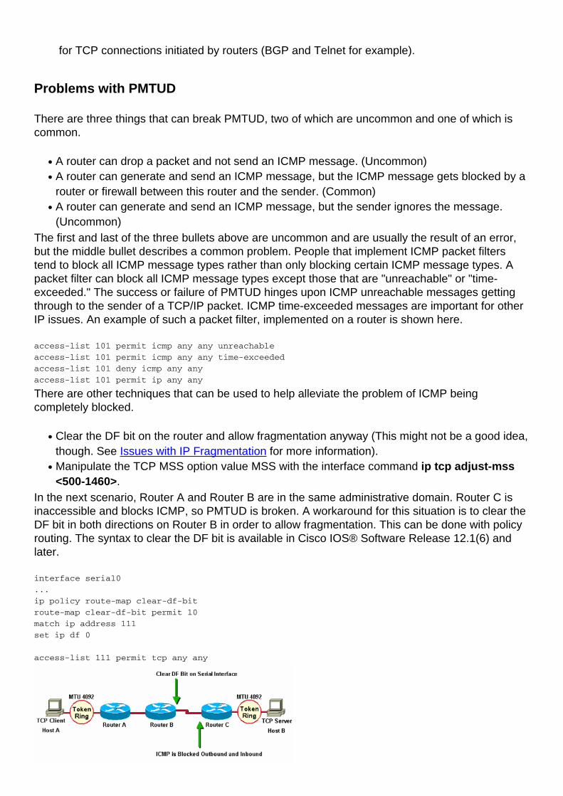
for TCP connections initiated by routers (BGP and Telnet for example).
Problems with PMTUD
There are three things that can break PMTUD, two of which are uncommon and one of which iscommon.
A router can drop a packet and not send an ICMP message. (Uncommon)●
A router can generate and send an ICMP message, but the ICMP message gets blocked by arouter or firewall between this router and the sender. (Common)
●
A router can generate and send an ICMP message, but the sender ignores the message.(Uncommon)
●
The first and last of the three bullets above are uncommon and are usually the result of an error,but the middle bullet describes a common problem. People that implement ICMP packet filterstend to block all ICMP message types rather than only blocking certain ICMP message types. Apacket filter can block all ICMP message types except those that are "unreachable" or "time-exceeded." The success or failure of PMTUD hinges upon ICMP unreachable messages gettingthrough to the sender of a TCP/IP packet. ICMP time-exceeded messages are important for otherIP issues. An example of such a packet filter, implemented on a router is shown here.
access-list 101 permit icmp any any unreachable
access-list 101 permit icmp any any time-exceeded
access-list 101 deny icmp any any
access-list 101 permit ip any any
There are other techniques that can be used to help alleviate the problem of ICMP beingcompletely blocked.
Clear the DF bit on the router and allow fragmentation anyway (This might not be a good idea,though. See Issues with IP Fragmentation for more information).
●
Manipulate the TCP MSS option value MSS with the interface command ip tcp adjust-mss<500-1460>.
●
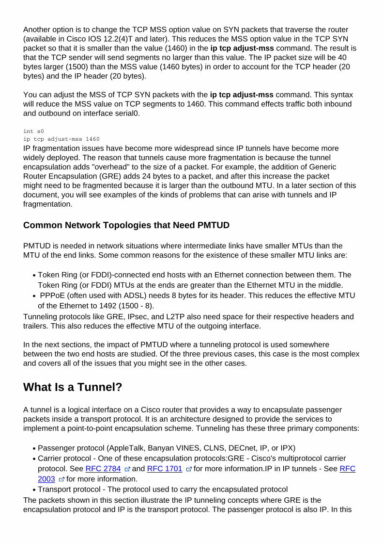
In the next scenario, Router A and Router B are in the same administrative domain. Router C isinaccessible and blocks ICMP, so PMTUD is broken. A workaround for this situation is to clear theDF bit in both directions on Router B in order to allow fragmentation. This can be done with policyrouting. The syntax to clear the DF bit is available in Cisco IOS® Software Release 12.1(6) andlater.
interface serial0
...
ip policy route-map clear-df-bit
route-map clear-df-bit permit 10
match ip address 111
set ip df 0
access-list 111 permit tcp any any
Another option is to change the TCP MSS option value on SYN packets that traverse the router(available in Cisco IOS 12.2(4)T and later). This reduces the MSS option value in the TCP SYNpacket so that it is smaller than the value (1460) in the ip tcp adjust-mss command. The result isthat the TCP sender will send segments no larger than this value. The IP packet size will be 40bytes larger (1500) than the MSS value (1460 bytes) in order to account for the TCP header (20bytes) and the IP header (20 bytes).
You can adjust the MSS of TCP SYN packets with the ip tcp adjust-mss command. This syntaxwill reduce the MSS value on TCP segments to 1460. This command effects traffic both inboundand outbound on interface serial0.
int s0
ip tcp adjust-mss 1460
IP fragmentation issues have become more widespread since IP tunnels have become morewidely deployed. The reason that tunnels cause more fragmentation is because the tunnelencapsulation adds "overhead" to the size of a packet. For example, the addition of GenericRouter Encapsulation (GRE) adds 24 bytes to a packet, and after this increase the packetmight need to be fragmented because it is larger than the outbound MTU. In a later section of thisdocument, you will see examples of the kinds of problems that can arise with tunnels and IPfragmentation.
Common Network Topologies that Need PMTUD
PMTUD is needed in network situations where intermediate links have smaller MTUs than theMTU of the end links. Some common reasons for the existence of these smaller MTU links are:
Token Ring (or FDDI)-connected end hosts with an Ethernet connection between them. TheToken Ring (or FDDI) MTUs at the ends are greater than the Ethernet MTU in the middle.
●
PPPoE (often used with ADSL) needs 8 bytes for its header. This reduces the effective MTUof the Ethernet to 1492 (1500 - 8).
●
Tunneling protocols like GRE, IPsec, and L2TP also need space for their respective headers andtrailers. This also reduces the effective MTU of the outgoing interface.
In the next sections, the impact of PMTUD where a tunneling protocol is used somewherebetween the two end hosts are studied. Of the three previous cases, this case is the most complexand covers all of the issues that you might see in the other cases.
What Is a Tunnel?
A tunnel is a logical interface on a Cisco router that provides a way to encapsulate passengerpackets inside a transport protocol. It is an architecture designed to provide the services toimplement a point-to-point encapsulation scheme. Tunneling has these three primary components:
Passenger protocol (AppleTalk, Banyan VINES, CLNS, DECnet, IP, or IPX)●
Carrier protocol - One of these encapsulation protocols:GRE - Cisco's multiprotocol carrierprotocol. See RFC 2784 and RFC 1701 for more information.IP in IP tunnels - See RFC2003 for more information.
●
Transport protocol - The protocol used to carry the encapsulated protocol●
The packets shown in this section illustrate the IP tunneling concepts where GRE is theencapsulation protocol and IP is the transport protocol. The passenger protocol is also IP. In this
case, IP is both the transport and the passenger protocol.
Normal Packet
IP TCP Telnet
Tunnel Packet
IP GRE IP TCP Telnet
IP is the transport protocol.●
GRE is the encapsulation protocol.●
IP is the passenger protocol.●
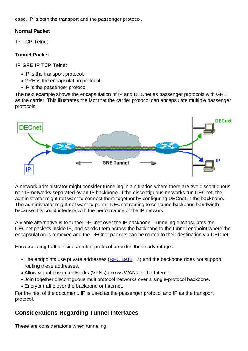
The next example shows the encapsulation of IP and DECnet as passenger protocols with GREas the carrier. This illustrates the fact that the carrier protocol can encapsulate multiple passengerprotocols.
A network administrator might consider tunneling in a situation where there are two discontiguousnon-IP networks separated by an IP backbone. If the discontiguous networks run DECnet, theadministrator might not want to connect them together by configuring DECnet in the backbone.The administrator might not want to permit DECnet routing to consume backbone bandwidthbecause this could interfere with the performance of the IP network.
A viable alternative is to tunnel DECnet over the IP backbone. Tunneling encapsulates theDECnet packets inside IP, and sends them across the backbone to the tunnel endpoint where theencapsulation is removed and the DECnet packets can be routed to their destination via DECnet.
Encapsulating traffic inside another protocol provides these advantages:
The endpoints use private addresses (RFC 1918 ) and the backbone does not supportrouting these addresses.
●
Allow virtual private networks (VPNs) across WANs or the Internet.●
Join together discontiguous multiprotocol networks over a single-protocol backbone.●
Encrypt traffic over the backbone or Internet.●
For the rest of the document, IP is used as the passenger protocol and IP as the transportprotocol.
Considerations Regarding Tunnel Interfaces
These are considerations when tunneling.
Fast switching of GRE tunnels was introduced in Cisco IOS Release 11.1 and CEF switchingwas introduced in version 12.0. CEF switching for multipoint GRE tunnels was introduced inversion 12.2(8)T. Encapsulation and decapsulation at tunnel endpoints were slow operationsin earlier versions of Cisco IOS when only process switching was supported.
●
There are security and topology issues when tunneling packets. Tunnels can bypass accesscontrol lists (ACLs) and firewalls. If you tunnel through a firewall, you basically bypass thefirewall for whatever passenger protocol you are tunneling. Therefore it is recommended toinclude firewall functionality at the tunnel endpoints to enforce any policy on the passengerprotocols.
●
Tunneling might create problems with transport protocols that have limited timers (forexample, DECnet) because of increased latency.
●
Tunneling across environments with different speed links, like fast FDDI rings and throughslow 9600-bps phone lines, might introduce packet reordering problems. Some passengerprotocols function poorly in mixed media networks.
●
Point-to-point tunnels can use up the bandwidth on a physical link. If you run routing protocolsover multiple point-to-point tunnels, keep in mind that each tunnel interface has a bandwidthand that the physical interface over which the tunnel runs has a bandwidth. For example, youwould want to set the tunnel bandwidth to 100 Kb if there were 100 tunnels running over a 10Mb link. The default bandwidth for a tunnel is 9Kb.
●
Routing protocols might prefer a tunnel over a "real" link because the tunnel might deceptivelyappear to be a one-hop link with the lowest cost path, although it actually involves more hopsand is really more costly than another path. This can be mitigated with proper configuration ofthe routing protocol. You might want to consider running a different routing protocol over thetunnel interface than the routing protocol running on the physical interface.
●
Problems with recursive routing can be avoided by configuring appropriate static routes to thetunnel destination. A recursive route is when the best path to the "tunnel destination" isthrough the tunnel itself. This situation causes the tunnel interface to bounce up and down.You will see this error when there is a recursive routing problem.%TUN-RECURDOWN InterfaceTunnel 0
temporarily disabled due to recursive routing
●
The Router as a PMTUD Participant at the Endpoint of a Tunnel
The router has two different PMTUD roles to play when it is the endpoint of a tunnel.
In the first role the router is the forwarder of a host packet. For PMTUD processing, the routerneeds to check the DF bit and packet size of the original data packet and take appropriateaction when necessary.
●
The second role comes into play after the router has encapsulated the original IP packetinside the tunnel packet. At this stage, the router acts more like a host with respect to PMTUDand in regards to the tunnel IP packet.
●
Lets start by looking at what happens when the router acts in the first role, a router that forwardshost IP packets, with respect to PMTUD. This role comes into play before the router encapsulatesthe host IP packet inside the tunnel packet.
If the router participates as the forwarder of a host packet it will complete these actions:
Check whether the DF bit is set.●
Check what size packet the tunnel can accommodate.●
Fragment (if packet is too large and DF bit is not set), encapsulate fragments and send; or●
Drop the packet (if packet is too large and DF bit is set) and send an ICMP message to thesender.
●
Encapsulate (if packet is not too large) and send.●
Generically, there is a choice of encapsulation and then fragmentation (send two encapsulationfragments) or fragmentation and then encapsulation (send two encapsulated fragments).
Some examples that describe the mechanics of IP packet encapsulation and fragmentation andtwo scenarios that show the interaction of PMTUD and packets that traverse example networksare detailed in this section.
The first example shows what happens to a packet when the router (at the tunnel source) acts inthe role of forwarding router. Remember that to process PMTUD, the router needs to check the DFbit and packet size of the original data packet and take appropriate action. This examples usesGRE encapsulation for the tunnel. As can be seen, GRE does fragmentation before encapsulation.Later examples show scenarios in which fragmentation is done after encapsulation.
In Example 1, the DF bit is not set (DF = 0) and the GRE tunnel IP MTU is 1476 (1500 - 24).
Example 1
The forwarding router (at the tunnel source) receives a 1500-byte datagram with the DF bitclear (DF = 0) from the sending host. This datagram is composed of a 20-byte IP header plusa 1480 byte TCP payload.
1.
Because the packet will be too large for the IP MTU after the GRE overhead (24 bytes) isadded, the forwarding router breaks the datagram into two fragments of 1476 (20 bytes IPheader + 1456 bytes IP payload) and 44 bytes (20 bytes of IP header + 24 bytes of IPpayload) so after the GRE encapsulation is added, the packet will not be larger than theoutgoing physical interface MTU.
2.
The forwarding router adds GRE encapsulation, which includes a 4-byte GRE header plus a20-byte IP header, to each fragment of the original IP datagram. These two IP datagramsnow have a length of 1500 and 68 bytes and these datagrams are seen as individual IPdatagrams, not as fragments.
3.
The tunnel destination router removes the GRE encapsulation from each fragment of theoriginal datagram, which leaves two IP fragments of lengths 1476 and 24 bytes. These IPdatagram fragments will be forwarded separately by this router to the receiving host.
4.
The receiving host will reassemble these two fragments into the original datagram.5.Scenario 5 depicts the role of the forwarding router in the context of a network topology.
In this example the router acts in the same role of forwarding router, but this time the DF bit is set(DF = 1).
Example 2
The forwarding router at the tunnel source receives a 1500-byte datagram with DF = 1 fromthe sending host.
1.
Since the DF bit is set, and the datagram size (1500 bytes) is greater than the GRE tunnel IPMTU (1476), the router will drop the datagram and send an "ICMP fragmentation needed butDF bit set" message to the source of the datagram. The ICMP message will alert the senderthat the MTU is 1476.
2.
The sending host receives the ICMP message, and when it resends the original data it willuse a 1476-byte IP datagram.
3.
This IP datagram length (1476 bytes) is now equal in value to the GRE tunnel IP MTU so therouter adds the GRE encapsulation to the IP datagram.
4.
The receiving router (at the tunnel destination) removes the GRE encapsulation of the IPdatagram and sends it to the receiving host.
5.
Now we can look at what happens when the router acts in the second role as a sending host withrespect to PMTUD and in regards to the tunnel IP packet. Recall that this role comes into playafter the router has encapsulated the original IP packet inside the tunnel packet.
Note: By default a router does not do PMTUD on the GRE tunnel packets that it generates.The tunnel path-mtu-discovery command can be used to turn on PMTUD for GRE-IPtunnel packets.
Example 3 shows what happens when the host sends IP datagrams that are small enough to fitwithin the IP MTU on the GRE Tunnel interface. The DF bit in this case can be either set or clear(1 or 0). The GRE tunnel interface does not have the tunnel path-mtu-discovery commandconfigured so the router will not do PMTUD on the GRE-IP packet.
Example 3
The forwarding router at the tunnel source receives a 1476-byte datagram from the sendinghost.
1.
This router encapsulates the 1476-byte IP datagram inside GRE to get a 1500-byte GRE IPdatagram. The DF bit in the GRE IP header will be clear (DF = 0). This router then forwardsthis packet to the tunnel destination.
2.
Assume there is a router between the tunnel source and destination with a link MTU of1400. This router will fragment the tunnel packet since the DF bit is clear (DF = 0).Remember that this example fragments the outermost IP, so the GRE, inner IP, and TCPheaders will only show up in the first fragment.
3.
The tunnel destination router must reassemble the GRE tunnel packet.4.After the GRE tunnel packet is reassembled, the router removes the GRE IP header andsends the original IP datagram on its way.
5.
The next example shows what happens when the router acts in the role of a sending host withrespect to PMTUD and in regards to the tunnel IP packet. This time the DF bit is set (DF = 1) inthe original IP header and the tunnel path-mtu-discovery command has been configured so thatthe DF bit will be copied from the inner IP header to the outer (GRE + IP) header.
Example 4
The forwarding router at the tunnel source receives a 1476-byte datagram with DF = 1 fromthe sending host.
1.
This router encapsulates the 1476-byte IP datagram inside GRE to get a 1500-byte GRE IPdatagram. This GRE IP header will have the DF bit set (DF = 1) since the original IPdatagram had the DF bit set. This router then forwards this packet to the tunnel destination.
2.
Again, assume there is a router between the tunnel source and destination with a link MTU of1400. This router will not fragment the tunnel packet since the DF bit is set (DF = 1). Thisrouter must drop the packet and send an ICMP error message to the tunnel source router,since that is the source IP address on the packet.
3.
The forwarding router at the tunnel source receives this ICMP error message and it will lowerthe GRE tunnel IP MTU to 1376 (1400 - 24). The next time the sending host retransmits thedata in a 1476-byte IP packet, this packet will be too large and this router will send an ICMPerror message to the sender with a MTU value of 1376. When the sending host retransmitsthe data, it will send it in a 1376-byte IP packet and this packet will make it through the GREtunnel to the receiving host.
4.
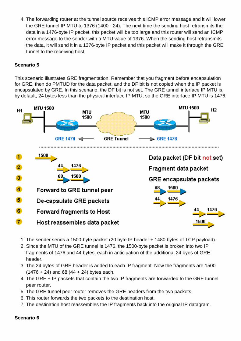
Scenario 5
This scenario illustrates GRE fragmentation. Remember that you fragment before encapsulationfor GRE, then do PMTUD for the data packet, and the DF bit is not copied when the IP packet isencapsulated by GRE. In this scenario, the DF bit is not set. The GRE tunnel interface IP MTU is,by default, 24 bytes less than the physical interface IP MTU, so the GRE interface IP MTU is 1476.
The sender sends a 1500-byte packet (20 byte IP header + 1480 bytes of TCP payload).1.Since the MTU of the GRE tunnel is 1476, the 1500-byte packet is broken into two IPfragments of 1476 and 44 bytes, each in anticipation of the additional 24 byes of GREheader.
2.
The 24 bytes of GRE header is added to each IP fragment. Now the fragments are 1500(1476 + 24) and 68 (44 + 24) bytes each.
3.
The GRE + IP packets that contain the two IP fragments are forwarded to the GRE tunnelpeer router.
4.
The GRE tunnel peer router removes the GRE headers from the two packets.5.This router forwards the two packets to the destination host.6.The destination host reassembles the IP fragments back into the original IP datagram.7.
Scenario 6
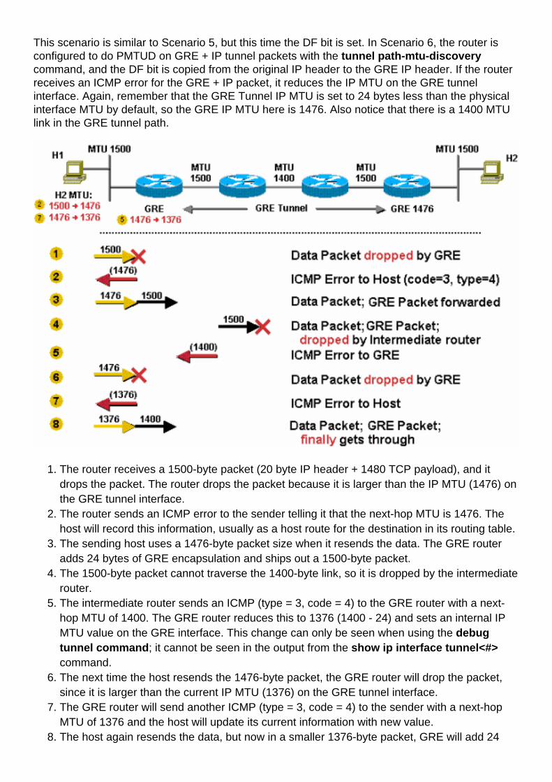
This scenario is similar to Scenario 5, but this time the DF bit is set. In Scenario 6, the router isconfigured to do PMTUD on GRE + IP tunnel packets with the tunnel path-mtu-discoverycommand, and the DF bit is copied from the original IP header to the GRE IP header. If the routerreceives an ICMP error for the GRE + IP packet, it reduces the IP MTU on the GRE tunnelinterface. Again, remember that the GRE Tunnel IP MTU is set to 24 bytes less than the physicalinterface MTU by default, so the GRE IP MTU here is 1476. Also notice that there is a 1400 MTUlink in the GRE tunnel path.
The router receives a 1500-byte packet (20 byte IP header + 1480 TCP payload), and itdrops the packet. The router drops the packet because it is larger than the IP MTU (1476) onthe GRE tunnel interface.
1.
The router sends an ICMP error to the sender telling it that the next-hop MTU is 1476. Thehost will record this information, usually as a host route for the destination in its routing table.
2.
The sending host uses a 1476-byte packet size when it resends the data. The GRE routeradds 24 bytes of GRE encapsulation and ships out a 1500-byte packet.
3.
The 1500-byte packet cannot traverse the 1400-byte link, so it is dropped by the intermediaterouter.
4.
The intermediate router sends an ICMP (type = 3, code = 4) to the GRE router with a next-hop MTU of 1400. The GRE router reduces this to 1376 (1400 - 24) and sets an internal IPMTU value on the GRE interface. This change can only be seen when using the debugtunnel command; it cannot be seen in the output from the show ip interface tunnel<#>command.
5.
The next time the host resends the 1476-byte packet, the GRE router will drop the packet,since it is larger than the current IP MTU (1376) on the GRE tunnel interface.
6.
The GRE router will send another ICMP (type = 3, code = 4) to the sender with a next-hopMTU of 1376 and the host will update its current information with new value.
7.
The host again resends the data, but now in a smaller 1376-byte packet, GRE will add 248.
bytes of encapsulation and forward it on. This time the packet will make it to the GRE tunnelpeer, where the packet will be decapsulated and sent to the destination host.Note: If thetunnel path-mtu-discovery command was not configured on the forwarding router in thisscenario, and the DF bit was set in the packets forwarded through the GRE tunnel, Host 1would still succeed in sending TCP/IP packets to Host 2, but they would get fragmented inthe middle at the 1400 MTU link. Also the GRE tunnel peer would have to reassemble thembefore it could decapsulate and forward them on.
"Pure" IPsec Tunnel Mode
The IP Security (IPsec) Protocol is a standards-based method that provides privacy, integrity, andauthenticity to information transferred across IP networks. IPsec provides IP network-layerencryption. IPsec lengthens the IP packet by adding at least one IP header (tunnel mode). Theadded header(s) varies in length dependent on the IPsec configuration mode but they do notexceed ~58 bytes (Encapsulating Security Payload (ESP) and ESP authentication (ESPauth)) perpacket.
IPsec has two modes, tunnel mode and transport mode.
Tunnel mode is the default mode. With tunnel mode, the entire original IP packet is protected(encrypted, authenticated, or both) and encapsulated by the IPsec headers and trailers. Thena new IP header is prepended to the packet, which specifes the IPsec endpoints (peers) asthe source and destination. Tunnel mode can be used with any unicast IP traffic and must beused if IPsec is protecting traffic from hosts behind the IPsec peers. For example, tunnelmode is used with Virtual Private Networks (VPNs) where hosts on one protected networksend packets to hosts on a different protected network via a pair of IPsec peers. With VPNs,the IPsec "tunnel" protects the IP traffic between hosts by encrypting this traffic between theIPsec peer routers.
●
With transport mode (configured with the subcommand, mode transport, on the transformdefinition), only the payload of the original IP packet is protected (encrypted, authenticated, orboth). The payload is encapsulated by the IPsec headers and trailers. The original IP headersremain intact, except that the IP protocol field is changed to be ESP (50), and the originalprotocol value is saved in the IPsec trailer to be restored when the packet is decrypted.Transport mode is used only when the IP traffic to be protected is between the IPsec peersthemselves, the source and destination IP addresses on the packet are the same as the IPsecpeer addresses. Normally IPsec transport mode is only used when another tunneling protocol(like GRE) is used to first encapsulate the IP data packet, then IPsec is used to protect theGRE tunnel packets.
●
IPsec always does PMTUD for data packets and for its own packets. There are IPsecconfiguration commands to modify PMTUD processing for the IPsec IP packet, IPsec can clear,set, or copy the DF bit from the data packet IP header to the IPsec IP header. This is called the"DF Bit Override Functionality" feature.
Note: You really want to avoid fragmentation after encapsulation when you do hardwareencryption with IPsec. Hardware encryption can give you throughput of about 50 Mbsdepending on the hardware, but if the IPsec packet is fragmented you loose 50 to 90 percentof the throughput. This loss is because the fragmented IPsec packets are process-switchedfor reassembly and then handed to the Hardware encryption engine for decryption. This loss
of throughput can bring hardware encryption throughput down to the performance level ofsoftware encryption (2-10 Mbs).
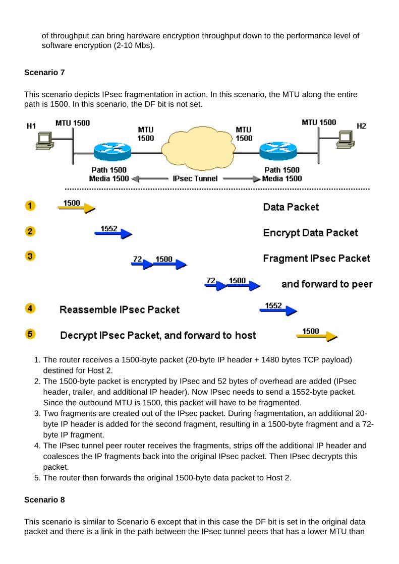
Scenario 7
This scenario depicts IPsec fragmentation in action. In this scenario, the MTU along the entirepath is 1500. In this scenario, the DF bit is not set.
The router receives a 1500-byte packet (20-byte IP header + 1480 bytes TCP payload)destined for Host 2.
1.
The 1500-byte packet is encrypted by IPsec and 52 bytes of overhead are added (IPsecheader, trailer, and additional IP header). Now IPsec needs to send a 1552-byte packet.Since the outbound MTU is 1500, this packet will have to be fragmented.
2.
Two fragments are created out of the IPsec packet. During fragmentation, an additional 20-byte IP header is added for the second fragment, resulting in a 1500-byte fragment and a 72-byte IP fragment.
3.
The IPsec tunnel peer router receives the fragments, strips off the additional IP header andcoalesces the IP fragments back into the original IPsec packet. Then IPsec decrypts thispacket.
4.
The router then forwards the original 1500-byte data packet to Host 2.5.
Scenario 8
This scenario is similar to Scenario 6 except that in this case the DF bit is set in the original datapacket and there is a link in the path between the IPsec tunnel peers that has a lower MTU than
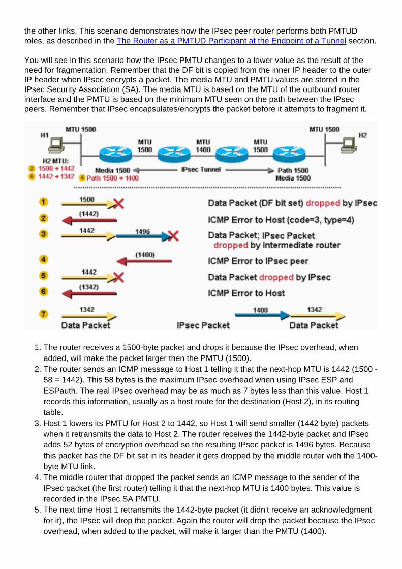
the other links. This scenario demonstrates how the IPsec peer router performs both PMTUDroles, as described in the The Router as a PMTUD Participant at the Endpoint of a Tunnel section.
You will see in this scenario how the IPsec PMTU changes to a lower value as the result of theneed for fragmentation. Remember that the DF bit is copied from the inner IP header to the outerIP header when IPsec encrypts a packet. The media MTU and PMTU values are stored in theIPsec Security Association (SA). The media MTU is based on the MTU of the outbound routerinterface and the PMTU is based on the minimum MTU seen on the path between the IPsecpeers. Remember that IPsec encapsulates/encrypts the packet before it attempts to fragment it.
The router receives a 1500-byte packet and drops it because the IPsec overhead, whenadded, will make the packet larger then the PMTU (1500).
1.
The router sends an ICMP message to Host 1 telling it that the next-hop MTU is 1442 (1500 -58 = 1442). This 58 bytes is the maximum IPsec overhead when using IPsec ESP andESPauth. The real IPsec overhead may be as much as 7 bytes less than this value. Host 1records this information, usually as a host route for the destination (Host 2), in its routingtable.
2.
Host 1 lowers its PMTU for Host 2 to 1442, so Host 1 will send smaller (1442 byte) packetswhen it retransmits the data to Host 2. The router receives the 1442-byte packet and IPsecadds 52 bytes of encryption overhead so the resulting IPsec packet is 1496 bytes. Becausethis packet has the DF bit set in its header it gets dropped by the middle router with the 1400-byte MTU link.
3.
The middle router that dropped the packet sends an ICMP message to the sender of theIPsec packet (the first router) telling it that the next-hop MTU is 1400 bytes. This value isrecorded in the IPsec SA PMTU.
4.
The next time Host 1 retransmits the 1442-byte packet (it didn't receive an acknowledgmentfor it), the IPsec will drop the packet. Again the router will drop the packet because the IPsecoverhead, when added to the packet, will make it larger than the PMTU (1400).
5.
The router sends an ICMP message to Host 1 telling it that the next-hop MTU is now 1342.(1400 - 58 = 1342). Host 1 will again record this information.
6.
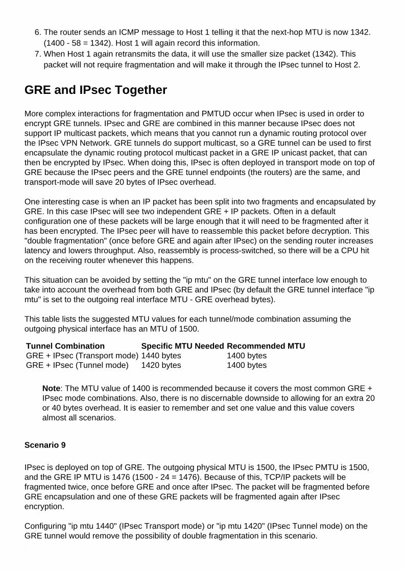
When Host 1 again retransmits the data, it will use the smaller size packet (1342). Thispacket will not require fragmentation and will make it through the IPsec tunnel to Host 2.
7.
GRE and IPsec Together
More complex interactions for fragmentation and PMTUD occur when IPsec is used in order toencrypt GRE tunnels. IPsec and GRE are combined in this manner because IPsec does notsupport IP multicast packets, which means that you cannot run a dynamic routing protocol overthe IPsec VPN Network. GRE tunnels do support multicast, so a GRE tunnel can be used to firstencapsulate the dynamic routing protocol multicast packet in a GRE IP unicast packet, that canthen be encrypted by IPsec. When doing this, IPsec is often deployed in transport mode on top ofGRE because the IPsec peers and the GRE tunnel endpoints (the routers) are the same, andtransport-mode will save 20 bytes of IPsec overhead.
One interesting case is when an IP packet has been split into two fragments and encapsulated byGRE. In this case IPsec will see two independent GRE + IP packets. Often in a defaultconfiguration one of these packets will be large enough that it will need to be fragmented after ithas been encrypted. The IPsec peer will have to reassemble this packet before decryption. This"double fragmentation" (once before GRE and again after IPsec) on the sending router increaseslatency and lowers throughput. Also, reassembly is process-switched, so there will be a CPU hiton the receiving router whenever this happens.
This situation can be avoided by setting the "ip mtu" on the GRE tunnel interface low enough totake into account the overhead from both GRE and IPsec (by default the GRE tunnel interface "ipmtu" is set to the outgoing real interface MTU - GRE overhead bytes).
This table lists the suggested MTU values for each tunnel/mode combination assuming theoutgoing physical interface has an MTU of 1500.
Tunnel Combination Specific MTU Needed Recommended MTUGRE + IPsec (Transport mode) 1440 bytes 1400 bytesGRE + IPsec (Tunnel mode) 1420 bytes 1400 bytes
Note: The MTU value of 1400 is recommended because it covers the most common GRE +IPsec mode combinations. Also, there is no discernable downside to allowing for an extra 20or 40 bytes overhead. It is easier to remember and set one value and this value coversalmost all scenarios.
Scenario 9
IPsec is deployed on top of GRE. The outgoing physical MTU is 1500, the IPsec PMTU is 1500,and the GRE IP MTU is 1476 (1500 - 24 = 1476). Because of this, TCP/IP packets will befragmented twice, once before GRE and once after IPsec. The packet will be fragmented beforeGRE encapsulation and one of these GRE packets will be fragmented again after IPsecencryption.
Configuring "ip mtu 1440" (IPsec Transport mode) or "ip mtu 1420" (IPsec Tunnel mode) on theGRE tunnel would remove the possibility of double fragmentation in this scenario.

The router receives a 1500-byte datagram.1.Before encapsulation, GRE fragments the 1500-byte packet into two pieces, 1476 (1500 - 24= 1476) and 44 (24 data + 20 IP header) bytes.
2.
GRE encapsulates the IP fragments, which adds 24 bytes to each packet. This results in twoGRE + IPsec packets of 1500 (1476 + 24 = 1500) and 68 (44 + 24) bytes each.
3.
IPsec encrypts the two packets, adding 52 byes (IPsec tunnel-mode) of encapsulationoverhead to each, in order to give a 1552-byte and a 120-byte packet.
4.
The 1552-byte IPsec packet is fragmented by the router because it is larger than theoutbound MTU (1500). The 1552-byte packet is split into pieces, a 1500-byte packet and a72-byte packet (52 bytes "payload" plus an additional 20-byte IP header for the secondfragment). The three packets 1500-byte, 72-byte, and 120-byte packets are forwarded to theIPsec + GRE peer.
5.
The receiving router reassembles the two IPsec fragments (1500 bytes and 72 bytes) inorder to get the original 1552-byte IPsec + GRE packet. Nothing needs to be done to the120-byte IPsec + GRE packet.
6.
IPsec decrypts both 1552-byte and 120-byte IPsec + GRE packets in order to get 1500-byteand 68-byte GRE packets.
7.
GRE decapsulates the 1500-byte and 68-byte GRE packets in order to get 1476-byte and44-byte IP packet fragments. These IP packet fragments are forwarded to the destinationhost.
8.
Host 2 reassembles these IP fragments in order to get the original 1500-byte IP datagram.9.Scenario 10 is similar to Scenario 8 except there is a lower MTU link in the tunnel path. This is a"worst case" scenario for the first packet sent from Host 1 to Host 2. After the last step in thisscenario, Host 1 sets the correct PMTU for Host 2 and all is well for the TCP connections betweenHost 1 and Host 2. TCP flows between Host 1 and other hosts (reachable via the IPsec + GREtunnel) will only have to go through the last three steps of Scenario 10.
In this scenario, the tunnel path-mtu-discovery command is configured on the GRE tunnel andthe DF bit is set on TCP/IP packets that originate from Host 1.
Scenario 10
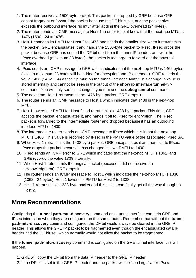
The router receives a 1500-byte packet. This packet is dropped by GRE because GREcannot fragment or forward the packet because the DF bit is set, and the packet sizeexceeds the outbound interface "ip mtu" after adding the GRE overhead (24 bytes).
1.
The router sends an ICMP message to Host 1 in order to let it know that the next-hop MTU is1476 (1500 - 24 = 1476).
2.
Host 1 changes its PMTU for Host 2 to 1476 and sends the smaller size when it retransmitsthe packet. GRE encapsulates it and hands the 1500-byte packet to IPsec. IPsec drops thepacket because GRE has copied the DF bit (set) from the inner IP header, and with theIPsec overhead (maximum 38 bytes), the packet is too large to forward out the physicalinterface.
3.
IPsec sends an ICMP message to GRE which indicates that the next-hop MTU is 1462 bytes(since a maximum 38 bytes will be added for encryption and IP overhead). GRE records thevalue 1438 (1462 - 24) as the "ip mtu" on the tunnel interface.Note: This change in value isstored internally and cannot be seen in the output of the show ip interface tunnel<#>command. You will only see this change if you turn use the debug tunnel command.
4.
The next time Host 1 retransmits the 1476-byte packet, GRE drops it.5.The router sends an ICMP message to Host 1 which indicates that 1438 is the next-hopMTU.
6.
Host 1 lowers the PMTU for Host 2 and retransmits a 1438-byte packet. This time, GREaccepts the packet, encapsulates it, and hands it off to IPsec for encryption. The IPsecpacket is forwarded to the intermediate router and dropped because it has an outboundinterface MTU of 1400.
7.
The intermediate router sends an ICMP message to IPsec which tells it that the next-hopMTU is 1400. This value is recorded by IPsec in the PMTU value of the associated IPsec SA.
8.
When Host 1 retransmits the 1438-byte packet, GRE encapsulates it and hands it to IPsec.IPsec drops the packet because it has changed its own PMTU to 1400.
9.
IPsec sends an ICMP error to GRE which indicates that the next-hop MTU is 1362, andGRE records the value 1338 internally.
10.
When Host 1 retransmits the original packet (because it did not receive anacknowledgment), GRE drops it.
11.
The router sends an ICMP message to Host 1 which indicates the next-hop MTU is 1338(1362 - 24 bytes). Host 1 lowers its PMTU for Host 2 to 1338.
12.
Host 1 retransmits a 1338-byte packet and this time it can finally get all the way through toHost 2.
13.
More Recommendations
Configuring the tunnel path-mtu-discovery command on a tunnel interface can help GRE andIPsec interaction when they are configured on the same router. Remember that without the tunnelpath-mtu-discovery command configured, the DF bit would always be cleared in the GRE IPheader. This allows the GRE IP packet to be fragmented even though the encapsulated data IPheader had the DF bit set, which normally would not allow the packet to be fragmented.
If the tunnel path-mtu-discovery command is configured on the GRE tunnel interface, this willhappen.
GRE will copy the DF bit from the data IP header to the GRE IP header.1.If the DF bit is set in the GRE IP header and the packet will be "too large" after IPsec2.
encryption for the IP MTU on the physical outgoing interface, then IPsec will drop the packetand notify the GRE tunnel to reduce its IP MTU size.IPsec does PMTUD for its own packets and if the IPsec PMTU changes (if it is reduced),then IPsec does not immediately notify GRE, but when another "too large" packet comesthorough, then the process in step 2 occurs.
3.
GRE's IP MTU is now smaller, so it will drop any data IP packets with the DF bit set that arenow too large and send an ICMP message to the sending host.
4.
The tunnel path-mtu-discovery command helps the GRE interface set its IP MTU dynamically,rather than statically with the ip mtu command. It is actually recommended that both commandsare used. The ip mtu command is used to provide room for the GRE and IPsec overhead relativeto the local physical outgoing interface IP MTU. The tunnel path-mtu-discovery command allowsthe GRE tunnel IP MTU to be further reduced if there is a lower IP MTU link in the path betweenthe IPsec peers.
Below are some of the things you can do if you are having problems with PMTUD in a networkwhere there are GRE + IPsec tunnels configured.
This list begins with the most desirable solution.
Fix the problem with PMTUD not working, which is usually caused by a router or firewall thatblocks ICMP.
●
Use the ip tcp adjust-mss command on the tunnel interfaces so that the router will reducethe TCP MSS value in the TCP SYN packet. This will help the two end hosts (the TCP senderand receiver) to use packets small enough so that PMTUD is not needed.
●
Use policy routing on the ingress interface of the router and configure a route map to clear theDF bit in the data IP header before it gets to the GRE tunnel interface. This will allow the dataIP packet to be fragmented before GRE encapsulation.
●
Increase the "ip mtu" on the GRE tunnel interface to be equal to the outbound interface MTU.This will allow the data IP packet to be GRE encapsulated without fragmenting it first. TheGRE packet will then be IPsec encrypted and then fragmented to go out the physicaloutbound interface. In this case you would not configure tunnel path-mtu-discoverycommand on the GRE tunnel interface. This can dramatically reduce the throughput becauseIP packet reassembly on the IPsec peer is done in process-switching mode.
●
Related Information
IP Routing Support Page●
IPSec (IP Security Protocol) Support Page●
IPSec Overhead Calculator (Calculate Packet Size with IPSec Encapsulation Protocols)●
RFC 1191 Path MTU Discovery ●
RFC 1063 IP MTU Discovery Options ●
RFC 791 Internet Protocol ●
RFC 793 Transmission Control Protocol ●
RFC 879 The TCP Maximum Segment Size and Related Topics ●
RFC 1701 Generic Routing Encapsulation (GRE) ●
RFC 1241 A Scheme for an Internet Encapsulation Protocol ●
RFC 2003 IP Encapsulation within IP ●
Technical Support - Cisco Systems●


![How a Large ATM MTU Causes Deadlocks in TCP Data Transfers€¦ · network MTU (maximum transmission unit)—to compute the maximum segment size (MSS) 16], [7]. In our measurements](https://img.pdfslide.us/doc/110x75/5f7df686f179842862411c20/how-a-large-atm-mtu-causes-deadlocks-in-tcp-data-network-mtu-maximum-transmission.jpg)