Embed Size (px)
Citation preview

Intarea Working Group R. BonicaInternet-Draft Juniper NetworksIntended status: Best Current Practice C. PignataroExpires: January 3, 2015 Cisco Systems J. Touch USC/ISI July 2, 2014
A Fragmentation Strategy for Generic Routing Encapsulation (GRE) draft-bonica-intarea-gre-mtu-05
Abstract
This memo specifies a default GRE tunnel fragmentation strategy, which has been implemented by many vendors and widely deployed on the Internet.
This memo also specifies requirements for GRE implementations. Having satisfied these requirements, a GRE implementation will execute the default GRE tunnel fragmentation strategy, specified herein, with minimal configuration. However, with additional configuration, the GRE implementation can execute any of the tunnel fragmentation strategies defined in RFC 4459.
Requirements Language
The key words "MUST", "MUST NOT", "REQUIRED", "SHALL", "SHALL NOT", "SHOULD", "SHOULD NOT", "RECOMMENDED", "MAY", and "OPTIONAL" in this document are to be interpreted as described in RFC 2119 [RFC2119].
Status of This Memo
This Internet-Draft is submitted in full conformance with the provisions of BCP 78 and BCP 79.
Internet-Drafts are working documents of the Internet Engineering Task Force (IETF). Note that other groups may also distribute working documents as Internet-Drafts. The list of current Internet- Drafts is at http://datatracker.ietf.org/drafts/current/.
Internet-Drafts are draft documents valid for a maximum of six months and may be updated, replaced, or obsoleted by other documents at any time. It is inappropriate to use Internet-Drafts as reference material or to cite them other than as "work in progress."
This Internet-Draft will expire on January 3, 2015.
Bonica, et al. Expires January 3, 2015 [Page 1]

Internet-Draft GRE Fragmentation July 2014
Copyright Notice
Copyright (c) 2014 IETF Trust and the persons identified as the document authors. All rights reserved.
This document is subject to BCP 78 and the IETF Trust’s Legal Provisions Relating to IETF Documents (http://trustee.ietf.org/license-info) in effect on the date of publication of this document. Please review these documents carefully, as they describe your rights and restrictions with respect to this document. Code Components extracted from this document must include Simplified BSD License text as described in Section 4.e of the Trust Legal Provisions and are provided without warranty as described in the Simplified BSD License.
Table of Contents
1. Introduction . . . . . . . . . . . . . . . . . . . . . . . . 2 1.1. Terminology . . . . . . . . . . . . . . . . . . . . . . . 3 2. Strategic Overview . . . . . . . . . . . . . . . . . . . . . 5 2.1. Candidate Strategies . . . . . . . . . . . . . . . . . . 5 2.2. Default Strategy . . . . . . . . . . . . . . . . . . . . 6 3. Generic Requirements for GRE Ingress Routers . . . . . . . . 6 3.1. General . . . . . . . . . . . . . . . . . . . . . . . . . 6 3.2. GRE MTU (GMTU) Estimation and Discovery . . . . . . . . . 6 4. Procedures Affecting The GRE Deliver Header . . . . . . . . . 7 4.1. Tunneling GRE Over IPv4 . . . . . . . . . . . . . . . . . 7 4.2. Tunneling GRE Over IPv6 . . . . . . . . . . . . . . . . . 8 5. Procedures Affecting the GRE Payoad . . . . . . . . . . . . . 8 5.1. IPv4 Payloads . . . . . . . . . . . . . . . . . . . . . . 8 5.2. IPv6 Payloads . . . . . . . . . . . . . . . . . . . . . . 8 5.3. MPLS Payloads . . . . . . . . . . . . . . . . . . . . . . 8 6. GRE Egress Router Procedures . . . . . . . . . . . . . . . . 8 7. IANA Considerations . . . . . . . . . . . . . . . . . . . . . 9 8. Security Considerations . . . . . . . . . . . . . . . . . . . 9 9. Acknowledgements . . . . . . . . . . . . . . . . . . . . . . 9 10. References . . . . . . . . . . . . . . . . . . . . . . . . . 9 10.1. Normative References . . . . . . . . . . . . . . . . . . 9 10.2. Informative References . . . . . . . . . . . . . . . . . 10 Authors’ Addresses . . . . . . . . . . . . . . . . . . . . . . . 10
1. Introduction
Generic Routing Encapsulation (GRE) [RFC2784] [RFC2890] can be used to carry any network layer protocol over any network layer protocol. GRE has been implemented by many vendors and is widely deployed in the Internet.
Bonica, et al. Expires January 3, 2015 [Page 2]

Internet-Draft GRE Fragmentation July 2014
The GRE specification, by design, does not describe procedures to address fragmentation. Lacking guidance from the specification, vendors have developed implementation-specific fragmentation strategies. Because fragmentation procedures are local to the GRE ingress router, devices implementing one fragmentation strategy can interoperate with devices that implement another fragmentation strategy. Operational experience has demonstrated the relative merits of each strategy. [RFC4459] describes several fragmentation strategies and evaluates the relative merits of each.
This memo reviews the fragmentation strategies presented in [RFC4459]. It also specifies a default GRE tunnel fragmentation strategy, which has been implemented by many vendors and widely deployed on the Internet.
Finally, this memo specifies requirements for GRE implementations. Having satisfied these requirements, a GRE implementation will execute the default GRE tunnel fragmentation strategy, specified herein, with minimal configuration. However, with additional configuration, the GRE implementation can execute any of the strategies defined in[RFC4459].
This memo specifies requirements beyond those stated in [RFC2784]. However, it does not update [RFC2784]. Therefore, a GRE implementation can comply with [RFC2784] without satisfying the requirements of this memo.
This memo addresses point-to-point unicast GRE tunnels that carry IPv4, IPv6 or MPLS payloads. All other tunnel types are beyond the scope of this document.
1.1. Terminology
The following terms are specific to GRE and are taken from [RFC2784]:
o GRE delivery header - an IPv4 or IPv6 header whose source address is that of the GRE ingress and whose destination address is that of the GRE egress. The GRE delivery header encapsulates a GRE header.
o GRE header - the GRE protocol header. The GRE header is encapsulated in the GRE delivery header and encapsulates GRE payload.
o GRE payload - a network layer packet that is encapsulated by the GRE header. The GRE payload can be IPv4, IPv6 or MPLS. Procedures for encapsulating IPv4 and IPv6 in GRE are described in [RFC2784] and [RFC2890]. Procedures for encapsulating MPLS in GRE
Bonica, et al. Expires January 3, 2015 [Page 3]

Internet-Draft GRE Fragmentation July 2014
are described in [RFC4023]. While other protocols may be delivered over GRE, they are beyond the scope of this document.
o GRE delivery packet - A packet containing a GRE delivery header, a GRE header, and GRE payload.
o GRE payload header - the IPv4, IPv6 or MPLS header of the GRE payload
o GRE overhead - the combined size of the GRE delivery header and the GRE header, measured in octets
The following terms are specific MTU discovery:
o link MTU (LMTU) - the maximum transmission unit, i.e., maximum packet size in octets, that can be conveyed over a link. LMTU is a unidirectional metric. A bidirectional link may be characterized by one LMTU in the forward direction and another MTU in the reverse direction.
o path MTU (PMTU) - the minimum LMTU of all the links in a path between a source node and a destination node. If the source and destination node are connected through an equal cost multipath (ECMP), the PMTU is equal to the minimum LMTU of all links contributing to the multipath.
o GRE MTU (GMTU) - the maximum transmission unit, i.e., maximum packet size in octets, that can be conveyed over a GRE tunnel without fragmentation of any kind. The GMTU is equal to the PMTU associated with the path between the tunnel ingress and the tunnel egress, minus the GRE overhead
o Path MTU Discovery (PMTUD) - A procedure for dynamically discovering the PMTU between two nodes on the Internet. PMTUD procedures rely on a router’s ability to deliver ICMP [RFC0792] [RFC4443] feedback to the host that originated a packet. PMTUD procedures for IPv4 are defined in [RFC1191]. PMTUD procedures for IPv6 are defined in [RFC1981].
o Packetization Layer PMTU Discovery (PLPMTUD) - An alternative to PMTUD that is designed to operate correctly in the absence of ICMP feedback from a router to the host that originated a packet. PLPMTUD procedures are defined in [RFC4821].
The following terms are introduced by this memo:
o fragmentable packet - An IPv4 packet with DF-bit equal to 0 and whose payload is larger than 64 bytes
Bonica, et al. Expires January 3, 2015 [Page 4]

Internet-Draft GRE Fragmentation July 2014
o ICMP Packet Too Big (PTB) message - an ICMPv4 [RFC0792] Destination Unreachable message with code equal to 4 (fragmentation needed and DF set) or an ICMPv6 [RFC4443] Packet Too Big message
2. Strategic Overview
2.1. Candidate Strategies
Section 3 of [RFC4459] identifies several strategies that a tunnel ingress router can execute in order to prevent payload packets with size greater than the GMTU from being black-holed inside of a tunnel. When applied to GRE, these actions are:
1. Discard the payload packet and send an ICMP PTB message to the payload source. The ICMP PTB message specifies the GMTU associated with the GRE tunnel. Upon receipt of the ICMP PTB message, the payload source revises its estimate of the PMTU associated with the payload destination. As a result, the payload source refrains from sending packets to that destination with size greater than the GMTU.
2. Fragment the payload packet and encapsulate each fragment within a complete GRE header and GRE delivery header.
3. Encapsulate the payload packet in a single GRE header and GRE delivery header. If the GRE payload is fragmentable and the GRE delivery header is IPv4, set the DF-bit on the GRE delivery header to 0, allowing the GRE delivery packet to be fragmented downstream. Also, if the delivery packet is IPv4 or IPv6 and the GRE delivery packet size exceeds the GMTU, fragment the GRE delivery packet.
In Strategies 1) and 2) the GRE payload packet is fragmented, and the task of reassembly is assigned to the payload destination. By contrast, in Strategy 3) the GRE delivery packet is fragmented, and the task of reassembly is assigned to the GRE egress router. In scenarios where the GRE egress router is not known to have sufficient compute and memory resources to support reassembly, Strategies 1) and 2) are preferable to Strategy 3).
However, Strategy 1) is effective only if the payload source executes PMTUD procedures and the GRE ingress router can deliver ICMP PTB messages to the payload source. In scenarios where the payload source does not execute PMTUD procedures or the GRE ingress router cannot deliver ICMP PTB messages to the payload source , Strategies 2) and 3) are preferable to Strategy 1).
Bonica, et al. Expires January 3, 2015 [Page 5]

Internet-Draft GRE Fragmentation July 2014
Strategy 2) is applicable only when the GRE payload is fragmentable. In all other cases, Strategies 1) or 3) are required.
Finally, Strategies 1) and 2) are effective only if the GRE ingress router maintains a sufficiently conservative estimate of the GMTU. Likewise, Strategy 3) is effective only if the GRE ingress router maintains a sufficiently conservative estimate of the GMTU or the GRE delivery packet is IPv4. Therefore, Strategy 3) is preferable to Strategies 1) and 2) when the GRE ingress router does not maintain a sufficiently conservative estimate of the GMTU and the GRE delivery header is IPv4.
2.2. Default Strategy
This section describes a default GRE fragmentation strategy that has been implemented by many vendors and has been widely deployed on the Internet.
When the GRE ingress router receives a non-fragmentable payload packet with length greater than the GMTU, the GRE ingress router discards the packet and sends an ICMP PTB message to the payload source. Upon receipt of the ICMP PTB message, the payload source revises its estimate of the PMTU associated with the payload destination. As a result, the payload source refrains from sending packets to that destination with size greater than the GMTU. See Strategy 1), above.
When the GRE ingress router receives a fragmentable packet with length greater than the GMTU, if fragments the payload packet and encapsulates each fragment within a complete GRE header and GRE delivery header. See Strategy 2), above.
3. Generic Requirements for GRE Ingress Routers
3.1. General
GRE ingress routers MUST satisfy all of the requirements stated in [RFC2784].
3.2. GRE MTU (GMTU) Estimation and Discovery
GRE ingress routers MUST support a configuration option through which a PMTU estimate can be associated with a GRE tunnel. The PMTU estimate reflects an estimate of the PMTU that the GRE ingress router associates with the GRE egress router. The default value of this configuration item MUST be less than or equal to the LMTU of the next-hop to the GRE egress router. However, GRE ingress routers MUST
Bonica, et al. Expires January 3, 2015 [Page 6]

Internet-Draft GRE Fragmentation July 2014
permit network operators to explicitly configure this value to be greater or less than its default.
GRE ingress routers SHOULD execute either PMTUD or PLPMTUD procedures to further refine their PMTU estimate. However, if an implementation supports PMTUD or PLPMTUD for GRE tunnels, it MUST include a configuration option that disables those procedures. This configuration option may be required to mitigate certain denial of service attacks (see Section 8).
GRE ingress routers MUST set the GMTU estimate to a value that is less than or equal to the PMTU estimate minus the GRE overhead. The ingress router’s GMTU estimate will not always reflect the actual GMTU. It is only an estimate. When the GMTU associated with a tunnel changes, the tunnel ingress router will not discover that change immediately. Likewise, if the ingress router performs PMTUD procedures and tunnel interior routers cannot deliver ICMP feedback to the tunnel ingress, GMTU estimates may be inaccurate.
4. Procedures Affecting The GRE Deliver Header
4.1. Tunneling GRE Over IPv4
By default, the GRE ingress router MUST set the DF-bit in the delivery header to 1 (Don’t Fragment). However, the GRE ingress router MUST support a configuration option that invokes the following behavior:
o when the GRE payload is IPv6, the DF-bit on the delivery header is set to 0 (Fragments Allowed)
o when the GRE payload is IPv4, the DF-bit value is copied from the payload header to the delivery header
When the DF-bit on the delivery header is set to 0, the GRE delivery packet may be fragmented by any router between the GRE ingress and egress and the GRE delivery packet will be reassembled by the GRE egress.
By default, the GRE ingress router MUST NOT emit a delivery header with MF-bit equal to 1 (More Fragments) or Offset greater than 0. However, the GRE ingress router MAY include a configuration option that allows this.
Bonica, et al. Expires January 3, 2015 [Page 7]

Internet-Draft GRE Fragmentation July 2014
4.2. Tunneling GRE Over IPv6
By default, the GRE ingress router MUST NOT emit a delivery header containing a fragment header. However, the GRE ingress router MAY include a configuration option that allows this.
5. Procedures Affecting the GRE Payoad
This section defines procedures that GRE ingress routers execute when they receive a packet a) whose next-hop is a GRE tunnel and b) whose size is greater than the GMTU associated with that tunnel.
5.1. IPv4 Payloads
If the payload is non-fragmentable, the GRE ingress router MUST discard the packet and send an ICMPv4 Destination Unreachable message to the payload source, with code equal to 4 (fragmentation needed and DF set). The ICMP Destination Unreachable message MUST contain an Next-hop MTU (as specified by [RFC1191]) and the next-hop MTU MUST be equal to the GMTU associated with the tunnel.
If the payload is fragmentable, the GRE ingress router MUST fragment the payload and submit each fragment to GRE tunnel. Therefore, the GRE egress router will receive complete, non-fragmented packets, containing fragmented payloads. The GRE egress router will forward the payload fragments to their ultimate destination where they will be reassembled.
5.2. IPv6 Payloads
The GRE ingress router MUST discard the packet and send an ICMPv6 [RFC4443] Packet Too Big message to the payload source. The MTU specified in the Packet Too Big message MUST be equal to the GMTU associated with the tunnel.
5.3. MPLS Payloads
The GRE ingress router MUST discard the packet. As it is impossible to reliably identify the payload source, the GRE ingress router MUST NOT attempt to send an ICMPv4 Destination Unreachable message or an ICMPv6 Packet Too Big message to the payload source.
6. GRE Egress Router Procedures
This section defines procedures that all GRE egress routers must execute.
Bonica, et al. Expires January 3, 2015 [Page 8]

Internet-Draft GRE Fragmentation July 2014
If the GRE egress router reassembles packets carrying GRE payloads, it MUST process the Explicit Congestion Notification (ECN) bits as described in Section 5.3 of [RFC3168].
7. IANA Considerations
This document makes no request of IANA.
8. Security Considerations
PMTU Discovery is vulnerable to two denial of service attacks (see Section 8 of [RFC1191] for details). Both attacks are based upon on a malicious party sending forged ICMPv4 Destination Unreachable or ICMPv6 Packet Too Big messages to a host. In the first attack, the forged message indicates an inordinately small PMTU. In the second attack, the forged message indicates an inordinately large MTU. In both cases, throughput is adversely affected. On order to mitigate such attacks, GRE implementations MUST include a configuration option to disable PMTU discovery on GRE tunnels. Also, they MAY include a configuration option that conditions the behavior of PMTUD to establish a minimum PMTU.
9. Acknowledgements
The authors would like to thank Fred Baker, Fred Detienne, Jagadish Grandhi, Jeff Haas, Vanitha Neelamegam, John Scudder, Mike Sullenberger and Wen Zhang for their constructive comments. The authors also express their gratitude to an anonymous donor, without whom this document would not have been written.
10. References
10.1. Normative References
[RFC0791] Postel, J., "Internet Protocol", STD 5, RFC 791, September 1981.
[RFC0792] Postel, J., "Internet Control Message Protocol", STD 5, RFC 792, September 1981.
[RFC1191] Mogul, J. and S. Deering, "Path MTU discovery", RFC 1191, November 1990.
[RFC1981] McCann, J., Deering, S., and J. Mogul, "Path MTU Discovery for IP version 6", RFC 1981, August 1996.
[RFC2119] Bradner, S., "Key words for use in RFCs to Indicate Requirement Levels", BCP 14, RFC 2119, March 1997.
Bonica, et al. Expires January 3, 2015 [Page 9]

Internet-Draft GRE Fragmentation July 2014
[RFC2460] Deering, S. and R. Hinden, "Internet Protocol, Version 6 (IPv6) Specification", RFC 2460, December 1998.
[RFC2784] Farinacci, D., Li, T., Hanks, S., Meyer, D., and P. Traina, "Generic Routing Encapsulation (GRE)", RFC 2784, March 2000.
[RFC2890] Dommety, G., "Key and Sequence Number Extensions to GRE", RFC 2890, September 2000.
[RFC3168] Ramakrishnan, K., Floyd, S., and D. Black, "The Addition of Explicit Congestion Notification (ECN) to IP", RFC 3168, September 2001.
[RFC4023] Worster, T., Rekhter, Y., and E. Rosen, "Encapsulating MPLS in IP or Generic Routing Encapsulation (GRE)", RFC 4023, March 2005.
[RFC4443] Conta, A., Deering, S., and M. Gupta, "Internet Control Message Protocol (ICMPv6) for the Internet Protocol Version 6 (IPv6) Specification", RFC 4443, March 2006.
[RFC4821] Mathis, M. and J. Heffner, "Packetization Layer Path MTU Discovery", RFC 4821, March 2007.
10.2. Informative References
[RFC4459] Savola, P., "MTU and Fragmentation Issues with In-the- Network Tunneling", RFC 4459, April 2006.
Authors’ Addresses
Ron Bonica Juniper Networks 2251 Corporate Park Drive Herndon Herndon, Virginia 20170 USA
Email: [email protected]
Carlos Pignataro Cisco Systems 7200-12 Kit Creek Road Research Triangle Park, North Carolina 27709 USA
Email: [email protected]
Bonica, et al. Expires January 3, 2015 [Page 10]

Internet-Draft GRE Fragmentation July 2014
Joe Touch USC/ISI 4676 Admiralty Way Marina del Rey, California 90292-6695 USA
Phone: +1 (310) 448-9151 Email: [email protected] URI: http://www.isi.edu/touch
Bonica, et al. Expires January 3, 2015 [Page 11]

Network Working Group M. Boucadair, Ed.Internet-Draft D. BinetIntended status: Informational S. DurelExpires: January 22, 2015 B. Chatras France Telecom T. Reddy Cisco Systems B. Williams Akamai, Inc. B. Sarikaya L. Xue Huawei R. Wheeldon Cisco Systems July 21, 2014
Scenarios with Host Identification Complications draft-boucadair-intarea-host-identifier-scenarios-07
Abstract
This document describes a set of scenarios in which complications to identify which policy to apply for a host are encountered. This problem is abstracted as "host identification". The document does not include any solution-specific discussion.
Status of This Memo
This Internet-Draft is submitted in full conformance with the provisions of BCP 78 and BCP 79.
Internet-Drafts are working documents of the Internet Engineering Task Force (IETF). Note that other groups may also distribute working documents as Internet-Drafts. The list of current Internet- Drafts is at http://datatracker.ietf.org/drafts/current/.
Internet-Drafts are draft documents valid for a maximum of six months and may be updated, replaced, or obsoleted by other documents at any time. It is inappropriate to use Internet-Drafts as reference material or to cite them other than as "work in progress."
This Internet-Draft will expire on January 22, 2015.
Boucadair, et al. Expires January 22, 2015 [Page 1]

Internet-Draft Host Identification: Scenarios July 2014
Copyright Notice
Copyright (c) 2014 IETF Trust and the persons identified as the document authors. All rights reserved.
This document is subject to BCP 78 and the IETF Trust’s Legal Provisions Relating to IETF Documents (http://trustee.ietf.org/license-info) in effect on the date of publication of this document. Please review these documents carefully, as they describe your rights and restrictions with respect to this document. Code Components extracted from this document must include Simplified BSD License text as described in Section 4.e of the Trust Legal Provisions and are provided without warranty as described in the Simplified BSD License.
Table of Contents
1. Introduction . . . . . . . . . . . . . . . . . . . . . . . . 2 2. What is in? What is out? . . . . . . . . . . . . . . . . . . 3 3. Scenario 1: CGN . . . . . . . . . . . . . . . . . . . . . . . 4 4. Scenario 2: A+P . . . . . . . . . . . . . . . . . . . . . . . 5 5. Scenario 3: On-Premise Application Proxy Deployment . . . . . 6 6. Scenario 4: Distributed Proxy Deployment . . . . . . . . . . 7 7. Scenario 5: Overlay Network . . . . . . . . . . . . . . . . . 8 8. Scenario 6: Policy and Charging Control Architecture . . . . 10 9. Scenario 7: Emergency Calls . . . . . . . . . . . . . . . . . 12 10. Other Deployment Scenarios . . . . . . . . . . . . . . . . . 13 10.1. Scenario 8: Open WLAN or Provider WLAN . . . . . . . . . 13 10.2. Scenario 9: Cellular Networks . . . . . . . . . . . . . 14 10.3. Scenario 10: Femtocells . . . . . . . . . . . . . . . . 15 10.4. Scenario 11: Traffic Detection Function . . . . . . . . 16 10.5. Scenario 12: Fixed and Mobile Network Convergence . . . 17 11. Synthesis . . . . . . . . . . . . . . . . . . . . . . . . . . 20 12. Privacy Considerations . . . . . . . . . . . . . . . . . . . 20 13. Security Considerations . . . . . . . . . . . . . . . . . . . 20 14. IANA Considerations . . . . . . . . . . . . . . . . . . . . . 21 15. Acknowledgments . . . . . . . . . . . . . . . . . . . . . . . 21 16. Informative References . . . . . . . . . . . . . . . . . . . 21 Authors’ Addresses . . . . . . . . . . . . . . . . . . . . . . . 23
1. Introduction
The goal of this document is to enumerate scenarios which encounter the issue of uniquely identifying a host among those sharing the same IP address. An exhaustive list of encountered issues for the Carrier Grade NAT, A+P, and Application Proxies scenarios are documented in [RFC6269]. In addition to those issues, some of the scenarios described in this document suffer from additional issues such as:
Boucadair, et al. Expires January 22, 2015 [Page 2]

Internet-Draft Host Identification: Scenarios July 2014
o Identify which policy to enforce for a subscriber/UE (e.g., limit access to the service based on some counters such as volume-based service offering); enforcing the policy will have impact on all hosts sharing the same IP address. o Need to correlate between the internal address:port and external address:port to generate and therefore to enforce policies. o Query a location server for the location of an emergency caller based on the source IP address.
The analysis of the scenarios listed in this document indicates several root causes for the host identification issue:
1. Presence of address sharing (NAT, A+P, application proxies, etc.). 2. Use of tunnels between two administrative domains. 3. Combination of address sharing and presence of tunnels in the path.
2. What is in? What is out?
The goal of this document is to identify scenarios the authors are aware of and which share the same complications to identify which policy to apply for a host. This problem is abstracted as host identification problem.
This document can be used as a tool to design solution(s) mitigating the encountered issues. Describing the scenario allows to identify what is common between the scenarios and then would help during the solution design phase. Note, [RFC6967] focuses only on the CGN, A+P, and application proxies cases. The analysis in [RFC6967] may not be accurate for some of the scenarios that do not span multiple administrative domains (e.g., Section 10.1).
This document does not target means that would lead to expose a host (or a user) beyond what the original packet, issued from that host, would have already exposed. Such means are not desirable, nor required to solve the issues encountered in the scenarios discussed in this document. The focus is exclusively on means to restore the information conveyed in the original packet issued by a given host. These means are intended to help in identifying which policy to apply for a given flow. These means rely on some bits of the source IP address and/or port number(s) used by the host to issue packets. To prevent side effects and mis-uses of such means on privacy, solution specification document(s) should explain, in addition to what is already documented in [RFC6967], the following:
o To what extent the solution can be used to nullify the effect of using address sharing to preserve privacy (see for example
Boucadair, et al. Expires January 22, 2015 [Page 3]

Internet-Draft Host Identification: Scenarios July 2014
[EFFOpenWireless]). Note, this concern can be mitigated if the address sharing platform is under the responsibility of the host’s owner and the host does not leak information that would interfere with its privacy protection tool.
o To what extent the solution can be used to expose privacy information beyond what the original packet would have already exposed. Note, the solutions discussed in [RFC6967] do not allow to reveal extra information than what is conveyed in the original packet.
This document does not include any solution-specific discussion. In particular, the document does not elaborate whether explicit authentication is enabled or not. Moreover, this document does not discuss whether specific information is needed to be leaked in packets, whether this is achieved out-of-band, etc. Those considerations are out of scope.
3. Scenario 1: CGN
Several flavors of stateful CGN have been defined. A non-exhaustive list is provided below:
1. NAT44 ([RFC6888], [I-D.tsou-stateless-nat44])
2. DS-Lite NAT44 [RFC6333]
3. NAT64 [RFC6146]
4. NPTv6 [RFC6296]
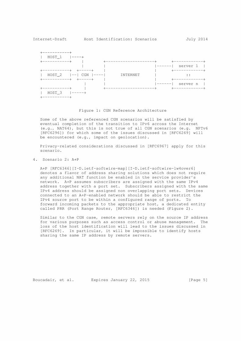
As discussed in [RFC6967], remote servers are not able to distinguish between hosts sharing the same IP address (Figure 1). As a reminder, remote servers rely on the source IP address for various purposes such as access control or abuse management. The loss of the host identification will lead to issues discussed in [RFC6269].
Boucadair, et al. Expires January 22, 2015 [Page 4]
Internet-Draft Host Identification: Scenarios July 2014
+-----------+ | HOST_1 |----+ +-----------+ | +--------------------+ +------------+ | | |------| server 1 | +-----------+ +-----+ | | +------------+ | HOST_2 |--| CGN |----| INTERNET | :: +-----------+ +-----+ | | +------------+ | | |------| server n | +-----------+ | +--------------------+ +------------+ | HOST_3 |-----+ +-----------+
Figure 1: CGN Reference Architecture
Some of the above referenced CGN scenarios will be satisfied by eventual completion of the transition to IPv6 across the Internet (e.g., NAT64), but this is not true of all CGN scenarios (e.g. NPTv6 [RFC6296]) for which some of the issues discussed in [RFC6269] will be encountered (e.g., impact on geolocation).
Privacy-related considerations discussed in [RFC6967] apply for this scenario.
4. Scenario 2: A+P
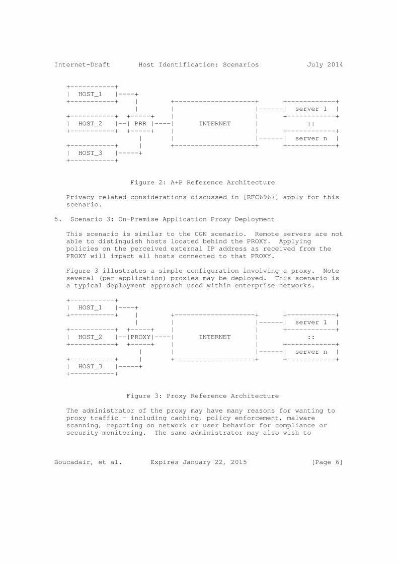
A+P [RFC6346][I-D.ietf-softwire-map][I-D.ietf-softwire-lw4over6] denotes a flavor of address sharing solutions which does not require any additional NAT function be enabled in the service provider’s network. A+P assumes subscribers are assigned with the same IPv4 address together with a port set. Subscribers assigned with the same IPv4 address should be assigned non overlapping port sets. Devices connected to an A+P-enabled network should be able to restrict the IPv4 source port to be within a configured range of ports. To forward incoming packets to the appropriate host, a dedicated entity called PRR (Port Range Router, [RFC6346]) is needed (Figure 2).
Similar to the CGN case, remote servers rely on the source IP address for various purposes such as access control or abuse management. The loss of the host identification will lead to the issues discussed in [RFC6269]. In particular, it will be impossible to identify hosts sharing the same IP address by remote servers.
Boucadair, et al. Expires January 22, 2015 [Page 5]
Internet-Draft Host Identification: Scenarios July 2014
+-----------+ | HOST_1 |----+ +-----------+ | +--------------------+ +------------+ | | |------| server 1 | +-----------+ +-----+ | | +------------+ | HOST_2 |--| PRR |----| INTERNET | :: +-----------+ +-----+ | | +------------+ | | |------| server n | +-----------+ | +--------------------+ +------------+ | HOST_3 |-----+ +-----------+
Figure 2: A+P Reference Architecture
Privacy-related considerations discussed in [RFC6967] apply for this scenario.
5. Scenario 3: On-Premise Application Proxy Deployment
This scenario is similar to the CGN scenario. Remote servers are not able to distinguish hosts located behind the PROXY. Applying policies on the perceived external IP address as received from the PROXY will impact all hosts connected to that PROXY.
Figure 3 illustrates a simple configuration involving a proxy. Note several (per-application) proxies may be deployed. This scenario is a typical deployment approach used within enterprise networks.
+-----------+ | HOST_1 |----+ +-----------+ | +--------------------+ +------------+ | | |------| server 1 | +-----------+ +-----+ | | +------------+ | HOST_2 |--|PROXY|----| INTERNET | :: +-----------+ +-----+ | | +------------+ | | |------| server n | +-----------+ | +--------------------+ +------------+ | HOST_3 |-----+ +-----------+
Figure 3: Proxy Reference Architecture
The administrator of the proxy may have many reasons for wanting to proxy traffic - including caching, policy enforcement, malware scanning, reporting on network or user behavior for compliance or security monitoring. The same administrator may also wish to
Boucadair, et al. Expires January 22, 2015 [Page 6]

Internet-Draft Host Identification: Scenarios July 2014
selectively hide or expose the internal host (or user) identity to servers. He/she may wish to hide the identity to protect end-user privacy or to reduce the ability of a rogue agent to learn the internal structure of the network. He/she may wish to allow upstream servers to identify hosts (and/or users) to enforce access policies (for example on documents or online databases), to enable account identification (on subscription-based services) or to prevent spurious misidentification of high traffic patterns as a DoS attack. Application-specific protocols exist for enabling such forwarding on some plain-text protocols (e.g., Forwarded headers on HTTP [RFC7239] or time-stamp-line headers in SMTP [RFC5321]).
Servers not receiving such notifications but wishing to perform host or user-specific processing are obliged to use other application- specific means of identification (e.g. Cookies [RFC6265]).
Packets/connections must be received by the proxy regardless of the IP address family in use. The requirements of this scenario are not satisfied by eventual completion of the transition to IPv6 across the Internet. Complications will arise for both IPv4 and IPv6.
Privacy-related considerations discussed in [RFC6967] apply for this scenario.
6. Scenario 4: Distributed Proxy Deployment
This scenario is similar to the proxy deployment scenario (Section 5) with the same use-cases. However, in this instance part of the functionality of the application proxy is located in a remote site. This may be desirable to reduce infrastructure and administration costs or because the hosts in question are mobile or roaming hosts tied to a particular administrative zone of control but not to a particular network.
In some cases, a distributed proxy is required to identify an account holder on whose behalf it is performing the caching, filtering or other desired service - for example to know which policies to enforce. Typically, IP addresses are used as a surrogate. However, in the presence of CGN, this identification becomes difficult. Alternative solutions include the use of cookies, which only work for HTTP traffic, tunnels or proprietary extensions to existing protocols.
Boucadair, et al. Expires January 22, 2015 [Page 7]

Internet-Draft Host Identification: Scenarios July 2014
+-----------+ +----------+ | HOST_1 |-------------| | +-----------+ | | +-------+ +------------+ | | | |-----| server 1 | +-----------+ | | | | +------------+ | HOST_2 |----+ | INTERNET |---| Proxy | :: +-----------+ +-----+ | | | | +------------+ |Proxy|----| | | |-----| server n | +-----------+ +-----+ | | +-------+ +------------+ | HOST_3 |----+ +----------+ +-----------+
Figure 4: Distributed Proxy Reference Architecture (1)
+-----------+ +---+ +---+ +----------+ | Host 1 +---------+ I | | I +--+ Server 1 | +-----------+ | n | +---+ | n | +----------+ | t | | P | | t | +-----------+ +---+ | e | | r | | e | +----------+ | Host 2 +--+ P | | r +--+ o +--+ r +--+ Server 2 | +-----------+ | r | | n | | x | | n | +----------+ | o |--+ e | | y | | e | :: +-----------+ | x | | t | +---+ | t | +----------+ | Host 3 +--+ y | | | | +--+ Server N | +-----------+ +---+ +---+ +---+ +----------+
Figure 5: Distributed Proxy Reference Architecture (2)
Packets/connections must be received by the proxy regardless of the IP address family in use. The requirements of this scenario are not satisfied by eventual completion of the transition to IPv6 across the Internet. Complications will arise for both IPv4 and IPv6.
If the proxy and the servers are under the responsibility of the same administrative entity (Figure 4), no privacy concerns are raised. Nevertheless, privacy-related considerations discussed in [RFC6967] apply if the proxy and the servers are not managed by the same administrative entity (Figure 5).
7. Scenario 5: Overlay Network
An overlay network is a network of machines distributed throughout multiple autonomous systems within the public Internet that can be used to improve the performance of data transport (see Figure 6). IP packets from the sender are delivered first to one of the machines that make up the overlay network. That machine then relays the IP
Boucadair, et al. Expires January 22, 2015 [Page 8]

Internet-Draft Host Identification: Scenarios July 2014
packets to the receiver via one or more machines in the overlay network, applying various performance enhancement methods.
+------------------------------------+ | | | INTERNET | | | +-----------+ | +------------+ | | HOST_1 |-----| OVRLY_IN_1 |-----------+ | +-----------+ | +------------+ | | | | | +-----------+ | +------------+ +-----------+ | +--------+ | HOST_2 |-----| OVRLY_IN_2 |-----| OVRLY_OUT |-----| SERVER | +-----------+ | +------------+ +-----------+ | +--------+ | | | +-----------+ | +------------+ | | | HOST_3 |-----| OVRLY_IN_3 |-----------+ | +-----------+ | +------------+ | | | +------------------------------------+
Figure 6: Overlay Network Reference Architecture
Such overlay networks are used to improve the performance of content delivery [IEEE1344002]. Overlay networks are also used for peer-to- peer data transport [RFC5694], and they have been suggested for use in both improved scalability for the Internet routing infrastructure [RFC6179] and provisioning of security services (intrusion detection, anti-virus software, etc.) over the public Internet [IEEE101109].
In order for an overlay network to intercept packets and/or connections transparently via base Internet connectivity infrastructure, the overlay ingress and egress hosts (OVERLAY_IN and OVERLAY_OUT) must be reliably in-path in both directions between the connection-initiating HOST and the SERVER. When this is not the case, packets may be routed around the overlay and sent directly to the receiving host.
For public overlay networks, where the ingress and/or egress hosts are on the public Internet, packet interception commonly uses network address translation for the source (SNAT) or destination (DNAT) addresses in such a way that the public IP addresses of the true endpoint hosts involved in the data transport are invisible to each other (see Figure 7). For example, the actual sender and receiver may use two completely different pairs of source and destination addresses to identify the connection on the sending and receiving networks in cases where both the ingress and egress hosts are on the public Internet.
Boucadair, et al. Expires January 22, 2015 [Page 9]

Internet-Draft Host Identification: Scenarios July 2014
ip hdr contains: ip hdr contains: SENDER -> src = sender --> OVERLAY --> src = overlay2 --> RECEIVER dst = overlay1 dst = receiver
Figure 7: NAT operations in an Overlay Network
In this scenario, the remote server is not able to distinguish among hosts using the overlay for transport. In addition, the remote server is not able to determine the overlay ingress point being used by the host, which can be useful for diagnosing host connectivity issues.
In some of the above referenced scenarios, IP packets traverse the overlay network fundamentally unchanged, with the overlay network functioning much like a CGN (Section 3). In other cases, connection- oriented data flows (e.g. TCP) are terminated by the overlay in order to perform object caching and other such transport and application layer optimizations, similar to the proxy scenario (Section 5). In both cases, address sharing is a requirement for packet/connection interception, which means that the requirements for this scenario are not satisfied by the eventual completion of the transition to IPv6 across the Internet.
More details about this scenario are provided in [I-D.williams-overlaypath-ip-tcp-rfc].
This scenario does not introduce privacy concerns since the identification of the host is local to a single administrative domain (i.e., CDN overlay Network) or passed to a remote server to help forwarding back the response to the appropriate host.
8. Scenario 6: Policy and Charging Control Architecture
This issue is related to the framework defined in [TS23.203] when a NAT is located between the PCEF (Policy and Charging Enforcement Function) and the AF (Application Function) as shown in Figure 8.
The main issue is: PCEF, PCRF and AF all receive information bound to the same UE( User Equipment) but without being able to correlate between the piece of data visible for each entity. Concretely,
o PCEF is aware of the IMSI (International Mobile Subscriber Identity) and an internal IP address assigned to the UE.
o AF receives an external IP address and port as assigned by the NAT function.
Boucadair, et al. Expires January 22, 2015 [Page 10]

Internet-Draft Host Identification: Scenarios July 2014
o PCRF is not able to correlate between the external IP address/port assigned by the NAT (received from the AF) and the internal IP address and IMSI of the UE (received from the PCEF).
+------+ | PCRF |-----------------+ +------+ | | | +----+ +------+ +-----+ +-----+ | UE |------| PCEF |---| NAT |----| AF | +----+ +------+ +-----+ +-----+
Figure 8: NAT located between AF and PCEF
This scenario can be generalized as follows (Figure 9):
o Policy Enforcement Point (PEP, [RFC2753])
o Policy Decision Point (PDP, [RFC2753])
+------+ | PDP |-----------------+ +------+ | | | +----+ +------+ +-----+ +------+ | UE |------| PEP |---| NAT |----|Server| +----+ +------+ +-----+ +------+
Figure 9: NAT located between PEP and Server
Note that an issue is encountered to enforce per-UE policies when the NAT is located before the PEP function (see Figure 10):
+------+ | PDP |------+ +------+ | | | +----+ +------+ +-----+ +------+ | UE |------| NAT |---| PEP |----|Server| +----+ +------+ +-----+ +------+
Figure 10: NAT located before PEP
This scenario does not introduce privacy concerns since the identification of the host is local to a single administrative domain and is meant to help identifying which policy to select for a UE.
Boucadair, et al. Expires January 22, 2015 [Page 11]

Internet-Draft Host Identification: Scenarios July 2014
9. Scenario 7: Emergency Calls
Voice service providers (VSPs) operating under certain jurisdictions are required to route emergency calls from their subscribers and have to include information about the caller’s location in signaling messages they send towards PSAPs (Public Safety Answering Points, [RFC6443]), via an Emergency Service Routing Proxy (ESRP, [RFC6443]). This information is used both for the determination of the correct PSAP and to reveal the caller’s location to the selected PSAP.
In many countries, regulation bodies require that this information be provided by the network rather than the user equipment, in which case the VSP needs to retrieve this information (by reference or by value) from the access network where the caller is attached.
This requires the VSP call server receiving an emergency call request to identify the relevant access network and to query a Location Information Server (LIS) in this network using a suitable look-up key. In the simplest case, the source IP address of the IP packet carrying the call request is used both for identifying the access network (thanks to a reverse DNS query) and as a look-up key to query the LIS. Obviously the user-id as known by the VSP (e.g., telephone number, or email-formatted URI) can’t be used as it is not known by the access network.
The above mechanism is broken when there is a NAT between the user and the VSP and/or if the emergency call is established over a VPN tunnel (e.g., an employee remotely connected to a company VoIP server through a tunnel wishes to make an emergency call). In such cases, the source IP address received by the VSP call server will identity the NAT or the address assigned to the caller equipment by the VSP (i.e., the address inside the tunnel). This is similar to the CGN case (Section 3) and overlay network case (Section 7) and applies irrespective of the IP versions used on both sides of the NAT and/or inside and outside the tunnel.
Therefore, the VSP needs to receive an additional piece of information that can be used to both identify the access network where the caller is attached and query the LIS for his/her location. This would require the NAT or the Tunnel Endpoint to insert this extra information in the call requests delivered to the VSP call servers. For example, this extra information could be a combination of the local IP address assigned by the access network to the caller’s equipment with some form of identification of this access network.
However, because it shall be possible to setup an emergency call regardless of the actual call control protocol used between the user
Boucadair, et al. Expires January 22, 2015 [Page 12]
Internet-Draft Host Identification: Scenarios July 2014
and the VSP (e.g., SIP [RFC3261], IAX [RFC5456], tunneled over HTTP, or proprietary protocol, possibly encrypted), this extra information has to be conveyed outside the call request, in the header of lower layers protocols.
Privacy-related considerations discussed in [RFC6967] apply for this scenario.
10. Other Deployment Scenarios
10.1. Scenario 8: Open WLAN or Provider WLAN
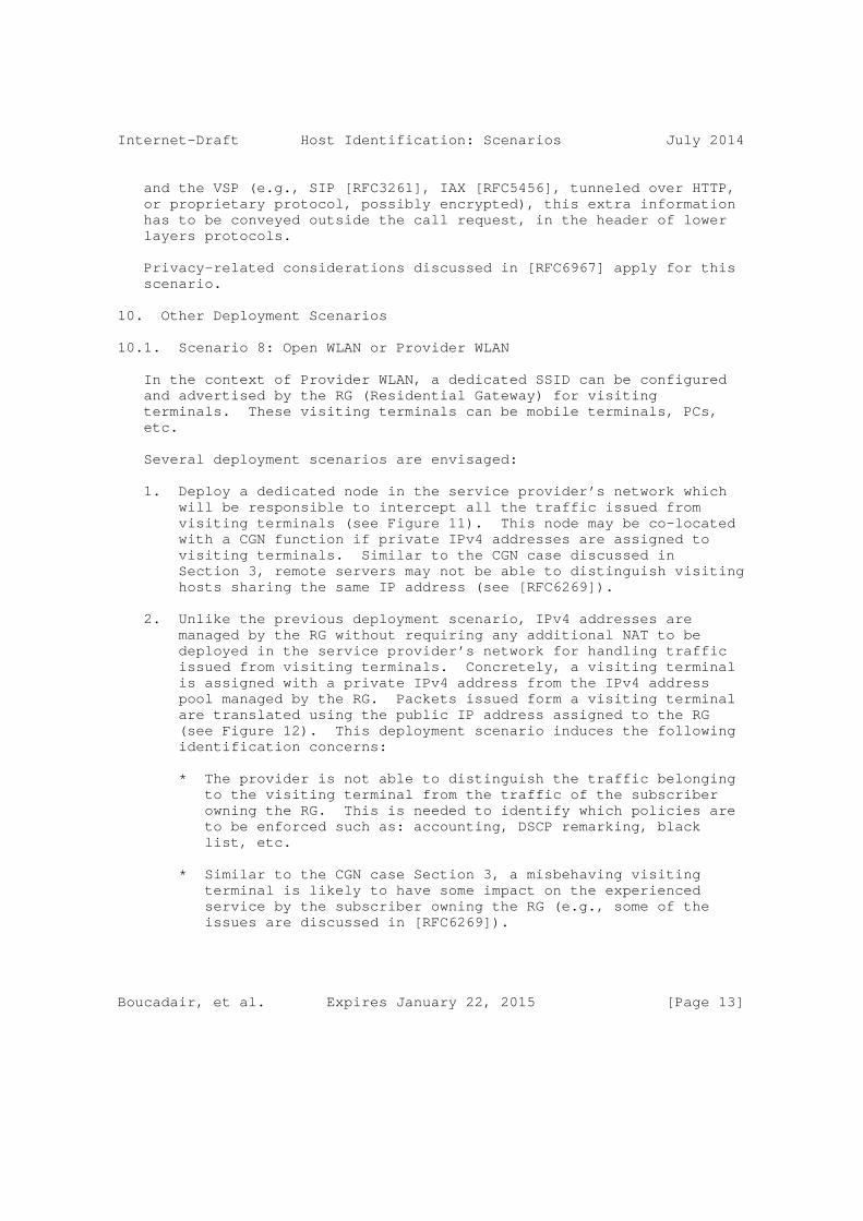
In the context of Provider WLAN, a dedicated SSID can be configured and advertised by the RG (Residential Gateway) for visiting terminals. These visiting terminals can be mobile terminals, PCs, etc.
Several deployment scenarios are envisaged:
1. Deploy a dedicated node in the service provider’s network which will be responsible to intercept all the traffic issued from visiting terminals (see Figure 11). This node may be co-located with a CGN function if private IPv4 addresses are assigned to visiting terminals. Similar to the CGN case discussed in Section 3, remote servers may not be able to distinguish visiting hosts sharing the same IP address (see [RFC6269]).
2. Unlike the previous deployment scenario, IPv4 addresses are managed by the RG without requiring any additional NAT to be deployed in the service provider’s network for handling traffic issued from visiting terminals. Concretely, a visiting terminal is assigned with a private IPv4 address from the IPv4 address pool managed by the RG. Packets issued form a visiting terminal are translated using the public IP address assigned to the RG (see Figure 12). This deployment scenario induces the following identification concerns:
* The provider is not able to distinguish the traffic belonging to the visiting terminal from the traffic of the subscriber owning the RG. This is needed to identify which policies are to be enforced such as: accounting, DSCP remarking, black list, etc.
* Similar to the CGN case Section 3, a misbehaving visiting terminal is likely to have some impact on the experienced service by the subscriber owning the RG (e.g., some of the issues are discussed in [RFC6269]).
Boucadair, et al. Expires January 22, 2015 [Page 13]

Internet-Draft Host Identification: Scenarios July 2014
+-------------+ |Local_HOST_1 |----+ +-------------+ | | | +-------------+ +-----+ | +-----------+ |Local_HOST_2 |--| RG |-|--|Border Node| +-------------+ +-----+ | +----NAT----+ | | +-------------+ | | Service Provider |Visiting Host|-----+ +-------------+
Figure 11: NAT enforced in a Service Provider’s Node
+-------------+ |Local_HOST_1 |----+ +-------------+ | | | +-------------+ +-----+ | +-----------+ |Local_HOST_2 |--| RG |-|--|Border Node| +-------------+ +-NAT-+ | +-----------+ | | +-------------+ | | Service Provider |Visiting Host|-----+ +-------------+
Figure 12: NAT located in the RG
This scenario does not introduce privacy concerns since the identification of the host is local to a single administrative domain and is meant to help identifying which policy to select for a visiting UE.
10.2. Scenario 9: Cellular Networks
Cellular operators allocate private IPv4 addresses to mobile terminals and deploy NAT44 function, generally co-located with firewalls, to access to public IP services. The NAT function is located at the boundaries of the PLMN (Public Land Mobile Network). IPv6-only strategy, consisting in allocating IPv6 prefixes only to mobile terminals, is considered by various operators. A NAT64 function is also considered in order to preserve IPv4 service continuity for these customers.
These NAT44 and NAT64 functions bring some issues very similar to those mentioned in Figure 1 and Section 8. This issue is
Boucadair, et al. Expires January 22, 2015 [Page 14]

Internet-Draft Host Identification: Scenarios July 2014
particularly encountered if policies are to be applied on the Gi interface: a private IP address is assigned to the mobile terminals, there is no correlation between the internal IP address and the external address:port assigned by the NAT function, etc.
Privacy-related considerations discussed in [RFC6967] apply for this scenario.
10.3. Scenario 10: Femtocells
This scenario can be seen as a combination of the scenarios described in Section 10.1 and Section 8.
The reference architecture is shown in Figure 8.
+---------------------------+ | +----+ +--------+ +----+ | +-----------+ +-------------------+ | | UE | | Stand- |<=|====|=|===|===========|==|=>+--+ +--+ | | +----+ | alone | | RG | | | | | | | | | Mobile | | | FAP | +----+ | | | | |S | |F | Network| | +--------+ (NAPT) | | Broadband | | |e | |A | | +---------------------------+ | Fixed | | |G |-|P | +-----+| | Network | | |W | |G |-| Core|| +---------------------------+ | (BBF) | | | | |W | | Ntwk|| | +----+ +------------+ | | | | | | | | +-----+| | | UE | | Integrated |<====|===|===========|==|=>+--+ +--+ | | +----+ | FAP (NAPT) | | +-----------+ +-------------------+ | +------------+ | +---------------------------+
<=====> IPsec tunnel CoreNtwk Core Network FAPGW FAP Gateway SeGW Security Gateway
Figure 13: Femtocell Reference Architecture
UE is connected to the FAP at the residential gateway (RG), routed back to 3GPP Evolved Packet Core (EPC). UE is assigned IPv4 address by the Mobile Network. Mobile operator’s FAP leverages the IPsec IKEv2 to interconnect FAP with the SeGW over the BBF network. Both the FAP and the SeGW are managed by the mobile operator which may be a different operator for the BBF network.
An investigated scenario is the mobile operator to pass on its mobile subscriber’s policies to the BBF to support traffic policy control . But most of today’s broadband fixed networks are relying on the private IPv4 addressing plan (+NAPT) to support its attached devices
Boucadair, et al. Expires January 22, 2015 [Page 15]

Internet-Draft Host Identification: Scenarios July 2014
including the mobile operator’s FAP. In this scenario, the mobile network needs to:
o determine the FAP’s public IPv4 address to identify the location of the FAP to ensure its legitimacy to operate on the license spectrum for a given mobile operator prior to the FAP be ready to serve its mobile devices.
o determine the FAP’s pubic IPv4 address together with the translated port number of the UDP header of the encapsulated IPsec tunnel for identifying the UE’s traffic at the fixed broadband network.
o determine the corresponding FAP’s public IPv4 address associated with the UE’s inner-IPv4 address which is assigned by the mobile network to identify the mobile UE to allow the PCRF to retrieve the special UE’s policy (e.g., QoS) to be passed onto the Broadband Policy Control Function (BPCF) at the BBF network.
SeGW would have the complete knowledge of such mapping, but the reasons for unable to use SeGW for this purpose is explained in "Problem Statements" (section 2 of [I-D.so-ipsecme-ikev2-cpext]).
This scenario involves PCRF/BPCF but it is valid in other deployment scenarios making use of AAA servers.
The issue of correlating the internal IP address and the public IP address is valid even if there is no NAT in the path.
This scenario does not introduce privacy concerns since the identification of the host is local to a single administrative domain and is meant to help identifying which policy to select for a UE.
10.4. Scenario 11: Traffic Detection Function
Operators expect that the traffic subject to the packet inspection is routed via the Traffic Detection Function (TDF) function as requirement specified in [TS29.212], otherwise, the traffic may bypass the TDF. This assumption only holds if it is possible to identify individual UEs behind NA(P)T which may be deployed into the RG in fixed broadband network, shown in Figure 14. As a result, additional mechanisms are needed to enable this requirement.
Boucadair, et al. Expires January 22, 2015 [Page 16]

Internet-Draft Host Identification: Scenarios July 2014
+--------+ | | +-------+ PCRF | | | | | +--------+ +--------+ +--------+ +--------+ +----+----+ | | | | | +-----+ | | ------------------------------------------------------------------ | | | | | | | TDF | / \ | ****************************************************************** | | | +-------+ | | | Service | | | | | | | \ / | | | | | | | +--------+ | | | | | | +--------+ PDN | | ********---------**********--------************------------******* | | UE | | RG | | BNG +------------------+ Gateway| +--------+ +--------+ +--------+ +--------+
Legends: --------- 3GPP UE User Plane Traffic Offloaded subject to packet inspection ********* 3GPP UE User Plane Traffic Offloaded not subject to packet inspection *****---- 3GPP UE User Plane Traffic Home Routed
Figure 14: UE’s Traffic Routed with TDF
This scenario does not introduce privacy concerns since the identification of the host is local to a single administrative domain and is meant to help identifying which policy to select for a UE.
10.5. Scenario 12: Fixed and Mobile Network Convergence
In the Policy for Convergence of Fixed Mobile Convergence (FMC) scenario, the fixed broadband network must partner with the mobile network to acquire the policies for the terminals or hosts attaching to the fixed broadband network, shown in Figure 15 so that host- specific QoS and accounting policies can be applied.
A UE is connected to the RG, routed back to the mobile network. The mobile operator’s PCRF needs to maintain the interconnect with the Broadband Policy Control Function (BPCF) in the BBF network for PCC (Section 8). The hosts (i.e., UEs) attaching to fixed broadband network with a NA(P)T deployed should be identified. Based on the UE identification, the BPCF to deploy policy rules in the fixed broadband network can acquire the associated policy rules of the identified UE from the PCRF in the mobile network. But in the fixed
Boucadair, et al. Expires January 22, 2015 [Page 17]

Internet-Draft Host Identification: Scenarios July 2014
broadband network, private IPv4 address is supported. The similar requirements are raised in this scenario as Section 10.3.
+------------------------------+ +-------------+ | | | | | +------+ | | +------+ | | | BPCF +---+---+-+ PCRF | | | +--+---+ | | +---+--+ | +-------+ | | | | | | |HOST_1 |Private IP1 +--+---+ | | +---+--+ | +-------+ | +----+ | | | | | | | | | RG | | | | | | | | | |with+-------------+ BNG +--------+ PGW | | +-------+ | | NAT| | | | | | | | |HOST_2 | | +----+ | | | | | | | +-------+Private IP2 +------+ | | +------+ | | | | | | | | | | Fixed | | Mobile | | Broadband | | Network | | Network | | | | | | | +------------------------------+ +-------------+
Figure 15: Reference Architecture for Policy for Convergence in Fixed and Mobile Network Convergence (1)
In IPv6 network, the similar issues exists when the IPv6 prefix is sharing between multiple UEs attaching to the RG (see Figure 16). The case applies when RG is assigned a single prefix, the home network prefix, e.g. using DHCPv6 Prefix Delegation [RFC3633] with the edge router, BNG acting as the Delegating Router (DR). RG uses the home network prefix in the address configuration using stateful (DHCPv6) or stateless address assignment (SLAAC) techniques.
Boucadair, et al. Expires January 22, 2015 [Page 18]

Internet-Draft Host Identification: Scenarios July 2014
+------------------------------+ +-------------+ | | | | | | | +------+ | | +-------------+ PCRF | | | | | | +---+--+ | +-------+ | | | | | | |HOST_1 |--+ +--+---+ | | +---+--+ | +-------+ | +----+ | | | | | | | | | RG | | | | | | | | | | +------------+ BNG +---------+ PGW | | +-------+ | | | | | | | | | | |HOST_2 |--+ +----+ | | | | | | | +-------+ | +------+ | | +------+ | | | | | | | | | | Fixed | | Mobile | | Broadband | | Network | | Network | | | | | | | +------------------------------+ +-------------+
Figure 16: Reference Architecture for Policy for Convergence in Fixed and Mobile Network Convergence (2)
BNG acting as PCEF initiates an IP Connectivity Access Network (IP- CAN) session with the policy server, a.k.a. Policy and Charging Rules Function (PCRF), to receive the Quality of Service (QoS) parameters and Charging rules. BNG provides to the PCRF the IPv6 Prefix assigned to the host, in this case the home network prefix and an ID which in this case has to be equal to the RG specific home network line ID.
HOST_1 in Figure 16 creates an 128-bit IPv6 address using this prefix and adding its interface id. Having completed the address configuration, the host can start communication with a remote hosts over Internet. However, no specific IP-CAN session can be assigned to HOST_1, and consequently the QoS and accounting performed will be based on RG subscription.
Another host, e.g. HOST_2, attaches to RG and also establishes an IPv6 address using the home network prefix. Edge router, the BNG, is not involved with this and all other such address assignments.
This leads to the case where no specific IP-CAN session/sub-session can be assigned to the hosts, HOST_1, HOST_2, etc., and consequently the QoS and accounting performed can only be based on RG subscription and not host specific. Therefore IPv6 prefix sharing in Policy for
Boucadair, et al. Expires January 22, 2015 [Page 19]

Internet-Draft Host Identification: Scenarios July 2014
Convergence scenario leads to similar issues as the address sharing as it has been explained in the previous scenarios in this document.
11. Synthesis
The following table shows whether each scenario is valid for IPv4/ IPv6 and if it is within one single administrative domain or span multiple domains.
+-------------------+------+-------------+-----------------------+ | scenario | IPv4 | IPv6 | Single Administrative | | | |------+------| Domain | | | |Client|Server| | +-------------------+------+------+------+-----------------------+ | CGN | Yes |Yes(1)| No | No | | A+P | Yes | No | No | No | | Application Proxy | Yes | Yes | Yes | No | | Distributed Proxy | Yes | Yes | Yes | Yes/No | | Overlay Networks | Yes |Yes(3)|Yes(3)| No | | PCC | Yes |Yes(1)| No | Yes | | Emergency Calls | Yes | Yes |Yes | No | | Provider WLAN | Yes | No | No | Yes | | Cellular Networks | Yes |Yes(1)| No | Yes | | Femtocells | Yes | No | No | No | | TDF | Yes | Yes | No | Yes | | FMC | Yes |Yes(1)| No | No | +-------------------+------+------+------------------------------+
Notes: (1) e.g., NAT64 (2) A proxy can use IPv6 for the communication leg with the server or the application client. (3) This scenario is a combination of CGN and Application Proxies.
12. Privacy Considerations
Privacy-related considerations that apply to means to reveal a host identifiers are discussed in [RFC6967]. This document does not introduce additional privacy issues than those discussed in [RFC6967].
13. Security Considerations
This document does not define an architecture nor a protocol; as such it does not raise any security concern. Host identifier related security considerations are discussed in [RFC6967].
Boucadair, et al. Expires January 22, 2015 [Page 20]

Internet-Draft Host Identification: Scenarios July 2014
14. IANA Considerations
This document does not require any action from IANA.
15. Acknowledgments
Many thanks to F. Klamm, D. Wing, and D. von Hugo for their review.
J. Touch, S. Farrel, and S. Moonesamy provided useful comments in the intarea mailing list.
Figure 8 and part of the text in Section 10.3 are inspired from [I-D.so-ipsecme-ikev2-cpext].
16. Informative References
[EFFOpenWireless] EFF, , "Open Wireless, https://www.eff.org/issues/open- wireless", 2014.
[I-D.ietf-softwire-lw4over6] Cui, Y., Qiong, Q., Boucadair, M., Tsou, T., Lee, Y., and I. Farrer, "Lightweight 4over6: An Extension to the DS- Lite Architecture", draft-ietf-softwire-lw4over6-10 (work in progress), June 2014.
[I-D.ietf-softwire-map] Troan, O., Dec, W., Li, X., Bao, C., Matsushima, S., Murakami, T., and T. Taylor, "Mapping of Address and Port with Encapsulation (MAP)", draft-ietf-softwire-map-10 (work in progress), January 2014.
[I-D.so-ipsecme-ikev2-cpext] So, T., "IKEv2 Configuration Payload Extension for Private IPv4 Support for Fixed Mobile Convergence", draft-so- ipsecme-ikev2-cpext-02 (work in progress), June 2012.
[I-D.tsou-stateless-nat44] Tsou, T., Liu, W., Perreault, S., Penno, R., and M. Chen, "Stateless IPv4 Network Address Translation", draft-tsou- stateless-nat44-02 (work in progress), October 2012.
[I-D.williams-overlaypath-ip-tcp-rfc] Williams, B., "Overlay Path Option for IP and TCP", draft- williams-overlaypath-ip-tcp-rfc-04 (work in progress), June 2013.
Boucadair, et al. Expires January 22, 2015 [Page 21]

Internet-Draft Host Identification: Scenarios July 2014
[IEEE101109] Salah, K., Calero, J., Zeadally, S., Almulla, S., and M. ZAaabi, "Using Cloud Computing to Implement a Security Overlay Network, IEEE Security & Privacy, 21 June 2012. IEEE Computer Society Digital Library.", June 2012.
[IEEE1344002] Byers, J., Considine, J., Mitzenmacher, M., and S. Rost, "Informed content delivery across adaptive overlay networks: IEEE/ACM Transactions on Networking, Vol 12, Issue 5, ppg 767-780", October 2004.
[RFC2753] Yavatkar, R., Pendarakis, D., and R. Guerin, "A Framework for Policy-based Admission Control", RFC 2753, January 2000.
[RFC3261] Rosenberg, J., Schulzrinne, H., Camarillo, G., Johnston, A., Peterson, J., Sparks, R., Handley, M., and E. Schooler, "SIP: Session Initiation Protocol", RFC 3261, June 2002.
[RFC3633] Troan, O. and R. Droms, "IPv6 Prefix Options for Dynamic Host Configuration Protocol (DHCP) version 6", RFC 3633, December 2003.
[RFC5321] Klensin, J., "Simple Mail Transfer Protocol", RFC 5321, October 2008.
[RFC5456] Spencer, M., Capouch, B., Guy, E., Miller, F., and K. Shumard, "IAX: Inter-Asterisk eXchange Version 2", RFC 5456, February 2010.
[RFC5694] Camarillo, G. and IAB, "Peer-to-Peer (P2P) Architecture: Definition, Taxonomies, Examples, and Applicability", RFC 5694, November 2009.
[RFC6146] Bagnulo, M., Matthews, P., and I. van Beijnum, "Stateful NAT64: Network Address and Protocol Translation from IPv6 Clients to IPv4 Servers", RFC 6146, April 2011.
[RFC6179] Templin, F., "The Internet Routing Overlay Network (IRON)", RFC 6179, March 2011.
[RFC6265] Barth, A., "HTTP State Management Mechanism", RFC 6265, April 2011.
Boucadair, et al. Expires January 22, 2015 [Page 22]

Internet-Draft Host Identification: Scenarios July 2014
[RFC6269] Ford, M., Boucadair, M., Durand, A., Levis, P., and P. Roberts, "Issues with IP Address Sharing", RFC 6269, June 2011.
[RFC6296] Wasserman, M. and F. Baker, "IPv6-to-IPv6 Network Prefix Translation", RFC 6296, June 2011.
[RFC6333] Durand, A., Droms, R., Woodyatt, J., and Y. Lee, "Dual- Stack Lite Broadband Deployments Following IPv4 Exhaustion", RFC 6333, August 2011.
[RFC6346] Bush, R., "The Address plus Port (A+P) Approach to the IPv4 Address Shortage", RFC 6346, August 2011.
[RFC6443] Rosen, B., Schulzrinne, H., Polk, J., and A. Newton, "Framework for Emergency Calling Using Internet Multimedia", RFC 6443, December 2011.
[RFC6888] Perreault, S., Yamagata, I., Miyakawa, S., Nakagawa, A., and H. Ashida, "Common Requirements for Carrier-Grade NATs (CGNs)", BCP 127, RFC 6888, April 2013.
[RFC6967] Boucadair, M., Touch, J., Levis, P., and R. Penno, "Analysis of Potential Solutions for Revealing a Host Identifier (HOST_ID) in Shared Address Deployments", RFC 6967, June 2013.
[RFC7239] Petersson, A. and M. Nilsson, "Forwarded HTTP Extension", RFC 7239, June 2014.
[TS23.203] 3GPP, , "Policy and charging control architecture", September 2012.
[TS29.212] 3GPP, , "Policy and Charging Control (PCC); Reference Points", December 2013.
Authors’ Addresses
Mohamed Boucadair (editor) France Telecom Rennes 35000 France
Email: [email protected]
Boucadair, et al. Expires January 22, 2015 [Page 23]

Internet-Draft Host Identification: Scenarios July 2014
David Binet France Telecom Rennes France
Email: [email protected]
Sophie Durel France Telecom Rennes France
Email: [email protected]
Bruno Chatras France Telecom Paris France
Email: [email protected]
Tirumaleswar Reddy Cisco Systems Cessna Business Park, Varthur Hobli Sarjapur Marathalli Outer Ring Road Bangalore, Karnataka 560103 India
Email: [email protected]
Brandon Williams Akamai, Inc. Cambridge MA USA
Email: [email protected]
Boucadair, et al. Expires January 22, 2015 [Page 24]

Internet-Draft Host Identification: Scenarios July 2014
Behcet Sarikaya Huawei 5340 Legacy Dr. Building 3, Plano, TX 75024 USA
Email: [email protected]
Li Xue Huawei Beijing China
Email: [email protected]
Richard Stewart Wheeldon Cisco Systems Qube, 90 Whitfield Street London W1T 4EZ UK
Email: [email protected]
Boucadair, et al. Expires January 22, 2015 [Page 25]

Network Working Group Y. DesmouceauxInternet-Draft Cisco SystemsIntended status: Informational July 2014Expires: December 31, 2014
Power consumption due to IPv6 multicast on WiFi devices draft-desmouceaux-ipv6-mcast-wifi-power-usage-00
Abstract
IPv6 networks make a consequent use of multicast for several purposes, including mandatory functions such as Neighbor Discovery. Although this use of multicast does not create real difficulties on wired networks, it can become painful on wireless ones, notably in terms of power consumption. There might be little effect on home networks, however, such effects become more important on large-scale networks. This memo provides statistics about the multicast traffic rate in a large IPv6 wireless network and the induced device power consumption, in response to a call emitted at IETF 89.
Status of this Memo
This Internet-Draft is submitted in full conformance with the provisions of BCP 78 and BCP 79.
Internet-Drafts are working documents of the Internet Engineering Task Force (IETF). Note that other groups may also distribute working documents as Internet-Drafts. The list of current Internet- Drafts is at http://datatracker.ietf.org/drafts/current/.
Internet-Drafts are draft documents valid for a maximum of six months and may be updated, replaced, or obsoleted by other documents at any time. It is inappropriate to use Internet-Drafts as reference material or to cite them other than as "work in progress."
This Internet-Draft will expire on December 31, 2014.
Copyright Notice
Copyright (c) 2014 IETF Trust and the persons identified as the document authors. All rights reserved.
This document is subject to BCP 78 and the IETF Trust’s Legal Provisions Relating to IETF Documents (http://trustee.ietf.org/ license-info) in effect on the date of publication of this document. Please review these documents carefully, as they describe your rights
Desmouceaux Expires December 31, 2014 [Page 1]

Internet-Draft IPv6 multicast, WiFi power usage July 2014
and restrictions with respect to this document. Code Components extracted from this document must include Simplified BSD License text as described in Section 4.e of the Trust Legal Provisions and are provided without warranty as described in the Simplified BSD License.
Table of Contents
1. Introduction . . . . . . . . . . . . . . . . . . . . . . . . . 2 2. IPv6 typical multicast traffic . . . . . . . . . . . . . . . . 3 2.1. Behavior when joining a network . . . . . . . . . . . . . 3 2.2. Behavior once connected . . . . . . . . . . . . . . . . . 3 3. Power consumption induced by multicast traffic . . . . . . . . 4 4. Large-scale wireless networks . . . . . . . . . . . . . . . . 5 4.1. Typical orders of magnitude . . . . . . . . . . . . . . . 5 4.1.1. Arrival rates . . . . . . . . . . . . . . . . . . . . 5 4.1.2. Connection durations . . . . . . . . . . . . . . . . . 6 4.2. Influence of such networks over devices . . . . . . . . . 7 4.3. Roaming . . . . . . . . . . . . . . . . . . . . . . . . . 7 5. Possible solutions . . . . . . . . . . . . . . . . . . . . . . 8 5.1. Optimizing Router Solicitations retransmissions . . . . . 8 5.2. Proxying multicast traffic . . . . . . . . . . . . . . . . 8 6. Acknowledgements . . . . . . . . . . . . . . . . . . . . . . . 9 7. IANA Considerations . . . . . . . . . . . . . . . . . . . . . 9 8. Security Considerations . . . . . . . . . . . . . . . . . . . 9 9. References . . . . . . . . . . . . . . . . . . . . . . . . . . 9 9.1. Normative References . . . . . . . . . . . . . . . . . . . 9 9.2. Informative References . . . . . . . . . . . . . . . . . . 10 Author’s Address . . . . . . . . . . . . . . . . . . . . . . . . . 10
1. Introduction
Multicast is widely used in IPv6 for configuration purposes through the Neighbor Discovery protocol [RFC4861]. On IEEE 802.11 wireless links, this can have a negative impact on low-energy devices such as smartphones, as stated in [I-D.vyncke-6man-mcast-not-efficient]. The 802.11 protocol [IEEE80211] includes a power-save mode for such devices, allowing them to be in a sleep state in which they will be notified when packets addressed to them are pending. However, there is no known powerful equivalent of wired-links Multicast Listener Discovery (MLD) snooping [RFC4541], hence all devices will be woken up when multicast traffic is pending.
In this document, we provide data illustrating the issue at 3 levels:
o typical multicast traffic emitted by a device when joining an IPv6 network, and ’background multicast noise’ generated once connected;
o power consumption statistics for wireless devices when confronted to multicast traffic;
o orders of magnitude of connections frequencies and durations in
Desmouceaux Expires December 31, 2014 [Page 2]

Internet-Draft IPv6 multicast, WiFi power usage July 2014
large-scale wireless networks.
Confronting these 3 levels makes it possible to model the power consumption overhead of multicast traffic on typical large wireless networks.
We finally discuss possible solutions at the IP and the 802.11 level.
2. IPv6 typical multicast traffic
2.1. Behavior when joining a network
When joining an IPv6 network, devices usually emit the following multicast traffic:
1. duplicate address detection for the link-local address;
2. router solicitation;
3. duplicate address detection for the SLAAC address;
4. duplicate address detection for the SLAAC privacy address.
In addition, MLDv2 [RFC3810] frames are emitted for registration to the solicited-node multicast addresses needed for Duplicate Address Detection. Their number is not deterministic since other multicast protocols may interfere, but is typically at least 4.
Depending on the configuration of the router, the Router Advertisement sent by the router in response to the node’s Router Solicitation may also be multicast.
On Linux and Apple MacOS X clients that were tested, joining the network also induces Multicast Domain Name System (mDNS) [RFC6762] traffic. Once more, the number of packets emitted depends on the network environment, but is around 20. Likewise, Microsoft Windows clients generate Link-local Multicast Name Resolution (LLMNR) [RFC4795] multicast traffic when they connect to the network.
2.2. Behavior once connected
Once connected, some devices keep on sending IPv6 multicast frames. Protocols inducing such traffic include Neighbor Discovery, MLD, and local discovery or name-resolution protocols, such as mDNS, LLMNR, Simple Service Discovery Protocol (SSDP), Web Services Dynamic Discovery (WS-D).
On a typical middle-scale enterprise network, IPv6 multicast traffic induced by these protocols has a noticeable impact. Our measures on a 160-hosts network show that the average rate of multicast traffic transiting through the link is 4.5 frames per second. The following table shows the repartition of the multicast traffic between these
Desmouceaux Expires December 31, 2014 [Page 3]

Internet-Draft IPv6 multicast, WiFi power usage July 2014
protocols, as it was measured:
Protocol ICMPv6 mDNS LLMNR WS-D
Ratio 0.53 0.33 0.12 0.03
Based on the previous data, we can deduce how much multicast traffic is generated by a "representative" device. Doing a simple cross- multiplication, we obtain a rate of 0.028 multicast packets/s for a single device, or 101 frames/hour. (This result is confirmed on a small isolated test network of two hosts.) The following table shows the indicative number of multicast packets emitted by a such a representative device on our test network in an hour:
Protocol ICMPv6 mDNS LLMNR WS-D
Frames per hour 53 33 12 3
3. Power consumption induced by multicast traffic
While multicast traffic has no significant influence on actively connected devices, it might have a poor impact on the ones that are in power-save mode.
In power-save mode, the hardware of such a device needs to regularly wake up in order to check whether pending frames are buffered for it. To do so, it wakes up every DTIM_PERIOD beacons (DTIM_PERIOD usually being set to 1 or 2) and retrieves the beacon emitted by the Access Point (AP). If multicast traffic is pending, this will be indicated by the AP by setting a specific bit in the beacons’s Time Information Management (TIM) information element to 1.
If a device sees that this bit is set, it will stay awake in order to retrieve the frames. The device CPU will then be awakened and frames will be transmitted by the wireless firmware to the IP stack. (Note that this might not happen if the firmware implements a multicast filter, but even in this case, current will be drawn to retrieve the frames.)
Power consumption measurements on smartphone devices confirm the negative impact of multicast traffic on sleeping devices. The measurement was performed on a Samsung i9195 by attaching an ammeter between the battery and the phone. When idle (screen off, GSM off, WiFi on, 802.11 power-save enabled by the device), current drawn is 10 mA in average. When a multicast frame is received and the CPU awakened to process it, the current draw goes to between 100 and 150 mA during a small peak of time.
Desmouceaux Expires December 31, 2014 [Page 4]

Internet-Draft IPv6 multicast, WiFi power usage July 2014
Assuming that the duration of the current peak induced by processing a multicast frame is 0.1 s, a device would hence use K times more energy when it receives RATE multicast packets per second, than when it receives none, where K = (10*(1 - RATE*0.1) + 150*RATE*0.1)/10. The following table gives K as a function of RATE.
RATE (pkts/s) 0.01 0.1 0.5 1 2 4 >10
K 1.014 1.14 1.7 2.4 3.8 6.6 15
A possible workaround to this issue is to implement a multicast filter at the firmware level, which will only forward multicast packets to the IP stack if their destination address matches one of those registered by the device. Although this would have a positive impact on battery consumption, the following measurements show that this is not entirely satisfying.
Indeed, current drawn to retrieve pending multicast frames at L2 without waking up the main CPU is around 40 mA, which is still 4 times more than idle consumption. In order to simulate this, one can tweak a router so that it always advertises the presence of multicast frames by setting the TIM multicast bit to 1. The device’s radio will then always try to retrieve frames following this beacon.
4. Large-scale wireless networks
Previous sections provide data about the battery usage induced by individual multicast frames, and the number of multicast frames generated by a single host when connecting and once connected.
In order to model the battery usage of real-life networks, the following section provides data about connection arrival rates and connection durations in usual large-scale wireless networks.
4.1. Typical orders of magnitude
The following results are based on anonymized data from a dualstack WiFi network in a conference setup. These data provide interesting statistics about user habits in a network characterized by mobility, where users move much from one room to another. Plus, it is a good example of a large wireless network, since the user count during working hours is between 600 and 700.
4.1.1. Arrival rates
Arrival rates in this test network follow a probability distribution which is very close to an exponential law (the error rate being only 6%). The observed parameter for this law is such that 1/lambda = 6 seconds.
Desmouceaux Expires December 31, 2014 [Page 5]

Internet-Draft IPv6 multicast, WiFi power usage July 2014
We are therefore in a scheme expected by the classical queuing theory, where arrivals are memoryless and have the Markov property of independence of the past. The smallness of the parameter is also an indicator of the great mobility of such networks: in average, a client joined the network every 6 seconds.
There is a small bias in previous measures due to people arriving en masse at the beginning of the day and going to lunch at noon. This bias does not affect the exponential nature of the law. However, it has an non-negligible effect over the parameter of the distribution. Computing the probability distribution over a shorter unbiased amount of time leads to a greater arrival rate: 1/lambda becomes 4.5 seconds.
From these data it appears that arrival rates in wireless networks characterized by mobility are high. Since arrivals mean multicast traffic issued by the client’s IPv6 stack, this already provides a rough intuition that large wireless networks feature high rates of multicast frames.
4.1.2. Connection durations
Once clients are connected, duration of their connections follow a less typical probability distribution, which form is represented below:
dur. distr. ^ | || | || | |\ | | | | | | | | | | | \ | | \_ | | \__ | | \_____ |____| \______ | \_________ +--------------------------------------> t
From these data it appears that there is a peak of connections which last 5 minutes, whereas almost no connection lasts less than this. A plausible explanation for this is that there are two kinds of behaviors: devices which automatically join the network without human intervention and disconnect after an idle timeout, and users who consciously connect to the network. After this peak, the distribution is roughly an exponential law, which correspond to the latter case.
Desmouceaux Expires December 31, 2014 [Page 6]

Internet-Draft IPv6 multicast, WiFi power usage July 2014
An average connection time of 55 minutes has been measured: at least, clients do not seem to be eager to leave the network too soon once they have joined it.
In our test network, arrivals follow an exponential law, and service times do not follow a close-form probability distribution. We can therefore model it as an M/G/oo queue. Once stabilized, the number of hosts in such a system follows a Poisson law of parameter S/T, where S is the expected service time and T=1/lambda the expected time between two arrivals.
4.2. Influence of such networks over devices
In this section, we model the influence of a large wireless network over a device, in terms of power consumption.
Let us assume that in average, N devices are present in the network, and that the arrival rate is lambda. (See Section 4.1 for typical numerical values). Then, Section 2 implies that the rate of multicast frames in the network is RATE = 0.025*N + 4*lambda. The following table gives RATE for a few values of N and lambda:
N 5 10 50 100 500 500
1/lambda (s) 600 600 60 60 60 5
RATE (pkts/s) 0.13 0.26 1.32 2.57 12.6 13.3
Finally, using Section 3, we can compute what is the energy overhead induced by the multicast traffic on a device. This overhead is K = (10*(1 - (0.025*N + 4*lambda)*10 + 150*(0.025*N + 4*lambda)*10)/10. The following table gives K as a function of N and lambda:
N 5 10 50 100 500 500
1/lambda (s) 600 600 60 60 60 5
K 1.18 1.36 2.84 4.59 15 15
Thus, battery consumption induced by multicast traffic will be doubled in a network of 30 nodes where the arrival rate is 10 minutes.
4.3. Roaming
Depending on the configuration of the wireless network, roaming might have different consequences on multicast traffic emission.
Desmouceaux Expires December 31, 2014 [Page 7]

Internet-Draft IPv6 multicast, WiFi power usage July 2014
When a host moves from one access point to another, roaming is supposed to be seamless. If a device detects a drop in signal quality, it will probe for a nearer access point with the same SSID. If it finds one, it will send an Authentication frame and a Reassociation Request. This will seem transparent to L3, except that some timers may time out, causing retransmissions.
However, if access points are not properly geographically distributed within the network, a device might lose connection to one before it can reconnect to another. In such a case, seamless roaming cannot happen and the device will have to go through the whole process of connection at the IPv6 level. This will generate multicast traffic as discussed in Section 2.1.
5. Possible solutions
[I-D.yourtchenko-colitti-nd-reduce-multicast] already provides solutions at the IP layer. These include:
o increasing intervals between Router Advertisements, and possibly remove the limit of 9000 s set by [RFC4861];
o increasing the timer value for Neighbor Unreachability Detection;
o unicasting Router Advertisements;
o multicast filtering at the infrastructure level (MLD snooping).
At the L2 layer, it suggests using an efficient on-device multicast filter which would send frames to the IP layer only if their destination address is registered.
We explore other possible solutions in the next sections.
5.1. Optimizing Router Solicitations retransmissions
Some wireless systems retransmit all multicast packets received, so that hosts have a better chance to obtain them. This causes a problem when retransmitted packets are not desirable for hosts.
Without having to implementing a full multicast snooping mechanism, which can be costly in terms of resources and complexity for small systems like home boxes, a simple fix can be applied to APs in order to reduce the amount of multicast traffic retransmitted. APs should refrain from retransmitting packets destined to the all routers address (ff02::2), since routers should not be present on the wireless side. Essentially, Router Solicitations will be concerned.
5.2. Proxying multicast traffic
Desmouceaux Expires December 31, 2014 [Page 8]

Internet-Draft IPv6 multicast, WiFi power usage July 2014
Some multicast traffic is only relevant to routers (for instance, MLD reports) or can be proxied by them (mDNS, ND). For instance, [RFC4389] specifies a means to proxy Neighbor Discovery traffic. Hosts are informed of the router proxying Neighbor Discovery traffic thanks to a bit in Router Advertisements.
On the same model, a more general option in Router Advertisements could indicate which multicast addresses a router is able to proxy. When a host receives such a Router Advertisement, it will record those addresses. It will then use the router L2 address instead of a 33:33:XX:XX:XX:XX multicast L2 address as destination for corresponding packets, thus reducing multicast traffic emission. The router will still be able to know that the final destination is multicast, since the destination IP address remains multicast (a behavior permitted by [RFC6085]). A disadvantage of this solution, though, is that it requires changes to the hosts.
6. Acknowledgements
The author would like to thank Andrew Yourtchenko, Eric Vyncke, Ole Troan, Brian Hart and Mark Townsley for their precious opinions on the subject.
7. IANA Considerations
This memo includes no request to IANA.
8. Security Considerations
None.
9. References
9.1. Normative References
[IEEE80211] Institute of Electrical and Electronics Engineers, "Wireless LAN Medium Access Control (MAC) and Physical Layer (PHY) Specifications", IEEE Standard 802.11, 2012.
[RFC3810] Vida, R. and L. Costa, "Multicast Listener Discovery Version 2 (MLDv2) for IPv6", RFC 3810, June 2004.
[RFC4861] Narten, T., Nordmark, E., Simpson, W. and H. Soliman, "Neighbor Discovery for IP version 6 (IPv6)", RFC 4861, September 2007.
[RFC6085] Gundavelli, S., Townsley, M., Troan, O. and W. Dec, "Address Mapping of IPv6 Multicast Packets on Ethernet", RFC 6085, January 2011.
[RFC6762] Cheshire, S. and M. Krochmal, "Multicast DNS", RFC 6762, February 2013.
Desmouceaux Expires December 31, 2014 [Page 9]
Internet-Draft IPv6 multicast, WiFi power usage July 2014
9.2. Informative References
[I-D.vyncke-6man-mcast-not-efficient] Vyncke, E., Thubert, P., Levy-Abegnoli, E. and A. Yourtchenko, "Why Network-Layer Multicast is Not Always Efficient At Datalink Layer", Internet-Draft draft-vyncke- 6man-mcast-not-efficient-01, February 2014.
[I-D.yourtchenko-colitti-nd-reduce-multicast] Yourtchenko, A. and L. Colitti, "Reducing Multicast in IPv6 Neighbor Discovery", Internet-Draft draft- yourtchenko-colitti-nd-reduce-multicast-00, February 2014.
[RFC4389] Thaler, D., Talwar, M. and C. Patel, "Neighbor Discovery Proxies (ND Proxy)", RFC 4389, April 2006.
[RFC4541] Christensen, M., Kimball, K. and F. Solensky, "Considerations for Internet Group Management Protocol (IGMP) and Multicast Listener Discovery (MLD) Snooping Switches", RFC 4541, May 2006.
[RFC4795] Aboba, B., Thaler, D. and L. Esibov, "Link-local Multicast Name Resolution (LLMNR)", RFC 4795, January 2007.
Author’s Address
Yoann Desmouceaux Cisco Systems Issy Les Moulineaux, 92130 France
Email: [email protected]
Desmouceaux Expires December 31, 2014 [Page 10]

DNS Extensions H. RafieeINTERNET-DRAFT Huawei TECHNOLOGIES Duesseldorf GmbHUpdates RFC 2845 (if approved) M. v. LoewisIntended Status: Standards Track C. Meinel Hasso Plattner InstituteExpires: January 4, 2015 July 4, 2014
CGA-TSIG/e: Algorithms for Secure DNS Authentication and DNS Confidentiality <draft-rafiee-intarea-cga-tsig-09.txt>
Abstract
This document describes a new mechanism for secure DNS authentication and DNS data confidentiality. The purpose of this document is to reduce human interaction during different DNS scenarios such as the communications of resolvers to stub resolvers, recursive resolvers to Authoritative Name Server, Dynamic DNS updates, (especially updating PTR and FQDN records (RFC4703)) and zone transfers. This document supports both IPv4 and IPv6 enabled networks.
Status of this Memo
This Internet-Draft is submitted in full conformance with the provisions of BCP 78 and BCP 79.
Internet-Drafts are working documents of the Internet Engineering Task Force (IETF). Note that other groups may also distribute working documents as Internet-Drafts. The list of current Internet-Drafts is at http://datatracker.ietf.org/drafts/current.
Internet-Drafts are draft documents valid for a maximum of six months and may be updated, replaced, or obsoleted by other documents at any time. It is inappropriate to use Internet-Drafts as reference material or to cite them other than as "work in progress."
This Internet-Draft will expire on January 4, 2015.
Copyright Notice
Copyright (c) 2014 IETF Trust and the persons identified as the document authors. All rights reserved. This document is subject to BCP 78 and the IETF Trust’s Legal Provisions Relating to IETF
Rafiee, et al. Expires January 4, 2015 [Page 1]

INTERNET DRAFT New algorithms in TSIG July 4, 2014
Documents (http://trustee.ietf.org/license-info) in effect on the date of publication of this document. Please review these documents carefully, as they describe your rights and restrictions with respect to this document. Code Components extracted from this document must include Simplified BSD License text as described in Section 4.e of the Trust Legal Provisions and are provided without warranty as described in the Simplified BSD License.
Table of Contents
1. Introduction . . . . . . . . . . . . . . . . . . . . . . . . 4 1.1. Problem Statement . . . . . . . . . . . . . . . . . . . . 5 1.2. Current Solutions and Requirements . . . . . . . . . . . 5 1.2.1. Transaction SIGnature (TSIG) . . . . . . . . . . . . 5 1.2.2. DNS Security Extension (DNSSEC) . . . . . . . . . . . 6 2. Conventions Used In This Document . . . . . . . . . . . . . . 6 3. Terminology . . . . . . . . . . . . . . . . . . . . . . . . . 7 4. Algorithm Overview . . . . . . . . . . . . . . . . . . . . . 8 4.1. CGA-TSIG . . . . . . . . . . . . . . . . . . . . . . . . 8 4.1.1. The CGA-TSIG DATA Structure . . . . . . . . . . . . 8 4.1.2. CGA-TSIG Data . . . . . . . . . . . . . . . . . . . 9 4.1.2.1. IPv6 Specific Data . . . . . . . . . . . . . . . 10 4.1.2.2. IPv4 Specific Data . . . . . . . . . . . . . . . 10 4.1.3. Generation of CGA-TSIG DATA . . . . . . . . . . . . 10 4.2. CGA-TSIGe . . . . . . . . . . . . . . . . . . . . . . . . 12 4.2.1. The CGA-TSIGe DATA Structure . . . . . . . . . . . . 12 4.2.1.1. Public Key Request . . . . . . . . . . . . . . . 13 4.2.1.2. Public Key Response . . . . . . . . . . . . . . . 13 4.2.2. Generation of CGA-TSIGe DATA . . . . . . . . . . . . 14 4.2.2.1. IPv6 Specifics . . . . . . . . . . . . . . . . . 14 4.2.2.2. IPv4 Scenario . . . . . . . . . . . . . . . . . . 16 4.2.3. Process of Public Key Response Message . . . . . . . 17 4.2.3.1. IPv6 only Scenarios . . . . . . . . . . . . . . . 17 4.2.3.2. IPv4 only Scenarios . . . . . . . . . . . . . . . 17 4.2.4. Process of Encrypted DNS Message . . . . . . . . . . 18 5. CGA-TSIG/CGA-TSIGe Use Case Scenarios . . . . . . . . . . . . 18 5.1. DNS Zone Transfer . . . . . . . . . . . . . . . . . . . . 18 5.1.1. Verification Process . . . . . . . . . . . . . . . . 19 5.2. The FQDN Or PTR Update (IPv6 only) . . . . . . . . . . . 21 5.2.1. Verification Process . . . . . . . . . . . . . . . . 21 5.3. DNS Resolving Scenario (stub to recursive) . . . . . . . 22 5.3.1. Client Verification Process (CGA-TSIGe only) . . . . 23 5.3.2. Resolver Verification Process . . . . . . . . . . . . 23 5.4. DNS Resolving Scenario (Authoritative NS to Recursive NS) 24 6. SeND Is Not Supported (IPv6 only) . . . . . . . . . . . . . . 25 7. CGA-TSIG/CGA-TSIGe Sample Applications . . . . . . . . . . . 25 7.1. IP Spoofing . . . . . . . . . . . . . . . . . . . . . . 26 7.2. Resolver Configuration Attack . . . . . . . . . . . . . . 26 7.3. Exposing A Shared Secret . . . . . . . . . . . . . . . . 26 7.4. Replay Attack . . . . . . . . . . . . . . . . . . . . . 26 7.5. Data Confidentiality . . . . . . . . . . . . . . . . . . 26
Rafiee, et al. Expires January 4, 2015 [Page 2]

INTERNET DRAFT New algorithms in TSIG July 4, 2014
8. Security Considerations . . . . . . . . . . . . . . . . . . . 26 9. IANA Considerations . . . . . . . . . . . . . . . . . . . . . 27 10. Appendix . . . . . . . . . . . . . . . . . . . . . . . . . . 28 10.1. A Sample Key Storage For CGA-TSIG . . . . . . . . . . . 28 10.2. Stored parameters in the node . . . . . . . . . . . . . 28 10.3. CGA Generation Script . . . . . . . . . . . . . . . . . 29 11. Acknowledgements . . . . . . . . . . . . . . . . . . . . . . 30 12. References . . . . . . . . . . . . . . . . . . . . . . . . . 30 12.1. Normative . . . . . . . . . . . . . . . . . . . . . . . . 30 12.2. Informative . . . . . . . . . . . . . . . . . . . . . . . 31 Authors’ Addresses . . . . . . . . . . . . . . . . . . . . . . . . 33
Rafiee, et al. Expires January 4, 2015 [Page 3]
INTERNET DRAFT New algorithms in TSIG July 4, 2014
1. Introduction
Transaction SIGnature (TSIG) [RFC2845] is a protocol that provides endpoint authentication and data integrity through the use of one-way hashing and shared secret keys in order to establish a trust relationship between two or more hosts, which can be either a client and a server, or two servers. The TSIG keys, which are manually exchanged between a group of hosts, must be maintained in a secure manner. This protocol is mostly used today to secure a Dynamic DNS Update, or to assure a Slave Server that the zone transfer is from the original Master Server and that it has not been corrupted. It does this by verifying the signature using a cryptographic key that is shared with the receiver.
Handling this shared secret in a secure manner and exchanging it does not appear to be easy. This is especially true if the IP addresses are dynamic or the shared secret is exposed to the attacker. To address these existing problems with TSIG, as well as considering DNS data protection (privacy), and to solve existing problems with the current DNS security extensions, this document proposes two algorithms -- one is for secure authentication that is called CGA-TSIG and one for both secure authentication and DNS data encryption that is called CGA-TSIGe. These algorithms support both IPv4 and IPv6 scenarios. In the IPv6 scenario, the algorithms use Cryptographically Generated Addresses (CGA) [RFC3972] or Secure Simple Addressing Scheme for IPv6 Autoconfiguration (SSAS) as a new algorithm in the TSIG Resource Record (RR). CGA is an important option available in Secure Neighbor Discovery (SeND) [RFC3971], which provides nodes with the necessary proof of IP address ownership by providing a cryptographic binding between a host’s public key and its IP address without the need for the introduction of infrastructure. In IPv4 scenarios, the algorithm uses the hash of public key as an authentication approach. The detail steps for these scenarios are explained in next sections.
This document addresses the DNS data confidentiality by using both asymmetric and symmetric cryptography. Asymmetric cryptography is used for encrypting the 16 byte secret key. This secret key then can be used as a key for the symmetric encryption algorithm in order to encrypt the whole DNS message. This process will increase the DNS performance by avoiding the encryption of a large DNS message using a public key cryptography.
This document updates the following sections in TSIG document:
- Section 4.2: The server MUST not generate a signed response to an unsigned request => The server MUST not generate a signed response to an unsigned request, unless the Algorithm Name filed contains CGA-TSIG or CGA-TSIGe.
Rafiee, et al. Expires January 4, 2015 [Page 4]

INTERNET DRAFT New algorithms in TSIG July 4, 2014
- Section 4.5.2: It MUST include the client’s current time in the time signed field, the server’s current time (a u_int48_t) in the other data field, and 6 in the other data length field => It MUST include the client’s current time in the time signed field, the server’s current time (a u_int48_t) in the other data field, and if the Algorithm Name is CGA-TSIG or CGA-TSIGe, then add the length of this client’s current time to the total length of Other DATA field. The client’s current time in this case will be placed after the CGA-TSIG/CGA-TSIGe Data.
1.1. Problem Statement
There are several different methods where DNS records can become compromised. Some examples of methods are DNS Spoofing; DNS Amplification Attacks; Resolver Source IP Spoofing; Unauthorized DNS Update; User Privacy Attack; and Human Intervention.
1.2. Current Solutions and Requirements
1.2.1. Transaction SIGnature (TSIG)
Advantages:
- Provide a secure level authentication
- Signs DNS messages
Disadvantages:
- Not scalable and applicable for specific scenarios. Currently there is little deployment of TSIG for resolver authentication with clients. One reason is that resolvers respond to anonymous queries and can be located in any part of the network.
- Offline exchange of shared secrets. For each group of hosts there needs to be one shared secret and the administrator will need to manually add it to the DNS configuration file for each of these hosts. This manual process will need to be invoked in the case where one of these hosts is compromised and the shared secret is well known to the attacker. It will also have to be invoked in the case where any of these hosts needs to change their IP addresses, such as privacy issues explained in RFC4941 [RFC4941], or when moving networks, etc. The manual TSIG process for the exchange of shared secrets makes it difficult to configure each new client with the shared secret of a DNS server like a resolver. Another problem with TSIG would be when this shared secret is leaked and makes it necessary to repeat this process.
- Does not easily protect DNS data confidentiality. TSIG provides the node with transaction level authentication and it is not used for
Rafiee, et al. Expires January 4, 2015 [Page 5]

INTERNET DRAFT New algorithms in TSIG July 4, 2014
encrypting the content of DNS messages.
1.2.2. DNS Security Extension (DNSSEC)
Advantages:
- Signs DNS messages and provide data integrity
- Authorize a node to update certain zone file
Disadvantages:
- Offline generation of the signature
DNSSEC [RFC6840] needs manual step for the configuration. For instance, when a DNSSEC needs to sign the zone offline.
- IP spoofing
The public key verification in DNSSEC creates a chicken-and-egg situation. In other words, the key for verifying messages should be obtained from the DNSSEC server itself. This is why a query requester needs to verify the key. If this does not happen, DNSSEC is vulnerable to an IP spoofing attack.
- Does not easily protect DNS data confidentiality for the resolver scenario
Since a part of configuration is manual and DNS resolver needs to answer to anonymous queries, it is not possible to exchange the DNS keys with anonymous nodes over the internet. Even though it was possible, there is still no clear solution to encrypt all the data during DNS resolving scenario.
2. Conventions Used In This Document
The key words "MUST", "MUST NOT", "REQUIRED", "SHALL", "SHALL NOT", "SHOULD", "SHOULD NOT", "RECOMMENDED", "MAY", and "OPTIONAL" in this document are to be interpreted as described in RFC 2119 [RFC2119].
In this document, these words will appear with that interpretation only when in ALL CAPS. Lower case uses of these words are not to be interpreted as carrying RFC 2119 significance.
=> This sign in the document should be interpreted as "change to".
IPv6 only: this indicates that the explained approach can be used only in IPv6 scenario
IPv4 only: this indicates that the explained approach can be used only in IPv4 scenario
Rafiee, et al. Expires January 4, 2015 [Page 6]

INTERNET DRAFT New algorithms in TSIG July 4, 2014
IPv4 and IPv6: This indicates that the explained approach can be used in both IPv4 and IPv6 scenario and there are no differences.
Note: This document uses the names CGA-TSIG and CGA-TSIGe. But it does not mean that the algorithm in use in this document is only CGA. The "CGA" name was taken from the first versions of this draft and continued to be appeared in the latest versions of this draft. This draft also uses TSIG as a carrier protocol to avoid changing the current DNS protocol.
3. Terminology
The terms used in this document have the following standard meaning:
- Bot: a malicious program that is installed on a node and allows an attacker to control some functions of that node to send malicious messages.
- Name Server: A server that supports DNS service.
- Recursive Name Server: A Name Server that responds to all queries.
- Stub Resolver: A DNS resolver that is unable to resolve queries recursively, and relies on a Recursive DNS Server to resolve queries.
- Authoritative Name Server: Provides answers to DNS queries that it contains in its system configuration.
There are two types of Authoritative Name Servers:
1. Master Server (Primary): A Master Server stores the original copies of all zone records. Each Slave Server gets updated via a special automatic updating mechanism within the DNS protocol. All Slave Servers maintain identical copies of the master records.
2. Slave Server (Secondary): A Slave Server is an exact replica of the master server.
- Root Name Server: An Authoritative Name Server for the root domain (i.e., ’.’ (dot))
- Client: a client can be any computer (server, laptop, etc) that only supports stub DNS servers and not other DNS services. It can be a mail server, web server or a laptop computer.
- Node: a node can be anything such as a client, a DNS server (resolver, authoritative) or a router.
- Host: all nodes except routers
Rafiee, et al. Expires January 4, 2015 [Page 7]

INTERNET DRAFT New algorithms in TSIG July 4, 2014
4. Algorithm Overview
The following sections explain the CGA-TSIG data structure in IPv4 and IPv6 scenarios. A CGA-TSIG data structure is an option to the TSIG Resource Record (RR).
4.1. CGA-TSIG
4.1.1. The CGA-TSIG DATA Structure
The CGA-TSIG data structure SHOULD be added to the Other DATA section of the RDATA field in the TSIG Resource Record (RR) (see figures 1 and 2). The DNS RRTYPE MUST be set to TSIG [RFC2845]. The RDATA Algorithm Name MUST be set to CGA-TSIG. The CGA-TSIG name is used when there is no need for DNS data confidentiality. The CGA-TSIGe (Please refer to section 4.2) is used when all parts of a DNS message should be encrypted to provide data confidentiality. The Name MUST be set to root (.). This is the smallest possible value that can be used. The MAC Size MUST be set to 0 when the Algorithm Name is CGA-TSIG.
A detailed explanation of the standard RDATA fields can be found in section 2.3 [RFC2845]. This document focuses only on the new structure added to the Other DATA section. These new fields are CGA-TSIG Len and CGA-TSIG DATA. The TSIG RR is added to an additional section of the DNS message.
+---------------------------------------+ | Algorithm Name | | (CGA-TSIG) | +---------------------------------------+ | Time Signed | | | +---------------------------------------+ | Fudge | | | +---------------------------------------+ | MAC Size | | | +---------------------------------------+ | MAC | | | +---------------------------------------+ | Original ID | | | +---------------------------------------+ | Error | | | +---------------------------------------+ | Other Len | | |
Rafiee, et al. Expires January 4, 2015 [Page 8]

INTERNET DRAFT New algorithms in TSIG July 4, 2014
+---------------------------------------+ | Other Data | | | +---------------------------------------+ Figure 1: Modified TSIG RDATA The CGA-TSIG DATA Field and the CGA-TSIG Len will occupy the first two slots of Other DATA. Figure 2 shows the layout. Any extra options/data should be placed after CGA-TSIG field. CGA-TSIG Len is the length of CGA-TSIG DATA in byte.
+---------------------------------------+ | CGA-TSIG Len | | (2 bytes) | +---------------------------------------+ | CGA-TSIG DATA | | | +---------------------------------------+ | Other Options | | | +---------------------------------------+ Figure 2: Other DATA section of RDATA field
4.1.2. CGA-TSIG Data
The following table explains the CGA-TSIG data structure. Fields that are marked (varies) are different depending on IPv6 or IPv4.
CGA-TSIG DATA Field Name Data Type Notes -------------------------------------------------------------- AsyAlgorithm 15 octet Asymetric algorithm. IANA numeric value for RSA algorithm 1.2.840.113549.1.1.1[RFC4055] Type u_int16_t (varies) Name of algorithm IP Tag 4 octet (varies) Tag used to identify the IP address Parameters Len octet Length of parameters Parameters variable (varies) Signature Len octet Length of CGA signature Signature variable Section 3.2.1 of this document Old Pubkey Len variable Length of old public key field Old Pubkey variable Old public key in ASN.1 DER format (same format as public key) Old Signature Len variable Length of old signature field Old Signature variable Old signature generated by old public key.
The IP Tag is one of the old IP addresses of the Node. A client’s public key can be associated with several IP addresses on a server. The DNS server SHOULD store the IP addresses and the public keys to indicate their association. If a client wants to add RRs by using a new IP address, then the IP tag field will be zeroed out. The server will then store the new IP address that was passed to it in storage. If the client wants to replace an existing IP address in a DNS Server with a new one, then the IP Tag field will be populated with the IP address which is to be replaced. The DNS server will then look for
Rafiee, et al. Expires January 4, 2015 [Page 9]

INTERNET DRAFT New algorithms in TSIG July 4, 2014
the IP address referenced by the IP tag stored and replace it with the new one. This enables the client to update his own RRs using multiple IP addresses while, at the same time, giving him the ability to change IP addresses. If a Node changes its public key, then it MUST add the old public key to the Old Pubkey field. It MUST also retrieve the current time from the Time Signed field, sign it using the old private key, and then add the signature to the old signature field. This enables the verifier node to authenticate a host with a new public key. The verification steps are explained in detail in sections 5.1.1, 5.2.1 and 5.3.1.
4.1.2.1. IPv6 Specific Data
For IPv6, the Type field indicates the Interface ID generation algorithm that is used in SeND (An Interface ID is the 64 rightmost bits of an IPv6 address). The field allows for future development. The default value for CGA is 1. IP Tag for IPv6 is 16 octets.
4.1.2.2. IPv4 Specific Data
For IPv4, the Type field indicates the hashing function used to generate the hash of (public key + IPv4). By default, it is SHA256. This value SHOULD be set to 1 for SHA256 and other numeric incremental value for other SHA algorithms. This allows for future hashing functions.
4.1.3. Generation of CGA-TSIG DATA
In order to use CGA-TSIG as an authentication approach, some of the parameters need to be cached during IP address generation. If no parameters are available in the cache, please see section 6.
1. Obtain Require Parameters From Cache.
For IPv6, if the Type Field above is CGA, then the parameters that SHOULD be cached are the modifier, algorithm type, location of the public/private keys and the IP addresses of the host. For IPv4, the location to the key pairs need to be cached in order to generate the signature. If this node changes its IP address, it also needs to cache the old IP address.
Note: If the node is a DNS server (resolver or Authoritative Name Server) that does not support SeND but wants to use the CGA-TSIG algorithm, a script can be used to generate the CGA parameters. (Please refer to the section 10.2. appendix)
2. Generate Signature
The 128-bit CGA Message Type tag value for SeND is 0x086F CA5E 10B2 00C9 9C8C E001 6427 7C08. This value is concatenated with the entire
Rafiee, et al. Expires January 4, 2015 [Page 10]

INTERNET DRAFT New algorithms in TSIG July 4, 2014
DNS message (Please refer to figure 3 and figure 4) and the private key obtained from the cache. This signature MUST be added to the signature field of the CGA-TSIG DATA record. The Time Signed field uses the same timestamp in RDATA. This will prevent replay attacks by changing the signature each time a Node sends a DNS message. The format of DNS messages is explained in section 4.1.3 [RFC1035].
3. Generate Old Signature
If the Nodes generated new key pairs, they need to add the old public key, signed by the old private key, to the CGA-TSIG DATA. A Node will sign the new public key with the old private key, and then will add the contents of this signature to the old signature field of CGA-TSIG DATA. This step MUST be skipped when the Node did not generate new key pairs.
+-----+------+--------+ |Type |Length|Reserved| |1byte|1 byte| 1 byte | +---------------------+ | Header | | 12 bytes | +---------------------+ | Zone section | | variable length | +---------------------+ | prerequisite | | variable length | +---------------------+ | Update section | | variable length | +---------------------+ | Additional Data | | variable length | +---------------------+ Figure 3 DNS update message
+-----+------+--------+ |Type |Length|Reserved| |1byte|1 byte| 1 byte | +---------------------+ | Header | | 12 bytes | +---------------------+ | Question | | variable length | +---------------------+ | Answer | | variable length | +---------------------+ | Authority | | variable length | +---------------------+
Rafiee, et al. Expires January 4, 2015 [Page 11]

INTERNET DRAFT New algorithms in TSIG July 4, 2014
| Additional Data | | variable length | +---------------------+ Figure 4 DNS Query message (section 4.)
4.2. CGA-TSIGe
One possible solution to provide the DNS server with data confidentiality during DNS update or other DNS query processes is the use of symmetric encryption with CGA-TSIG that is called CGA-TSIGe.
4.2.1. The CGA-TSIGe DATA Structure
The Node MUST set the Algorithm Type in TSIG RDATA to CGA-TSIGe. Other sections of CGA-TSIGe DATA are similar to CGA-TSIG DATA. This section only explains the differences between CGA-TSIG and CGA-TSIGe. Figure 5 shows CGA-TSIGe DATA structure. The value of Message Hash is the concatenation of the 3 bits hashing algorithm identifier with the hash of the whole DNS message (see figure 3 and 4 for the whole DNS message). This is used for data integrity of the packet. For SHA256, the value of hashing algorithm SHOULD set to 1. For other hashing algorithms, this 3 bits SHOULD set to sequential value after one. The field Message Hash Len is the length of Message Hash.
+---------------------------------------+ | AsyAlgorithm | | | +---------------------------------------+ | Type | | | +---------------------------------------+ | IP tag | | (16 bytes) | +---------------------------------------+ | Parameter Len | | (1 byte) | +---------------------------------------+ | Parameters | | (variable) | +---------------------------------------+ | Signature Len | | (1 byte) | +---------------------------------------+ | Signature | | (variable) | +---------------------------------------+ | old pubkey Len | | (1 byte) | +---------------------------------------+ | old pubkey | | (variable) | +---------------------------------------+
Rafiee, et al. Expires January 4, 2015 [Page 12]

INTERNET DRAFT New algorithms in TSIG July 4, 2014
| old Signature Len | | (1 byte) | +---------------------------------------+ | old Signature | | (variable) | +---------------------------------------+ | Message Hash Len | | (1 byte) | +---------------------------------------+ | Message Hash | | (variable) | +---------------------------------------+ Figure 5 CGA-TSIGe DATA Field
4.2.1.1. Public Key Request
In the TSIG RDATA section, the Algorithm Name MUST be set to ’CGA-TSIGe’, and the CGA-TSIGe Len field MUST be set to zero. This alerts the DNS server that the other Node needs its public key for encryption purposes. This format is used if a Node does not want to use DNSKEY RR [RFC3757] to retrieve the public key of the DNS server.
4.2.1.2. Public Key Response
The DATA structure is similar to CGA-TSIG. There is only a flag field which indicates that it is a response to the public key request message.
+---------------------------------------+ | AsyAlgorithm | | | +---------------------------------------+ | Type | | | +---------------------------------------+ | Parameter Len | | (1 byte) | +---------------------------------------+ | Parameters | | (variable) | +---------------------------------------+ | Signature | | (variable) | +---------------------------------------+ | Signature Len | | (1 byte) | +---------------------------------------+ | Signature | | (variable) | +---------------------------------------+ | Flag | | (1 bit) |
Rafiee, et al. Expires January 4, 2015 [Page 13]

INTERNET DRAFT New algorithms in TSIG July 4, 2014
+---------------------------------------+ Figure 6 CGA-TSIGe DATA Field (public key response)
4.2.2. Generation of CGA-TSIGe DATA
4.2.2.1. IPv6 Specifics
Nodes can securely obtain the IP address of DNS resolvers from the DHCPv6 server (use SAVI-DHCP [savi-dhcp]); or from a DNS option of Router Advertisement message [RFC6106] after authenticating with the router via a trusted authority. The IP addresses can be generated using CGA, SSAS or other mechanisms. (tjw:Last Sentence)
This is the same approach that a Node can use for obtaining a DNS server IP address during a Dynamic DNS update. However, for a zone transfer to avoid any malicious update to DNS server, it is RECOMMENDED that this IP address is set manually on the DNS server for the first time.
1. Retrieve Public Key of DNS Server
To encrypt the DNS message using a symmetric algorithm for performance purposes, first, a Node needs to retrieve the public key of the DNS server. It is possible to use the current DNSKEY RR [RFC3757] to send the public key of the DNS server. When the client wants to update any records on the DNS server, it first sends a DNS message asking for the public key of the DNS Server. The DNS Server then answers this query and includes the public key contained in the DNSKEY RR with the SEP flag set to zero (0). This indicates that it is not the zone key. It is also possible to use the RR format explained in sections 4.2.1.1 and 4.2.1.2 of this document. The DNS server SHOULD include CGA-TSIGe DATA so that the client can verify its IP address. In this case, there will be a binding between a DNS Server’s public key and its IP address. If the Node can verify the DNS Server public key (explained below), it goes to step 2. Otherwise it discards the DNS message without further action.
2. Obtain Required Parameters From Cache.
This step is the same as what is explained in section 4.1.3.
3. Generation of Secret Key
After a successful verification, the Node generates a 16 byte random number called a secret key. The Node can use any algorithm explained in [RFC4086] to generate a good randomized value. It encrypts the secret key using the DNS Server public key. Then, the Node sets the MAC in TSIG RDATA to the digest of secret key and set the MAC Size to the length of this digest. The DNS Server knows what to do with MAC field from the Algorithm Type in TSIG. If it is CGA-TSIGe, then it looks for this encrypted secret key.
Rafiee, et al. Expires January 4, 2015 [Page 14]

INTERNET DRAFT New algorithms in TSIG July 4, 2014
4. Encryption of DNS message
The Node uses the secret key generated in the previous step to encrypt the header, zone section, prerequisite, and update section for the DNS update message (see figure7) or encrypt header, question, answer, authority of a DNS Query (see figure 8). It then calculates the length of a digest as a number of bytes in multiples of 8. For example, if the digest is 242 bytes then 242 = (30 * 8) + 2. Therefore, 6 bytes are added as padding, and then 31 is placed at the beginning of digest (see figure 9). If there is no padding for the digest then one zero-filled byte will be added at the end of digest. This allows the DNS Server to interpret this digest as a long string.
+-----+------+--------+ |Type |Length|Reserved| |1byte|1 byte| 1 byte | +---------------------+ | Header | | 12 bytes | +---------------------+ | Encrypted sections | | variable length | +---------------------+ | Additional Data | | variable length | +---------------------+ Figure 7 Encrypted DNS update message
+-----+------+--------+ |Type |Length|Reserved| |1byte|1 byte| 1 byte | +---------------------+ | Header | | 12 bytes | +---------------------+ | Encrypted sections | | variable length | +---------------------+ | Additional Data | | variable length | +---------------------+ Figure 8 Encrypted DNS Query message
+---------------------+ | Len of digest | | (1 byte) | +---------------------+ | digest | | variable length | +---------------------+ Figure 9 Digest format in DNS question section
The Node then adds a new header with the following sample data. This
Rafiee, et al. Expires January 4, 2015 [Page 15]

INTERNET DRAFT New algorithms in TSIG July 4, 2014
will allow the DNS Server to process this message. CGA-TSIGe actually uses the whole encrypted section as one single question followed by additional data.
Field Sub-field Value Intrepretation ------------------------------------------------------- ID 0xdb42 Response should have ID 0xdb42 Flags 0x0100 QR 0 It’s a query OPCODE 0 Standard query TC 0 Not truncated RD 1 Recursion requested RA 0 Not meaningful for query Z 0 Reserved RCODE 0 Not meaningful for query QDCOUNT 0x0001 One question follows ANCOUNT 0x0000 No answers follow NSCOUNT 0x0000 No records follow ARCOUNT 0x0001 No additional records follow The digest will be interpreted like the following table.
Data Intrepretation ------------------------------------------ 0x1f String of length 248 follows 0x777777.. String is xxxxxx 0x00 End of this string 5. Generation of Message Hash
In a case where a DNS Server responds to anonymous queries, as in a DNS Resolver scenario, the Node executes SHA256 by default on the whole DNS message. This includes the additional section and the TSIG RR as a part of additional section of DNS message. It then computes the Message Hash Len. In this case the message does not need to be signed by the Node using its private key. This is because the DNS Server does not expect to verify the Node and it only checks for the message integrity and confidentiality. In the case a message contains Message Hash, the Node MUST set the Parameters Len , Signature Len, Old Pubkey Len and Old Signature Len to zero (0) and it SHOULD skips steps 6 and 7.
6. Generation of Signature
This step is the same as what is explained in section 4.1.3.
7. Generation of Old Signature
This step is the same as what is explained in section 4.1.3.
4.2.2.2. IPv4 Scenario
The key pairs needs to be cached in order to generate a signature. If this Node changes its IP address, it also needs to cache the old IP
Rafiee, et al. Expires January 4, 2015 [Page 16]

INTERNET DRAFT New algorithms in TSIG July 4, 2014
address. Similar to the IPv6 scenario, the Node can obtain the hash of (public key + IPv4) and the IPv4 address of the DNS server from a DHCPv4 server. It can use [savi-dhcp]. If this Node is in unsecured environment, it can manually add the hash of (public key + IPv4 address) of its trusted DNS server. This is especially true in the Resolver scenario. The implementers SHOULD define a possibility for users to change the default value for CGA-TSIGe.
1. Retrieves Public Key of DNS server
This is similar to IPv6 scenario.
2. Obtain Required Parameters From Cache.
This step is the same as what is explained in section 4.1.3.
3. Generation of Secret Key
4. Encryption of DNS Message
5. Generation of Message Hash
All Three are similar to IPv6 scenario.
6. Generation of Signature
This step is the same as what is explained in section 4.1.3.
7. Generation of Old Signature
This step is the same as what is explained in section 4.1.3.
4.2.3. Process of Public Key Response Message
This section explains the verification needed for the process of public key response (The format of this message was explained in section 4.2.1.2)
4.2.3.1. IPv6 only Scenarios
Depends on the algorithm used by the DNS server, CGA or SSAS verification process MUST be executed.
4.2.3.2. IPv4 only Scenarios
The verifier node MUST execute hashing function on (public key + IPv4 address) and compare this value with the value exists on its cache or the value retrieved from a DNS server in a secure manner.
Rafiee, et al. Expires January 4, 2015 [Page 17]

INTERNET DRAFT New algorithms in TSIG July 4, 2014
4.2.4. Process of Encrypted DNS Message
When the DNS server receives the message from any node with TSIG RDATA Algorithm type set to CGA-TSIGe, it executes the following steps:
1- Retrieves The Secret Key
The DNS server retrieves the secret key from MAC field. It then decrypts this secret key using its own private key.
2- Decrypts the DNS Message
The DNS server decrypts the DNS server message using this secret key and the symmetric algorithm, which by default is AES. The DNS server can then start the verification process explained in the next section.
5. CGA-TSIG/CGA-TSIGe Use Case Scenarios
5.1. DNS Zone Transfer
This section discusses the use of CGA-TSIGe for the secure authentication and encryption of DNS messages exchanged between a Master Server and a Slave Server. In the case of processing a DNS zone update ([AI]XFR) for multiple DNS servers (authenticating two DNS servers), there are three possible scenarios with regard to the authentication process which differs from that of the authentication of a Node (client) with one DNS server. This is needed for human intervention. Since the zone contains important information, both DNS servers MUST use CGA-TSIGe and encrypt the values. The only exception is when CGA-TSIG is required for secure authentication and the data encryption is handled by other protocols.
a. Add The DNS servers’ IP address To A Slave Server Configuration (IPv6 only)
A DNS server administrator should only manually add the IP address of the Master Server to the configuration file of the Slave Server. When the DNS update message is processed, the Slave Server can authenticate the Master Server based on the source IP address and then, prove the ownership of this address by use of the CGA-TSIGe option from the TSIG RR. This scenario will be valid until the IP address in any of these DNS servers, changes.
To automate this process, the sender’s public key of the DNS Update message must be saved on the other DNS server, after the source IP address has been successfully verified for the first time. In this case, when the sender generates a new IP address by executing the CGA algorithm using the same public key, the other DNS server can still verify it and add its new IP address to the DNS configuration file
Rafiee, et al. Expires January 4, 2015 [Page 18]

INTERNET DRAFT New algorithms in TSIG July 4, 2014
automatically.
b. Retrieve Public/Private Keys From A Third Party Trusted Authority (TA) (IPv6 only)
The message exchange option of SeND [RFC3971] may be used for the retrieval of third party certificates. This may be done automatically from the TA by using the Certificate Path Solicitation and Certificate Path Advertisement messages. Like in section 5.2, the certificate should be saved on the DNS server for later use. Whenever any of those servers want to generate a new IP address, the DNS update process can be accomplished without human intervention.
c. Store The Hash of (public key + IPv4 address) to DNS configuration file (IPv4 and IPv6)
An administrator needs to manually generate the hash of the concatenation of public key with the IPv4 address of the authorized node the DNS configuration file. Whenever a node wants to change its IP address or public key, the DNS server can generates this value automatically and compare with the old value it has and then after a successful verification steps (it will be explain in next section), it will replace the old hash value with the new one.
5.1.1. Verification Process
Sender authentication is necessary in order to prevent attackers from making unauthorized modifications to DNS servers through the use of spoofed DNS messages. The verification process uses the following steps:
1. Verify The Signature (IPv4 and IPv6)
The Signature contained in CGA-TSIGe DATA should be verified. This can be done by retrieving the public key and signature from CGA-TSIGe DATA and using this public key to verify the signature. If the verification process is successful, then execute step 2. Otherwise, the message should be discarded.
2. Check The Time Signed (IPv4 and IPv6)
The Time Signed value is obtained from TSIG RDATA and is called t(1). The current system time is then obtained and converted to UTC time and is called t(2). Fudge time is obtained from TSIG RDATA and is called t(fudge). If t(1) is in the range of t(2) and t(2) minus/plus t(Fudge) (see formula 1), then step 3 will be executed. Otherwise, the message will be considered spoofed and discarded. The range is used in consideration of the delays that can occur during its transmission over TCP or UDP. Both times must use UTC time in order to avoid differences in time based on different geographical locations.
Rafiee, et al. Expires January 4, 2015 [Page 19]

INTERNET DRAFT New algorithms in TSIG July 4, 2014
(t(1) - t(fudge)) <= t(2) <=(t(1) + t(fudge))
Formula: (1)
3. Execute The CGA Verification (IPv6 only)
These steps are in section 5 of [RFC3972]. If the sender of the DNS message uses another algorithm, instead of CGA, then this step becomes the verification step for that algorithm. If the verification process is successful, then step 6 will be executed. Otherwise the message will be discarded without further action.
4. Generate The Hash of (public key + IP address) (IPv4 only)
The DNS server retrieves the hashing Algorithm Type from the CGA-TSIGe DATA structure. It then concatenates the Public Key with the IP address of the update requester and executes the SHA256 algorithm (by default) or another algorithm identified in Type section of CGA-TSIG DATA RRTYPE. It then compares it with the hash value available in the DNS configuration. If they are the same, the Update Message should be processed, otherwise, go to step 5.
5. Generate The Hash of (Old Public Key + IPv4 Address) (IPv4 only)
If the Old Public Key Length is zero, then skip this step and discard the DNS update message. If the Old Public Key Length is not zero, then the DNS server retrieves the hashing algorithm Type from the CGA-TSIGe DATA structure. It then concatenates Old Public Key with the IP address of the update requester and execute the SHA256 algorithm (by default) or another algorithm identified in Type section of CGA-TSIGe DATA. It then compares it with the hash value available in the DNS configuration. If they are the same, the Update Message should be processed, otherwise, go to step 8.
6. Verify The Source IP Address (IPv6 only)
The source IP Address of the Update requester MUST be checked against the one contained in the DNS configuration. If they are the same, the Update Message should be processed, otherwise, proceed to step 7.
7. Verify The Public Key (IPv6 only)
The DNS server checks whether or not the public key retrieved from CGA-TSIGe DATA is the same as what is available in the cache where the public keys and IP addresses are saved. If this Public Key is not found in the cache, then the update will be rejected. Otherwise, when the Old Public Key Length is not zero go to step 8.
8. Verify The Old Public Key (IPv4 and IPv6)
If the Old Public Key Length is zero, skip this step and discard the DNS update message. If the Old Public Key Length is not zero, then the DNS server will retrieve the Old Public Key from CGA-TSIGe DATA
Rafiee, et al. Expires January 4, 2015 [Page 20]

INTERNET DRAFT New algorithms in TSIG July 4, 2014
and check to see if it is the same as what was saved in the DNS server’s cache. If they are the same, execute step 6, otherwise discard the message.
7. Verify The Old Signature (IPv4 and IPv6)
The Old Signature contained in CGA-TSIGe DATA should be verified. This can be done by retrieving the Old Public Key and the Old Signature from CGA-TSIGe DATA and then using this Old Public Key to verify the Old Signature. If the verification is successful, the Update Message should be processed and the New Public Key should be replaced with the Old Public Key in the DNS server. If the verification process fails, discard the message.
5.2. The FQDN Or PTR Update (IPv6 only)
Normally the DHCPv6 server will update the client’s RRs on their behalf in the scenario where SeND is used as a secure NDP, the Nodes will need to do this process unless a stateless DHCPv6 server is available. CGA-TSIG/CGA-TSIGe can be used to give Nodes the ability of doing this process themselves. In this case the clients need to include the CGA-TSIG/CGA-TSIGe option to allow the DNS server to verify them. The verification process is the same as that explained in the next section except for step 4.
5.2.1. Verification Process
The verification steps are the same as those is explained in section 5.1.1, but removing step 4 and modifying step 5.
1. Verify The Signature
2. Check The Time Signed
3. Execute The CGA Verification
4. Verify The Public Key
The DNS server checks if the public key retrieved from CGA-TSIG/CGA-TSIGe DATA is the same as what was available in cache. If no entry is found for this public key, and the FQDN or PTR is also not available in the DNS server, then the DNS server will store the public key of this Node and add this Node’s PTR and FQDN. Otherwise if any PTR is available, and the Node IP tag is empty, or there is currently another public key associated with the Node’s FQDN, then the update will be skipped. Otherwise, if the Old Public Key Length is not zero, go to step 5.
5. Verify The Public Key
6. Verify The Old Public Key
Rafiee, et al. Expires January 4, 2015 [Page 21]

INTERNET DRAFT New algorithms in TSIG July 4, 2014
7. Verify The Old Signature
5.3. DNS Resolving Scenario (stub to recursive)
A DNS query request sent by a host, such as a client or a mail server, does not need to generate CGA-TSIG DATA because the resolver responds to anonymous queries. The Resolver’s response SHOULD contain the CGA-TSIG DATA field in order to verify him. However, the client needs to include the TSIG RDATA and set the Algorithm Type to CGA-TSIG, and it MUST set the CGA-TSIG Len to zero (0). This allows the resolver to include CGA-TSIG in the client.
If the Node needs to deploy DNS data confidentiality, then it needs to set the Algorithm Type to CGA-TSIGe and follows the step explained in section 4.2.2. In this particular scenario, the Node MUST set Message Hash in CGA-TSIGe. This allows the DNS server to ensure data integrity without going to the process of message decryption.
In the generation of the CGA-TSIG/CGA-TSIGe for a Resolver, there is no need to include the IP Tag. This is because the Resolvers do not usually have several IP addresses so the client does not need to keep several IP addresses for the same resolver.
+----------------+ +----------------+ | DNS Resolver | | DNS client | | | Ask for public key | | | | <------------------- | | | | Here you are | | | | -------------------> | | | | | Verification | | | | explained in | | | | section 4.2.3 | | | | | | | | Generation of | | | | Query request | | | |set message hash| | | Encrypted DNS message| | | | <------------------- | | | Verification | | | | explained in | | | | section 5.3.1| | | | | | | | DNS message | | | | decryption | | | | explained in | | | | section 4.2.2| | | | |Encrypted Query response| | | | -------------------> | | | | | Verification | | | | explained in | | | | section 5.3.2 |
Rafiee, et al. Expires January 4, 2015 [Page 22]

INTERNET DRAFT New algorithms in TSIG July 4, 2014
| | | | | | | DNS message | | | | decryption | | | | explained in | | | | section 4.2.2 | +----------------+ +----------------+ Figure 10. DNS resolving scenario using CGA-TSIGe
5.3.1. Client Verification Process (CGA-TSIGe only)
1. Retrieves Hashing Algorithm From CGA-TSIGe
The resolver retrieves the hashing algorithm from CGA-TSIGe Type field.
2. Executes Hashing Algorithm on DNS Message
The Resolver computes the SHA algorithm on the whole DNS message. It compares this with the value obtained from Message Hash of CGA-TSIGe. If they are the same, it decrypts the message using the shared secret obtained from the MAC section of the Other DATA section of TSIG RRType.
5.3.2. Resolver Verification Process
When a Resolver responds to the client’s query request for the first time, the client saves its Public Key in a file. This allows the client to verify this Resolver when it changes its IP Address due to privacy or security concerns. The steps 2 and 3 of the verification process are the same as those steps explained in section 5.1.1. These steps are as follows:
1. Verify The Hash of Public Key (IPv4 only)
The client retrieves the SHA Algorithm Type from the Type section of CGA-TSIG/CGA-TSIGe, concatenates the Resolver’s Public Key with the Resolver’s IP address, and computes the SHA algorithm on the result. The client compares this value with the value in its cache (received securely from a DHCP server or manually set by client). If they are the same, it stores its Public Key in its cache, and continues onto the next step. Otherwise the message will be discarded.
2. Verify The Signature (IPv4 and IPv6)
The Signature contained in CGA-TSIG/CGA-TSIGe DATA can be verified by retrieving the Public Key and Signature from the CGA-TSIG/CGA-TSIGe DATA. If the verification process is successful, continue onto step 3, otherwise the message will be discarded.
3. Check The Time Signed (IPv4 and IPv6)
4. Execute The CGA Verification (IPv6 only)
Rafiee, et al. Expires January 4, 2015 [Page 23]

INTERNET DRAFT New algorithms in TSIG July 4, 2014
5. Verify The Source IP Address (IPv6 only)
If the Resolver’s source IP address is the same as that which is known for the host or the length of Old Public Key is not zero (0), then step 6 will be executed. Otherwise the message SHOULD be discarded without further action.
6. Verify The Public Key (IPv6 only)
The client checks whether or not the Public Key retrieved from CGA-TSIG/CGA-TSIGe DATA matches any Public Key that was previously saved in the storage where the Public Key and IP addresses of Resolvers are saved. If there is a match, then the message is processed. If not, then step 7 will be executed.
7. Verify The Old Public Key (IPv4 and IPv6)
If the Old Public Key Length is zero (0), discard this message without further action. If the Old Public Key Length is not zero(0), then the host will retrieve the Old Public Key from CGA-TSIG/CGA-TSIGe DATA and will check whether or not it is the same as what was saved in the host’s storage where the Public Keys and IP addresses are stored. If it is the same, then step 8 will be executed.
8. Verify The Old Signature (IPv4 and IPv6)
The Old Signature contained in CGA-TSIG/CGA-TSIGe DATA can be verified by retrieving the Old Public Key and Old Signature from CGA-TSIG/CGA-TSIGe DATA and then using this Old Public Key to verify the Old Signature. If the verification is successful, the DNS Message should be processed and the New Public Key should be replaced with the Old Public Key of the Resolver in the host. If the verification process fails, then the message will be discarded.
5.4. DNS Resolving Scenario (Authoritative NS to Recursive NS)
This verification step of Authoritative Name Server to Recursive Name Server is the same as that explained in section 5.3.1. In this case the Recursive Name Server does not need to generate CGA-TSIG DATA, but the Root Name Server does need to include it in order to enable the Recursive Name Server to verify it. The Recursive Name Server needs to include the TSIG RDATA and set the Algorithm Type to CGA-TSIG. It MUST set the CGA-TSIG Len to zero (0). This allows the Root Name Server to know when to include CGA-TSIG for verification process in client.
In case the node needs to use DNS data confidentiality, then it needs to set the Algorithm Type to CGA-TSIGe and follows the step explained in section 4.2.2. In this particular scenario, the Node MUST set the Message Hash in CGA-TSIGe. This allows the DNS server to ensure the
Rafiee, et al. Expires January 4, 2015 [Page 24]

INTERNET DRAFT New algorithms in TSIG July 4, 2014
data integrity of this message without going to the process of message decryption.
6. SeND Is Not Supported (IPv6 only)
In the case where there are no cache parameters available during the IP Address generation, there are then two scenarios that come into play here. In the first scenario there is the case where the sender of a DNS message needs to generate a key pair and generate the CGA-TSIG or CGA-TSIGe data structure as explained in section 4.1 or section 4.2. The Node SHOULD skip the first section of the verification processes explained in section 5.1.1, section 5.2.1, and section 5.3.1.
In the second scenario, as explained in section 4.1.3 (step 1), it is not necessary for the server to support the SeND or CGA algorithm. The DNS administrator can make a one-time use of a CGA script to generate the CGA parameters and then manually configure the IP address of the DNS server. Later, the DNS server can use those values as a means for authenticating other Nodes. The verifier Nodes also do not necessarily need to support SeND. They only need to support CGA-TSIG.
In the third scenario, as explained in section 4.1.4, the Node can use the same approach used for IPv4 and retrieve the hash of (Public Key + IPv6 Address) from the DHCPv6 server.
7. CGA-TSIG/CGA-TSIGe Sample Applications
The purpose of CGA-TSIG and CGA-TSIGe is to minimize the human intervention required to accomplish a shared secret or key exchange, with the end result of providing data confidentiality to prevent DNS spoofing. Minimizing the amount of human intervention reduces the vulnerability to attacks introduced by human errors.
As explained above, CGA-TSIG and CGA-TSIGe can be used in different scenarios. For the FQDN update scenario, CGA-TSIG is useful in dynamic networks where the nodes want to change their IP addresses frequently in order to maintain privacy. If the Dynamic Host Configuration Protocol (DHCP) is in use, then the DHCP server can do this update on behalf of the nodes in this network on a DNS server. But with the Neighbor Discovery Protocol (NDP), there is no feature available that allows the host security update process for its own FQDN. In this case, CGA-TSIG can be a solution.
In the Resolver scenario, the Resolver can add the TSIG Resource Record (RR) to the DNS query response and use the CGA-TSIG/CGA-TSIGe algorithm to authenticate the result or DNS data protection. CGA-TSIG assures the client that the query response comes from the true originator and not from an attacker. CGA-TSIG/CGA-TSIGe also ensures the integrity/and confidentiality of the data by signing and
Rafiee, et al. Expires January 4, 2015 [Page 25]

INTERNET DRAFT New algorithms in TSIG July 4, 2014
encrypting the data.
There are several types of attacks that CGA-TSIG/CGA-TSIGe can prevent. The use of CGA-TSIG will reduce the number of messages needed between a client and a server in order to establish a secure channel. To exchange the shared secret between a DNS Resolver and a client, when TSIG is used, a minimum of four (4) messages are required. By modifying [RFC2845] to use CGA-TSIG, this will decrease the number of messages needed . The messages used in [RFC2930] (TKEY RR) are not needed when CGA-TSIG is used.
7.1. IP Spoofing
This prevents the attack by finding a binding between the IP address and the Public Key for both IPv4 and IPv6 , with different approaches.
7.2. Resolver Configuration Attack
When using CGA-TSIG/CGA-TSIGe, the DNS server (or client), would not need further configuration. This reduces the possibility of human errors being introduced into the DNS configurations. Since this type of attack is predicated on human error, the chances of it occurring are minimized.
7.3. Exposing A Shared Secret
Using CGA-TSIG/CGA-TSIGe will decrease the number of manual steps required in generating the new shared secret and in exchanging it among the hosts to update the old shared secret. This manual step is required after a shared secret is leaked.
7.4. Replay Attack
Using the Time Signed value in the Signature modifies the content of the Signature each time the Node generates and sends it to the DNS server. If the attacker attempts to spoof the timestamp, the DNS server will check this message by verifying the signature. In this case, the verification process will fail preventing the replay attack.
7.5. Data Confidentiality
Encrypting the whole DNS message will deny the attacker from knowing the content of DNS messages. This will avoid zone walking and many other attacks on DNS RRs.
8. Security Considerations
Rafiee, et al. Expires January 4, 2015 [Page 26]

INTERNET DRAFT New algorithms in TSIG July 4, 2014
The approach explained in this draft, CGA-TSIG, is a solution for securing DNS messages from spoofing type attacks like those explained in section 3.
A problem that may arise here concerns attacks against the CGA algorithm. In this section we will explain the possibility of such attacks against CGA [5] and explain the available solutions that we considered in this draft.
a) Discover an Alternative Key Pair Hashing of the Victim’s Node Address
In this case an attacker would have to find an alternate key pair hashing of the victim’s address. The probability for success of this type of attack will rely on the security properties of the underlying hash function, i.e., an attacker will need to break the second pre-image resistance of that hash function. The attacker will perform a second pre-image attack on a specific address in order to match other CGA parameters using Hash1 and Hash2. The cost of doing this is (2^59+1) * 2^(16*1). If the user uses a sufficient security level, it will be not feasible for an attacker to carry out this type of attack due to the cost involved. Changing the IP address frequently will also decrease the chance for this type of attack succeeding.
b) DoS to Kill a CGA Node
Sending a valid or invalid CGA signed message with high frequency across the network can keep the destination node(s) busy with the verification process. This type of DoS attack is not specific to CGA, but it can be applied to any request-response protocol. One possible solution ,to mitigate this attack, is to add a controller to the verifier side of the process to determine how many messages a node has received over a certain period of time from a specific node. If a determined threshold rate is exceeded, then the node will stop further receipt of incoming messages from that node.
c) CGA Privacy Implication
Due to the high computational complexity necessary for the creation of a CGA, it is likely that once a node generates an acceptable CGA it will continue its use at that subnet. The result is that nodes using CGAs are still susceptible to privacy related attacks. One solution to these types of attacks is setting a lifetime for the address as explained in RFC 4941.
9. IANA Considerations
The IANA has allowed for choosing new algorithm(s) for use in the TSIG Algorithm name. Algorithm name refers to the algorithm described in this document. The requirement to have this name registered with
Rafiee, et al. Expires January 4, 2015 [Page 27]

INTERNET DRAFT New algorithms in TSIG July 4, 2014
IANA is specified.
In section 4.1, Type should allow for the use of future optional algorithms with regard to SeND. The default value for CGA might be 1. Other algorithms would be assigned a new number sequentially. For example, a new algorithm called SSAS [4,5] could be assigned a value of 2.
IANA also needs to define a numeric algorithm number for ECC. The similar way that is defined for RSA.
10. Appendix
10.1. A Sample Key Storage For CGA-TSIG
create table cgatsigkeys ( id INT auto_increment, pubkey VARCHAR(300), primary key(id) ); create table cgatsigips ( id INT auto_increment, idkey INT, IP VARCHAR(20), FOREIGN KEY (idkey) REFERENCES cgatsigkeys(id) primary key(id) ); CGA-TSIG tables on mysql backend database
10.2. Stored parameters in the node
Here is a sample format of stored parameters in the node. For example, the modifier is stored as bytes and each byte might be separated by a comma (for example : 284,25,14,...). Algorithmtype is the algorithm used in signing the message. Zero is the default algorithm for RSA. Secval is the CGA Sec value that is, by default, one. GIP is the global IP address of this node (for example: 2001:abc:def:1234:567:89a). oGIP is the old IP address of this node, before the generation of the new IP address. Keys contains the path where the CGA-TSIG algorithm can find the PEM format used for the public/private keys (for example: /home/myuser/keys.pem ).
<?xml version="1.0" encoding="UTF-8"?> <Details> <CGATSIG> <modifier value=""/> <algorithmtype value="1.2.840.113549.1.1.1"/> <secval value="1"/> <GIP value=""/>
Rafiee, et al. Expires January 4, 2015 [Page 28]

INTERNET DRAFT New algorithms in TSIG July 4, 2014
<oGIP value=""/> <Keys value=""/> </CGATSIG> </Details> XML file contains the cached DATA
10.3. CGA Generation Script
Here introduces a sample CGA generation script for the nodes that does not support SeND.
byte[] modifier; typedef int bool; #define true 1 #define false 0 // length_of_digest : 8 leftmost bytes of digest. //this function sets sec value on the first byte of digest //since interface ID is only 8 bytes, it returns only 8 leftmost bytes of digest byte[] set_secvalue(byte[] digest,int length_of_digest); //this function compares the 16 by cga_sec_value bits of digest to zero bool compare(byte[] digest, int cga_sec_value); //this function executes hashing function on cga_parameters byte[] sha1(byte[] cga_parameters); //this function reads public key from a file byte[] read_public_key(char[] public_key_path); //this function increments the modifier by one increment(byte[] modifier); //this function concatenates the input values. byte[] concat(byte[], byte[],....); //Write in a file CacheCGAparameters(byte[] ipv6_address, byte[] modifier, char[] public_key_path, int cga_sec_value, byte[] public_key_algorithm); //--------------main function ------------------------ int main(char[] interface_name) { byte[] cga=cgagen("\\xxx\key.pub",prefix); byte[] ipv6_address=concat(prefix,cga); //set the CGA address on a desired interface setIP(ipv6_address,"eth0\0"); CacheCGAparameters(ipv6_address,modifier,public_key_path, cga_sec_value, ’1.2.840.113549.1.1.1’); } //------------------sample function for CGA Generation-------------- byte[] cgagen(char[] public_key_path, byte[] prefix, int cga_sec_value) { bool flag=true; byte[] cga; byte[] public_key=read_public_key(public_key_path); modifier= randomnumber(16); while(flag) { //concatinate all values byte[] cgaparameters=concat(modifier,prefix,0,public_key);
Rafiee, et al. Expires January 4, 2015 [Page 29]

INTERNET DRAFT New algorithms in TSIG July 4, 2014
byte[] digest=sha1(cgaparameters); if(compare(digest,cga_sec_value)==false) increment(modifier); else flag=false; } cga=set_secvalue(digest,8); return cga; } //-------------Sample function for random number generator---- //random generator explained in ra_privacy draft byte[] randomnumber(int length_byte) { byte[] num=new byte[length_byte]; srand(time(NULL)); for(int i=0;i<length_byte;i++) num[i]=rand() %254; }
11. Acknowledgements
The continual improvement of this document is as a result of the helps and assistance of its supporters.
The authors would like to thank all those people who directly helped in improving this draft and all supporters of this draft, especially Ralph Droms, Andrew Sullivan, Ted Lemon, Brian Haberman, Erik Nordmark, Brian Dickson, Dan Wing. The authors would like also to special acknowledge the supports of NLnet Labs director and researchers; Olaf Kolkman, Matthijs Mekking and their master student Marc Buijsman.
The authors would like to express their special appreciation and thanks to Tim Wicinski who spent a lot of time to review, revise and improve this draft.
12. References
12.1. Normative References
[RFC2119] Bradner, S., "Key words for use in RFCs to Indicate Requirement Levels", BCP 14, RFC 2119, March 1997.
[RFC3972] Aura, T., "Cryptographically Generated Addresses (CGA)," RFC 3972, March 2005.
[RFC3971] Arkko, J., Kempf, J., Zill, B., and P. Nikander, "SEcure Neighbor Discovery (SEND)", RFC 3971, March 2005.
[RFC2119] Bradner, S., "Key words for use in RFCs to Indicate Requirement Levels", BCP 14, RFC 2119, March 1997.
Rafiee, et al. Expires January 4, 2015 [Page 30]

INTERNET DRAFT New algorithms in TSIG July 4, 2014
[RFC2930] Eastlake 3rd, D., "Secret Key Establishment for DNS (TKEY RR)", RFC 2930, September 2000.
[RFC1035] Mockapetris, P., "Domain Names - Implementation And Specification", RFC 1035, November 1987.
[RFC4941] Narten, T., Draves, R., Krishnan, S., "Privacy Extensions for Stateless Address Autoconfiguration in IPv6", RFC 4941, September 2007.
[RFC2136] Vixie, P. (Editor), Thomson, S., Rekhter, Y., Bound, J., "Dynamic Updates in the Domain Name System (DNS UPDATE)", RFC 2136, April 1997.
[RFC2845] Vixie, P., Gudmundsson, O. , Eastlake 3rd, D., Wellington, B., " Secret Key Transaction Authentication for DNS (TSIG)", RFC 2845, May 2000.
[RFC6106] Jeong, J., Park, S., Beloeil, L., Madanapalli, S.,"IPv6 Router Advertisement Options for DNS Configuration",RFC 6106, November 2010.
[RFC4086] Eastlake, D., Schiller, J., and Crocker, D., "Randomness Requirements for Security", BCP 106, RFC 4086,June 2005.
[RFC4055] Schaad, J., Kaliski, B., and Housley, R., "Additional Algorithms and Identifiers for RSA Cryptography for use in the Internet X.509 Public Key infrastructure Certificate and Certificate Revocation List (CRL) Profile", RFC 4055,June 2005.
[RFC6840] Weiler, S. and Blacka, D., "Clarifications and Implementation Notes for DNS Security (DNSSEC)", RFC 6840,February 2013.
[RFC3757] Kolkman, O., Schlyter, J., and Lewis, E., "Domain Name System KEY (DNSKEY) Resource Record (RR) Secure Entry Point (SEP) Flag",RFC 3757,April 2004.
12.2. Informative References
[1] Aura, T., "Cryptographically Generated Addresses (CGA)", Lecture Notes in Computer Science, Springer, vol. 2851/2003, pp. 29-43, 2003.
[2] Montenegro, G. and Castelluccia, C., "Statistically Unique and Cryptographically Verifiable (SUCV) Identifiers and Addresses," ISOC Symposium on Network and Distributed System Security (NDSS 2002), the Internet Society, 2002.
[3] AlSa’deh, A., Rafiee, H., Meinel, C., "IPv6 Stateless Address
Rafiee, et al. Expires January 4, 2015 [Page 31]

INTERNET DRAFT New algorithms in TSIG July 4, 2014
Autoconfiguration: Balancing Between Security, Privacy and Usability". Lecture Notes in Computer Science, Springer(5th International Symposium on Foundations & Practice of Security (FPS). October 25 - 26, 2012 Montreal, QC, Canada), 2012.
[4] Rafiee, H., Meinel, C., "A Simple Secure Addressing Generation Scheme for IPv6 AutoConfiguration (SSAS)". Work in progress, http://tools.ietf.org/html/draft-rafiee-6man-ssas, 2013.
[5] Rafiee, H., Meinel, C., "A Simple Secure Addressing Scheme for IPv6 AutoConfiguration (SSAS)", 11th International conference on Privacy, Security and Trust (IEEE PST), 2013.
[6] AlSa’deh, A., Rafiee, H., Meinel, C., "Cryptographically Generated Addresses (CGAs): Possible Attacks and Proposed Mitigation Approaches," in proceedings of 12th IEEE International Conference on Computer and Information Technology (IEEE CIT’12), pp.332-339, 2012.
[7] Rafiee, H., Meinel, C., "A Secure, Flexible Framework for DNS Authentication in IPv6 Autoconfiguration" in proceedings of The 12th IEEE International Symposium on Network Computing and Applications (IEEE NCA13), 2013.
[savi-dhcp] Bi, J., Wu, J., Yao, G, Baker, F.,"SAVI Solution for DHCP", http://tools.ietf.org/html/draft-ietf-savi-dhcp-23, April 2014
Rafiee, et al. Expires January 4, 2015 [Page 32]

INTERNET DRAFT New algorithms in TSIG July 4, 2014
Authors’ Addresses
Hosnieh Rafiee HUAWEI TECHNOLOGIES Duesseldorf GmbH Riesstrasse 25, 80992 Munich Phone: +49 (0)162 204 74 58 E-mail: [email protected] Christoph Meinel Hasso-Plattner-Institute Prof.-Dr.-Helmert-Str. 2-3 Potsdam, Germany Email: [email protected]
Martin von Loewis Hasso-Plattner-Institute Prof.-Dr.-Helmert-Str. 2-3 Potsdam, Germany
Rafiee, et al. Expires January 4, 2015 [Page 33]


MPLS Working Group Kamran RazaInternet-Draft Nobo AkiyaIntended status: Standards Track Carlos PignataroExpires: January 4, 2015 Cisco Systems, Inc. July 3, 2014
IPv6 Router Alert Option for MPLS OAM draft-raza-mpls-oam-ipv6-rao-00
Abstract
RFC4379 defines the MPLS LSP Ping/Traceroute mechanism, in which the Router Alert option must be set in the IP header of the MPLS Echo Request messages, and may conditionally be set in the IP header of the MPLS Echo Reply messages. While a generic "Router shall examine packet" Option Value is used for the IPv4 Router Alert Option (RAO), there is no generic Router Alert Option Value defined for IPv6 that can be used. This document allocates a new generic IPv6 Router Alert Option Value that can be used by MPLS OAM tools, including the MPLS Echo Request and MPLS Echo Reply messages for MPLS IPv6.
Status of This Memo
This Internet-Draft is submitted in full conformance with the provisions of BCP 78 and BCP 79.
Internet-Drafts are working documents of the Internet Engineering Task Force (IETF). Note that other groups may also distribute working documents as Internet-Drafts. The list of current Internet- Drafts is at http://datatracker.ietf.org/drafts/current/.
Internet-Drafts are draft documents valid for a maximum of six months and may be updated, replaced, or obsoleted by other documents at any time. It is inappropriate to use Internet-Drafts as reference material or to cite them other than as "work in progress."
This Internet-Draft will expire on January 4, 2015.
Copyright Notice
Copyright (c) 2014 IETF Trust and the persons identified as the document authors. All rights reserved.
This document is subject to BCP 78 and the IETF Trust’s Legal Provisions Relating to IETF Documents (http://trustee.ietf.org/license-info) in effect on the date of publication of this document. Please review these documents
Raza, et al. Expires January 4, 2015 [Page 1]

Internet-Draft MPLS OAM IPv6 Router Alert July 2014
carefully, as they describe your rights and restrictions with respect to this document. Code Components extracted from this document must include Simplified BSD License text as described in Section 4.e of the Trust Legal Provisions and are provided without warranty as described in the Simplified BSD License.
Table of Contents
1. Introduction . . . . . . . . . . . . . . . . . . . . . . . . 2 2. Specification of Requirements . . . . . . . . . . . . . . . . 3 3. IPv6 Router Alert Option (RAO) Value for MPLS OAM . . . . . . 3 4. IANA Considerations . . . . . . . . . . . . . . . . . . . . . 3 5. Security Considerations . . . . . . . . . . . . . . . . . . . 3 6. Acknowledgments . . . . . . . . . . . . . . . . . . . . . . . 3 7. References . . . . . . . . . . . . . . . . . . . . . . . . . 3 7.1. Normative References . . . . . . . . . . . . . . . . . . 4 7.2. Informative References . . . . . . . . . . . . . . . . . 4 Authors’ Addresses . . . . . . . . . . . . . . . . . . . . . . . 4
1. Introduction
A commonly deployed MPLS OAM tool is LSP Ping/Traceroute [RFC4379] which is used to diagnose MPLS networks. The LSP Ping/Traceroute specification [RFC4379] requires the use of Router Alert option in the IP header. For example, the section 4.3 of [RFC4379] states that IP Router Alert option MUST be set in the IP header of an MPLS Echo Request message. Similarly, the section 4.5 states that IP Router Alert option MUST be set in the IP header of an MPLS Echo Reply message if the Reply Mode in the echo request is set to "Reply via an IPv4/IPv6 UDP packet with Router Alert".
[RFC2113] defines a generic Option Value 0x0 for IPv4 Router Alert Option (RAO) that is used by LSP Ping and LSP Traceroute for MPLS IPv4. However, currently there is no generic IPV6 Router Alert code point defined that can be used by LSP Ping and LSP Traceroute for MPLS IPv6. Specifically, [RFC2711] defined the router alert for a general IPv6 purpose but required the Value field in the router alert option to indicate a specific reason for using the router alert option. Because there is no defined value for MPLS LSP Ping/ Traceroute use or for general use, it is not possible for MPLS OAM tools to use the IPv6 Router Alert mechanism.
As vendors are starting to implement MPLS on IPv6 control plane (e.g., [I-D.ietf-mpls-ldp-ipv6]), there is a need to define and allocate such a code point for IPv6 in order to comply with [RFC4379]. This document defines a new IPv6 Router Alert Option Value that can be used by MPLS OAM tools, including the MPLS Echo Request and MPLS Echo Reply messages for MPLS IPv6.
Raza, et al. Expires January 4, 2015 [Page 2]

Internet-Draft MPLS OAM IPv6 Router Alert July 2014
2. Specification of Requirements
The key words "MUST", "MUST NOT", "REQUIRED", "SHALL", "SHALL NOT", "SHOULD", "SHOULD NOT", "RECOMMENDED", "MAY", and "OPTIONAL" in this document are to be interpreted as described in [RFC2119].
3. IPv6 Router Alert Option (RAO) Value for MPLS OAM
This document defines a new option value (TBD1) for the IPv6 Router Alert Option (RAO) to alert transit routers to examine the packet more closely for MPLS OAM purposes. This code point is used by any MPLS OAM application that requires their packets to be examined by a transit router.
In the scope of this document, this code point will be used by the MPLS Echo Request and MPLS Echo Reply for its IPv6 messages as required by [RFC4379].
4. IANA Considerations
This document defines a new code point (value TBD1) for IPv6 Router Alert option to alert transit routers to examine the packet the MPLS OAM purpose. IANA is requested to assign a new code point under its "IPv6 Router Alert Option Values" registry defined by [RFC5350] and maintained in [IANA-IPv6-RAO]. The new code point is as follows:
value Description Reference ----- ------------------------------- --------------- TBD1 MPLS OAM [document.this]
5. Security Considerations
This document introduces no new security concerns in addition to what have already been captured in [RFC4379] and [RFC6398].
6. Acknowledgments
The authors would like to thank George Swallow, Ole Troan, Bob Hinden, Faisal Iqbal, and Mathew Janelle for their useful input.
7. References
Raza, et al. Expires January 4, 2015 [Page 3]

Internet-Draft MPLS OAM IPv6 Router Alert July 2014
7.1. Normative References
[RFC2119] Bradner, S., "Key words for use in RFCs to Indicate Requirement Levels", BCP 14, RFC 2119, March 1997.
[RFC2711] Partridge, C. and A. Jackson, "IPv6 Router Alert Option", RFC 2711, October 1999.
[RFC4379] Kompella, K. and G. Swallow, "Detecting Multi-Protocol Label Switched (MPLS) Data Plane Failures", RFC 4379, February 2006.
[RFC5350] Manner, J. and A. McDonald, "IANA Considerations for the IPv4 and IPv6 Router Alert Options", RFC 5350, September 2008.
[RFC6398] Le Faucheur, F., "IP Router Alert Considerations and Usage", BCP 168, RFC 6398, October 2011.
7.2. Informative References
[I-D.ietf-mpls-ldp-ipv6] Asati, R., Manral, V., Papneja, R., and C. Pignataro, "Updates to LDP for IPv6", draft-ietf-mpls-ldp-ipv6-12 (work in progress), February 2014.
[IANA-IPv6-RAO] IANA, "IPv6 Router Alert Option Values", <http://www.iana.org/assignments/ipv6-routeralert-values/ ipv6-routeralert-values.xhtml>.
[RFC2113] Katz, D., "IP Router Alert Option", RFC 2113, February 1997.
Authors’ Addresses
Kamran Raza Cisco Systems, Inc. 2000 Innovation Drive Kanata, ON K2K-3E8 Canada. Email: [email protected]
Raza, et al. Expires January 4, 2015 [Page 4]

Internet-Draft MPLS OAM IPv6 Router Alert July 2014
Nobo Akiya Cisco Systems, Inc. 2000 Innovation Drive Kanata, ON K2K-3E8 Canada. Email: [email protected]
Carlos Pignataro Cisco Systems, Inc. 7200-12 Kit Creek Road Research Triangle Park, NC 27709 USA. Email: [email protected]
Raza, et al. Expires January 4, 2015 [Page 5]


![MAG Service Configuration Mode Commands...Enteringtheabovecommandsequenceresultsinthefollowingprompt: [context_name]host_name(config-mag-service)# SyntaxDescription encapsulation{gre|ipip](https://img.pdfslide.us/doc/110x75/5fa64aa99b6e755f16468b28/mag-service-configuration-mode-commands-enteringtheabovecommandsequenceresultsinthefollowingprompt.jpg)