Embed Size (px)
Citation preview
Residual Stresses and Critical Initial Flaw Size Analyses of Welds
Frederick W. Bmst Engineering Mechanics Corporation of Columbus (EMF), Columbus, Ohio
David S, Dawicke Analytical Services and Materials, Inc, Hampton VA
Ivatury. S. Raju NASA Langley Research Center, Humpton, VA
and
Derrick Cheston NASA Glenn Research Center, Cleveland, Ohio
An independent assessment was conducted to determine the critical initial flaw size (CIFS) for the flange-to-skin weld in the Ares I-X Upper Stage Simulator (USS). A series of weld analyses are performed to determine the residual stresses in a critical region of the USS. Weld residual stresses both increase constraint and mean stress thereby having an important effect on the fatigue life. The purpose of the weld analyses was to model the weld process using a variety of sequences to determine the 'best' sequence in terms of weld residual stresses and distortions. The many factors examined in this study include weld design (single-V, double-V groove), weld sequence, boundary conditions, and material properties, among others. The results of this weld analysis are included with service loads to perform a fatigue and critical initial flaw size evaluation.
WRS CTSP CIFS a ai ~ F S
N, C
ID OD R
Nomenclature
weld residual stress comprehensive thermal solution procedure critical initial flaw size surface crack depth initial crack depth critical initial crack depth number of spectrum repeats required to grow the crack from a, to acfi~ half surface crack length inside diameter of the cylinder outside diameter of the cylinder ratio of minimum cyclic stress to maximum cyclic stress
I. Introduction
T HE NASA safety standard for human spaceflight requires that critical structural components be designed so that the largest crack that can be missed by the appropriate NDE technique does not grow to a critical length within
four lifetimes. Fracture mechanics must be used to analytically determine the maximum initial crack or flaw size that would not produce a critical stress intensity factor in the location of concern after four simulated life cycles. This flaw size is referred to as the critical initial flaw size (CIFS).
The Ares I-X (AM) Upper Stage Simulator (USS) represents the mass, center-of-gravity, and outer mold line upper stage of the Ares I vehicle in the first flight test. To achieve a low manufacturing cost, the AIX inert upper
1 American Institute of Aeronautics and Astronautics
https://ntrs.nasa.gov/search.jsp?R=20090019676 2018-06-03T13:37:03+00:00Z
stage is designed in a modular fashion consisting of cylindrical segments that are fabricated with construction grade A516 Grade 70 steel. The 12.7 mm (%-inch) plate steel is rolled to the correct shape and has machmed flanges welded to both ends for bolting adjacent segments. Note that the CIFS assessment is being performed for the simulator only and may not be relevant to the Ares-I flight material.
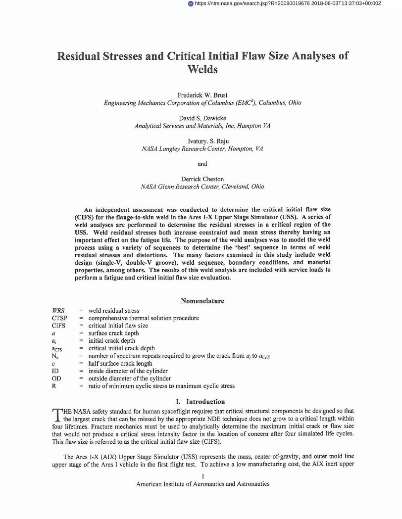
The flange-to-skin or flange-to-shell weld was one of several weld joints used in the design of the USS. The flange-to-skin weld was located at the outermost diameter of the upper stage simulator and is in the primary load path of the flight test vehicle (Figure 1). The USS consists of several "tuna can" segments that were approximately 5.5 m in (216 in.) diameter, 2.9 m (1 15 in.) tall, and 12.7 mm (0.5 in.) thick. A 152 mm (6 in.) wide by 25.4 mm (1 in.) thick flange was welded to the s k i and was used to Fasten adjacent tuna cans. Gussets were welded to the skin and flange every 10 degrees around the circumference of the %ma can". The flange-to-skin weld was a flux core bun weld with a fillet weld on the inside surface. The welding process often creates loss of fhsion defects in the weld that could develop into fatigue cracks and jeopardize the structural integrity of the Ares I-X vehicle.
A ClFS assessment was performed for the welds within the common segments designated US-1 through US-7 that share the same shell and flange designs. The US-l/US-2 interface flange-to-skin weld was chosen for the CIFS analysis because this interface experience the highest service loads. This flange-to-skin weld, with the gussets, represents a configuration that cannot be modeled using an axis-symmetric model. Moreover, the configuration is quite different 6om typical 'pipe or cylinder' type welds and the resulting residual stresses do not necessarily behave as conveutional intuition would predict.
In this paper the main features of the weld analysis are discussed and a brief summary of the CIFS assessment is presented. The purpose of this set of weld analyses was to model the weld process using a variety of sequences to determine the 'best' sequence in terms of weld residual stresses and distortions. The many factors examined in this study include weld design (single-V, double-V groove), weld sequence, boundary conditions, and material properties, among others. In addition, mesh refmement studies are presented. Full three dimensional weld analyses were performed. The results of this weld analysis were included with service loads (including fit-up stresses) to perform a fatigue and critical initial flaw size evaluation.
Figure 1 ARES Space Vehicle and 'Tuna Can' Segment Design.
2 American Institute of Aeronautics and Astronautics
11. Weld Analysis Procedure Computational weld modeling is challenging because many of the processes of welding are highly nonlinear.
The sources of nonlinearity are due to material melting and re-solidification, very high transient thermal gradients, and non-linear temperature dependent plastic straining and phase transformations, Moreover, for weld modeling to have practical advantages in industrial production, computational solution times must be manageable since an optimum weld design of large, complex fabrications requires numerous and separate analyses.
Most computational weld models that were available commercially are mathematics- and physics-based models. The following is a brief description of the V F T ~ ~ (Virtual Fabrication Technology, VFT) code, see Reference 1. Other codes were also available for predicting and controlling weld residual stresses and distortions. There were two main analysis modules, the thermal model and the structural model, that make up the weld process simulation methodology in VFT. These modules are briefly summarized below. Welding distortion simulation normally adopts sequentially coupled thermal structural analysis. The thermal analysis is performed and then the structural analysis is performed using the temperatures predicted by the thermal analysis as the thermal load in conjunction with any additional mechanical loads or constraints. Material response in a welding process is very much localized along the welds. For large fabricated structures, the simulations involve millions of degrees of freedom and are highly nonlinear, and hence are extremely computationally intensive. As such, coarse meshes are generally used for the global distortion predictions. However, numerical thermal predictions using such coarse meshes are inadequate, especially for capturing the thermal gradients and cooling rates during welding processes. Developing efficient and effective simulation procedures that take into account these contrasting requirements is crucial to practically and successfully applying welding simulations to large problems.
ThermalSolutions and CTSF! The Comprehensive Thermal Solution Procedure (CTSP) [4,5,8-101 was developed based on superposition of complicated closed form analytical expressions and developed heat source theories. CTSP is very rapid and is used for large problems. Numerical thermal solutions based on a modification of Goldak theory are also used, but these solutions often take a long time to perform for large problems. CTSP is a closed form solution thermal analysis code specifically developed for global distortion and residual stress prediction of production components such as the Ares I-X. The code is an analytical solution based on the Rosenthal solution of a point heat source moving in an infmite domain at a constant direction and speed. Without additional treatment, the Rosenthal solution cannot be used to calculate the temperature profiles for industrial applications. To simulate the surface of a component, CTSP uses the imaginary heat sources reflected on the surface of the component to achieve the equivalent heat conduction. Meanwhile, CTSP uses the "negative" heat sources starting at the time of welding end to simulate the stop of the welding and transients [X-101. The CTSP solutions were used here because they have been shown to be very accurate for large problems and solution times are on the order of several minutes compared with hours and days for a full numerical thermal solution.
Using these techniques, CTSP was able to simulate typical weld joint types such as groove joints, lap joints, T- fillet joints, traverse complex welds, and multiple weld paths. During the development of the VFT code, numerous validation examples were used to drive the code development (see References 1-10 and the many references sited therein). These validations were made with both thermocouple measurements of test components and full numerical thermal solutions using DFLUX user routines in conjunction with the commercial finite element analysis code ABAQUS". The details on CTSP have been well documented and reported in the literature and the advantages and essential features are highlighted as follows:
Sructural Solution and Weld Constitutive Model. The structural model was developed based on ABAQUS commercial finite element codes by implementing a special materials module that includes a constitutive law that permits stress relief due to weld meltinghe-melting effects, strain hardening effects, large deformation mechanisms, rapid weld metal deposition features, phase transformation plasticity @ased on the Leblond model [2]), etc. Experience suggests that uncoupled thermaVstructural solutions for weld problems were accurate in all weld models. Moreover, visco-plastic (or creep) effects were not important since the time spent in the creep regime during welding was negligible. However, creep effects were permitted and were often used to model heat treatments of steels and stress relief due to heat treatment. The constihltive model library permits isotropic, kinematic, and mixed hardening (Lemaitre-Chaboche). Here isotropic hardening was used and tends to produce upper bound stress
3 American Institute of Aeronautics and Astronautics
results. Many more details of the VFT code, with many example solutions, can be found in References 1-10 and in the many references therein.
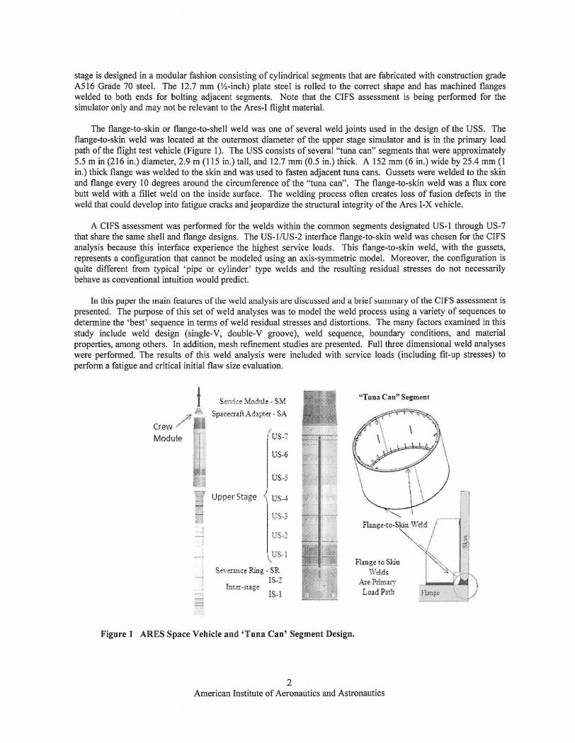
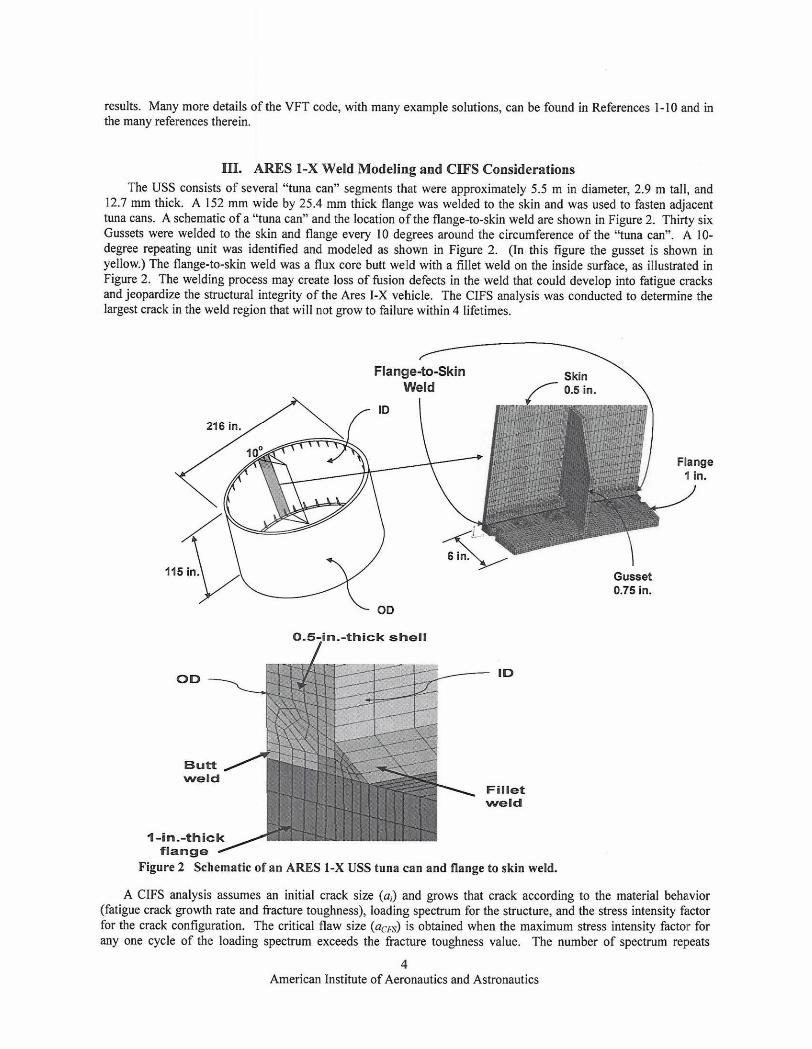
III. ARES 1-X Weld Modeling and CIFS Considerations The USS consists of several "tuna can" segments that were approximately 5.5 m in diameter, 2.9 m tall, and
12.7 mm thick. A 152 mm wide by 25.4 mm thick flange was welded to the s k i and was used to fasten adjacent tuna cans. A schematic of a "tuna can" and the location of the flange-to-skin weld are shown in Figure 2. Thirty six Gussets were welded to the skim and flange every 10 degrees around the circumference of the "tuna can". A 10- degree repeating unit was identified and modeled as shown in Figure 2. (In this figure the gusset is shown in yellow.) The flange-to-ski weld was a flux core butt weld with a fillet weld on the inside surface, as illustrated in Figure 2. The welding process may create loss of fusion defects in the weld that could develop into fatigue cracks and jeopardize the structural integrity of the Ares I-X vehicle. The CIFS analysis was conducted to determine the largest crack in the weld region that will not grow to failure withim 4 lifetimes.
Skin Weld f l 0.5 in.
Gusset 0.75 in.
0.5-in.-thick shell /
flange Figure 2 Schematic of an ARES 1-X USS tuna can and flange to skin weld.
A CIFS analysis assumes an initial crack size (a,) and grows that crack accord'mg to the material behavior (fatigue crack growth rate and fiacture toughness), loading spectrum for the structure, and the stress intensity factor for the crack configuration. The critical flaw size (acFs) is obtained when the maximum stress intensity factor for any one cycle of the loadiig spectrum exceeds the fiilcture toughness value. The number of spectrum repeats
4 American Institute of Aeronautics and Astronautics
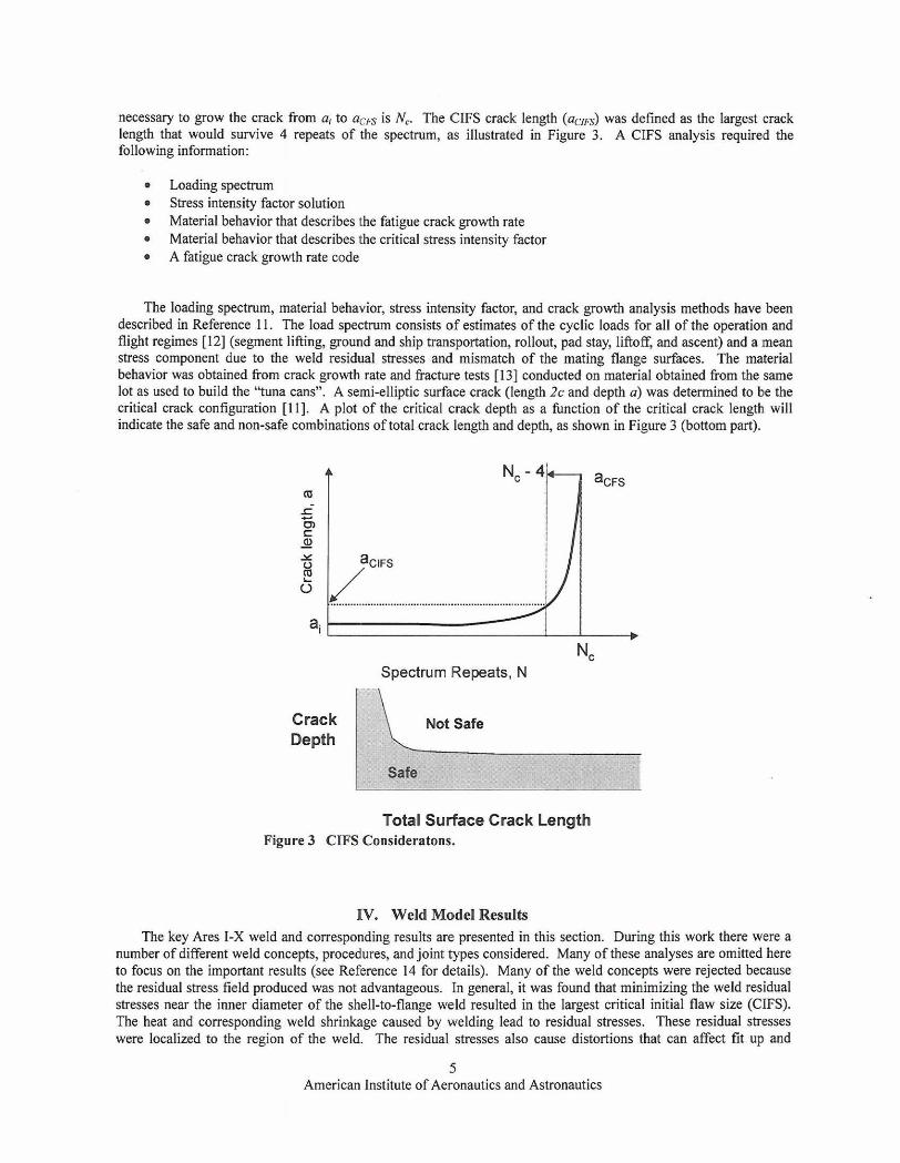
necessary to grow the crack from ai to acfis is N,. The CIFS crack length (anfis) was defined as the largest crack length that would survive 4 repeats of the spectrum, as illustrated in Figure 3. A CIFS analysis required the following information:
Loadimg spectrum Stress intensity factor solution Material behavior that describes the fatigue crack growth rate Material behavior that describes the critical stress intensity factor A fatigue crack growth rate code
The loading spectrum, material behavior, stress intensity factor, and crack growth analysis methods have been described in Reference 11. The load spectrum consists of estimates of the cyclic loads for all of the operation and flight regimes [12] (segment lifting, ground and ship transportation, rollout, pad stay, liftoff, and ascent) and a mean stress component due to the weld residual stresses and mismatch of the mating flange surfaces. The material behavior was obtained from crack growth rate and eacture tests 1131 conducted on material obtained from the same lot as used to build the "tuna cans". A semi-elliptic surface crack (length 2c and depth a) was determined to be the critical crack configuration [ll] . A plot of the critical crack depth as a function of the critical crack length will indicate the safe and non-safe combinations of total crack length and depth, as shown in Figure 3 @onom part).
Nc Spectrum Repeats , N
Total Surface Crack Length Figure 3 CIFS Consideratons.
IY. Weld Model Results The key Ares I-X weld and corresponding results are presented in this section. During this work there were a
number of different weld concepts, procedures, and joint types considered. Many of these analyses are omined here to focus on the important results (see Reference 14 for details). Many of the weld concepts were rejected because the residual stress field produced was not advantageous. In general, it was found that minimizing the weld residual stresses near the inner diameter of the shell-to-flange weld resulted in the largest critical initial flaw size (CIFS). The heat and corresponding weld shrinkage caused by welding lead to residual stresses. These residual stresses were localized to the region of the weld. The residual stresses also cause distortions that can affect fit up and
5 American Institute of Aeronautics and Astronautics
tolerance requirements throughout the component structure. The residual stresses in the shell and flange prior to welding were not considered in this analysis although in some cases these can be important [15].
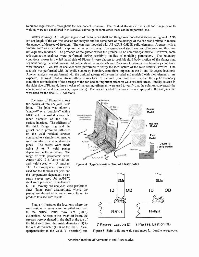
Weld Geomeny. A 10-degree segment of the tuna can shell and flange was modeled as shown in Figure 4. A 96 an arc length of the can was chosen for analysis and the remainder of the acreage of the can was omitted to reduce the number of degrees-of-freedom. The can was modeled with ABAQUS C3D8R solid elements. A gusset with a 'mouse hole' was included to capture the correct stiffness. The gusset weld itself was not of interest and thus was not explicitly modeled. The presence of the gusset causes the problem to he non-axis-symmetric. However, some axis-symmetric analyses were performed during sensitivity studies of modeling parameters. The boundary conditions shown in the left hand side of Figure 4 were chosen to prohibit rigid body motion of the flange ring segment during the weld process. At both ends of the model (0- and 10-degree locations), 6ee boundary conditions were imposed. Two sets of analyses were performed to verify the local nature of the weld residual stresses. One analysis was performed with the cyclic symmetry boundary conditions imposed at the 0- and 10-degree locations. Another analysis was performed with the omitted acreage of the can included and modeled with shell elements. As expected, the weld residual stress influence was local to the weld joint and hence neither the cyclic boundary conditions nor inclusion of the acreage of the can had an important effect on weld residual stress. Finally, as seen in the right side of Figure 4, three meshes of increasing refinement were used to verify that the solution converged (the course, medium, and fine models, respectively). The model labeled 'tine model' was employed in the analyses that were used for the final CIFS solutions.
The inset of Figure 4 shows the details of the analyzed weld joint. The joint was either a 'single-V' or a 'double-V' with a fillet weld deposited along the inner diameter of the shell- surface interface. The stiffness of the thick flange ring and the gusset had a profound influence on the weld residual stresses compared to a simple shell groove weld (similar to a large diameter pipe). The welds were made using 5 to 7 weld passes depending on the sequence. The range of weld parameters were: Amps = 20& 215, Volts = 25-26, and- weld speed = 4-5 mmfsec. Figure 4 Typical cross section of a laser notch. The thermo-physical properties used for the thermal analysis and the temperature dependent stress strain curves used for A516-70 steel were presented in Reference 6. Full moving arc analyses were performed since 'lump pass' assumptions, where the passes are deposited at once, were found to
OD produce less accurate results.
Figure 4 illustrates the locations where the weld residual stresses were compiled and used in the critical initial flaw size (CIFS) evaluations. As seen in the lower left insert, the stresses were evaluated in the shell at the toe of the fillet weld from the inside diameter (ID) to 7 passes, ~~~t~~ ID 7 passes, ~~~t on OD the outside diameter (OD) of the shell. Axial (perpendicular to the weld, Y- direction) and Figure 5 Skin to flange weld sequences for double vegroove.
American Institute of Aeronautics and Astronautics
hoop (the weld travel, Z-direction or circumferential direction) residual stresses were compiled at locations illustrated in Figure 4. Cut plane 0 ran through the first full hole, cut plane 1 was through the second hole, cut plane 2 was at the gusset 'mouse hole' location, and cut plane 3 was on the other side of the gusset near the weld stop location as illustrated in Figure 4. The stresses at other locations (including the possibility of cracks in the ring) were also considered for the CIFS analysis, but it was determined that circumferential crack growth (caused by axial shell stresses at the toe of the weld) were most critical. More details of this analysis can be found in References [I 1- 151.
Weld Sequences. A number of factors determine the final weld residual stress and distortion state and weld modeling is oiten used to design weld methods to either minimize or control residual stresses andlor distortions. Some of the many techniques that have been developed were discussed in detail in References 4 and 5 . Some of these factors include weld sequence, weld groove geometry, weld parameters, weld piece constraint, tacking methods, use of heat sinks, thermal tensioning, weld electrode used, and special methods such as pre-cambering, pre-bend, post weld heat treat, among many others. The weld groove geometry and weld sequence were key contributing factors in developing a favorable or unfavorable weld residual stress state in the Ares I-X welds. The weld definitions and weld sequences presented here were defined by the USS design team. A key conclusion 6om this weld modeling work, which is discussed in detail later, is that the final pass should be deposited at the outer diameter (OD) of the shell to flange weld as illustrated in Figure 5.
The original weld sequence considered was single-V weld geometry (note that Figure 5 only shows a double-V configuration). The fillet weld was deposited fast and then the weld joint is sequentially filled 6om the ID to the OD for a single-V groove. This type of weld joint will typically result in larger out of plane weld distortions since the weld shrinkage progresses from the ID to OD as each pass is deposited. Figure 5 shows the weld sequence for a balanced double-V weld. This weld was balanced about the mid thickness of the shell, tending to minimize the distortions.
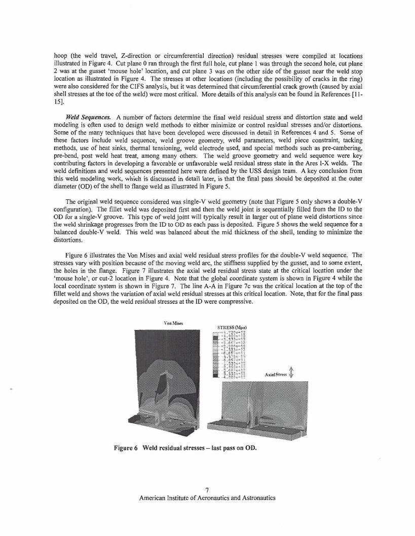
Figure 6 illustrates the Von Mises and axial weld residual stress profiles for the douhle-V weld sequence. The stresses vary with position because of the moving weld arc, the sti&ess supplied by the gusset, and to some extent, the holes in the flange. Figure 7 illustrates the axial weld residual stress state at the critical location under the 'mouse hole', or cut-2 location in Figure 4. Note that the global coordimate system is shown in Figure 4 while the local coordinate system is shown in Figure 7. The line A-A in Figure 7c was the critical location at the top of the fillet weld and shows the variation of axial weld residual stresses at this critical location. Note, that for the fmal pass deposited on the OD, the weld residual stresses at the ID were compressive.
Figure 6 Weld residual stresses - last pass on OD.
7 American Institute of Aeronautics and Astronautics
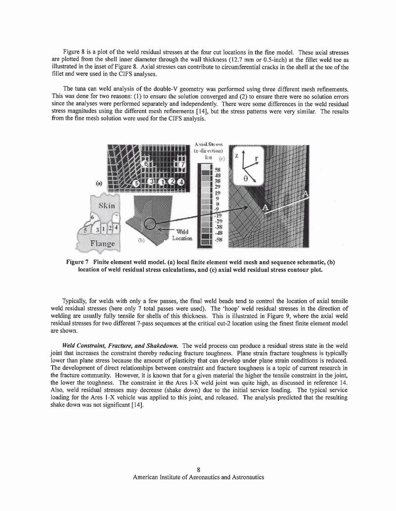
Figure 8 is a plot of the weld residual stresses at the four cut locations in the fine model. These axial stresses are plotted from the shell inner diameter through the wall thichess (12.7 mm or 0.5-inch) at the fillet weld toe as illustrated in the inset of Figure 8. Axial stresses can contribute to circumferential cracks in the shell at the toe of the fillet and were used in the CIFS analyses.
The tuna can weld analysis of the double-V geometry was performed using three different mesh refinements. This was done for two reasons: (1) to ensure the solution converged and (2) to ensure there were no solution errors since the analyses were performed separately and independently. There were some differences in the weld residual stress magnitudes using the different mesh refmements [14], but the stress patterns were very similar. The results from the fine mesh solution were used for the CIFS analysis.
Figure 7 Finite element weld model. (a) local finite element weld mesh and sequence schematic, (b) location of weld residual stress calculatinos, and (c) axial weld residual stress contour plot.
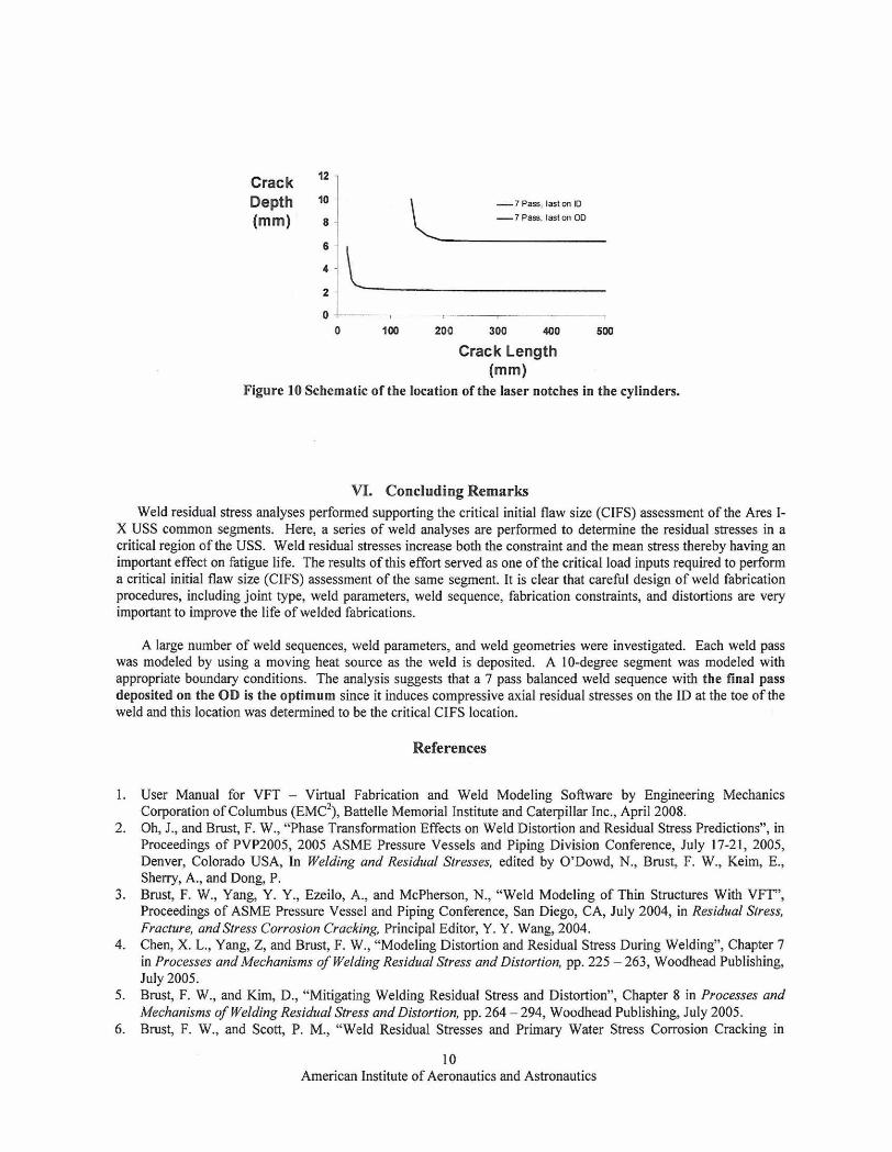
Typically, for welds with only a few passes, the final weld beads tend to control the location of axial tensile weld residual stresses (here only 7 total passes were used). The 'hoop' weld residual stresses in the direction of welding are usually fully tensile for shells of this thichess. This is illustrated in Figure 9, where the axial weld residual stresses for two different 7-pass sequences at the critical cut-2 location using the finest finite element model are shown.
Weld Constraint, Fracture, andShakedown. The weld process can produce a residual stress state in the weld joint that increases the constraint thereby reducing hcture toughness. Plane strain liacture toughness is typically lower than plane stress because the amount of plasticity that can develop under plane strain conditions is reduced. The development of direct relationships between constraint and fracture toughness is a topic of current research in the hcture community. However, it is known that for a given material the higher the tensile constraint in the joint, the lower the toughness. The constraint in the Ares I-X weld joint was quite high as discussed in reference 14. Also, weld residual stresses may decrease (shake down) due to the initial senrice loading. The typical service loading for the Ares 1-X vehicle was applied to this joint, and released. The analysis predicted that the resulting shake down was not significant [14].
8 American Institute of Aeronautics and Astronautics
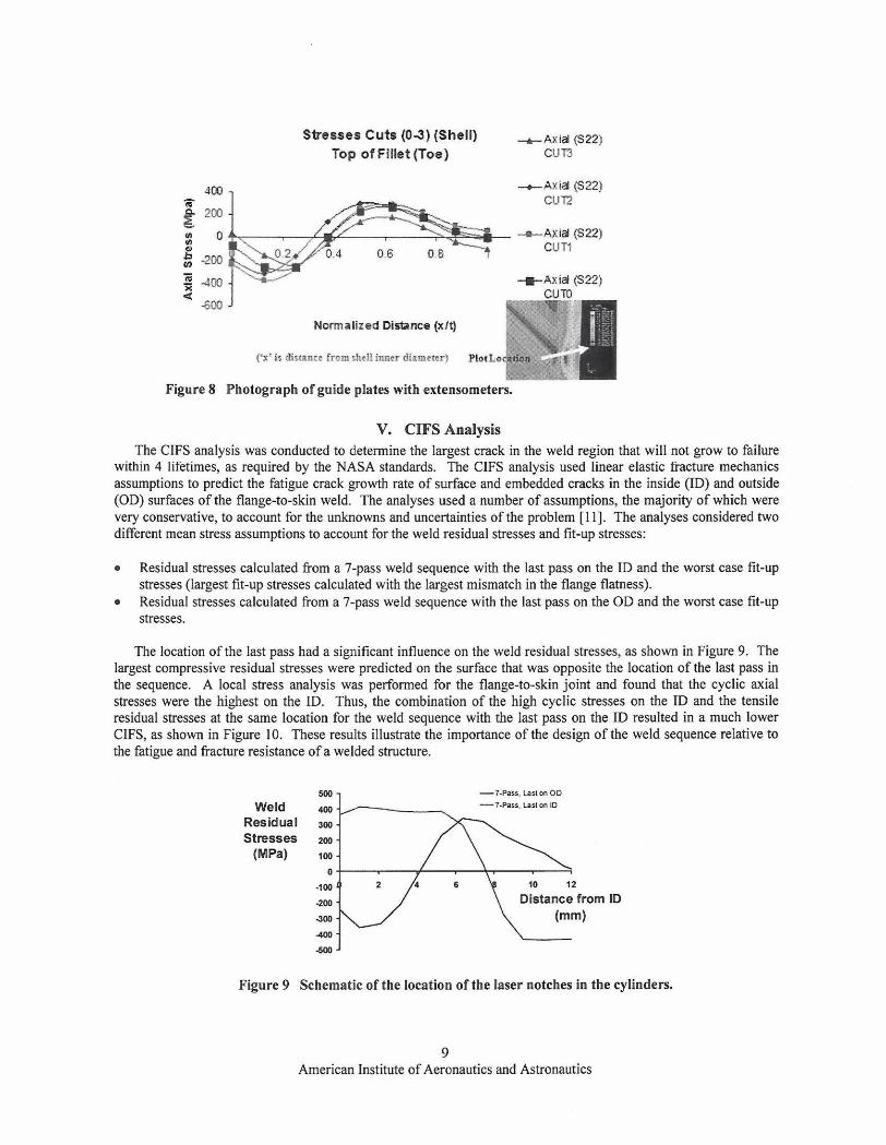
Sireases Cuts (09) (Shell) (5F221
Top of Fillet (Toe) cum
400 -AXU (S22f CUT2 1 200 - 0
(d : -200 - 2 400 +Axid (522) < cum
400
Nmnrlized Dlrtrnca el9
Figure 8 Photograph of guide plates with extensometers.
V. CIFS Analysis The CIFS analysis was conducted to determine the largest crack in the weld region that will not grow to failure
withln 4 lifetimes, as required by the NASA standards. The ClFS analysis used linear elastic hcture mechanics assumptions to predict the fatigue crack growth rate of surface and embedded cracks in the inside (ID) and outside (OD) surfaces of the flange-to-skin weld. The analyses used a number of assumptions, the majority of which were very conservative, to account for the unknowns and uncertainties of the problem [ll]. The analyses considered two different mean stress assumptions to account for the weld residual stresses and fit-up stresses:
Residual stresses calculated from a 7-pass weld sequence with the last pass on the ID and the worst case fit-up stresses (largest fit-up stresses calculated with the largest mismatch in the flange flatness). Residual stresses calculated from a 7-pass weld sequence with the last pass on the OD and the worst case fit-up stresses.
The location of the last pass had a significant influence on the weld residual stresses, as shown in Figure 9. The largest compressive residual stresses were predicted on the surface that was opposite the location of the last pass in the sequence. A local stress analysis was performed for the ilange-to-skin joint and found that the cyclic axial stresses were the highest on the ID. Thus, the combination of the high cyclic stresses on the ID and the tensile residual stresses at the same location for the weld sequence with the last pass on the ID resulted in a much lower CIFS, as shown in Figure 10. These results illustrate the importance of the design of the weld sequence relative to the fatigue and fracture resistance of a welded structure.
-7-P.U, U i l O n OD -7.P.Is. L.*on !D
Residual Stresses 2 w
(MPa) IW
.I w i w Distance from ID 4w MO
d W
Figure 9 Schematic of the location of the laser notches in the cylinders.
9 American Institute of Aeronautics and Astronautics
Crack 12 -
Depth '0 -7 PW, lartan D
(mm) 8 -7 Pas. larlm OD
I
0 6.- 7 . ----- ,- 0 1W 200 300 400 5W
Crack Length (mm)
Figure 10 Schematic of the location of the laser notches in the cylinders.
VI. Concluding Remarks Weld residual stress analyses performed supporting the critical initial flaw size (CIFS) assessment of the Ares I-
X USS common segments. Here, a series of weld analyses are performed to determine the residual stresses in a critical region of the USS. Weld residual stresses increase both the constraint and the mean stress thereby having an important effect on fatigue life. The results of this effort served as one of the critical load inputs required to perform a critical initial flaw size (CIFS) assessment of the same segment. It is clear that careful design of weld fabrication procedures, including joint type, weld parameters, weld sequence, fabrication constraints, and distortions are very important to improve the life of welded fabrications.
A large number of weld sequences, weld parameters, and weld geometries were investigated. Each weld pass was modeled by using a moving heat source as the weld is deposited. A 10-degree segment was modeled with appropriate boundary conditions. The analysis suggests that a 7 pass balanced weld sequence with the final pass deposited on the OD is the optimum since it induces compressive axial residual stresses on the ID at the toe of the weld and this location was determined to be the critical CIFS location.
References
1. User Manual for VFT - Virtual Fabrication and Weld Modeling Software by Engineering Mechanics Corporation of Columbus (EMC~), Battelle Memorial Institute and Caterpillar Inc., April 2008.
2. Oh, J., and Brust, F. W., "Phase Transformation Effects on Weld Distortion and Residual Stress Predictions", in Proceedings of PVP2005, 2005 ASME Pressure Vessels and Piping Division Conference, July 17-21, 2005, Denver, Colorado USA, In Welding and Residual Stresses, edited by O'Dowd, N., Brust, F. W., Keim, E., Sheny, A,, and Dong, P.
3. Brust, F. W., Yang, Y. Y., Ezeilo, A,, and McPherson, N., "Weld Modeling of Thin Structures With VFT", Proceedings of ASME Pressure Vessel and Piping Conference, San Diego, CA, July 2004, in Residual Stress, Fracture, andStress Corrosion Cracking, Principal Editor, Y . Y. Wang, 2004.
4. Chen, X. L., Yang, Z, and Brust, F. W., "Modeling Distortion and Residual Stress During Welding", Chapter 7 in Processes and Mechanisms of Welding Residual Stress andDistortion, pp. 225 - 263, Woodhead Publishing, July 2005.
5. Brust, F. W., and Kim, D., "Mitigating Welding Residual Stress and Distortion", Chapter 8 in Processes and Mechanisms of Welding Residual Stress and Distortion, pp. 264 - 294, Woodhead Publishing, July 2005.
6. Brust, F. W., and Scott, P. M., "Weld Residual Stresses and Primary Water Stress Corrosion Cracking in
10 American Institute of Aeronautics and Astronautics

Bimetal Nuclear Pipe Welds", PVP 2007-26297, Proceedimgs of the ASME PVP 2007lCreep 8 Conference, ASME, July 22-26,2007, San Antonio, Texas, USA.
7. Scott, P. M., Bmst, F. W., et al, "The Battelle Integrity of Nuclear Piping (BMP) Final Report", Nuclear Regulatory Commission Report NUREGICR-6837, Vol. 1 and 2, Prepared by Battelle and Engineering Mechanics Corp., June 2005.
8. Feng, Z., (Editor), "Processes and Mechanisms of Weldimg Residual Stress and Distortion" Woodhead Publishing Company, Cambridge, UK, 2005.
9. Cao, Z. Bmst, F. W., Nanjundan, A., Dong, Y., and Jutla, T., "A Comprehensive Thermal Solution Procedure for Different Weld Joints", Advances in Computational Engineering and Sciences; ed. S. N. Atluri and F. W. Bmst, Tech Science hess, pp 630-636, August 2000.
10. Bmst, F. W., Jutla, T., Yang, Y., Cao, Z., Dong, Y., Nanjundan, A,, Chen, X. L., Advances in Computational Engineering and Sciences; ed. S. N. Atluri and F. W. Brust, Tech Science Press, pp 630-636, August 2000. Also, Numerous Weld Papers in this set of volumes on Weld modeling by these authors.
11. Dawicke, D. S., I. S. Raju, and D. J. Cheston, "Critical Initial Flaw Size Analysis," NASA TM-215337, August 2008.
12. Larson, C., "Ares I-X USS Fracture Analysis Loads Spectra Development," NASA TM, August 2008. 13. Dawicke, D. S., Smith, S. A., and Raju, I. S. "Ares I-X USS Material Testing," NASA TM-215338, August
2008. 14. F. W. Bmst, I. S. Raju, and D. Cheston "Ares I-X USS Weld Residual Stress Analysis", NASA TM-215339,
2008. 15. Knight, N. F., Jr., Phillips, D. R., and Raju, I. S., "ARES I-X Upper Stage Simulator Structural Analyses
Supporting the NESC Critical Initial Flaw Size Assessment", NASA TM-2008-215336,2008.
11 American Institute of Aeronautics and Astronautics


![Prediction of welding residual stresses using machine ... · characterise the distribution of residual stresses in structural welds [6, 7]. With the development of residual stress](https://img.pdfslide.us/doc/110x75/5fa3f63f3be93a3412525cc3/prediction-of-welding-residual-stresses-using-machine-characterise-the-distribution.jpg)