Embed Size (px)
Citation preview
Civil 3D 2016 1 Rev. 3/2017
100.0 NRCS MINNESOTA MINNESOTA STANDARD SURVEY POINT CODES
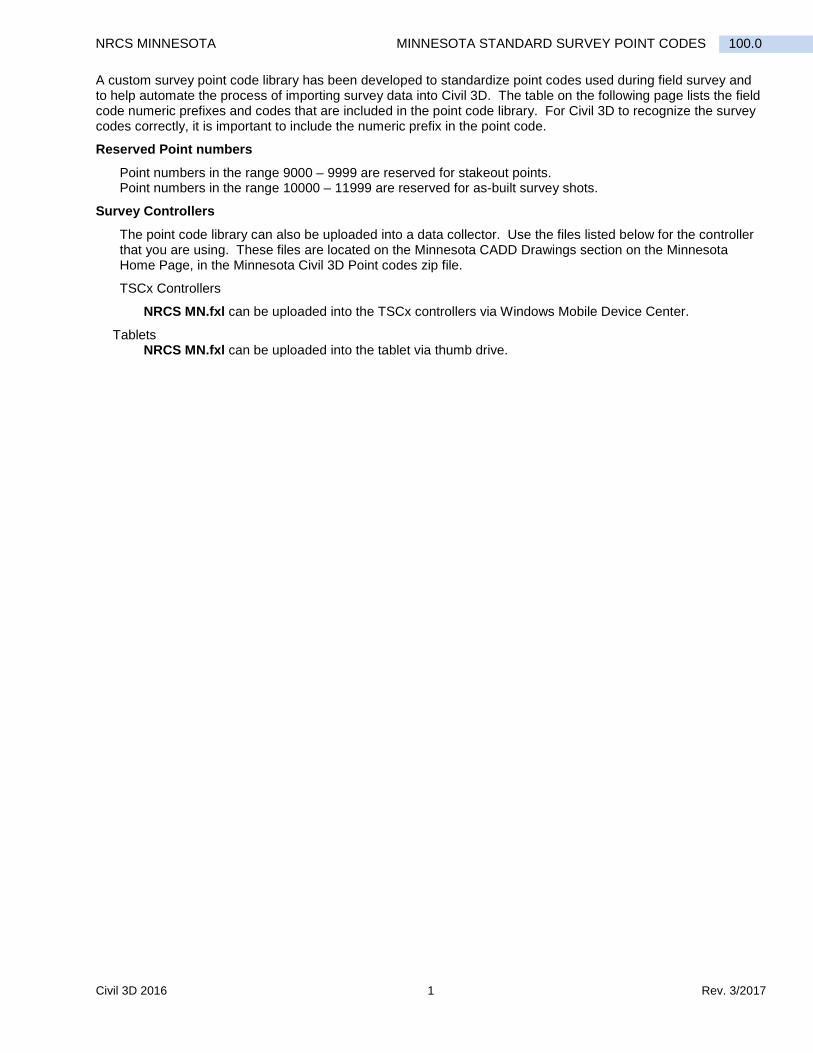
A custom survey point code library has been developed to standardize point codes used during field survey and to help automate the process of importing survey data into Civil 3D. The table on the following page lists the field code numeric prefixes and codes that are included in the point code library. For Civil 3D to recognize the survey codes correctly, it is important to include the numeric prefix in the point code.
Reserved Point numbers
Point numbers in the range 9000 – 9999 are reserved for stakeout points. Point numbers in the range 10000 – 11999 are reserved for as-built survey shots.
Survey Controllers
The point code library can also be uploaded into a data collector. Use the files listed below for the controller that you are using. These files are located on the Minnesota CADD Drawings section on the Minnesota Home Page, in the Minnesota Civil 3D Point codes zip file.
TSCx Controllers
NRCS MN.fxl can be uploaded into the TSCx controllers via Windows Mobile Device Center.
Tablets NRCS MN.fxl can be uploaded into the tablet via thumb drive.
Rev. 3/2017 2 Civil 3D 2016
MINNESOTA STANDARD SURVEY POINT CODES NRCS MINNESOTA 100.0
NRCS MN Field Code Library
01 TBM Temporary Benchmark
Con
trol
/Gro
und
Shot
s
02 BM Permanent Benchmark 03 IP Instrument Point 04 TP Turning Point 05 RP Reference Point 06 PPIN Property Pin or Marker 07 EPIN Easement Pin or Marker 08 GS Ground Shot 09 TH Soil Boring (Test Hole)
Stru
ctur
es
10 BLD Building 20 FX Fence
Bou
ndar
y Sh
ots 11 BLDC Building Corner 21 FC Fence Corner
12 CON Concrete 22 FJ Fence Junction 13 CONC Concrete Corner 23 FE Fence End 14 BIT Bituminous Pavement 24 FG Fence Gate 15 CLDAM Centerline of Dam 25 PL Property Line 16 EDAM Top Edge of Dam 26 EL Easement Line 17 WELL Well 27 ROW Right-of-Way Line 18 WALL Retaining Wall 28 EFLD Edge of Field 19 STRUC Other Structure 29 EWET Edge of Wetland
Wat
er F
eatu
res
30 CLW Centerline of Watercourse 40 CLR Centerline of Road
Roa
ds
31 CLDRAW Centerline of Draw 41 ER Edge of Road 32 CLDITCH Centerline of Ditch 42 CLFR Centerline of Field Road 33 EBL Edge of Bottom LDS 43 EFR Edge of Field Road 34 EBR Edge of Bottom RDS 44 CLD Centerline of Driveway 35 BNKL Bank LDS 45 ED Edge of Driveway 36 BNKR Bank RDS 46 RD Road Ditch Centerline 37 WL Water Line (Edge) 47 FLDA Field Approach 38 GSWET Ground Shot in Water 48 CLRR Centerline of Railroad 39 H2O Water Surface Elevation 49 ERR Edge of Railroad
Pipe
s/C
ulve
rts
50 RCPINV Reinforced Concrete Pipe Invert 60 CC Cropping Change
Vege
tatio
n
51 RCPTOP Reinforced Concrete Pipe Top 61 VC Vegetation Change 52 CMPINV Corrugated Metal Pipe Invert 62 EWOOD Edge of Woods 53 CMPTOP Corrugated Metal Pipe Top 63 TREEL Tree Line 54 PVC PVC Pipe 64 CTREE Coniferous Tree 55 HDPE HDPE Pipe 65 DTREE Deciduous Tree 56 APRON Pipe Apron 66 SHRUB Shrub 57 INTAKE Tile Intake 67 BRUSH Brush 58 OUTLET Tile Outlet 68 ROCK Rock or Rock Pile 59 TILEFL Tile Flowline 69
Util
ities
70 PP Power Pole 80 WD Watershed Divide
Terr
ain
71 PLO Overhead Power Line 81 SB Slope Break 72 PLB Buried Power Line 82 TS Top of Slope 73 TEL Telephone Line 83 BS Bottom of Slope 74 GAS Gas Line 84 LS Low Spot 75 WATER Water Line (Pipe) 85 HS High Spot 76 FIBER Fiber Optic Line 77 UTIL Other Utility Line 78 PED Pedestal (phone, electric, etc.) 79 GW Guy Wire
GPS Survey Manual 1 Rev. 3/2017
114.0 NRCS MINNESOTA GPS SURVEY MANUAL – MEASURE POINTS PROCEDURE
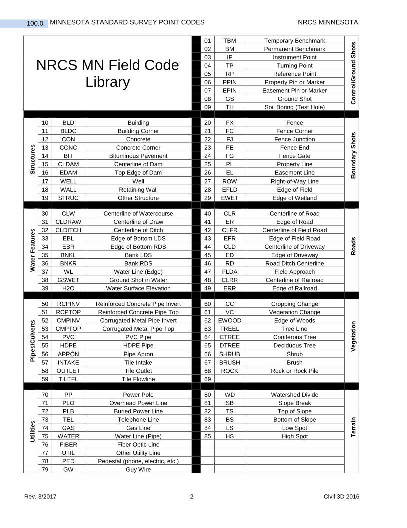
Measure Points Procedures 1. Choose Measure points 2. Enter Point name:
or click on > to view the dropdown. Point name is a number, it is useful to reserve 1 to 99 for control points. Start with 100 for all the other shots, you may desire to set up a numerical system to readily distinguish different Codes eg; 1000 – 1999 for watershed divide, 2000 – 2999 for centerline of draw, 3000 – 9999 for ground shots and so forth.

Rev. 3/2017 2 GPS Survey Manual
GPS SURVEY MANUAL – MEASURE POINTS PROCEDURE NRCS MINNESOTA 114.0
3. Enter Code: or click on > to view the dropdown. Code is a description of the shot you are taking, descriptions have been selected and are to be used for ALL SURVEYS. For more information on the Minnesota field code library, refer to Quick Reference Guide 100.0 Minnesota Standard Survey Point Codes.

GPS Survey Manual 3 Rev. 3/2017
114.0 NRCS MINNESOTA GPS SURVEY MANUAL – MEASURE POINTS PROCEDURE
Rev. 3/2017 4 GPS Survey Manual
GPS SURVEY MANUAL – MEASURE POINTS PROCEDURE NRCS MINNESOTA 114.0
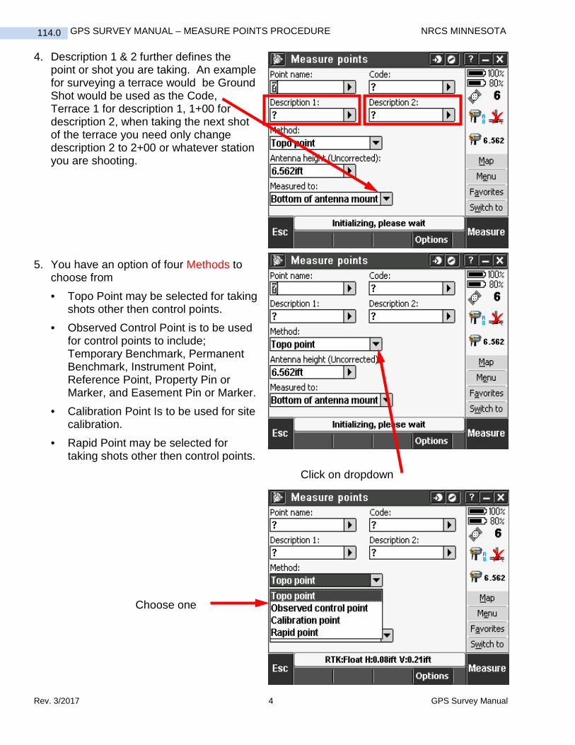
4. Description 1 & 2 further defines the point or shot you are taking. An example for surveying a terrace would be Ground Shot would be used as the Code, Terrace 1 for description 1, 1+00 for description 2, when taking the next shot of the terrace you need only change description 2 to 2+00 or whatever station you are shooting.
5. You have an option of four Methods to
choose from • Topo Point may be selected for taking
shots other then control points. • Observed Control Point is to be used
for control points to include; Temporary Benchmark, Permanent Benchmark, Instrument Point, Reference Point, Property Pin or Marker, and Easement Pin or Marker.
• Calibration Point Is to be used for site calibration.
• Rapid Point may be selected for taking shots other then control points.
Click on dropdown
Choose one
GPS Survey Manual 5 Rev. 3/2017
114.0 NRCS MINNESOTA GPS SURVEY MANUAL – MEASURE POINTS PROCEDURE
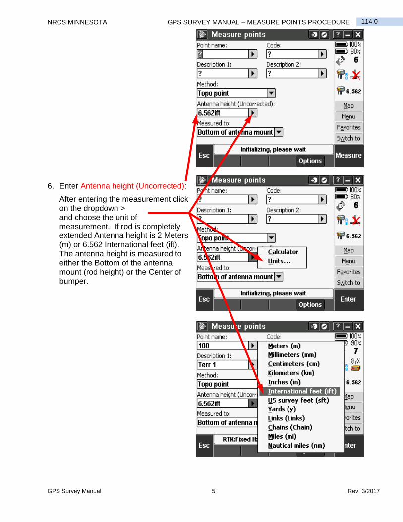
6. Enter Antenna height (Uncorrected):
After entering the measurement click on the dropdown > and choose the unit of measurement. If rod is completely extended Antenna height is 2 Meters (m) or 6.562 International feet (ift). The antenna height is measured to either the Bottom of the antenna mount (rod height) or the Center of bumper.

Rev. 3/2017 6 GPS Survey Manual
GPS SURVEY MANUAL – MEASURE POINTS PROCEDURE NRCS MINNESOTA 114.0
7. Measured to: is either "Bottom of antenna mount" or "Center of bumper" to change this click on the dropdown and click on the proper choice.
GPS Survey Manual 7 Rev. 3/2017
114.0 NRCS MINNESOTA GPS SURVEY MANUAL – MEASURE POINTS PROCEDURE
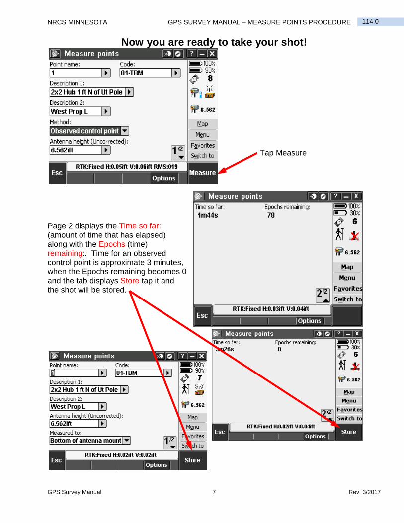
Now you are ready to take your shot!
Tap Measure
Page 2 displays the Time so far: (amount of time that has elapsed) along with the Epochs (time) remaining:. Time for an observed control point is approximate 3 minutes, when the Epochs remaining becomes 0 and the tab displays Store tap it and the shot will be stored.
Rev. 3/2017 8 GPS Survey Manual
GPS SURVEY MANUAL – MEASURE POINTS PROCEDURE NRCS MINNESOTA 114.0
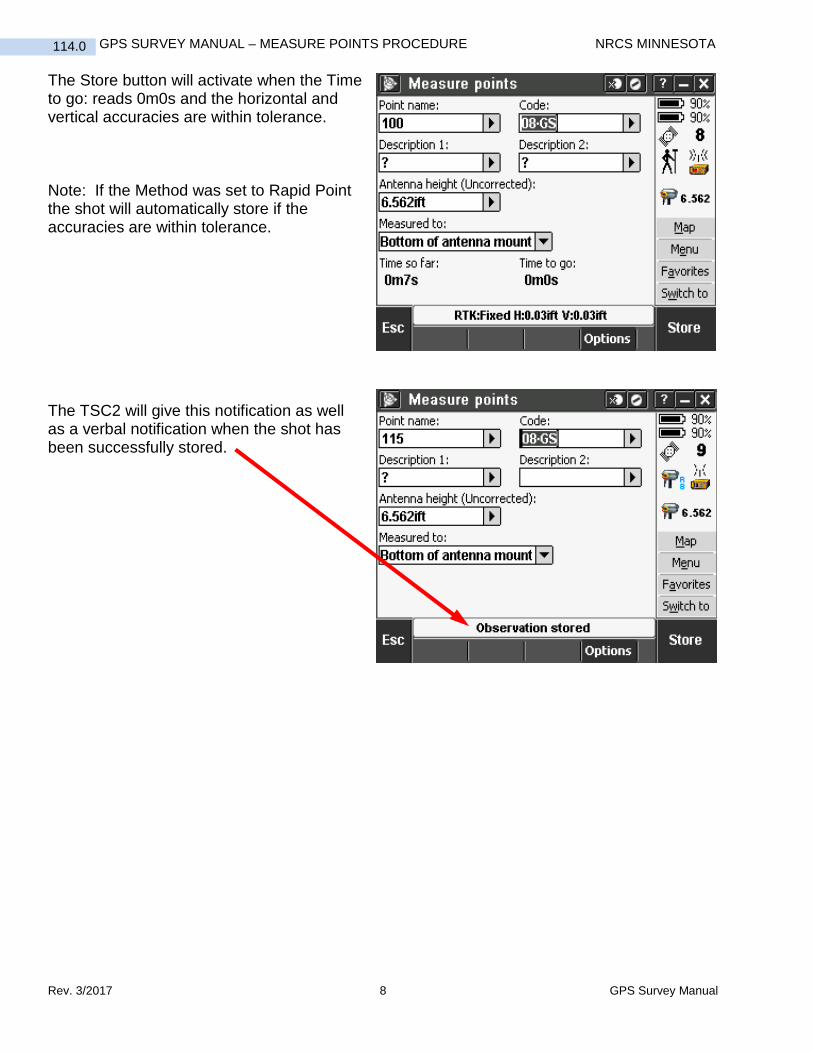
The Store button will activate when the Time to go: reads 0m0s and the horizontal and vertical accuracies are within tolerance. Note: If the Method was set to Rapid Point the shot will automatically store if the accuracies are within tolerance. The TSC2 will give this notification as well as a verbal notification when the shot has been successfully stored.
GPS Survey Manual 9 Rev. 3/2017
114.0 NRCS MINNESOTA GPS SURVEY MANUAL – MEASURE POINTS PROCEDURE
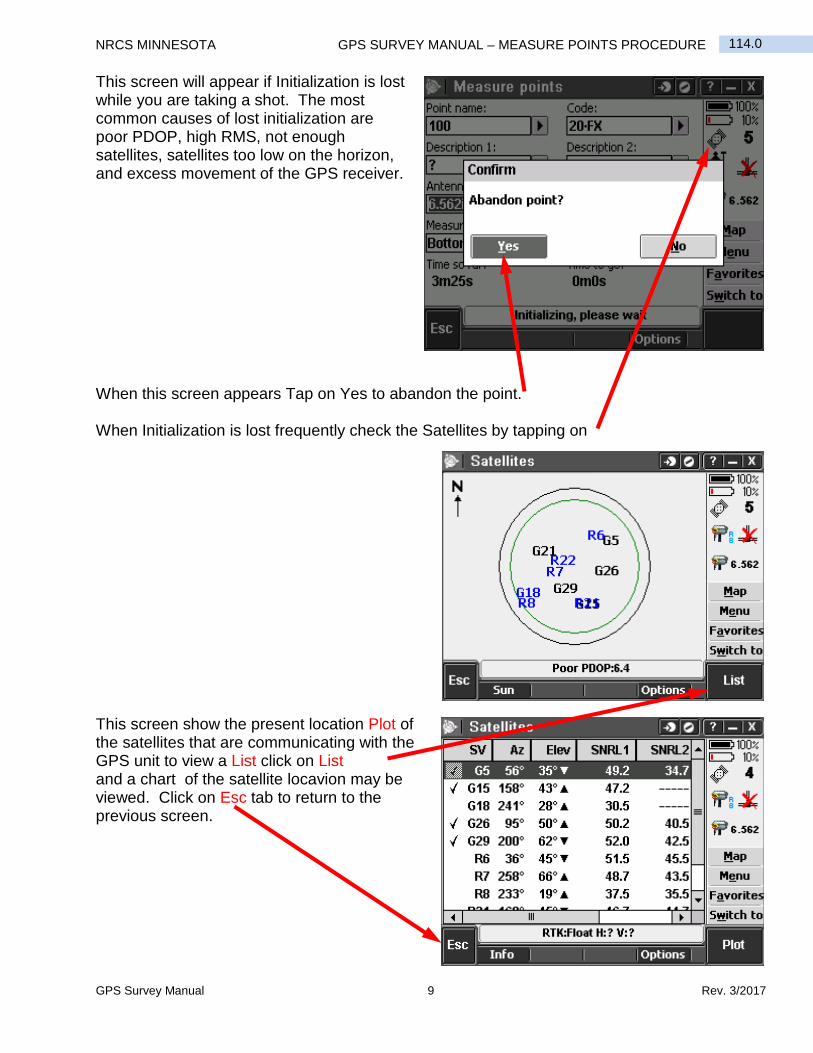
This screen will appear if Initialization is lost while you are taking a shot. The most common causes of lost initialization are poor PDOP, high RMS, not enough satellites, satellites too low on the horizon, and excess movement of the GPS receiver. When this screen appears Tap on Yes to abandon the point. When Initialization is lost frequently check the Satellites by tapping on This screen show the present location Plot of the satellites that are communicating with the GPS unit to view a List click on List and a chart of the satellite locavion may be viewed. Click on Esc tab to return to the previous screen.
Rev. 3/2017 10 GPS Survey Manual
GPS SURVEY MANUAL – MEASURE POINTS PROCEDURE NRCS MINNESOTA 114.0
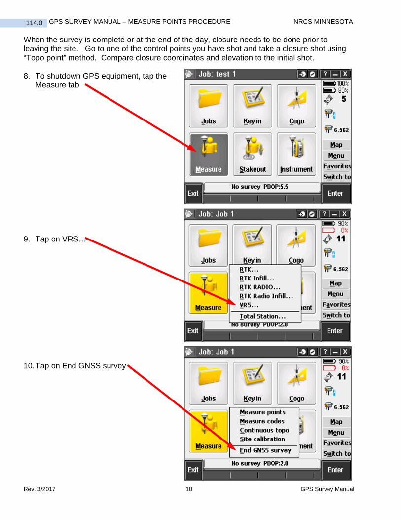
When the survey is complete or at the end of the day, closure needs to be done prior to leaving the site. Go to one of the control points you have shot and take a closure shot using “Topo point” method. Compare closure coordinates and elevation to the initial shot. 8. To shutdown GPS equipment, tap the
Measure tab 9. Tap on VRS… 10. Tap on End GNSS survey

GPS Survey Manual 11 Rev. 3/2017
114.0 NRCS MINNESOTA GPS SURVEY MANUAL – MEASURE POINTS PROCEDURE
11. Click Yes 12. You will also be asked if you would
like to Disconnect the Internet Connection. Click yes.
13. Turn controller off by tapping green button

GPS Survey Manual 1 Rev. 3/2017
116.0 NRCS MINNESOTA GPS SURVEY MANUAL – MEASURE CODES PROCEDURES
Measure Codes Procedures Using measure Codes allows the surveyor to switch between multiple point codes quickly and efficiently.
To begin using Measure Codes:
Click Measure
Click Measure codes
This screen may appear the first time Measure codes is used.
Click Add group and give the group a name.

Rev. 3/2017 2 GPS Survey Manual
GPS SURVEY MANUAL – MEASURE CODES PROCEDURES NRCS MINNESOTA 116.0
To assign a code to a box, tap and hold on the desired box.
Click in the Code field
Click on the desired code
Click enter
GPS Survey Manual 3 Rev. 3/2017
116.0 NRCS MINNESOTA GPS SURVEY MANUAL – MEASURE CODES PROCEDURES
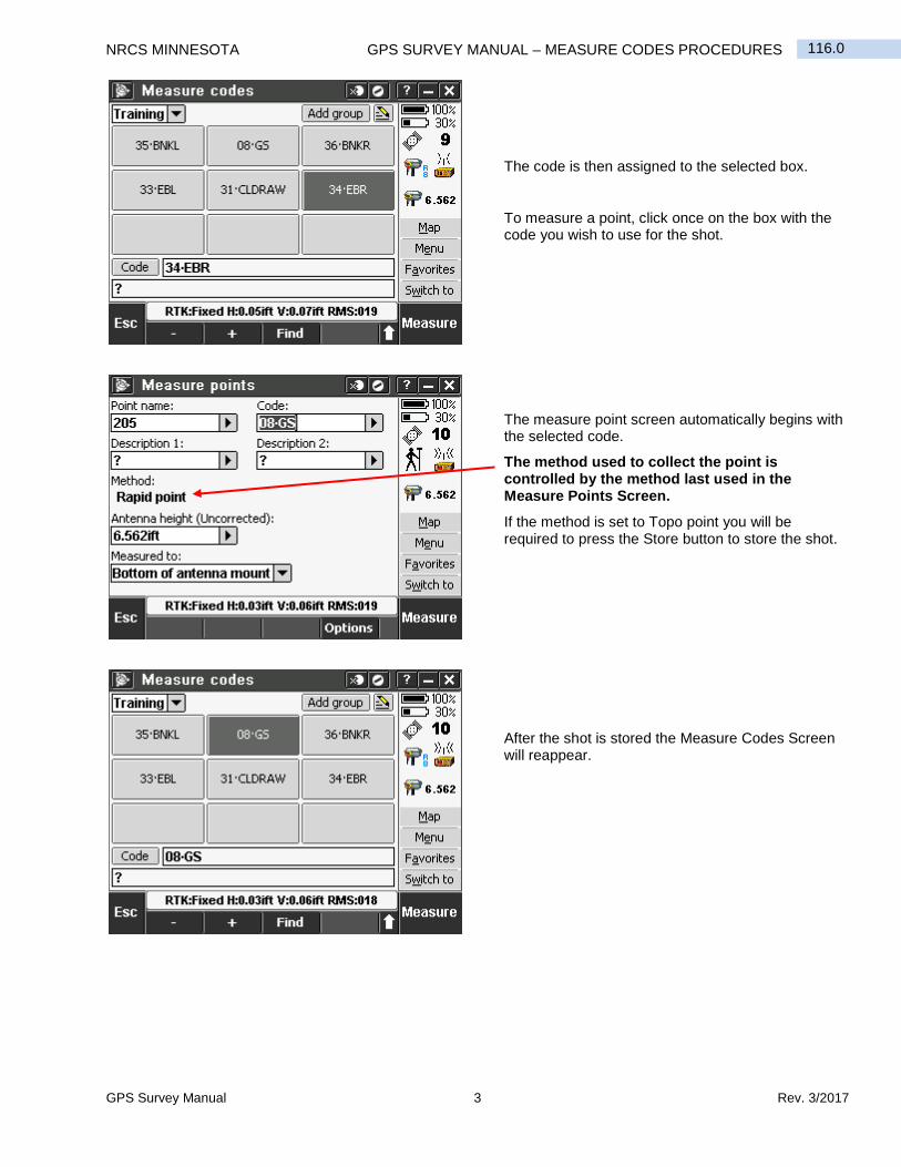
The code is then assigned to the selected box.
To measure a point, click once on the box with the code you wish to use for the shot.
The measure point screen automatically begins with the selected code.
The method used to collect the point is controlled by the method last used in the Measure Points Screen.
If the method is set to Topo point you will be required to press the Store button to store the shot.
After the shot is stored the Measure Codes Screen will reappear.
GPS Survey Manual 1 Rev. 3/2017
117.0 NRCS MINNESOTA GPS SURVEY MANUAL – STAKEOUT PROCEDURES
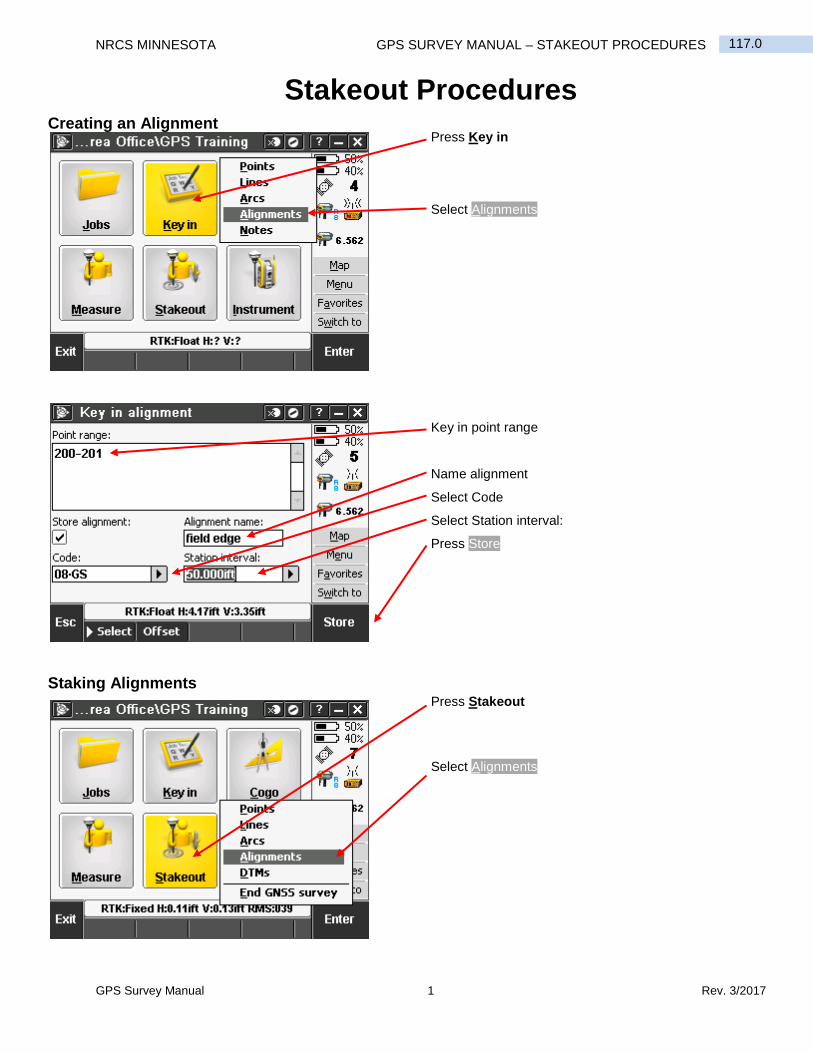
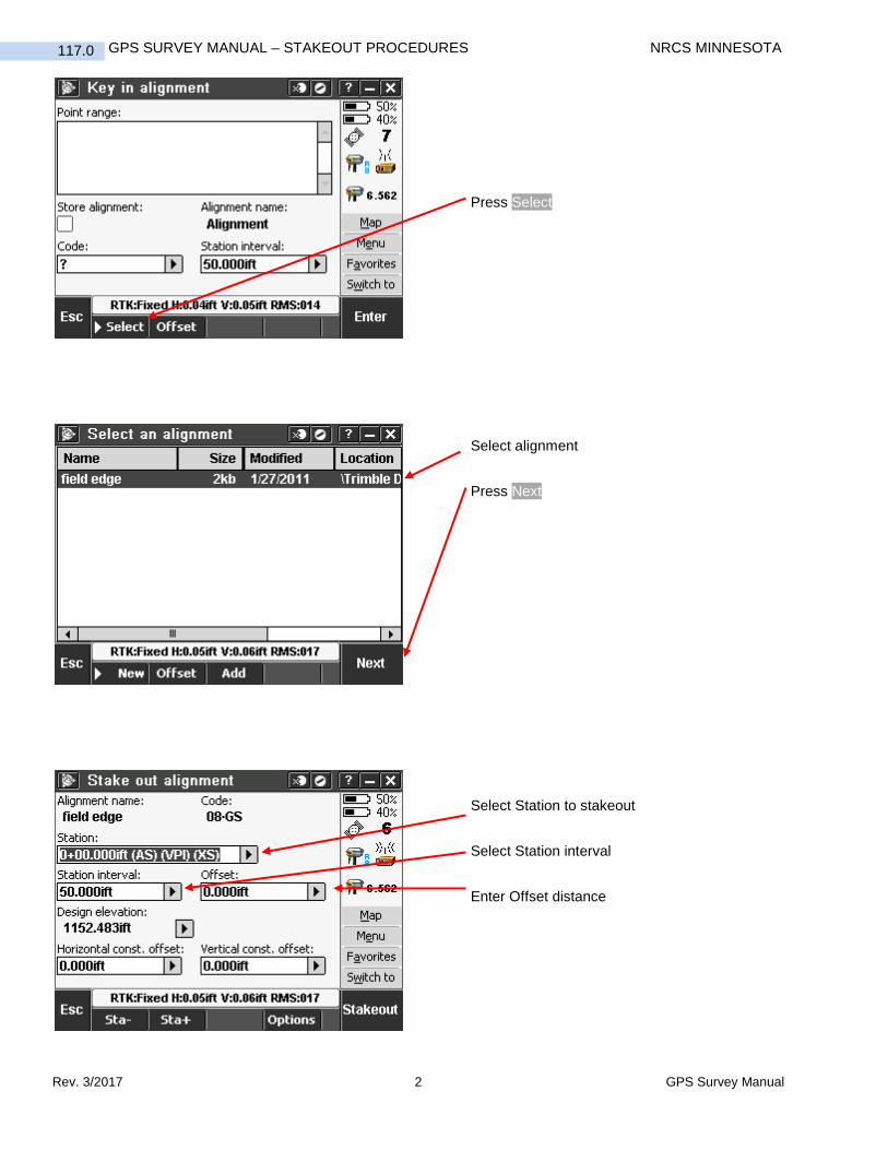
Stakeout Procedures Creating an Alignment
Staking Alignments
Press Key in
Select Alignments
Key in point range
Name alignment
Select Code
Select Station interval:
Press Store
Press Stakeout
Select Alignments
Rev. 3/2017 2 GPS Survey Manual
GPS SURVEY MANUAL – STAKEOUT PROCEDURES NRCS MINNESOTA 117.0
Press Select
Select alignment
Press Next
Select Station to stakeout
Select Station interval
Enter Offset distance

GPS Survey Manual 3 Rev. 3/2017
117.0 NRCS MINNESOTA GPS SURVEY MANUAL – STAKEOUT PROCEDURES
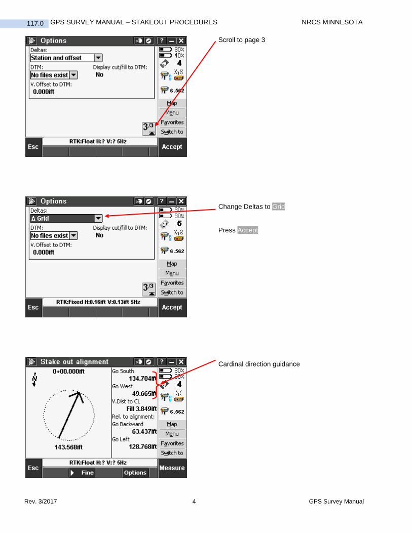
Select Direction to offset
Press Enter
Press Stakeout
To change the guidance information from Station/H. Offset to Cardinal directions:
Press Options
Rev. 3/2017 4 GPS Survey Manual
GPS SURVEY MANUAL – STAKEOUT PROCEDURES NRCS MINNESOTA 117.0
Scroll to page 3
Change Deltas to Grid
Press Accept
Cardinal direction guidance
GPS Survey Manual 5 Rev. 3/2017
117.0 NRCS MINNESOTA GPS SURVEY MANUAL – STAKEOUT PROCEDURES
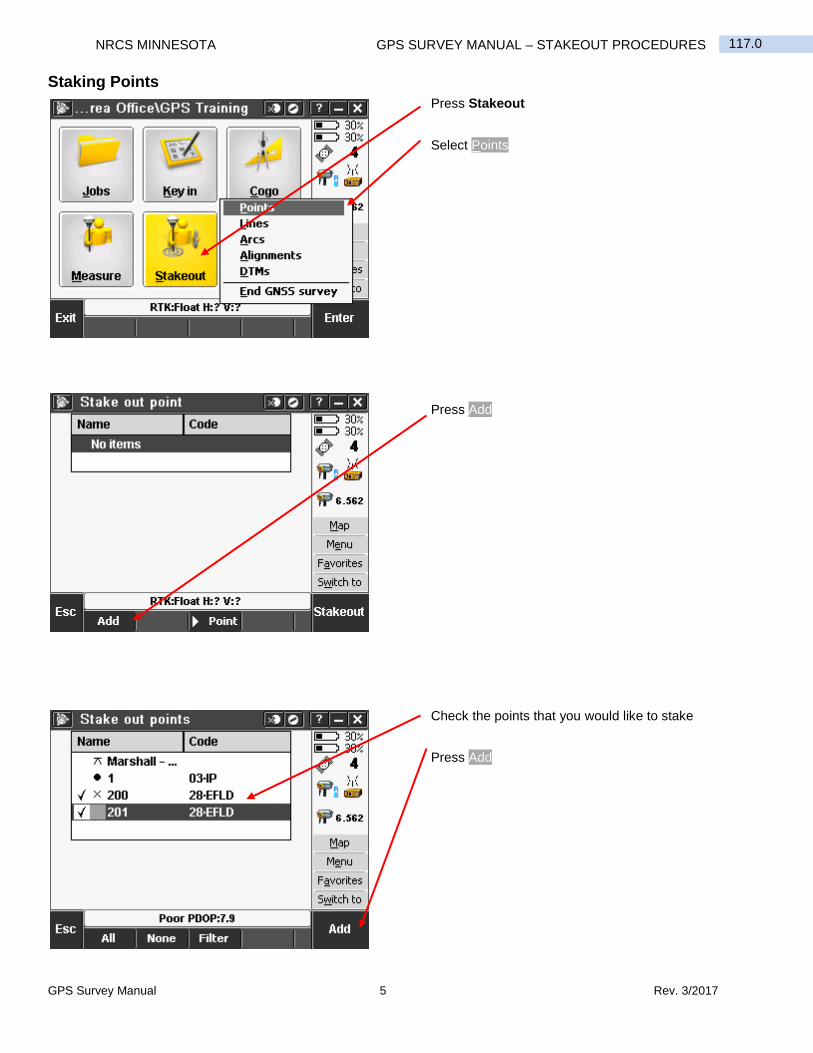
Staking Points
Press Stakeout
Select Points
Press Add
Check the points that you would like to stake
Press Add

Rev. 3/2017 6 GPS Survey Manual
GPS SURVEY MANUAL – STAKEOUT PROCEDURES NRCS MINNESOTA 117.0
Select desired point
Press Stakeout
Follow guidance to the point
Auto zoomed stakeout point screen
GPS Survey Manual 7 Rev. 3/2017
117.0 NRCS MINNESOTA GPS SURVEY MANUAL – STAKEOUT PROCEDURES
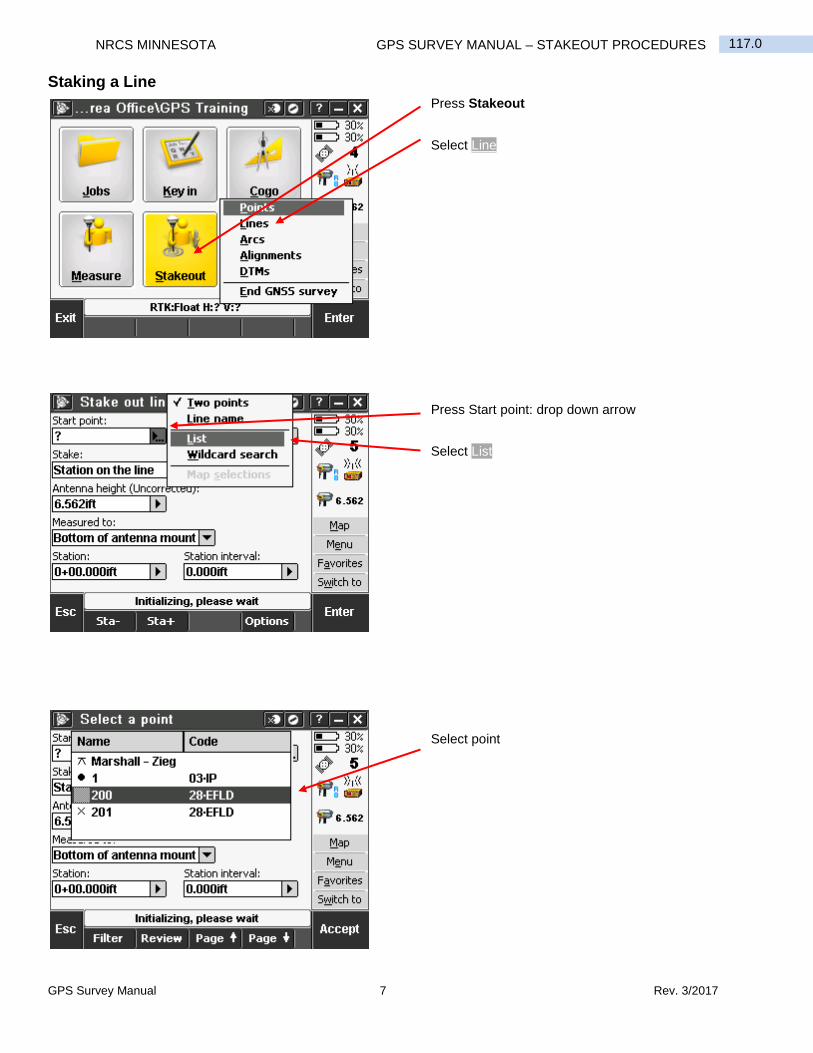
Staking a Line
Press Stakeout
Select Line
Press Start point: drop down arrow
Select List
Select point

Rev. 3/2017 8 GPS Survey Manual
GPS SURVEY MANUAL – STAKEOUT PROCEDURES NRCS MINNESOTA 117.0
Repeat previous step for End point
Press Stake: drop down arrow and select desired choice
Press Start
Stake out line

GPS Survey Manual 1 Rev. 3/2017
118.0 NRCS MINNESOTA GPS SURVEY MANUAL – METHOD FOR SETTING TRIBRACH OVER ESTABLISHED POINT
Method for Setting Tribrach Over Established Point By Cal Dunblazier 2-4-11
1. Open Tripod and extend legs
2. Keeping top level, place tripod head approximately over point.
3. Attach tribrach to tripod.
4. Step back and visually line up tripod top with point. Standing between leg “A” and leg “B” helps to visually line things up. Pivot tripod about leg “C” to adjust location.
5. Perform step 4 again standing between leg “B” and “C”. Pivot tripod about leg “A”.
6. Anchor tripod
7. Locate point using optical plummet, and move optical plummet target over point using tribrach leveling screws. (Remember the 2 and 1 rule with three leveling screws).
8. Check fish eye bubble and rough level by adjusting two legs up and/or down. You will use only two legs and always the same two legs from this point on.
9. When fish eye is rough leveled, check optical plummet, adjust optical plummet target to point if necessary following instructions listed in number 7.
10. Perform step 8 if necessary. Repeat steps 7, 8, and 9 as needed.
11. Perform fine level adjustment of fish eye bubble using tribrach leveling screws.
12. Check optical plummet and if adjustment is needed loosen tribrach and gently slide plummet target over point. This should be a minor amount.
Figure 1 RTK Base

Trimble S3 Total Station Manual 1 Rev. 3/2017
120.0 NRCS MINNESOTA TRIMBLE S3 TOTAL STATION MANUAL – BEGIN SURVEY PROCEDURES
This reference guide covers the basic set-up procedures to begin a new survey, continue with an existing survey as well as performing a resection. Please refer to the Quick Reference Guide 118.0 GPS Survey Manual – Method for Setting Tribrach Over Established Point for assistance with the physical set up of the instrument.
When you are in the main windows screen, press the Trimble Icon button on the keypad to open Access.
Press on the General Survey Module button
Press Jobs

Rev. 3/2017 2 Trimble S3 Total Station Manual
TRIMBLE S3 TOTAL STATION MANUAL – BEGIN SURVEY PROCEDURES NRCS MINNESOTA 120.0
*As long as the template field is set to “Last used job” the settings should not change. --Once the job creation is complete continue on with the survey start up.
Type in the name of the job and check the settings that you see here. Make sure the scale is set to 1.0 and that the Feature library is set to NRCS MN.
Select New Job
Then choose the VX & S Series Survey Style
Press Measure
Press Accept
Trimble S3 Total Station Manual 3 Rev. 3/2017
120.0 NRCS MINNESOTA TRIMBLE S3 TOTAL STATION MANUAL – BEGIN SURVEY PROCEDURES
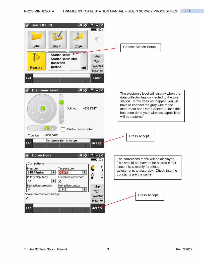
Choose Station Setup
The electronic level will display when the data collector has connected to the total station. If this does not happen you will have to connect the gray wire to the Instrument and Data Collector. Once this has been done your wireless capabilities will be restored.
Press Accept
The corrections menu will be displayed. This should not have to be altered either since this is mainly for minute adjustments to accuracy. Check that the constants are the same.
Press Accept
Rev. 3/2017 4 Trimble S3 Total Station Manual
TRIMBLE S3 TOTAL STATION MANUAL – BEGIN SURVEY PROCEDURES NRCS MINNESOTA 120.0
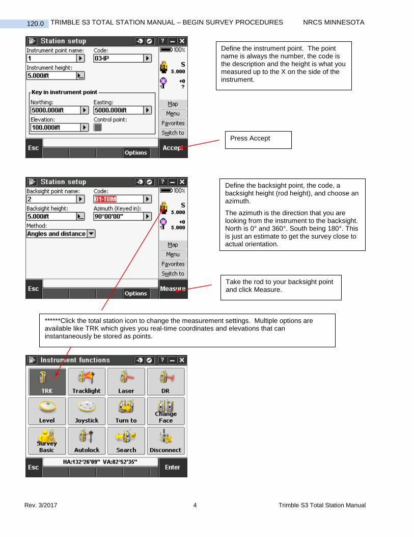
Define the instrument point. The point name is always the number, the code is the description and the height is what you measured up to the X on the side of the instrument.
Press Accept
Define the backsight point, the code, a backsight height (rod height), and choose an azimuth.
The azimuth is the direction that you are looking from the instrument to the backsight. North is 0° and 360°. South being 180°. This is just an estimate to get the survey close to actual orientation.
Take the rod to your backsight point and click Measure.
******Click the total station icon to change the measurement settings. Multiple options are available like TRK which gives you real-time coordinates and elevations that can instantaneously be stored as points.
Trimble S3 Total Station Manual 5 Rev. 3/2017
120.0 NRCS MINNESOTA TRIMBLE S3 TOTAL STATION MANUAL – BEGIN SURVEY PROCEDURES
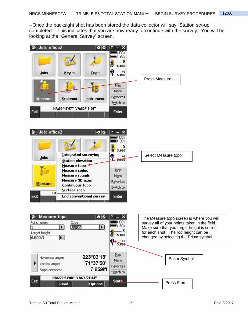
--Once the backsight shot has been stored the data collector will say “Station set-up completed”. This indicates that you are now ready to continue with the survey. You will be looking at the “General Survey” screen.
Press Measure
Select Measure topo
The Measure topo screen is where you will survey all of your points taken in the field. Make sure that you target height is correct for each shot. The rod height can be changed by selecting the Prism symbol.
Press Store
Prism Symbol
Rev. 3/2017 6 Trimble S3 Total Station Manual
TRIMBLE S3 TOTAL STATION MANUAL – BEGIN SURVEY PROCEDURES NRCS MINNESOTA 120.0
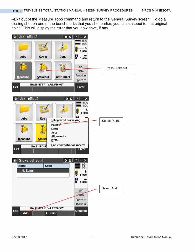
--Exit out of the Measure Topo command and return to the General Survey screen. To do a closing shot on one of the benchmarks that you shot earlier, you can stakeout to that original point. This will display the error that you now have, if any.
Select Add
Select Points
Press Stakeout
Trimble S3 Total Station Manual 7 Rev. 3/2017
120.0 NRCS MINNESOTA TRIMBLE S3 TOTAL STATION MANUAL – BEGIN SURVEY PROCEDURES
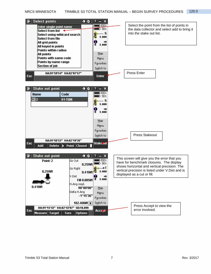
Select the point from the list of points in the data collector and select add to bring it into the stake out list.
Press Stakeout
This screen will give you the error that you have for benchmark closures. The display shows horizontal and vertical precision. The vertical precision is listed under V.Dist and is displayed as a cut or fill.
Press Accept to view the error involved.
Press Enter
Rev. 3/2017 8 Trimble S3 Total Station Manual
TRIMBLE S3 TOTAL STATION MANUAL – BEGIN SURVEY PROCEDURES NRCS MINNESOTA 120.0
--To continue with an existing survey you would also need to use the station setup method. The instrument needs to be set and leveled over a point that you have stored in the collector. You would choose this point from the list of points for your first point. The second point is your backsight and is also chosen from the list of points in the collector. Make sure the instrument and rod heights are correct before you measure the backsight.
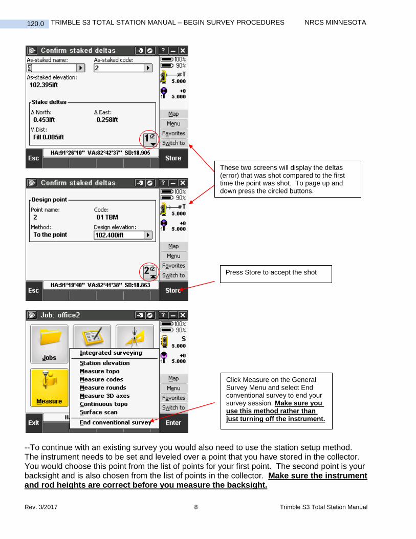
These two screens will display the deltas (error) that was shot compared to the first time the point was shot. To page up and down press the circled buttons.
Press Store to accept the shot
Click Measure on the General Survey Menu and select End conventional survey to end your survey session. Make sure you use this method rather than just turning off the instrument.
Trimble S3 Total Station Manual 9 Rev. 3/2017
120.0 NRCS MINNESOTA TRIMBLE S3 TOTAL STATION MANUAL – BEGIN SURVEY PROCEDURES
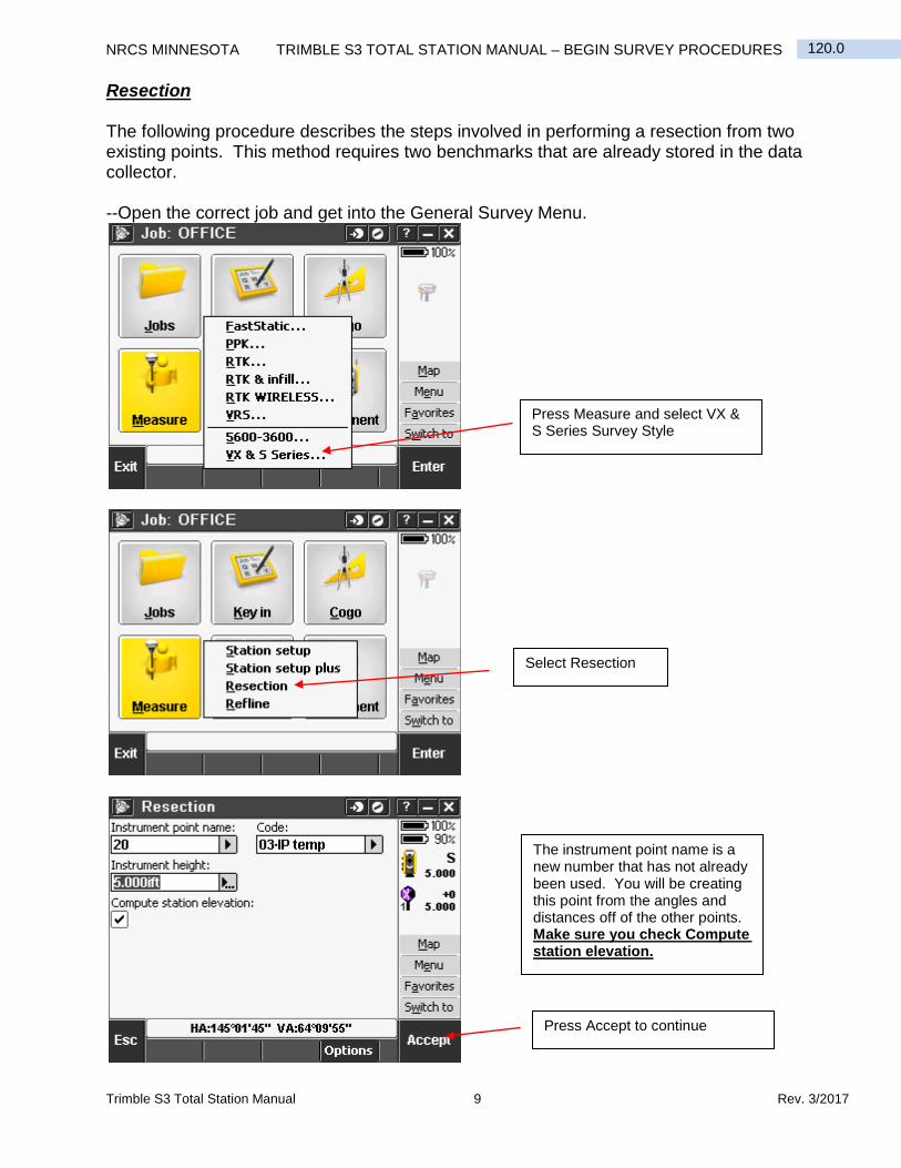
Resection The following procedure describes the steps involved in performing a resection from two existing points. This method requires two benchmarks that are already stored in the data collector. --Open the correct job and get into the General Survey Menu.
Press Measure and select VX & S Series Survey Style
Select Resection
The instrument point name is a new number that has not already been used. You will be creating this point from the angles and distances off of the other points. Make sure you check Compute station elevation.
Press Accept to continue
Rev. 3/2017 10 Trimble S3 Total Station Manual
TRIMBLE S3 TOTAL STATION MANUAL – BEGIN SURVEY PROCEDURES NRCS MINNESOTA 120.0
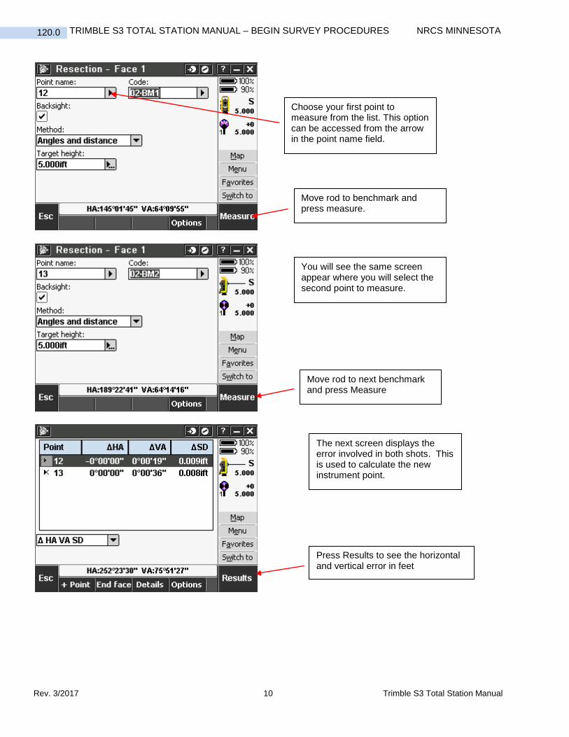
Choose your first point to measure from the list. This option can be accessed from the arrow in the point name field.
Move rod to benchmark and press measure.
You will see the same screen appear where you will select the second point to measure.
Move rod to next benchmark and press Measure
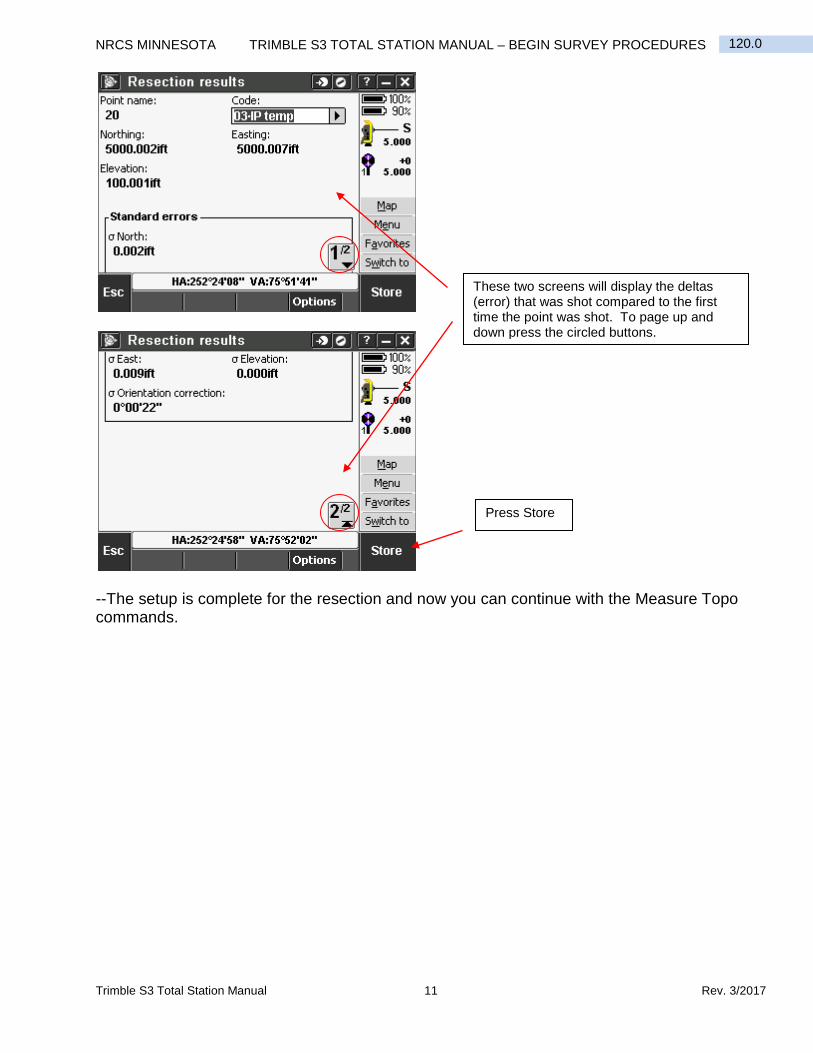
The next screen displays the error involved in both shots. This is used to calculate the new instrument point.
Press Results to see the horizontal and vertical error in feet
Trimble S3 Total Station Manual 11 Rev. 3/2017
120.0 NRCS MINNESOTA TRIMBLE S3 TOTAL STATION MANUAL – BEGIN SURVEY PROCEDURES
--The setup is complete for the resection and now you can continue with the Measure Topo commands.
These two screens will display the deltas (error) that was shot compared to the first time the point was shot. To page up and down press the circled buttons.
Press Store
Civil 3D 2016 1 Rev. 3/2017
130.0 NRCS MINNESOTA DOWNLOADING SURVEY TEXT FILE FROM TSC3 DATA COLLECTOR
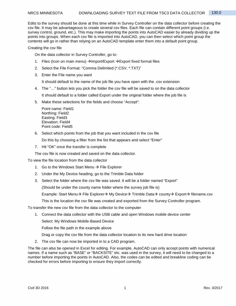
Edits to the survey should be done at this time while in Survey Controller on the data collector before creating the csv file. It may be advantageous to create several csv files. Each file can contain different point groups (i.e. survey control, ground, etc.). This may make importing the points into AutoCAD easier by already dividing up the points into groups. When each csv file is imported into AutoCAD, you can then select which point group the contents will go in rather than relying on an AutoCAD template enter them into a default point group.
Creating the csv file
On the data collector in Survey Controller, go to:
1. Files (Icon on main menu) Import/Export Export fixed format files
2. Select the File Format: “Comma Delimited (*.CSV, *.TXT)”
3. Enter the File name you want
It should default to the name of the job file you have open with the .csv extension
4. The “…” button lets you pick the folder the csv file will be saved to on the data collector
It should default to a folder called Export under the original folder where the job file is
5. Make these selections for the fields and choose “Accept”:
Point name: Field1 Northing: Field2 Easting: Field3 Elevation: Field4 Point code: Field5
6. Select which points from the job that you want included in the csv file
Do this by choosing a filter from the list that appears and select “Enter”
7. Hit “OK” once the transfer is complete
The csv file is now created and saved on the data collector.
To view the file location from the data collector
1. Go to the Windows Start Menu File Explorer
2. Under the My Device heading, go to the Trimble Data folder
3. Select the folder where the csv file was saved. It will be a folder named “Export”
(Should be under the county name folder where the survey job file is)
Example: Start Menu File Explorer My Device Trimble Data county Export filename.csv
This is the location the csv file was created and exported from the Survey Controller program.
To transfer the new csv file from the data collector to the computer
1. Connect the data collector with the USB cable and open Windows mobile device center
Select: My Windows Mobile-Based Device
Follow the file path in the example above
Drag or copy the csv file from the data collector location to its new hard drive location
2. The csv file can now be imported in to a CAD program.
The file can also be opened in Excel for editing. For example, AutoCAD can only accept points with numerical names. If a name such as “BASE” or “BACKSITE” etc. was used in the survey, it will need to be changed to a number before importing the points in AutoCAD. Also, the codes can be edited and breakline coding can be checked for errors before importing to ensure they import correctly.