Embed Size (px)
Citation preview
Researches regarding the manufacturing technology of a profiled rotor used in fluid circulation
The Romanian Review Precision Mechanics, Optics & Mechatronics, 2016, Issue 49 7
RESEARCHES REGARDING THE MANUFACTURING
TECHNOLOGY OF A PROFILED ROTOR USED IN FLUID
CIRCULATION
Lecturer Daniel Besnea, PhD Eng., As. Mihaela Constantin PhD Eng., Evelina Donisan, PhD Student Eng., Roxana
Mechno, PhD Student Eng., Prof. Nicolae Băran, PhD Eng.
Affiliation: Politehnica University of Bucharest
Post address: Splaiul Independenței nr. 313, sector 6, Bucharest
E-mail: [email protected], [email protected], [email protected],
[email protected], [email protected]
Abstract - The paper has the following objectives: The rotor constructive solution presentation, that, in
conjunction with an adjacent rotor may form a reversible machine; The manufacturing technology
development of a rotor in two versions:
I. By processing on C.N.C I;
II. By using quick prototyping (manufacturing technology with material addition).
The end of the paper presents the results obtained in version I and II.
Keywords: Profiled rotors, rotating pistons, 3D printer.
1. Introduction
To achieve results concerning new constructive
solutions to any mechanism or machine, it must be
designed, developed and built as a model in the
laboratory. The theory underlying any machines are the
results obtained on the model in the laboratory.
Using the similarity theory of the results obtained in
the laboratory, it will be applied to the "natural model",
ie the prototype.
The paper presents a rotor model which will be used
to create a prototype.
The model constructive solution is original, it can be
applied in the field of rotating machines in the following
two model versions I and II:
If note: pa - aspiration fluid pressure; pr - discharge
fluid pressure, then, two versions follows [2]:
Version I: pa> pr, as force machine:
- Steam engine;
- Pneumatic engine or hydrostatic motor.
Version II: pa <pr, as working machine:
- Pump;
- Fan;
- Low pressure compressor.
The concept of the reversible machine refers to the
fact that the same construction can be used as:
- Pump (hydrostatic motor)
- Compressor (steam engine)
There are several possibilities to build the rotor
model:
- By machining
- By working on a numerical control center (C.N.C.)
- Using quick prototyping
2. The rotor framing in a fluid circulation system
The papers [2] [3] presented a mathematical model
for calculating the rotor contour, ie specifying the
coordinates (xi, yi) in xOy orthogonal system of the
rotor profile contour.
If now, the two rotors are assembled in a case, a
fluid circulation system (fig. 1) or a metering fluid
volume system results.
The fluid is transported to the discharge and after a
90° rotation of both rotors, the situation in Figure 1. b
and thereafter in Figure 1. c is reached.
After a 180° rotation the fluid contained in the useful
volume Vu (Fig. 1. b.), ie in the space between the
pistons 3’ and 4’, will be transported to discharge.
The two rotors are identical, tangent and rotates in
reverse.
Each rotor is symmetrical to Ox and Oy axis.
In order that the rotating pistons (1) and (2) of the
upper rotor (5) to enter into the cavities (1 ') and (2') of
the lower rotor (6), a cylindrical gear was performed
outside the machine comprising two gear wheels whit
the same division diameter.
This cylindrical gear ensures a synchronous rotation
of the two rotors.
Effects of immersion duration in water on strength of instrumented composite materials
The Romanian Review Precision Mechanics, Optics & Mechatronics, 2016, Issue 49 8
a. b. c.
Figure 1. The operating principle of the volumetric meter 1, 2, 3’, 4’- rotating pistons; 1’, 2’, 3, 4- cavities in which the rotating pistons enters; 5-upper rotor; 6-
lower rotor; 7- upper case; 8- lower case; 9-upper shaft; 10-lower shaft
2. The manufacturing technology of the profiled
rotor
In this situation two constructive solution are
distinguished:
2.1. The rotor construction using a C.N.C.
2.2. The rotor construction with a manufacturing
technology with material addition.
Further, the two versions will be analyzed:
2.1. The rotor construction using a C.N.C.
CAD designing and execution CAM for numerically
controlled machines having 3 to 5-axis was performed
using the CATIA V5 software package which features a
powerful post –processing engine that allows the
coverage of the entire manufacturing process, from the
machining tool trajectory generation up to NC Code
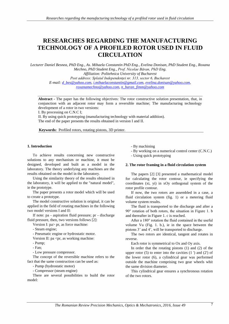
software generation [4] [5]. Based on the coordinates,
using the Sketcher mode in the Profile toolbar Point by
Using Coordinates is selected and the points are inserted
into sketch by entering the Cartesian coordinate’s
Figure 2. The rotor execution precision on C.N.C. is
0.01 mm [6].
Figure 2. The profile defining through Cartesian
coordinates and the Spline application use
The defined points are merged with the Spline toolkit
and by Transformation tool using the Symmetry
controls the full rotor profile is defined (Figure 3).
Figure 3. The rotor profile defining
The extrusion on the Z axis can be achieved using a
drawn profile (Sketcher) in closed contour and by
activating the Pad Definition command enables the
extrusion on a normal direction to the drawing plan or,
by activating the Mirrored extend option, the extrusion
can be done in both senses of the normal, figure 4.
Figure 4. The rotor three dimensional model created
with the Pad option
Effects of immersion duration in water on strength of instrumented composite materials
The Romanian Review Precision Mechanics, Optics & Mechatronics, 2016, Issue 49 9
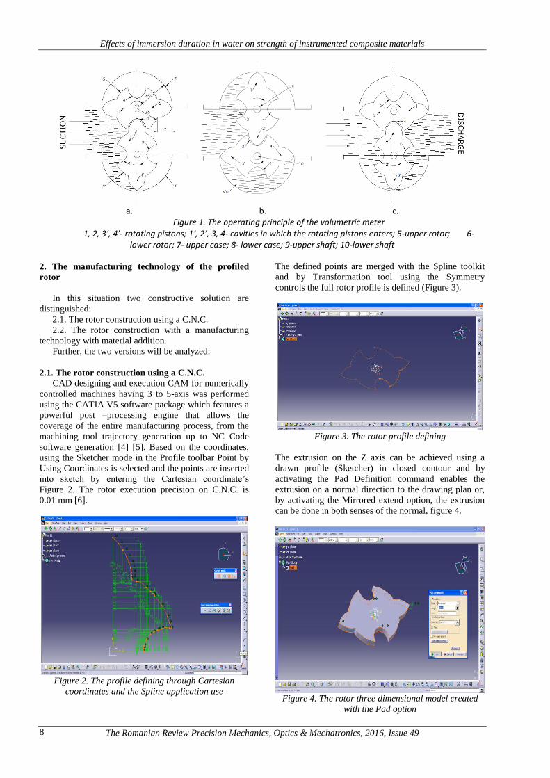
After defining the rotor geometry, the working area
opens for the NC manufacturing process in a document
CAT Product that will determine the initialization of a
new executions within the manufacturing process and
the addition of a new entity to the Operation Part
structure (Figure 4).
The access to the operation parameters can be done
through the Part Operation dialog box where the
machine tool type can be choose (Machine - editor) and
where the specific parameters of the processing machine
can be defined (numerical command parameters, the
rotation parameters, the changing tool parameters, etc.)
[7] [8].
The Axis Machine icon activates to assign a
reference axis to the processing system in operation, the
Product icon is presses to associate an existing product
to a certain operations [9] (Figure 5):
Figure 5. Selecting the processing machine depending on the axes number
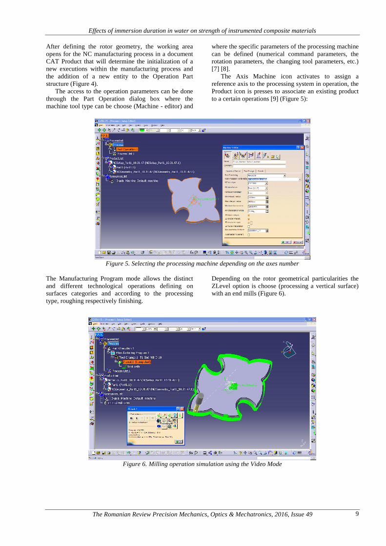
The Manufacturing Program mode allows the distinct
and different technological operations defining on
surfaces categories and according to the processing
type, roughing respectively finishing.
Depending on the rotor geometrical particularities the
ZLevel option is choose (processing a vertical surface)
with an end mills (Figure 6).
Figure 6. Milling operation simulation using the Video Mode
Effects of immersion duration in water on strength of instrumented composite materials
The Romanian Review Precision Mechanics, Optics & Mechatronics, 2016, Issue 49 10
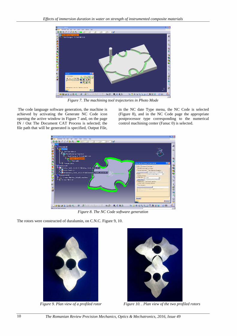
Figure 7. The machining tool trajectories in Photo Mode
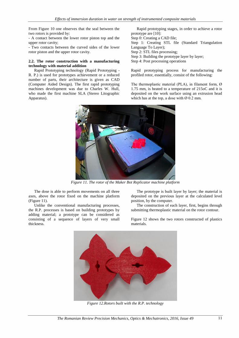
The code language software generation, the machine is
achieved by activating the Generate NC Code icon
opening the active window in Figure 7 and, on the page
IN / Out The Document CAT Process is selected; the
file path that will be generated is specified, Output File,
in the NC date Type menu, the NC Code is selected
(Figure 8), and in the NC Code page the appropriate
postprocessor type corresponding to the numerical
control machining center (Fanuc 0) is selected.
Figure 8. The NC Code software generation
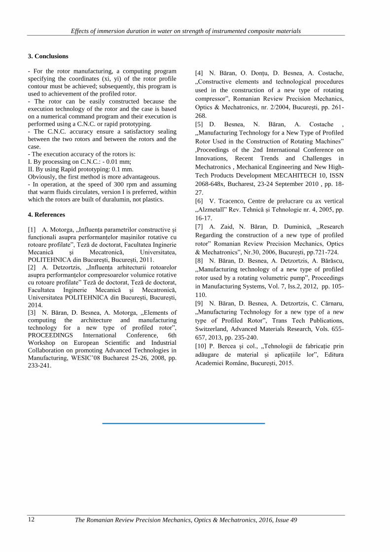
The rotors were constructed of duralumin, on C.N.C. Figure 9, 10.
Figure 9. Plan view of a profiled rotor Figure 10. . Plan view of the two profiled rotors
Effects of immersion duration in water on strength of instrumented composite materials
The Romanian Review Precision Mechanics, Optics & Mechatronics, 2016, Issue 49 11
From Figure 10 one observes that the seal between the
two rotors is provided by:
- A contact between the lower rotor piston top and the
upper rotor cavity;
- Two contacts between the curved sides of the lower
rotor piston and the upper rotor cavity.
2.2. The rotor construction with a manufacturing
technology with material addition
Rapid Prototyping technology (Rapid Prototyping -
R. P.) is used for prototypes achievement or a reduced
number of parts, their architecture is given as CAD
(Computer Aided Design). The first rapid prototyping
machines development was due to Charles W. Hull,
who made the first machine SLA (Stereo Litographic
Apparatus).
Rapid prototyping stages, in order to achieve a rotor
prototype are [10]:
Step 0: Creating a CAD file;
Step 1: Creating STL file (Standard Triangulation
Language To Layer);
Step 2: STL files processing;
Step 3: Building the prototype layer by layer;
Step 4: Post processing operations
Rapid prototyping process for manufacturing the
profiled rotor, essentially, consist of the following:
The thermoplastic material (PLA), in filament form, Ø
1.75 mm, is heated to a temperature of 215oC and it is
deposited on the work surface using an extrusion head
which has at the top, a dose with Ø 0.2 mm.
Figure 11. The rotor of the Maker Bot Replicator machine platform
The dose is able to perform movements on all three
axes, above the rotor fixed on the machine platform
(Figure 11).
Unlike the conventional manufacturing processes,
the R.P. processes is based on building prototypes by
adding material; a prototype can be considered as
consisting of a sequence of layers of very small
thickness.
The prototype is built layer by layer; the material is
deposited on the previous layer at the calculated level
position, by the computer.
The construction of each layer, first, begins through
submitting thermoplastic material on the rotor contour.
Figure 12 shows the two rotors constructed of plastics
materials.
Figure 12.Rotors built with the R.P. technology
Effects of immersion duration in water on strength of instrumented composite materials
The Romanian Review Precision Mechanics, Optics & Mechatronics, 2016, Issue 49 12
3. Conclusions
- For the rotor manufacturing, a computing program
specifying the coordinates (xi, yi) of the rotor profile
contour must be achieved; subsequently, this program is
used to achievement of the profiled rotor.
- The rotor can be easily constructed because the
execution technology of the rotor and the case is based
on a numerical command program and their execution is
performed using a C.N.C. or rapid prototyping.
- The C.N.C. accuracy ensure a satisfactory sealing
between the two rotors and between the rotors and the
case.
- The execution accuracy of the rotors is:
I. By processing on C.N.C.: - 0.01 mm;
II. By using Rapid prototyping: 0.1 mm.
Obviously, the first method is more advantageous.
- In operation, at the speed of 300 rpm and assuming
that warm fluids circulates, version I is preferred, within
which the rotors are built of duralumin, not plastics.
4. References
[1] A. Motorga, „Influența parametrilor constructive și
funcționali asupra performanțelor mașinilor rotative cu
rotoare profilate”, Teză de doctorat, Facultatea Inginerie
Mecanică și Mecatronică, Universitatea,
POLITEHNICA din București, București, 2011.
[2] A. Detzortzis, „Influența arhitecturii rotoarelor
asupra performanțelor compresoarelor volumice rotative
cu rotoare profilate” Teză de doctorat, Teză de doctorat,
Facultatea Inginerie Mecanică și Mecatronică,
Universitatea POLITEHNICA din București, București,
2014.
[3] N. Băran, D. Besnea, A. Motorga, ,,Elements of
computing the architecture and manufacturing
technology for a new type of profiled rotor”,
PROCEEDINGS International Conference, 6th
Workshop on European Scientific and Industrial
Collaboration on promoting Advanced Technologies in
Manufacturing, WESIC’08 Bucharest 25-26, 2008, pp.
233-241.
[4] N. Băran, O. Donțu, D. Besnea, A. Costache,
„Constructive elements and technological procedures
used in the construction of a new type of rotating
compressor”, Romanian Review Precision Mechanics,
Optics & Mechatronics, nr. 2/2004, București, pp. 261-
268.
[5] D. Besnea, N. Băran, A. Costache ,
,,Manufacturing Technology for a New Type of Profiled
Rotor Used in the Construction of Rotating Machines”
,Proceedings of the 2nd International Conference on
Innovations, Recent Trends and Challenges in
Mechatronics , Mechanical Engineering and New High-
Tech Products Development MECAHITECH 10, ISSN
2068-648x, Bucharest, 23-24 September 2010 , pp. 18-
27.
[6] V. Tcacenco, Centre de prelucrare cu ax vertical
„Alzmetall” Rev. Tehnică și Tehnologie nr. 4, 2005, pp.
16-17.
[7] A. Zaid, N. Băran, D. Duminică, ,,Research
Regarding the construction of a new type of profiled
rotor” Romanian Review Precision Mechanics, Optics
& Mechatronics”, Nr.30, 2006, București, pp.721-724.
[8] N. Băran, D. Besnea, A. Detzortzis, A. Bărăscu,
,,Manufacturing technology of a new type of profiled
rotor used by a rotating volumetric pump”, Proceedings
in Manufacturing Systems, Vol. 7, Iss.2, 2012, pp. 105-
110.
[9] N. Băran, D. Besnea, A. Detzortzis, C. Cărnaru,
„Manufacturing Technology for a new type of a new
type of Profiled Rotor”, Trans Tech Publications,
Switzerland, Advanced Materials Research, Vols. 655-
657, 2013, pp. 235-240.
[10] P. Bercea și col., „Tehnologii de fabricație prin
adăugare de material și aplicațiile lor”, Editura
Academiei Române, București, 2015.