Embed Size (px)
Citation preview

Research ArticleA Feeding Strategy in Inner L-Shape Ring Hot Rolling Process
WenMeng12 FeifanWang1 and Yanjin Guan2
1Key Laboratory for Advanced Materials Processing Technology Ministry of Education School of Materials Science and EngineeringTsinghua University Beijing 100084 China2Key Laboratory for Liquid-Solid Structural Evolution and Processing of Materials Ministry of EducationSchool of Materials Science and Engineering Shandong University Jinan Shandong 250061 China
Correspondence should be addressed to Yanjin Guan guan yanjinsdueducn
Received 23 March 2017 Accepted 17 July 2017 Published 19 September 2017
Academic Editor Yakov Strelniker
Copyright copy 2017 Wen Meng et al This is an open access article distributed under the Creative Commons Attribution Licensewhich permits unrestricted use distribution and reproduction in any medium provided the original work is properly cited
In order to make the inner L-shape ring polling process with a closed die structure (ILRRCDS) on the top and bottom of thedriven roll stable at first this paper established the mathematical model for ILRRCDS Then the plastic penetration and biting-inconditions for ILRRCDS were deduced based on plain ring rolling theory Moreover a feeding strategy that can realize a constantgrowth of the ringrsquos outer radius was proposed and the reasonable value ranges of the feed rate of themandrel were determinedThenumerical simulation model for ILRRCDS is established based on ABAQUS software Finally the equivalent plastic strain (PEEQ)and temperature distributions of rolled ring were obtained The results indicated that the proposed feeding strategy can realize astable ILRRCDS At the end of ILRRCDS the PEEQ at the inner radius surface of the ring ismaximum the PEEQ at the outer radiussurface of the ring takes the second place and the PEEQ at themiddle part of ring isminimumWith the increase of rolling time thehigher temperature zone of the rolled ring gradually moves from the center part of the ring to the ldquoinner corner zonerdquo of the ring
1 Introduction
The inner L-shape ring hot rolling process with a closed diestructure on the top and bottom of the driven roll (simplifiedas ILRRCDS) is an advanced plastic forming technologyto manufacture seamless inner L-shape rings It has manyadvantages in saving energy savingmaterials and decreasingnoises The rolled rings always have merits in comprehensivemechanical propertiesTherefore this ring rolling technologyis widely applied in the fields of wind power mining machin-ery and naval construction as reported by Allwood et al [1]
With the growing needs of the community for profiledrings profiled ring rolling technologies were increasinglyused to manufacture profiled rings However compared withthe ones in the rectangular ring rolling process the metalflow laws are more complicated in profiled ring rollingprocesses Recently scholars studied several profiled ringrolling processes Allwood et al [2] analyzed a profiled ringrolling process in which the mandrel can move along bothradial and axial directions and obtained the equivalent plasticstrain distribution of the rolled ring Based on ABAQUSsoftware Li et al [3] investigated the effects of forming
parameters on aluminum alloy T-shape ring rolling processand pointed out that the increase of reduction is beneficialto maintain the deformation uniformities of the rolled ringKim et al [4] studied a large-scale alloy steel profiled ringrolling process by simulationmethod based onMSC softwareand obtained the metal flow laws of the rolled ring Hua etal [5] proposed that there were three deformation behaviorsin GCr15 alloy outer L-shape cross section cold ring rollingprocess and verified them by experiments Yang et al [6]pointed out that with the increase of the reduction ratio ofthe ringrsquos wall thickness the growth of the ringrsquos radius isaccelerated during T-shape cold ring rolling processes Lee etal [7] investigated an inner L-shape ring rolling process witha profiled upper axial roll and obtained the equivalent plasticstrain and temperature distributions of the rolled ring
In the ring rolling process the feeding strategy hassignificant effects on the stability of the rolling process andon both the dimensional accuracy and the comprehensivemechanical properties of the rolled ring In recent years inorder to realize different aims scholars designed correspond-ing feeding strategies in rectangular ring rolling processesKluge et al [8] adopted a feeding strategy that could decrease
HindawiMathematical Problems in EngineeringVolume 2017 Article ID 4218289 17 pageshttpsdoiorg10115520174218289
2 Mathematical Problems in Engineering
the deformation degree of thematerials located at the cornersof the rolled ringsrsquo cross section to manufacture rectangularrings and the feeding strategy could effectively control theequivalent plastic strain and temperature distributions ofrolled Ti-6Al-4V alloy rectangular rings Guo and Yang[9] proposed a feeding strategy that could make the ringrsquosouter radius stably grow up in GH4169 steel radial-axial ringrolling process determined the reasonable value ranges of themandrel feed rate and finally verified the correctness of theproposed feeding strategy by numerical simulation methodKim et al [10] decreased themaximum load of the rollingmillby optimizing the motions of rolls in radial-axial ring rollingprocess Xu et al [11] designed an effective feeding strategyto improve the mechanical properties of rolled rectangularrings based on 42CrMo processing diagram Dish shapedrings were achieved by using the rolling strategy that causesthe ring climbing proposed by Joachim S et al (2012) Thecontrolling method of the guide rolls in double-groove ringsrolling process was studied by Tian et al [12] Li et al [13]investigated the influences of roll ratio on the inhomogeneitydeformation degree of rolled double-groove rings by usingsimulation method Giorleo et al [14] verified the hot ringrolling industrial process by Deform-3D software and theexperimental results matched the simulation ones well
To sum up scholars mainly studied the equivalent plasticstrain distribution of T-shape and L-shape rings in radial-axial ring rolling processes However studies on the feedingstrategy plastic penetration and biting-in conditions ofrolled rings controlling method of the motions of rolls andthe metal deformation laws were still insufficient
Compared with the ones in the commonly seen rectan-gular ring rolling process the metal flow laws of the innerL-shape ring in hot rolling process were more complicatedUnreasonable contacts between the guide rolls and ring maycause the instabilities in practical inner L-shape ring rollingprocess and thus themechanical properties and dimensionalaccuracy of rolled rings were worse It is hard to choose theappropriate values of mandrel feed rate Once the mandrelfeed rate was wrongly chosen there would be problems asfollows the rolled ring was blocked in the radial plastic defor-mation zone the ring was hardly bitten into the gap betweenrolls the top or bottom die of the driven roll was broken Inthis situation the further engineering applications of innerL-shape ring rolling technology would be restricted to someextentTherefore in order to solve the abovementioned prob-lems we must establish the mathematical model of the innerL-shape ring rolling process determine the plastic penetra-tion and biting-in conditions of the ring select a reasonablefeeding strategy and study the metal flow laws in ILRRCDS
2 Theoretical Calculation
Figure 1 shows the schematic diagram of ILRRCDS In therolling process the driven roll rotates around its own fixedaxis by a constant circumferential rate V119863 The mandrelmoves along the ndashX-axis direction by a set value Theringrsquos wall thickness gradually decreases while its diameterincreases
The guide rolls restrict the tilting of the ring andmaintainthe roundness of the rolled ring The axial rolls restrict thevibration of the ring and keep the rolling process stable Inthe rolling process a similar closed die structure ismade up ofthe driven roll both the top and the bottom part of the drivenroll and the mandrel This kind of die structure can restrictto some extent the metal flowing along the axial directionThus the commonly seen fishtail defects can be effectivelyprevented
ILRRCDS contains three forming stages the first formingstage the second forming stage and the roundness correctionstage The first forming stage is from the moment that themandrel starts to roll the ring to the moment that the feedamount of the mandrel just equals the step width of the L-shape ring (the step width of the L-shape ring is equal to1198771198721minus1198771198722) as shown in Figures 1(a)ndash1(c) At the first formingstage the ringrsquos upper groove is rolled out by the upper partof the mandrel119877119863 is the radius of the driven roll 1198771198721 is the upper radiusof the mandrel 1198771198722 is the lower radius of the mandrel1198671198721is the height of the upper mandrel 1198671198722 is the height of thelower mandrel119867 is the height of the initial ring blank119867 =1198671198721 + 1198671198722 120574 is the cone angle of axial roll 1198770 is the outerradius of the initial ring blank 1199030 is the inner radius of theinitial ring blank 1198771 is the outer radius of the ring at the endof the first forming stage1199031199061 is the inner radius of the upper part of the ring (UPR)at the end of the first forming stage 1199031198971 is the inner radius ofthe lower part of the ring (LPR) at the end of the first formingstage119877119905 is the instantaneous outer radius of the ring at time t119903119906119905 is the instantaneous inner radius of UPR at time t 119903119897119905 is theinstantaneous inner radius of LPR at time t Δ1198791 is the timeinterval at the first forming stage
The second forming stage is from the end of the firstforming stage to the moment that the mandrel just rightstops the feeding motion as shown in Figures 1(c)ndash1(e) Atthe second forming stage the ringrsquos wall thickness graduallydecreases while its diameter increases119877119891 is the outer radius of the ring at the end of the secondforming stage 119903119906119891 is the inner radius of UPR at the end of thesecond forming stage 119903119897119891 is the inner radius of LPR at the endof the second forming stage Δ1198792 is the time interval at thesecond forming stage
The roundness correction stage is from the end of thesecond forming stage to the moment that the mandrelcontinues rolling another two revolutions Δ1198793 is the timeinterval at the roundness correction stage
21 The Plastic Penetration and Biting-In Conditions inILRRCDS There are mainly three differences between theILRRCDS and the plain rectangular ring rolling process(simplified as PRRR) First the inner radii of UPR and LPRin ILRRCDS are different while the ring has no step in PRRRsecond the plastic penetration and biting-in conditions of theUPR are different from those of the LPR at a certain time inILRRCDS third the change laws of the growth rate of theringrsquos outer radius in ILRRCDS are different from those inPRRR
Mathematical Problems in Engineering 3
Y
X1 2 3 4
5
γ
H
RDRM1
RM2R0
r0
(1) Driven roll(2) Mandrel(3) Ring blank
(4) Upper axial roll(5) Lower axial roll
(a) 119905 = 0
Y
X
RDRM1
RM2
rut
rlt
HM1
HM2
Rt
(b) 0 lt 119905 lt Δ1198791Y
X
RDRM1
RM2R1
ru1
rl1
(c) 119905 = Δ1198791
Y
X
RDRM1
RM2Rt
rutrlt
(d) Δ1198791 lt 119905 lt Δ1198791 + Δ1198792
R
Y
X
D
RM1
RM2 Rf
ruf
rlf
(e) Δ1198791 + Δ1198792 le 119905 le Δ1198791 + Δ1198792 + Δ1198793
Figure 1 Schematic diagram of the inner L-shape ring hot rolling process
Besides the UPR is similar to the rectangular crosssection ring and so is the LPR That is to say the metalplastic flow laws at a certain horizontal plane in ILRRCDSare similar to those in PRRR Therefore it is reasonable touse the plastic penetration and biting-in conditions of therectangular ring in PRRR to analyze the plastic penetrationand biting-in conditions of the L-shape ring in ILRRCDS
This paper considered the similarity of themetal flow lawsand the differences of the cross section of the rings betweenILRRCDS and PRRR and developed the plain ring rollingtheory to analyze themetal flow laws of the ring in ILRRCDS
Figure 2 shows the metal deformation principle in ILR-RCDS In Figure 211987411198742 and1198743 are the centers of the driven
roll the mandrel and the inner L-shape ring respectively 1198711is the projected length of the contact circular arc AB betweenUPR and driven roll on 119885-axis 1198712 is the projected lengthof the contact circular arc CD between LPR and mandrelon 119885-axis Δℎ119863 Δℎ1198721 and Δℎ1198722 are the feed amount perrevolution of the driven roll the upper part of the mandreland the lower part of the mandrel respectively 11987110158401 is theprojected length of the contact circular arc 11986010158401198611015840 between theLPR and driven roll on 119885-axis 11987110158402 is the projected length ofthe contact circular arc 11986210158401198631015840 between the LPR and mandrelon 119885-axis
In Figure 2(a) according to plain ring rolling theoryreported by Hua and Zhao [16] at the first forming stage of
4 Mathematical Problems in Engineering
1
2 3
Z
X
AB
CD
EF
GH
Flow in Flow out
RD O1
L1
ΔℎD
ΔℎM1
O2L2RM1
rut
O3
Rt
(1) Driven roll(2) Mandrel(3) Ring blank
(a)
1
2 3
Z
X
Flow in Flow out
ΔℎD
ΔℎM2
RD O1
O2
RM2
O3
rltRt
L1
F
E
A
B
C
D G
H
L2
(b)
Figure 2Themetal deformation principle in ILRRCDS (a) themetal deformation principle of the UPR in the whole ILRRCDS (b) themetaldeformation principle of the LPR at the second forming stage in ILRRCDS
ILRRCDS the plastic penetration and biting-in conditions ofUPR should satisfy the following equations
Δℎmin1199061 = 000665times (119877119905 minus 119903119906119905)2 ( 1119877119863 +
11198771198721 +1119877119905 minus
1119903119906119905) (1)
Δℎmax1199061
= 21205732(1119877119863 + 11198771198721)2 (
1119877119863 +11198771198721 +
1119877119905 minus1119903119906119905)
(2)
Δℎmin1199061 le Δℎ1199061 le Δℎmax1199061 0 lt 119905 lt Δ1198791 (3)where Δℎ1199061 is the feed amount per revolution of UPR attime 119905 at the first forming stage of ILRRCDS Δℎ1199061 =Δℎ119863 + Δℎ1198721 Δℎ119863(119897 119905) and Δℎ119872(119897 119905) are the feed amountper revolution of the driven roll and the upper part of themandrel at time 119905 respectively Δℎmin1199061 and Δℎmax1199061 are thepermitted minimum and maximum of Δℎ1199061 respectively 120573is the friction angle between the inner L-shape ring and rolls120573 = arctan120583 120583 is the friction factor between the inner L-shape ring and rolls
In Figure 2(b) at the second forming stage in ILRRCDSthe plastic penetration and biting-in conditions of UPRshould satisfy the following equations
Δℎmin1199062 = 000665times (119877119905 minus 119903119906119905)2 ( 1119877119863 +
11198771198721 +1119877119905 minus
1119903119906119905) (4)
Δℎmax1199062
= 21205732(1119877119863 + 11198771198721)2 (
1119877119863 +11198771198721 +
1119877119905 minus1119903119906119905)
(5)
Δℎmin1199062 le Δℎ1199062 le Δℎmax1199062 Δ1198791 lt 119905 lt Δ1198791 + Δ1198792 (6)
where Δℎ1199062 is the feed amount per revolution of UPR at time119905 at the second forming stage in ILRRCDS Δℎ1199062 = Δℎ119863 +Δℎ1198721 Δℎmin1199062 and Δℎmax1199062 are the permitted minimum andmaximum values of Δℎ1199062 respectively
According to Hua and Zhao [16] and by assuming 1198711 =1198712 = 119871 we can obtain
Δℎ1199062 = 11987122 ( 1119877119863 +11198771198721 +
1119877119905 minus1119903119906119905) (7)
At the second forming stage in ILRRCDS the plasticpenetration andbiting-in conditions of LPR should satisfy thefollowing equations
Δℎmin1198972 = 000665times (119877119905 minus 119903119897119905)2 ( 1119877119863 +
11198771198722 +1119877119905 minus
1119903119897119905) (8)
Δℎmax1198972
= 21205732(1119877119863 + 11198771198722)2 (
1119877119863 +11198771198722 +
1119877119905 minus1119903119897119905)
(9)
Δℎmin1198972 le Δℎ1198972 le Δℎmax1198972 Δ1198791 lt 119905 lt Δ1198791 + Δ1198792 (10)
where Δℎ1198972 is the feed amount per revolution of UPR at time119905 at the second forming stage in ILRRCDS Δℎ1198972 = Δℎ119863 +Δℎ1198722 Δℎmin1198972 and Δℎmax1198972 are the permitted minimum andmaximum values of Δℎ1198972 respectively
According to [16] and by assuming 11987110158401 = 11987110158402 = 1198711015840 weobtain
Δℎ1199062 = 119871101584022 ( 1119877119863 +11198771198722 +
1119877119905 minus1119903119906119905) (11)
where Δℎ2 is named as the feed amount per revolution of thering at time 119905 at the second forming stage in ILRRCDS we get
Δℎ2 = Δℎ1199062 = Δℎ1198972 (12)
Mathematical Problems in Engineering 5
According to (6) and (10) the following equation can beobtained
Δℎ2min le Δℎ2 le Δℎ2max (13)
where Δℎ2min = maxΔℎmin1199062 Δℎmin1198972 Δℎ2max =minΔℎmax1199062 Δℎmax1198972
In conclusion the plastic penetration and biting-in con-ditions of both UPR and LPR should be satisfied simultane-ously in ILRRCDS
22 The Feeding Strategy in ILRRCDS Assuming that themandrel moved towards the driven roll by a constant ratein ILRRCDS the inner L-shape ring will grow faster In thissituation neither the guide rolls nor the axial rolls can controlthe deformation of the ring therefore the ring may vacillateand vibrate This may lead to the decrease of the mechanicalproperties and the dimensional accuracy of rolled rings
Recently Guo and Yang [9] Pan [17] and Lee and Kim[18] studied the feeding strategies in rectangular ring rollingprocesses respectively They pointed out that the feedingstrategy that can achieve a constant ringrsquos outer radius growthrate may maintain the stability of the rolling processes Leeand Kim [18] verified the feeding strategy mentioned aboveby using FE simulation and experimental methods Themandrel feeding strategy deduced by them can only be usedin radial-axial rectangular ring rolling processes but it cannotbe directly used in ILRRCDS
Therefore in order to realize a stable ILRRCDS this paperproposed a feeding strategy and deduced the reasonable valueranges of the mandrel feed rate
Theproposed feeding strategy is as follows first a suitableconstant mandrel feed rate V1198981 is adopted at the first formingstage in ILRRCDS because only the UPR is deformedsecond the feeding strategy that can achieve a constantringrsquos outer radius growth rate is adopted at the secondforming stage in ILRRCDS third the mandrel continuesrolling another two revolutions at the roundness correctionstage to make the ring round
By assuming that the outer radii of both UPR and LPRgrow up simultaneously according to the principle of volumeconstancy in ILRRCDS the ringrsquos outer radius at time 119905 canbe expressed as follows
1198771 = 1198810 + 120587 (119867119872111988721199061 + 119867119872211988721198971)2120587 [11986711987211198871199061 + 11986711987221198871198971] (14)
where1198810 is the volume of the initial ring blank1198810 = 120587(1198671198721+1198671198722)(11987720 minus 11990320) The wall thickness of LPR 119887119897119905 is constant atthe first forming stage in ILRRCDS The thickness of UPR119887119906119905 gradually decreases at the first forming stage in ILRRCDS119887119906119905 = 1198870 minus int V1198981119889119905 (0 le 119905 le Δ1198791)
At the end of the second forming stage in ILRRCDS theringrsquos outer radius can be expressed as follows
119877119891 = 1198810 + 120587 (11986711987211198872119906119891 + 11986711987221198872119897119891)2120587 [1198671198721119887119906119891 + 1198671198722119887119897119891] (15)
where 119887119906119891 is the wall thickness of the UPR at the end of thesecond forming stage in ILRRCDS 119887119906119891 = 119877119891 minus 119903119906119891 119903119906119891 is theinner radius of theUPR at the end of the second forming stagein ILRRCDS 119887119897119891 is the wall thickness of the LPR at the end ofthe second forming stage in ILRRCDS 119887119897119891 = 119877119891 minus 119903119897119891 119903119897119891 isthe inner radius of the LPR at the end of the second formingstage in ILRRCDS
On the one hand the instantaneous outer radius of thering 119877119905 can be expressed as follows
119877119905 = 1198770 + (1198771 minus 1198770) V11989811199051198771198721 minus 1198771198722 0 le 119905 lt Δ11987911198771 + V1198772119905 Δ1198791 le 119905 le Δ1198791 + Δ1198792
(16)
where V1198981 is the constant mandrel feed rate at the firstforming stage V1198772 is the constant growth rate of the ringrsquosouter radius at the second forming stage 119905 is time Δ1198791 isthe time interval of the first forming stage Δ1198791 = (1198771198721 minus1198771198722)V1198981 Δ1198792 is the time interval of the second formingstage Δ1198792 = (119877119891 minus 1198771)V1198772
On the other hand the instantaneous outer radius of thering 119877119905 can be also expressed as
119877119905 = 1198810 + 120587 [1198671198721 (119887119897119905 minus 1198771198721 + 1198771198722)2 + 11986711987221198872119897119905]2120587 [1198671198721 (119887119897119905 minus 1198771198721 + 1198771198722) + 1198671198722119887119897119905] (17)
where 119887119897119905 is the instantaneous wall thickness of LPR 119887119897119905 = 1198870minusint V119905119889119905 (Δ1198791 le 119905 le Δ1198791+Δ1198792) V119905 is the instantaneousmandrelfeed rateThe instantaneouswall thickness of UPR 119887119906119905 can becalculated by 119887119906119905 = 1198870minusint V119905119889119905minusV1198981Δ1198791 (Δ1198791 le 119905 le Δ1198791+Δ1198792)
Taking the derivative of (17) with respect to time 119905 theinstantaneous mandrel feed rate V119905 can be obtained
V119905 = 2120587 [1198671198721 (119887119897119905 minus 1198771198721 + 1198771198722) + 1198671198722119887119897119905]2119867[1198810 + 1205871198671198721 (119887119897119905 minus 1198771198721 + 1198771198722)2 + 12058711986711987221198872119897119905] minus 2120587 [1198671198721 (119887119897119905 minus 1198771198721 + 1198771198722) + 1198671198722119887119897119905]2 V1198772 (18)
23 The Reasonable Value Ranges of the Mandrel Feed RateIf we ignore the sliding motion between the rolls and ring inILRRCDS at time 119905 at the first forming stage the length ofa circle where the ringrsquos outer radius rotates is equal to the
length where the radius of the driven roll rotates Thereforewe have
2120587119877119905 = V119863Δ1199051 (1198770 le 119877119905 le 1198771 0 le 119905 lt Δ1198791) (19)
6 Mathematical Problems in Engineering
where V119863 is the peripheral velocity of the driven roll V119863 =119877119863119899119863 119899119863 is the angular velocity of the driven roll Δ1199051 is theneeded time for the ring to rotate a revolution
The feed amount per revolution of the ring can beexpressed as
Δℎ1199061 = V1198981Δ1199051 (20)
According to (3) (19) and (20) we can getV119863Δℎmin11990612120587119877119905 le V1198981 le V119863Δℎmax11990612120587119877119905 (0 le 119905 lt Δ1198791) (21)
For convenience we order 1198911(119905) = V119863Δℎmin119906121205871198771199051198921(119905) = V119863Δℎmax11990612120587119877119905 (0 le 119905 lt Δ1198791)If we ignore the sliding motion between the rolls and ring
in ILRRCDS at time 119905 at the second forming stage the lengthof a circle where the ringrsquos outer radius rotates is equal to thelength where the radius of the driven roll rotates Thereforewe have
2120587119877119905 = V119863Δ1199052 (Δ1198791 le 119905 le Δ1198791 + Δ1198792) (22)
where Δ1199052 is the time needed for the ring to rotate a circleThe feed amount per revolution of the ring can be
expressed as follows
Δℎ2 asymp V119905Δ1199052 (23)
According to (13) (22) and (23) we can obtainV119863Δℎ2min2120587119877119905 le V119905 le V119863Δℎ2max2120587119877119905
(Δ1198791 le 119905 le Δ1198791 + Δ1198792) (24)
For convenience we set 1198912(119905) = V119863Δℎ2min2120587119877119905 1198922(119905) =V119863Δℎ2max2120587119877119905 (Δ1198791 le 119905 le Δ1198791 + Δ1198792)
According to (18) (23) and (24) the reasonable valueranges of V1198772 can be expressed as follows
1198912 (119905)sdot [[119867[1198810 + 1205871198671198721 (119887119897119905 minus 1198771198721 + 1198771198722)2 + 12058711986711987221198872119897119905]
2120587 [1198671198721 (119887119897119905 minus 1198771198721 + 1198771198722) + 1198671198722119887119897119905]2
minus 1]]le V1198772 le 1198922 (119905)
sdot [[119867[1198810 + 1205871198671198721 (119887119897119905 minus 1198771198721 + 1198771198722)2 + 12058711986711987221198872119897119905]
2120587 [1198671198721 (119887119897119905 minus 1198771198721 + 1198771198722) + 1198671198722119887119897119905]2
minus 1]]
(25)
3 The FE Modeling of ILRRCDS
According to the feeding strategy established in Section 2 theFEmodel of ILRRCDSwas set up based onABAQUSExplicitsoftware as shown in Figure 3 The key FE modeling tech-niques are expressed as follows
Driven rollBack guide roll
MandrelRing blank
Upper axial rollMeasuring ball
Fore guide roll Lower axial rollRadial pass Axial pass
X
X
X
Y
ZCSYS0
CSYS1
CSYS2
Y
Y
Figure 3 FE model for ILRRCDS
Table 1 Values of coefficients in the constitutive model for S355NL[15]
Coefficients Values119876 (kJsdotmolminus1) 45010119877 (Jsdot(molsdotK)minus1) 8314119860 570 times 1015120572 0015119899 571
Table 2 Physical property parameters and values for S355NL [7]
Parameters ValuesDensity (kgm3) 7850Poissonrsquos ratio 03Youngrsquos modulus (GPa) 210Specific heat (J(kg ∘C)) 450Linear expansion coefficient (∘Cminus1) 15 times 10minus5Contact thermal conduction (W(m2 ∘C)) 10000Coefficient of thermal convection (W(m2 ∘C)) 20Thermal emissivity (Nsminus1mmminus1 ∘Cminus4) 06
31 Material Constitutive Model The material of the ringblank is S355NL (Chinese standard is Q345E) Its constitutivemodel within the forging temperature range (900∘Csim1250∘C)established by Li et al [15] is adopted that is
119885 = 120576 exp( 119876(119877119879)) = 119860 [sinh120572120590]119899 (26)
where119885 is the Zener-Hollomon parameter 120576 is the strain rate119876 is the deformation activation energy for S355NL 119877 is theuniversal gas constant 119879 is the absolute temperature 119860 is aconstant 120572 is the optimization factor of the material 119899 is theworking hardening exponent of the material The values ofthe coefficients in the above equations are shown in Table 1S355NL steelrsquos density Poissonrsquos ratio Youngrsquos modulusspecific heat linear expansion coefficient contact thermalconduction coefficient of thermal convection and thermalemissivity are listed in Table 2 as reported by Lee et al [7]
Mathematical Problems in Engineering 7
0 25 50 75 100 125 150
Rolling time (s)
100
150
200
250
300
350
Thic
knes
s of r
ing
wal
l (m
m)
butblt
(a)
0 25 50 75 100 125 150
Rolling time (s)
0
1
2
3
4
5
Man
drel
feed
rate
(mm
s)
(b)
Figure 4 (a)The changing curves of the thickness of the ring with rolling time (b) the changing curve of mandrel feed rate with rolling time
32 CAE Modeling The ring blank is defined as a three-dimensional deformable body The coupled thermodisplace-ment element with eight nodes and six faces (C3D8RT) wasadopted to mesh the ring blank according to ABAQUS 614Userrsquos Manual [19] The number of finite element meshesis approximately 10300 Reduction integration and ALEremeshing technology are also adopted to avoid the noncon-vergence of the finite element numerical solution caused byseverely distorted meshes as declared by Zhou et al [20]Hourglass control is employed to avoid zero energy modesIn order to reduce the calculated time the mass scalingtechnology and dynamic explicit algorithm are employedThe mass scaling factor is set as 50 The time scaling factoris set as 1 Six pairs of contact relationships between the ringand the rolls such as the driven roll mandrel fore guideroll back guide roll upper axial roll and lower axial rollare definedThe frictional conditions and thermal conditionssuch as thermal conduction thermal convection and thermalradiation are considered in the FE model According to theinvestigation by Shiro et al [21] the friction factor on theinterfaces between the ring and the roll can be set as 026The temperatures of all rolls are set as 200∘C The initialtemperature of blank is set as 1200∘C
33 The Motions Control of Rolls In Figure 3 the ringblank and all rolls are assembled under the global coordi-nate system CSYS0 All rolls are defined as rigid bodiesEach roll has its own reference point The rotational andtranslational motions of rolls can be controlled by settingthe motion conditions of their own corresponding referencepoints under their own coordinate system The coordinatesystem of the driven roll guide rolls and the mandrel isCSYS0 The local coordinate system of the upper axial rollis CSYS1 The local coordinate system of the lower axial rollis CSYS2 The mandrel moves along the minus119883-axis direction
The 119883 coordinate of mandrel at time 119905 119909119905 can be obtainedaccording to the equation 119909119905 = 1199090 minus int V1015840119905119889119905 where 1199090 is the119883 coordinate of mandrel at the initial time The referencepoints of guide rolls move in119883119874119885 plane while the referencepoints of axial rolls move in119883119874119884 planeThemovement locus(displacement-time relationship curves) of guide rolls andaxial rolls can be obtained from the investigation reported byPan [17]
4 Validation of the FE Model for ILRRCDS
The ILRRCDS experiments were carried out in Ireate Com-panyThematerial of ring blank is S355NLThe experimentalforming parameters are shown in Table 3 According to(21) and (25) the reasonable value ranges of V1198981 and V1198772are 076mms le V1198981 le 446mms and 253mms leV1198772 le 1491mms respectively In order to satisfy theplastic penetration and biting-in conditions of the ring inthe whole ILRRCDS we selected V1198981 = 1mms and V1198772 =10mms According to (14) and (17) the changing curves ofthe thickness of the ring with rolling time can be calculatedas shown in Figure 4(a) The height of the ring is constantin the established mathematical model for inner L-shapering hot rolling process The wall thickness of UPR 119887119906119905gradually decreases in the first and the second forming stagesThe wall thickness of LPR 119887119897119905 gradually decreases in thesecond forming stage According to (18) the changing curveof mandrel feed rate with rolling time can be calculated asshown in Figure 4(b)
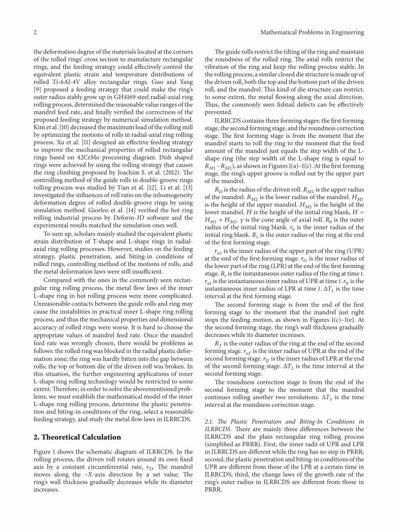
Figure 5(a) shows the rolling mill in ILRRCDS Fig-ure 5(b) shows the rolled inner L-shape ring Both the outerradius and the inner radius of the ring can bemeasured onlineby measuring roll At the end of the rolling process the tem-perature values at different positions of the rolled ring weremeasured as shown in Figure 6 Each measuring position
8 Mathematical Problems in Engineering
Table 3 Forming parameters for experimental ILRRCDS
Parameters ValuesRadius of driven roll (mm) 42500Radius of upper mandrel (mm) 27000Radius of lower mandrel (mm) 20000Height of upper mandrel (mm) 15000Height of lower mandrel (mm) 24500Radius of guide roll (mm) 30000Cone angle of axial roll (∘) 35Initial outer radius of ring (mm) 9000Initial inner radius of ring (mm) 6000Initial height of ring (mm) 3950Relative reductionlowast of UPR (mm) 131Rotational speed of driven roll (mms) 1300Temperature of all rolls (∘C) 200Temperature of ring blank (∘C) 1200Note lowastRelative reduction = ((1198770 minus 1199030) minus (119877119891 minus 119903119906119891))(119877119891 minus 119903119906119891)
Fore guide roll Mandrel
Back guide rollDriven roll Upper axial roll
Lower axial roll
Measuring roll
(a)
(b)
Figure 5 (a) Experimental ring rollingmill (b) rolled inner L-shaperings
is measured three times along the peripheral direction Thepositions of the measured points are distributed uniformlyalong the peripheral direction The average temperaturevalues at different positions of the rolled ring were calculated
Figure 7 shows the changing curves of ringrsquos inner radiusringrsquos outer radius and ringrsquos height with rolling time Itcan be seen that both ringrsquos inner and outer radii increasestably in ILRRCDS while the ringrsquos height basically staysconstant At the end of ILRRCDS the relative errors betweenthe simulation values of ringrsquos outer radius inner radiusof UPR and inner radius of LPR and experimental ones
1 2 3
4 5 6
7 8 9
Inner radiusOuter radius
Y
X
Figure 6 Temperature measuring point positions at the crosssection of the rolled ring
0 20 40 60 80 100 120
Rolling time (s)
0
500
1000
1500
2000
2500
3000
Dia
met
er an
d he
ight
of t
he ri
ng (m
m)
Rt-exp valueRt-sim valuerut-exp value
rut-sim valuerlt-exp valuerlt-sim value
Height-exp valueHeight-sim value
Figure 7The changing curves of the ringrsquos inner radius ringrsquos outerradius and ringrsquos height with rolling time
are minus185 minus241 and minus247 respectively where relativeerror is calculated by the following equation
relative error
= ((experimental value minus simulation value)experimental value
)times 100
(27)
Figure 8 shows the comparison between the experimentaltemperature values and simulative ones at different positionsof rolled ring at 119905 = 125 s It can be seen that the experimentaltemperature value at the outer surfaces of the ring at the endof the rolling process is a little lower than the simulationone The maximum relative error which locates at position7 is minus411 The reasons that caused the relative errors maybe as follows first in realistic ILRRCDS some water wasejected on the surface of the rolls in order to decrease thetemperatures of rolls and this water may increase the heatloss of the rolled ring Second it takes some time to movethe rolled ring to an appropriate position at the end ofILRRCDSbeforemeasuring the rolled ringThismay increasethe heat loss of the rolled ring because of the heat convection
Mathematical Problems in Engineering 9
0 1 2 3 4 5 6 7 8 9 10The number of selected points
0
200
400
600
800
1000
1200
Tem
pera
ture
(∘C)
Exp valueSim value
Figure 8 Comparison between the experimental temperaturevalues and simulative ones at different positions of the rolled ringat t = 125 s
and heat radiation Moreover the error can also be causedby measurement the selection of physical parameters andthe error of material constitutive model by Yang et al [22]Although there are some errors in experimental results therelative errors are lower than 5 Thus the FE model ofILRRCDS established in this paper is reliable
5 Results and Discussion
This section studied the change laws of the equivalent plasticstrain (PEEQ) and temperature distributions of rolled ringand rolling force and rolling moment with rolling time inILRRCDS The forming parameters in simulation are shownin Table 3
51 The Change Laws of the PEEQ of Rolled Ring with RollingTime At the first forming stage according to (21) when themandrel feed rate is between 076mms and 446mms theplastic penetration condition and the biting-in condition canbe simultaneously satisfied In this simulative experiment themandrel feed rate is selected as 1mmsThe total feed amountis 70mm Thus the time Δ1198791 is calculated as 700 s at thefirst forming stage According to (25) the reasonable valuerange of the growth rate of the ringrsquos outer radius is between253mms and 1491mms at the second forming stage Thegrowth rate of the ringrsquos outer radius is set as 10mms In thissituation the plastic penetration condition and the biting-in condition of the ring can be simultaneously satisfied Thetime interval of the second forming stage Δ1198792 is calculatedas 425 s At the roundness correction stage the mandrelstoppedmoving towards the driven roll and the time intervalof the roundness correction stageΔ1198793 is 125 sThus the totalrolling time is 1250 s
Figure 9 shows the PEEQ distribution of rolled ring atdifferent rolling times (PEEQ stands for the equivalent plastic
strain) As is shown in Figure 9(a) at the first forming stagethe deformations of the ring mainly locate at both the innerand the outer radius surfaces of UPR stage The value ofthe PEEQ at the inner radius surfaces of UPR is larger thanthe one at the outer radius surfaces of UPR The commonfishtail defects usually generated at the top end or bottom endsurfaces of the ring are not found In Figure 9(b) the LPRstarts to be deformed at the end of the first forming stage Andthe PEEQ at the inner radius surfaces of LPR is larger thanthe one at the outer radius surfaces of LPR The outer radiusvalue of UPR is larger than the one of LPR Besides the slightpulling and shrinking deformation of rolled ring is foundThereason may be that the metal of the UPR is rolled along theperipheral direction at the first forming stage of ILRRCDSwhile the metal of the LPR is not rolled
Figure 9(c) shows that with the increase of rolling timethe wall thickness of UPR and LPR became thinner at thesecond forming stage while the PEEQ at both the inner andthe outer surfaces of the rolled ring became larger Figure 9(d)shows that the PEEQs at both the inner and the outer surfacesof the rolled ring are larger than the one at the middle ofthe ring at the end of the rolling process which is similarto the deformation laws in radial-axial ring rolling processBesides the PEEQs at UPR are larger than the one at LPRThe minimum PEEQ locates at the middle part of LPR
Generally fishtail defects may occur at the radial plasticdeformation zone in radial-axial ring rolling process whilethis kind of defect does not occur in ILRRCDS The mainreasons can be explained from the following three aspectsfirst the closed die structure at the top and bottom of thedriven roll can effectively restrain the deformation of thering along the axial direction Second the reasonable selectedmandrel feed rate can maintain the stability of ILRRCDSThird the radial pulling and shrinking deformation is smallas declared by Han [23] The unwanted defects generated atthe first forming stage can be improved at the second formingstage
Figure 10(a) shows the initial ring blank and rolled ringSince the PEEQ and temperature distributions of the inner L-shape ring are axis-symmetric about its center a certain crosssection of rolled L-shape ring ldquoS-Srdquo is selected to study thePEEQ and temperature distributions at t = 125 s as shown inFigures 10(b) and 10(c)
In Figure 10(b) ten points (from point A to point J) wereselected to investigate the change laws of the PEEQ of therolled ring with rolling time Figure 11(a) shows the changingcurves of the PEEQs at points A-J at the cross section ldquoS-Srdquoof rolled inner L-shape ring with rolling time From Figures 9and 11(a) the PEEQs at points A C and D basically increaselinearly at first and finally keep unchanged at the roundnesscorrection stage At the end of the rolling process the PEEQsat points A C and D are 28 35 and 25 respectively
The PEEQs at points B E H and I firstly increase slowlythen increase fast and finally remain unchanged At the endof the rolling process the PEEQs at points B E H and Iare 12 15 12 and 18 respectively The reason is that thedeformations mainly locate at the inner and outer radiussurfaces of the rolled ring in the rolling processThis indicatesthat with the increase of rolling time the uniformity of the
10 Mathematical Problems in Engineering
Upper part of ring
Lower part of ring
PEEQ(avg 75)
+3837e minus 01+3521e minus 01+3206e minus 01+2890e minus 01+2574e minus 01+2258e minus 01+1942e minus 01+1626e minus 01+1311e minus 01+9948e minus 02+6789e minus 02+3631e minus 02+4723e minus 03
(a)
Outer radius Inner radius
Radial pulling and shrinking
deformation
PEEQ(avg 75)
+2876e + 00+2644e + 00+2411e + 00+2179e + 00+1946e + 00+1714e + 00+1481e + 00+1249e + 00+1017e + 00+7840e minus 01+5516e minus 01+3191e minus 01+8663e minus 02
(b)PEEQ
(avg 75)+3301e + 00+3058e + 00+2816e + 00+2573e + 00+2330e + 00+2088e + 00+1845e + 00+1602e + 00+1360e + 00+1117e + 00+8743e minus 01+6317e minus 01+3890e minus 01
(c)
PEEQ(avg 75)
+3799e + 00+3538e + 00+3277e + 00+3017e + 00+2756e + 00+2495e + 00+2234e + 00+1973e + 00+1713e + 00+1452e + 00+1191e + 00+9301e minus 01+6693e minus 01
(d)
Figure 9The equivalent plastic strain (PEEQ) distribution of the rolled ring at different rolling times (a) t = 10 s (b) t = 70 s (c) t = 90 s (d)t = 125 s
PEEQ distribution of the rolled ring became worse At theend of the rolling process the larger values of the PEEQ atthe inner radius surface of the rolled ring are 35 at point Cand 31 at point J respectively The larger PEEQs at the outerradius surface of the rolled ring locate at point A and point HThe simulative results indicate that the deformation at UPR is
larger than the one at LPR and the deformation at the innerradius surface of the rolled ring is larger than the one at theouter radius surface Besides according to ring rolling theoryreported by Hua et al [24] the feed amount per revolutionof both the upper part of the mandrel Δℎ1198721 and the lowerpart of the mandrel Δℎ1198722 is larger than the feed amount of
Mathematical Problems in Engineering 11
SS
Rolled ring
Ring blank
(a)
A CB
DE F G
H I J
799e + 00
+3
+3
538e + 00
+3277e + 00
+3017e + 00
+2756e + 00
+2495e + 00
+2234e + 00
+1973e + 00
+1713e + 00
+1452e + 00
+1191e + 00
+9301e minus 01
+6693e minus 01
PEEQ(avg 75)
(b)
A CB
DE F G
H I J
NT11
+1245e + 03
+1209e + 03
+1172e + 03
+1135e + 03
+1098e + 03
+1061e + 03
+1024e + 03
+9872e + 02
+9504e + 02
+9135e + 02
+8766e + 02
+8397e + 02
+8028e + 02
(c)Figure 10 Simulation results at the end of the rolling process (t = 125 s) (a)The initial ring blank and rolled ring (b) the PEEQ distribution atthe cross section ldquoS-Srdquo of the rolled inner L-shape ring (c) the temperature distribution at the cross section ldquoS-Srdquo of the rolled inner L-shapering (unit ∘C)
driven roll Δℎ119863 in ILRRCDS The simulative results are ingood agreement with the calculated ones
Moreover it can be seen that the PEEQ at point Fincreases fast at the first forming stage and then increasesslowly at the second forming stage At the end of the rollingprocess the PEEQ at point F is 27 This is because the metalat point F is rolled heavily and deformed seriously at the firstforming stage while the metal at UPR moved downwards atthe second forming stage which supplied sufficient metal todeform along peripheral direction at point F This decreasesthe degree of deformation of the metal at point F along theperipheral direction to some extent
It also can be seen that the metal at UPR deforms alongthe peripheral direction and ndash119884 direction from 0 s to about60 s which leads to the pulling and shrinking deformationof the ring In this situation the metal at LPR is warped anddeformed along the radial direction and thus the time atwhich the lower part of the mandrel comes into contact withthe metal at LPR (at about t = 60 s) becomes earlier than thetime predicted by the established mathematical model (at t =70 s)
Figures 11(b) and 11(c) are at t = 125 s the changing curvesof the PEEQ at the cross section ldquoS-Srdquo of rolled ring alongthe radial direction and along the axial direction respectivelyIn Figures 10(b) and 11(b) the PEEQs of both line ABC andline HIJ along the radial direction from outer radius to innerradius of the ring decrease at first and then increase ThePEEQ of line DEFG decreases at first then increases andfinally slightly decreases This is because according to plainring rolling theory the metals at both the inner and the outerradius surfaces of the ring are easier penetrated than the oneat the middle part of the ring in the rolling process
It also can be seen that the PEEQs at the UPR are largerthan the ones at both the inner and the outer radius surfacesof LPRThemain reason is that the total deformation amountof UPR is larger than the one of LPR The PEEQ at pointF is larger than the one at point G It can be deduced thatthe grain sizes at points A C D F G and J are fine due tothe larger PEEQ at these points but these positions are thepotential areas where cracks may occur due to their severedeformation
12 Mathematical Problems in Engineering
0 20 40 60 80 100 120
Rolling time (s)
0
1
2
3
4Tr
ace p
oint
PEE
Q
Point APoint BPoint C
Point EPoint FPoint G
Point HPoint IPoint J
Point D(a)
0 50 100 150 200
Distance from outer point to inner point (mm)
0
1
2
3
4
Radi
al d
istrib
utio
n PE
EQ
Line ABCLine DEFGLine HIJ
(b)
0 100 200 300 400
Distance from bottom point to top point (mm)
0
1
2
3
4
Axi
al d
istrib
utio
n PE
EQ
Line HDALine IEBLine JGFC
(c)
Figure 11 The changing curves of the PEEQ of the rolled ring (a) The changing curves of the PEEQ of points A-J with rolling time (b) thechanging curves of the PEEQ at the cross section ldquoS-Srdquo of the rolled ring along the radial direction (t = 125 s) (c) the changing curves of thePEEQ at the cross section ldquoS-Srdquo of the rolled ring along the axial direction (t = 125 s)
From Figures 10(b) and 11(c) the PEEQ of line JGFCalong the axial direction from the bottom of the ring tothe top of the ring gradually decreases and then increasesThe maximum PEEQ located at the zone near point C Theminimum PEEQ located at the zone near point GThe PEEQof line IEB gradually increases and then slightly decreasesThe maximum PEEQ located at the zone near point E Theminimum PEEQ located at the zone near point I The PEEQof line HDA gradually increases and then slightly decreasesThemaximumPEEQ located at the zone between point A andpoint D The minimum PEEQ located at the zone betweenpoint D and point H
The reason can be explained from the following twoaspects on the one hand the temperature at point A islower due to its large heat loss and thus the flow propertyof the metal at point A is worse than the one at the zonebetween point A and point D On the other hand the metaldeformation accumulation at point D is smaller
52TheChange Laws of the TemperatureDistribution of RolledRing with Rolling Time Figure 12 shows the temperaturedistributions of deforming ring at different rolling times InFigure 12(a) the temperature values at the top end surface thebottom end surface the outer radius surface and the inner
Mathematical Problems in Engineering 13
NT11+1200e + 03+1185e + 03+1169e + 03+1154e + 03+1138e + 03+1123e + 03+1108e + 03+1092e + 03+1077e + 03+1061e + 03+1046e + 03+1031e + 03+1015e + 03
(a)
NT11+1203e + 03+1170e + 03+1137e + 03+1105e + 03+1072e + 03+1039e + 03+1007e + 03+9740e + 02+9414e + 02+9087e + 02+8761e + 02+8435e + 02+8108e + 02
(b)
Inner corner zone
NT11+1225e + 03+1190e + 03+1155e + 03+1120e + 03+1085e + 03+1050e + 03+1015e + 03+9798e + 02+9448e + 02+9098e + 02+8747e + 02+8397e + 02+8047e + 02
(c)
Inner corner zone
Central part of ring
Upper end surface
NT11+1245e + 03+1209e + 03+1172e + 03+1135e + 03+1098e + 03+1061e + 03+1024e + 03+9872e + 02+9504e + 02+9135e + 02+8766e + 02+8397e + 02+8028e + 02
(d)
Figure 12 The temperature distributions of deforming ring at different rolling times (a) t = 10 s (b) t = 70 s (c) t = 90 s (d) t = 125 s (unit∘C)
radius surface of UPR are larger due to the large heat losscaused by the heat conduction between the ring and rollssuch as the driven roll axial rolls and the upper part of themandrel The temperature value at the inner radius surfaceof LPR is small because the heat loss at the inner radiussurface of LPR is small Figure 12(b) shows the temperaturedistribution of deforming ring at the end of the first formingstage In Figure 12(b) the temperature at the surfaces of thering is smaller than the one at the center of the ring The
temperatures at the top end surface and the bottom endsurface of the ring are smaller than those at other positionsThe reason is that on the one hand the heat conductionbetween the ring and the rolls such as the driven roll axialrolls and the upper part of the mandrel leads to moreheat loss On the other hand the heat convection and heatradiation between the ringrsquos surfaces and the air also causeheat loss Figure 12(c) shows the temperature distributionof deforming ring at t = 90 s The high temperature zone
14 Mathematical Problems in Engineering
gradually moves form the center part of the ring to the ldquoinnercorner zonerdquo of the L-shape ring Figure 12(d) shows thetemperature distribution of deforming ring at t = 125 s Themaximum temperature zone is near the ldquoinner corner zonerdquoof the L-shape ring
Generally the temperature distribution of the rolled ringis axis-symmetric about its center in the rectangular radial-axial ring rolling process The temperatures at both the outerand the inner radius surfaces of the ring are lower thanthe one at the center part of the ring However the hightemperature zone moves to the ldquoinner corner zonerdquo in theinner L-shape ring rolling process The main reason is asfollows first the deformation of the ring is asymmetric Thedeformation of UPR is larger than the deformation of LPRAnd thus the uniformity of the distribution of heat generatedby metal deformation becomes worse Second the contactarea between the LPR and the lower part of the mandrel islarge The contact time between the LPR and the lower partof the mandrel is too long In this situation the heat loss ofUPR is larger than the one of LPRThird the specific surfacearea at the ldquoinner corner zonerdquo of the ring is small whichis the disadvantage of heat convection and heat radiationOn the contrary the heat loss at other zones caused by heatconvection and heat radiation is large due to their largespecific surface area
In Figure 10(b) ten points (from point A to point J) wereselected to investigate the change laws of the temperatureof the rolled ring with rolling time Figure 13(a) showsthe changing curves of the temperature values at pointsA-J with rolling time The temperatures at points D E Fand G positions are basically above 1140∘C in the wholeILRRCDS However the temperatures at other positionsgradually decrease with rolling time The temperatures atpoints A to J positions are above 830∘C at the end of therolling process The temperature at point G decreases atfirst then increases and finally keeps unchanged Its finaltemperature is 1180∘C This may be because the heat loss atpoint G is too large at the first forming stage and the heatgenerated by metal deformation at point G is larger than theheat loss at point G at the second forming stage Thus thetemperature at point G slightly increases The temperaturesat points B H and I positions gradually decrease at the firstforming stage slightly increase at the second forming stageand finally decrease The final temperatures at points B Hand I positions are 880∘C 920∘C and 960∘C respectivelyThe reason may be that the generated heat at these positionsfrom 70 s to 90 s is larger than the heat loss at these positionsbut the generated heat at these positions from 90 s to 125 s issmaller than the heat loss at these positions Moreover thetemperatures at points A B C and H positions are 830∘C880∘C 925∘C and 920∘C respectively The temperatures atpoints A B C and H positions are smaller than the onesat other positions due to the larger heat loss and smallergenerated heat at these positions
Figures 13(b) and 13(c) show at t = 125 s the changingcurves of the temperature of the rolled ring along the radialdirection and the axial direction respectively From Figures10(c) and 13(b) the temperatures at line ABC and lineHIJ along the radial direction from the ringrsquos inner radius
to the ringrsquos outer radius both increase at first and thenslightly decrease The temperatures at line DEFG increase atfirst then decrease and finally increase slightly Besides thetemperatures at the middle of the ring at the bottom endsurface and at the top end surface decrease systematically InFigures 10(c) and 13(c) the temperatures at line JGFC and lineHDA along the axial direction from the bottom end surfaceof the ring to the top end surface of the ring both graduallyincrease at first and then decrease The temperatures atline IEB increase firstly then keep unchanged and finallydecrease
From Figures 10(c) 13(b) and 13(c) it can be seen thatthe temperature at the center part of the ring is larger thanthe ones at the surfaces of the ring The difference betweenthe temperatures at the surfaces of the ring and the one atthe corner zone is large The temperatures at points A C Hand J positions are lower This may be explained from thefollowing two aspects on the one hand the heat loss at thesepoints is larger due to the larger heat conduction betweenthe ring and the rolls On the other hand the specific surfaceareas at points A C H and J positions are large and thusthe heat loss is large The temperatures at points A C and Hpositions are lower than the temperature at point J positionThe reason may be that first the heat losses at points A CandHpositions are larger than the heat loss at point J positionbecause there is heat conduction between the UPR with thedriven roll and the upper part of the mandrel Second theheat generated by metal deformation at point H position islower than the one generated by metal deformation at pointJ position because the metal at point J position deformsfrom about 60 s to 112 s while the metal at point H positiondeforms from about 70 s to 112 s Third according to the ringrolling theory the feed amount per revolution of mandrelis larger than the one of driven roll which leads to largermetal deformation amount and larger generated heat at pointJ position
In Figure 13(b) the change lawof rolled ringrsquos temperaturealong line DEF is similar to the one along line ABCThemainreason is that the total feed amount of the ring at line DEF isequal to the one at line ABC The change law of rolled ringrsquostemperature along line FG is slightly different from that alongline IJ The main reason is that the total feed amount of thering at line FG is equal to the one at line IJ but the heat lossat point G position is smaller than the one at point J positionIt can be deduced that the metal at line FG may be destroyedbecause the metal at the position suffers residual hot tensilestress
53 The Change Laws of Rolling Force and Rolling Momentwith Rolling Time Figure 14 shows the changing curve ofrolling force with rolling time The rolling forces of boththe driven roll and the mandrel gradually increase at thefirst forming stage The rolling forces of both the driven rolland the mandrel seriously increase at first and then keepunchanged at the second forming stage The rolling forces ofboth the driven roll and the mandrel gradually decrease atthe roundness correction stage In the whole ILRRCDS therolling force of the mandrel is maximum the rolling force of
Mathematical Problems in Engineering 15
0 20 40 60 80 100 120
Rolling time (s)
800
900
1000
1100
1200
Trac
e poi
nt te
mpe
ratu
re (∘
C)
Point APoint BPoint C
Point EPoint FPoint G
Point HPoint IPoint J
Point D(a)
800
900
1000
1100
1200
0 50 100 150 200
Distance from outer point to inner point (mm)
Radi
al d
istrib
utio
n te
mpe
ratu
re (∘
C)
Line ABCLine DEFGLine HIJ
(b)
800
900
1000
1100
1200
0 100 200 300 400
Distance from bottom point to top point (mm)
Axi
al d
istrib
utio
n te
mpe
ratu
re (∘
C)
Line HDALine IEBLine JGFC
(c)
Figure 13 The changing of the temperature of the rolled ring (a) The changing curves of the temperature of points A-J with rolling time(b) the changing curves of the temperature along the radial direction (t = 125 s) (c) the changing curves of the temperature along the axialdirection (t = 125 s)
the driven roll takes the second place and the rolling force ofthe axial rolls is minimum
When the rolling time is around 20 s the rolling force ofthe upper axial roll exists but the rolling force of the loweraxial roll is zero This indicates that a warped deformationalong the 119884-axis may occur in the axial plastic deformationzone When the rolling time is around 50 s 70 s 1175 s and125 s the rolling force of the lower axial roll exists but therolling force of the upper axial roll is zero This indicates thata warped deformation along the minus119884-axis directionmay occurin the axial plastic deformation zone When the rolling timeis around 60 s and 100 s the rolling forces of both the upperaxial roll and the lower axial roll existThismay be because the
pulling and shrinking deformation along the radial directionin the rolling process leads to warped deformations along the119884-axis at the inner radius surface of the ring and along theminus119884-axis at the outer radius surface of the ring
Figure 15 shows the changing curve of rolling momentwith rolling time The change laws of rolling moment withrolling time are similar to the change laws of rolling forcewithrolling time In the whole ILRRCDS the rolling moment ofthe mandrel is maximum the rolling moment of the drivenroll takes the second place and the rolling moment of axialrolls is minimum The metal deformation of the ring alongthe axial direction is seriously restricted by the closed diestructure of the top and bottom of the driven roll
16 Mathematical Problems in Engineering
0 20 40 60 80 100 120
Rolling time (s)
0
500
1000
1500
2000
Rolli
ng fo
rce (
kN)
Driven rollMandrel
Upper axial rollLower axial roll
Figure 14 The changing curve of rolling force with rolling time
0 20 40 60 80 100 120
Rolling time (s)
0
100
200
300
400
500
Rolli
ng m
omen
t (kN
middotm)
Driven rollMandrel
Upper axial rollLower axial roll
Figure 15The changing curve of rolling moment with rolling time
6 Conclusions
This paper established themathematicalmodel for ILRRCDSdeduced the plastic penetration and biting-in conditions ofthe ring in ILRRCDS proposed a feeding strategy that canrealize a constant growth for the ringrsquos outer radius anddetermined the reasonable value ranges of the feed rate ofthe mandrel Finally both the PEEQ and the temperaturedistributions of rolled ring and the change laws of the rollingforce and rolling moment with rolling time were obtainedThe main conclusions are drawn as follows
(1) The plastic penetration and biting-in conditions ofthe UPR should satisfy Δℎmin1199061 le Δℎ1199061 le Δℎmax1199061at the first forming stage the plastic penetration andbiting-in conditions of both the UPR and the LPR at
the second forming stage should satisfy the followingformulae
Δℎ2min = max Δℎmin1199062 Δℎmin1198972 Δℎ2max = min Δℎmax1199062 Δℎmax1198972
Δℎ2min le Δℎ2 le Δℎ2max(28)
The reasonable value ranges of V1198772 should satisfy thefollowing formula
1198912 (119905)sdot [[119867[1198810 + 1205871198671198721 (119887119897119905 minus 1198771198721 + 1198771198722)2 + 12058711986711987221198872119897119905]
2120587 [1198671198721 (119887119897119905 minus 1198771198721 + 1198771198722) + 1198671198722119887119897119905]2
minus 1]]le V1198772 le 1198922 (119905)
sdot [[119867[1198810 + 1205871198671198721 (119887119897119905 minus 1198771198721 + 1198771198722)2 + 12058711986711987221198872119897119905]
2120587 [1198671198721 (119887119897119905 minus 1198771198721 + 1198771198722) + 1198671198722119887119897119905]2
minus 1]]
(29)
(2) The proposed feeding strategy can realize a stableILRRCDS And simulative results indicate that thepulling and shrinking deformations occurred at LPRat the first forming stage in ILRRCDS while thesedeformations were improved at the second formingstage At the end of ILRRCDS the PEEQ at the innerradius surface of the rolled ring is maximum thePEEQ at the outer radius surface of the rolled ringtakes the second place and the PEEQ at the middlepart of the rolled ring is minimum
(3) The differences between the temperature at the centerpart of the rolled ring and those at the surface of thering are great The temperature at the center part ofthe rolled ring at the first forming stage is higher thanthe one at the surface of the rolled ring The highertemperature zone gradually moves from the centerpart of the rolled ring to the ldquoinner corner zonerdquo ofthe rolled ring At the end of the rolling process thetemperatures at the middle of the rolled ring at thebottom end surface of the rolled ring and at the topend surface of the rolled ring decreased in turn
(4) The rolling forces and rolling moments of both thedriven roll and the mandrel gradually increase atthe first forming stage The rolling forces and rollingmoments of both the driven roll and the mandrelseriously increase at first and then keep unchangedat the second forming stage The rolling forces androlling moments of both the driven roll and the man-drel gradually decrease at the roundness correctionstage In the whole ILRRCDS the rolling force and
Mathematical Problems in Engineering 17
rolling moment of the mandrel are maximum therolling force and rolling moment of the driven rolltake the second place and the rolling force and rollingmoment of the axial rolls are minimum
Conflicts of Interest
The authors declare that there are no conflicts of interestregarding the publication of this paper
References
[1] J M Allwood A E Tekkaya and T F Stanistreet ldquoThe devel-opment of ring rolling technologyrdquo Steel Research Internationalvol 76 no 2-3 pp 111ndash120 2005
[2] J M Allwood R Kopp D Michels et al ldquoThe technical andcommercial potential of an incremental ring rolling processrdquoCIRPAnnals -Manufacturing Technology vol 54 no 1 pp 233ndash236 2005
[3] L Li H Yang L Go and Z Sun ldquoResearch on interactiveinfluences of parameters on T-shaped cold ring rolling by 3d-FE numerical simulationrdquo Journal of Mechanical Science andTechnology vol 21 no 10 pp 1541ndash1547 2007
[4] K H Kim H G Suk and M Y Huh ldquoDevelopment of theprofile ring rolling process for large slewing rings of alloy steelsrdquoJournal ofMaterials Processing Technology vol 187-188 pp 730ndash733 2007
[5] L Hua D-S Qian and L-B Pan ldquoDeformation behaviors andconditions in L-section profile cold ring rollingrdquo Journal ofMaterials Processing Technology vol 209 no 11 pp 5087ndash50962009
[6] H Yang L Li M Wang and L Guo ldquoResearch on theexpanding deformation of ring radius in cold profiled ringrolling processrdquo ScienceChinaTechnological Sciences vol 53 no3 pp 813ndash821 2010
[7] Y S Lee M W Lee S S Park I Lee and Y H Moon ldquoProcessdesign by FEM simulation for shape ring rolling of large-sizedringrdquo in Proceedings of the 10th International Conference onNumerical Methods in Industrial Forming Processes Dedicated toProfessor O C Zienkiewicz (1921-2009) NUMIFORM 2010 pp964ndash971 kor June 2010
[8] A Kluge Y-H Lee H Wiegels and R Kopp ldquoControl ofstrain and temperature distribution in the ring rolling processrdquoJournal of Materials Processing Tech vol 45 no 1-4 pp 137ndash1411994
[9] L Guo and H Yang ldquoTowards a steady forming condition forradial-axial ring rollingrdquo International Journal of MechanicalSciences vol 53 no 4 pp 286ndash299 2011
[10] N Kim H Kim and K Jin ldquoOptimal design to reduce themaximum load in ring rolling processrdquo International Journalof Precision Engineering and Manufacturing vol 13 no 10 pp1821ndash1828 2012
[11] W Xu X Yang Z Jiang and QWang ldquoFeeding strategy designfor steel 42CrMo in radial-axial ring rolling using processingmaprdquo International Journal of Material Forming pp 1ndash8 2013
[12] L Tian Y Luo H-J Mao and L Hua ldquoA hybrid of theoryand numerical simulation research for virtual rolling of double-groove ball ringsrdquo International Journal of Advanced Manufac-turing Technology vol 69 no 1-4 pp 1ndash13 2013
[13] L Li X Li J Liu and Z He ldquoModeling and simulationof cold rolling process for double groove ball-section ringrdquo
International Journal of Advanced Manufacturing Technologyvol 69 no 5-8 pp 1717ndash1729 2013
[14] L Giorleo C Giardini and E Ceretti ldquoValidation of hot ringrolling industrial process 3D simulationrdquo International Journalof Material Forming vol 6 no 1 pp 145ndash152 2013
[15] J Li X Zhang and J Liu ldquoHot deformation behavior anddynamic Recrystallization diagram for low-alloy Q345E steel athigh temperaturerdquo J Forgingamp Stamping Technology vol 38 pp148ndash151 2013
[16] L Hua and Z Z Zhao ldquoThe extremum parameters in ringrollingrdquo Journal of Materials Processing Technology vol 69 no1-3 pp 273ndash276 1997
[17] L B PanOn deformation laws and CAPP system for radial-axialring rolling [Doctoral thesis] Doctoral Dissertation for WuhanUniversity of Technology Wuhan 2007
[18] K-H Lee andB-MKim ldquoAdvanced feasible forming conditionfor reducing ring spreads in radial-axial ring rollingrdquo Interna-tional Journal of Mechanical Sciences vol 76 pp 21ndash32 2013
[19] ldquoABAQUS 614 Userrsquos Manual 2014rdquo[20] G Zhou L Hua J Lan and D S Qian ldquoFE analysis of coupled
thermo-mechanical behaviors in radial-axial rolling of alloysteel large ringrdquo Computational Materials Science vol 50 no1 pp 65ndash76 2010
[21] K Shiro O Soo-ik and A TaylanMetal Forming and the FiniteElement Method Oxiford University Press New York USA1989
[22] H Yang M Wang L G Guo and Z C Sun ldquo3D coupledthermo-mechanical FE modeling of blank size effects on theuniformity of strain and temperature distributions during hotrolling of titanium alloy large ringsrdquo Computational MaterialsScience vol 44 no 2 pp 611ndash621 2008
[23] X H HanThe investigation of rolling technology and equipmentin conical ring rolling with inner steps Mastersrsquo Dissertation forWuhan University of Technology Wuhan China 2006
[24] L Hua X G Huang and C D Zhu Theory and Technology ofRing Rolling Mechanical Industry Press Beijing China 2001
Submit your manuscripts athttpswwwhindawicom
Hindawi Publishing Corporationhttpwwwhindawicom Volume 2014
MathematicsJournal of
Hindawi Publishing Corporationhttpwwwhindawicom Volume 2014
Mathematical Problems in Engineering
Hindawi Publishing Corporationhttpwwwhindawicom
Differential EquationsInternational Journal of
Volume 2014
Applied MathematicsJournal of
Hindawi Publishing Corporationhttpwwwhindawicom Volume 2014
Probability and StatisticsHindawi Publishing Corporationhttpwwwhindawicom Volume 2014
Journal of
Hindawi Publishing Corporationhttpwwwhindawicom Volume 2014
Mathematical PhysicsAdvances in
Complex AnalysisJournal of
Hindawi Publishing Corporationhttpwwwhindawicom Volume 2014
OptimizationJournal of
Hindawi Publishing Corporationhttpwwwhindawicom Volume 2014
CombinatoricsHindawi Publishing Corporationhttpwwwhindawicom Volume 2014
International Journal of
Hindawi Publishing Corporationhttpwwwhindawicom Volume 2014
Operations ResearchAdvances in
Journal of
Hindawi Publishing Corporationhttpwwwhindawicom Volume 2014
Function Spaces
Abstract and Applied AnalysisHindawi Publishing Corporationhttpwwwhindawicom Volume 2014
International Journal of Mathematics and Mathematical Sciences
Hindawi Publishing Corporationhttpwwwhindawicom Volume 201
The Scientific World JournalHindawi Publishing Corporation httpwwwhindawicom Volume 2014
Hindawi Publishing Corporationhttpwwwhindawicom Volume 2014
Algebra
Discrete Dynamics in Nature and Society
Hindawi Publishing Corporationhttpwwwhindawicom Volume 2014
Hindawi Publishing Corporationhttpwwwhindawicom Volume 2014
Decision SciencesAdvances in
Journal of
Hindawi Publishing Corporationhttpwwwhindawicom
Volume 2014 Hindawi Publishing Corporationhttpwwwhindawicom Volume 2014
Stochastic AnalysisInternational Journal of
2 Mathematical Problems in Engineering
the deformation degree of thematerials located at the cornersof the rolled ringsrsquo cross section to manufacture rectangularrings and the feeding strategy could effectively control theequivalent plastic strain and temperature distributions ofrolled Ti-6Al-4V alloy rectangular rings Guo and Yang[9] proposed a feeding strategy that could make the ringrsquosouter radius stably grow up in GH4169 steel radial-axial ringrolling process determined the reasonable value ranges of themandrel feed rate and finally verified the correctness of theproposed feeding strategy by numerical simulation methodKim et al [10] decreased themaximum load of the rollingmillby optimizing the motions of rolls in radial-axial ring rollingprocess Xu et al [11] designed an effective feeding strategyto improve the mechanical properties of rolled rectangularrings based on 42CrMo processing diagram Dish shapedrings were achieved by using the rolling strategy that causesthe ring climbing proposed by Joachim S et al (2012) Thecontrolling method of the guide rolls in double-groove ringsrolling process was studied by Tian et al [12] Li et al [13]investigated the influences of roll ratio on the inhomogeneitydeformation degree of rolled double-groove rings by usingsimulation method Giorleo et al [14] verified the hot ringrolling industrial process by Deform-3D software and theexperimental results matched the simulation ones well
To sum up scholars mainly studied the equivalent plasticstrain distribution of T-shape and L-shape rings in radial-axial ring rolling processes However studies on the feedingstrategy plastic penetration and biting-in conditions ofrolled rings controlling method of the motions of rolls andthe metal deformation laws were still insufficient
Compared with the ones in the commonly seen rectan-gular ring rolling process the metal flow laws of the innerL-shape ring in hot rolling process were more complicatedUnreasonable contacts between the guide rolls and ring maycause the instabilities in practical inner L-shape ring rollingprocess and thus themechanical properties and dimensionalaccuracy of rolled rings were worse It is hard to choose theappropriate values of mandrel feed rate Once the mandrelfeed rate was wrongly chosen there would be problems asfollows the rolled ring was blocked in the radial plastic defor-mation zone the ring was hardly bitten into the gap betweenrolls the top or bottom die of the driven roll was broken Inthis situation the further engineering applications of innerL-shape ring rolling technology would be restricted to someextentTherefore in order to solve the abovementioned prob-lems we must establish the mathematical model of the innerL-shape ring rolling process determine the plastic penetra-tion and biting-in conditions of the ring select a reasonablefeeding strategy and study the metal flow laws in ILRRCDS
2 Theoretical Calculation
Figure 1 shows the schematic diagram of ILRRCDS In therolling process the driven roll rotates around its own fixedaxis by a constant circumferential rate V119863 The mandrelmoves along the ndashX-axis direction by a set value Theringrsquos wall thickness gradually decreases while its diameterincreases
The guide rolls restrict the tilting of the ring andmaintainthe roundness of the rolled ring The axial rolls restrict thevibration of the ring and keep the rolling process stable Inthe rolling process a similar closed die structure ismade up ofthe driven roll both the top and the bottom part of the drivenroll and the mandrel This kind of die structure can restrictto some extent the metal flowing along the axial directionThus the commonly seen fishtail defects can be effectivelyprevented
ILRRCDS contains three forming stages the first formingstage the second forming stage and the roundness correctionstage The first forming stage is from the moment that themandrel starts to roll the ring to the moment that the feedamount of the mandrel just equals the step width of the L-shape ring (the step width of the L-shape ring is equal to1198771198721minus1198771198722) as shown in Figures 1(a)ndash1(c) At the first formingstage the ringrsquos upper groove is rolled out by the upper partof the mandrel119877119863 is the radius of the driven roll 1198771198721 is the upper radiusof the mandrel 1198771198722 is the lower radius of the mandrel1198671198721is the height of the upper mandrel 1198671198722 is the height of thelower mandrel119867 is the height of the initial ring blank119867 =1198671198721 + 1198671198722 120574 is the cone angle of axial roll 1198770 is the outerradius of the initial ring blank 1199030 is the inner radius of theinitial ring blank 1198771 is the outer radius of the ring at the endof the first forming stage1199031199061 is the inner radius of the upper part of the ring (UPR)at the end of the first forming stage 1199031198971 is the inner radius ofthe lower part of the ring (LPR) at the end of the first formingstage119877119905 is the instantaneous outer radius of the ring at time t119903119906119905 is the instantaneous inner radius of UPR at time t 119903119897119905 is theinstantaneous inner radius of LPR at time t Δ1198791 is the timeinterval at the first forming stage
The second forming stage is from the end of the firstforming stage to the moment that the mandrel just rightstops the feeding motion as shown in Figures 1(c)ndash1(e) Atthe second forming stage the ringrsquos wall thickness graduallydecreases while its diameter increases119877119891 is the outer radius of the ring at the end of the secondforming stage 119903119906119891 is the inner radius of UPR at the end of thesecond forming stage 119903119897119891 is the inner radius of LPR at the endof the second forming stage Δ1198792 is the time interval at thesecond forming stage
The roundness correction stage is from the end of thesecond forming stage to the moment that the mandrelcontinues rolling another two revolutions Δ1198793 is the timeinterval at the roundness correction stage
21 The Plastic Penetration and Biting-In Conditions inILRRCDS There are mainly three differences between theILRRCDS and the plain rectangular ring rolling process(simplified as PRRR) First the inner radii of UPR and LPRin ILRRCDS are different while the ring has no step in PRRRsecond the plastic penetration and biting-in conditions of theUPR are different from those of the LPR at a certain time inILRRCDS third the change laws of the growth rate of theringrsquos outer radius in ILRRCDS are different from those inPRRR
Mathematical Problems in Engineering 3
Y
X1 2 3 4
5
γ
H
RDRM1
RM2R0
r0
(1) Driven roll(2) Mandrel(3) Ring blank
(4) Upper axial roll(5) Lower axial roll
(a) 119905 = 0
Y
X
RDRM1
RM2
rut
rlt
HM1
HM2
Rt
(b) 0 lt 119905 lt Δ1198791Y
X
RDRM1
RM2R1
ru1
rl1
(c) 119905 = Δ1198791
Y
X
RDRM1
RM2Rt
rutrlt
(d) Δ1198791 lt 119905 lt Δ1198791 + Δ1198792
R
Y
X
D
RM1
RM2 Rf
ruf
rlf
(e) Δ1198791 + Δ1198792 le 119905 le Δ1198791 + Δ1198792 + Δ1198793
Figure 1 Schematic diagram of the inner L-shape ring hot rolling process
Besides the UPR is similar to the rectangular crosssection ring and so is the LPR That is to say the metalplastic flow laws at a certain horizontal plane in ILRRCDSare similar to those in PRRR Therefore it is reasonable touse the plastic penetration and biting-in conditions of therectangular ring in PRRR to analyze the plastic penetrationand biting-in conditions of the L-shape ring in ILRRCDS
This paper considered the similarity of themetal flow lawsand the differences of the cross section of the rings betweenILRRCDS and PRRR and developed the plain ring rollingtheory to analyze themetal flow laws of the ring in ILRRCDS
Figure 2 shows the metal deformation principle in ILR-RCDS In Figure 211987411198742 and1198743 are the centers of the driven
roll the mandrel and the inner L-shape ring respectively 1198711is the projected length of the contact circular arc AB betweenUPR and driven roll on 119885-axis 1198712 is the projected lengthof the contact circular arc CD between LPR and mandrelon 119885-axis Δℎ119863 Δℎ1198721 and Δℎ1198722 are the feed amount perrevolution of the driven roll the upper part of the mandreland the lower part of the mandrel respectively 11987110158401 is theprojected length of the contact circular arc 11986010158401198611015840 between theLPR and driven roll on 119885-axis 11987110158402 is the projected length ofthe contact circular arc 11986210158401198631015840 between the LPR and mandrelon 119885-axis
In Figure 2(a) according to plain ring rolling theoryreported by Hua and Zhao [16] at the first forming stage of
4 Mathematical Problems in Engineering
1
2 3
Z
X
AB
CD
EF
GH
Flow in Flow out
RD O1
L1
ΔℎD
ΔℎM1
O2L2RM1
rut
O3
Rt
(1) Driven roll(2) Mandrel(3) Ring blank
(a)
1
2 3
Z
X
Flow in Flow out
ΔℎD
ΔℎM2
RD O1
O2
RM2
O3
rltRt
L1
F
E
A
B
C
D G
H
L2
(b)
Figure 2Themetal deformation principle in ILRRCDS (a) themetal deformation principle of the UPR in the whole ILRRCDS (b) themetaldeformation principle of the LPR at the second forming stage in ILRRCDS
ILRRCDS the plastic penetration and biting-in conditions ofUPR should satisfy the following equations
Δℎmin1199061 = 000665times (119877119905 minus 119903119906119905)2 ( 1119877119863 +
11198771198721 +1119877119905 minus
1119903119906119905) (1)
Δℎmax1199061
= 21205732(1119877119863 + 11198771198721)2 (
1119877119863 +11198771198721 +
1119877119905 minus1119903119906119905)
(2)
Δℎmin1199061 le Δℎ1199061 le Δℎmax1199061 0 lt 119905 lt Δ1198791 (3)where Δℎ1199061 is the feed amount per revolution of UPR attime 119905 at the first forming stage of ILRRCDS Δℎ1199061 =Δℎ119863 + Δℎ1198721 Δℎ119863(119897 119905) and Δℎ119872(119897 119905) are the feed amountper revolution of the driven roll and the upper part of themandrel at time 119905 respectively Δℎmin1199061 and Δℎmax1199061 are thepermitted minimum and maximum of Δℎ1199061 respectively 120573is the friction angle between the inner L-shape ring and rolls120573 = arctan120583 120583 is the friction factor between the inner L-shape ring and rolls
In Figure 2(b) at the second forming stage in ILRRCDSthe plastic penetration and biting-in conditions of UPRshould satisfy the following equations
Δℎmin1199062 = 000665times (119877119905 minus 119903119906119905)2 ( 1119877119863 +
11198771198721 +1119877119905 minus
1119903119906119905) (4)
Δℎmax1199062
= 21205732(1119877119863 + 11198771198721)2 (
1119877119863 +11198771198721 +
1119877119905 minus1119903119906119905)
(5)
Δℎmin1199062 le Δℎ1199062 le Δℎmax1199062 Δ1198791 lt 119905 lt Δ1198791 + Δ1198792 (6)
where Δℎ1199062 is the feed amount per revolution of UPR at time119905 at the second forming stage in ILRRCDS Δℎ1199062 = Δℎ119863 +Δℎ1198721 Δℎmin1199062 and Δℎmax1199062 are the permitted minimum andmaximum values of Δℎ1199062 respectively
According to Hua and Zhao [16] and by assuming 1198711 =1198712 = 119871 we can obtain
Δℎ1199062 = 11987122 ( 1119877119863 +11198771198721 +
1119877119905 minus1119903119906119905) (7)
At the second forming stage in ILRRCDS the plasticpenetration andbiting-in conditions of LPR should satisfy thefollowing equations
Δℎmin1198972 = 000665times (119877119905 minus 119903119897119905)2 ( 1119877119863 +
11198771198722 +1119877119905 minus
1119903119897119905) (8)
Δℎmax1198972
= 21205732(1119877119863 + 11198771198722)2 (
1119877119863 +11198771198722 +
1119877119905 minus1119903119897119905)
(9)
Δℎmin1198972 le Δℎ1198972 le Δℎmax1198972 Δ1198791 lt 119905 lt Δ1198791 + Δ1198792 (10)
where Δℎ1198972 is the feed amount per revolution of UPR at time119905 at the second forming stage in ILRRCDS Δℎ1198972 = Δℎ119863 +Δℎ1198722 Δℎmin1198972 and Δℎmax1198972 are the permitted minimum andmaximum values of Δℎ1198972 respectively
According to [16] and by assuming 11987110158401 = 11987110158402 = 1198711015840 weobtain
Δℎ1199062 = 119871101584022 ( 1119877119863 +11198771198722 +
1119877119905 minus1119903119906119905) (11)
where Δℎ2 is named as the feed amount per revolution of thering at time 119905 at the second forming stage in ILRRCDS we get
Δℎ2 = Δℎ1199062 = Δℎ1198972 (12)
Mathematical Problems in Engineering 5
According to (6) and (10) the following equation can beobtained
Δℎ2min le Δℎ2 le Δℎ2max (13)
where Δℎ2min = maxΔℎmin1199062 Δℎmin1198972 Δℎ2max =minΔℎmax1199062 Δℎmax1198972
In conclusion the plastic penetration and biting-in con-ditions of both UPR and LPR should be satisfied simultane-ously in ILRRCDS
22 The Feeding Strategy in ILRRCDS Assuming that themandrel moved towards the driven roll by a constant ratein ILRRCDS the inner L-shape ring will grow faster In thissituation neither the guide rolls nor the axial rolls can controlthe deformation of the ring therefore the ring may vacillateand vibrate This may lead to the decrease of the mechanicalproperties and the dimensional accuracy of rolled rings
Recently Guo and Yang [9] Pan [17] and Lee and Kim[18] studied the feeding strategies in rectangular ring rollingprocesses respectively They pointed out that the feedingstrategy that can achieve a constant ringrsquos outer radius growthrate may maintain the stability of the rolling processes Leeand Kim [18] verified the feeding strategy mentioned aboveby using FE simulation and experimental methods Themandrel feeding strategy deduced by them can only be usedin radial-axial rectangular ring rolling processes but it cannotbe directly used in ILRRCDS
Therefore in order to realize a stable ILRRCDS this paperproposed a feeding strategy and deduced the reasonable valueranges of the mandrel feed rate
Theproposed feeding strategy is as follows first a suitableconstant mandrel feed rate V1198981 is adopted at the first formingstage in ILRRCDS because only the UPR is deformedsecond the feeding strategy that can achieve a constantringrsquos outer radius growth rate is adopted at the secondforming stage in ILRRCDS third the mandrel continuesrolling another two revolutions at the roundness correctionstage to make the ring round
By assuming that the outer radii of both UPR and LPRgrow up simultaneously according to the principle of volumeconstancy in ILRRCDS the ringrsquos outer radius at time 119905 canbe expressed as follows
1198771 = 1198810 + 120587 (119867119872111988721199061 + 119867119872211988721198971)2120587 [11986711987211198871199061 + 11986711987221198871198971] (14)
where1198810 is the volume of the initial ring blank1198810 = 120587(1198671198721+1198671198722)(11987720 minus 11990320) The wall thickness of LPR 119887119897119905 is constant atthe first forming stage in ILRRCDS The thickness of UPR119887119906119905 gradually decreases at the first forming stage in ILRRCDS119887119906119905 = 1198870 minus int V1198981119889119905 (0 le 119905 le Δ1198791)
At the end of the second forming stage in ILRRCDS theringrsquos outer radius can be expressed as follows
119877119891 = 1198810 + 120587 (11986711987211198872119906119891 + 11986711987221198872119897119891)2120587 [1198671198721119887119906119891 + 1198671198722119887119897119891] (15)
where 119887119906119891 is the wall thickness of the UPR at the end of thesecond forming stage in ILRRCDS 119887119906119891 = 119877119891 minus 119903119906119891 119903119906119891 is theinner radius of theUPR at the end of the second forming stagein ILRRCDS 119887119897119891 is the wall thickness of the LPR at the end ofthe second forming stage in ILRRCDS 119887119897119891 = 119877119891 minus 119903119897119891 119903119897119891 isthe inner radius of the LPR at the end of the second formingstage in ILRRCDS
On the one hand the instantaneous outer radius of thering 119877119905 can be expressed as follows
119877119905 = 1198770 + (1198771 minus 1198770) V11989811199051198771198721 minus 1198771198722 0 le 119905 lt Δ11987911198771 + V1198772119905 Δ1198791 le 119905 le Δ1198791 + Δ1198792
(16)
where V1198981 is the constant mandrel feed rate at the firstforming stage V1198772 is the constant growth rate of the ringrsquosouter radius at the second forming stage 119905 is time Δ1198791 isthe time interval of the first forming stage Δ1198791 = (1198771198721 minus1198771198722)V1198981 Δ1198792 is the time interval of the second formingstage Δ1198792 = (119877119891 minus 1198771)V1198772
On the other hand the instantaneous outer radius of thering 119877119905 can be also expressed as
119877119905 = 1198810 + 120587 [1198671198721 (119887119897119905 minus 1198771198721 + 1198771198722)2 + 11986711987221198872119897119905]2120587 [1198671198721 (119887119897119905 minus 1198771198721 + 1198771198722) + 1198671198722119887119897119905] (17)
where 119887119897119905 is the instantaneous wall thickness of LPR 119887119897119905 = 1198870minusint V119905119889119905 (Δ1198791 le 119905 le Δ1198791+Δ1198792) V119905 is the instantaneousmandrelfeed rateThe instantaneouswall thickness of UPR 119887119906119905 can becalculated by 119887119906119905 = 1198870minusint V119905119889119905minusV1198981Δ1198791 (Δ1198791 le 119905 le Δ1198791+Δ1198792)
Taking the derivative of (17) with respect to time 119905 theinstantaneous mandrel feed rate V119905 can be obtained
V119905 = 2120587 [1198671198721 (119887119897119905 minus 1198771198721 + 1198771198722) + 1198671198722119887119897119905]2119867[1198810 + 1205871198671198721 (119887119897119905 minus 1198771198721 + 1198771198722)2 + 12058711986711987221198872119897119905] minus 2120587 [1198671198721 (119887119897119905 minus 1198771198721 + 1198771198722) + 1198671198722119887119897119905]2 V1198772 (18)
23 The Reasonable Value Ranges of the Mandrel Feed RateIf we ignore the sliding motion between the rolls and ring inILRRCDS at time 119905 at the first forming stage the length ofa circle where the ringrsquos outer radius rotates is equal to the
length where the radius of the driven roll rotates Thereforewe have
2120587119877119905 = V119863Δ1199051 (1198770 le 119877119905 le 1198771 0 le 119905 lt Δ1198791) (19)
6 Mathematical Problems in Engineering
where V119863 is the peripheral velocity of the driven roll V119863 =119877119863119899119863 119899119863 is the angular velocity of the driven roll Δ1199051 is theneeded time for the ring to rotate a revolution
The feed amount per revolution of the ring can beexpressed as
Δℎ1199061 = V1198981Δ1199051 (20)
According to (3) (19) and (20) we can getV119863Δℎmin11990612120587119877119905 le V1198981 le V119863Δℎmax11990612120587119877119905 (0 le 119905 lt Δ1198791) (21)
For convenience we order 1198911(119905) = V119863Δℎmin119906121205871198771199051198921(119905) = V119863Δℎmax11990612120587119877119905 (0 le 119905 lt Δ1198791)If we ignore the sliding motion between the rolls and ring
in ILRRCDS at time 119905 at the second forming stage the lengthof a circle where the ringrsquos outer radius rotates is equal to thelength where the radius of the driven roll rotates Thereforewe have
2120587119877119905 = V119863Δ1199052 (Δ1198791 le 119905 le Δ1198791 + Δ1198792) (22)
where Δ1199052 is the time needed for the ring to rotate a circleThe feed amount per revolution of the ring can be
expressed as follows
Δℎ2 asymp V119905Δ1199052 (23)
According to (13) (22) and (23) we can obtainV119863Δℎ2min2120587119877119905 le V119905 le V119863Δℎ2max2120587119877119905
(Δ1198791 le 119905 le Δ1198791 + Δ1198792) (24)
For convenience we set 1198912(119905) = V119863Δℎ2min2120587119877119905 1198922(119905) =V119863Δℎ2max2120587119877119905 (Δ1198791 le 119905 le Δ1198791 + Δ1198792)
According to (18) (23) and (24) the reasonable valueranges of V1198772 can be expressed as follows
1198912 (119905)sdot [[119867[1198810 + 1205871198671198721 (119887119897119905 minus 1198771198721 + 1198771198722)2 + 12058711986711987221198872119897119905]
2120587 [1198671198721 (119887119897119905 minus 1198771198721 + 1198771198722) + 1198671198722119887119897119905]2
minus 1]]le V1198772 le 1198922 (119905)
sdot [[119867[1198810 + 1205871198671198721 (119887119897119905 minus 1198771198721 + 1198771198722)2 + 12058711986711987221198872119897119905]
2120587 [1198671198721 (119887119897119905 minus 1198771198721 + 1198771198722) + 1198671198722119887119897119905]2
minus 1]]
(25)
3 The FE Modeling of ILRRCDS
According to the feeding strategy established in Section 2 theFEmodel of ILRRCDSwas set up based onABAQUSExplicitsoftware as shown in Figure 3 The key FE modeling tech-niques are expressed as follows
Driven rollBack guide roll
MandrelRing blank
Upper axial rollMeasuring ball
Fore guide roll Lower axial rollRadial pass Axial pass
X
X
X
Y
ZCSYS0
CSYS1
CSYS2
Y
Y
Figure 3 FE model for ILRRCDS
Table 1 Values of coefficients in the constitutive model for S355NL[15]
Coefficients Values119876 (kJsdotmolminus1) 45010119877 (Jsdot(molsdotK)minus1) 8314119860 570 times 1015120572 0015119899 571
Table 2 Physical property parameters and values for S355NL [7]
Parameters ValuesDensity (kgm3) 7850Poissonrsquos ratio 03Youngrsquos modulus (GPa) 210Specific heat (J(kg ∘C)) 450Linear expansion coefficient (∘Cminus1) 15 times 10minus5Contact thermal conduction (W(m2 ∘C)) 10000Coefficient of thermal convection (W(m2 ∘C)) 20Thermal emissivity (Nsminus1mmminus1 ∘Cminus4) 06
31 Material Constitutive Model The material of the ringblank is S355NL (Chinese standard is Q345E) Its constitutivemodel within the forging temperature range (900∘Csim1250∘C)established by Li et al [15] is adopted that is
119885 = 120576 exp( 119876(119877119879)) = 119860 [sinh120572120590]119899 (26)
where119885 is the Zener-Hollomon parameter 120576 is the strain rate119876 is the deformation activation energy for S355NL 119877 is theuniversal gas constant 119879 is the absolute temperature 119860 is aconstant 120572 is the optimization factor of the material 119899 is theworking hardening exponent of the material The values ofthe coefficients in the above equations are shown in Table 1S355NL steelrsquos density Poissonrsquos ratio Youngrsquos modulusspecific heat linear expansion coefficient contact thermalconduction coefficient of thermal convection and thermalemissivity are listed in Table 2 as reported by Lee et al [7]
Mathematical Problems in Engineering 7
0 25 50 75 100 125 150
Rolling time (s)
100
150
200
250
300
350
Thic
knes
s of r
ing
wal
l (m
m)
butblt
(a)
0 25 50 75 100 125 150
Rolling time (s)
0
1
2
3
4
5
Man
drel
feed
rate
(mm
s)
(b)
Figure 4 (a)The changing curves of the thickness of the ring with rolling time (b) the changing curve of mandrel feed rate with rolling time
32 CAE Modeling The ring blank is defined as a three-dimensional deformable body The coupled thermodisplace-ment element with eight nodes and six faces (C3D8RT) wasadopted to mesh the ring blank according to ABAQUS 614Userrsquos Manual [19] The number of finite element meshesis approximately 10300 Reduction integration and ALEremeshing technology are also adopted to avoid the noncon-vergence of the finite element numerical solution caused byseverely distorted meshes as declared by Zhou et al [20]Hourglass control is employed to avoid zero energy modesIn order to reduce the calculated time the mass scalingtechnology and dynamic explicit algorithm are employedThe mass scaling factor is set as 50 The time scaling factoris set as 1 Six pairs of contact relationships between the ringand the rolls such as the driven roll mandrel fore guideroll back guide roll upper axial roll and lower axial rollare definedThe frictional conditions and thermal conditionssuch as thermal conduction thermal convection and thermalradiation are considered in the FE model According to theinvestigation by Shiro et al [21] the friction factor on theinterfaces between the ring and the roll can be set as 026The temperatures of all rolls are set as 200∘C The initialtemperature of blank is set as 1200∘C
33 The Motions Control of Rolls In Figure 3 the ringblank and all rolls are assembled under the global coordi-nate system CSYS0 All rolls are defined as rigid bodiesEach roll has its own reference point The rotational andtranslational motions of rolls can be controlled by settingthe motion conditions of their own corresponding referencepoints under their own coordinate system The coordinatesystem of the driven roll guide rolls and the mandrel isCSYS0 The local coordinate system of the upper axial rollis CSYS1 The local coordinate system of the lower axial rollis CSYS2 The mandrel moves along the minus119883-axis direction
The 119883 coordinate of mandrel at time 119905 119909119905 can be obtainedaccording to the equation 119909119905 = 1199090 minus int V1015840119905119889119905 where 1199090 is the119883 coordinate of mandrel at the initial time The referencepoints of guide rolls move in119883119874119885 plane while the referencepoints of axial rolls move in119883119874119884 planeThemovement locus(displacement-time relationship curves) of guide rolls andaxial rolls can be obtained from the investigation reported byPan [17]
4 Validation of the FE Model for ILRRCDS
The ILRRCDS experiments were carried out in Ireate Com-panyThematerial of ring blank is S355NLThe experimentalforming parameters are shown in Table 3 According to(21) and (25) the reasonable value ranges of V1198981 and V1198772are 076mms le V1198981 le 446mms and 253mms leV1198772 le 1491mms respectively In order to satisfy theplastic penetration and biting-in conditions of the ring inthe whole ILRRCDS we selected V1198981 = 1mms and V1198772 =10mms According to (14) and (17) the changing curves ofthe thickness of the ring with rolling time can be calculatedas shown in Figure 4(a) The height of the ring is constantin the established mathematical model for inner L-shapering hot rolling process The wall thickness of UPR 119887119906119905gradually decreases in the first and the second forming stagesThe wall thickness of LPR 119887119897119905 gradually decreases in thesecond forming stage According to (18) the changing curveof mandrel feed rate with rolling time can be calculated asshown in Figure 4(b)
Figure 5(a) shows the rolling mill in ILRRCDS Fig-ure 5(b) shows the rolled inner L-shape ring Both the outerradius and the inner radius of the ring can bemeasured onlineby measuring roll At the end of the rolling process the tem-perature values at different positions of the rolled ring weremeasured as shown in Figure 6 Each measuring position
8 Mathematical Problems in Engineering
Table 3 Forming parameters for experimental ILRRCDS
Parameters ValuesRadius of driven roll (mm) 42500Radius of upper mandrel (mm) 27000Radius of lower mandrel (mm) 20000Height of upper mandrel (mm) 15000Height of lower mandrel (mm) 24500Radius of guide roll (mm) 30000Cone angle of axial roll (∘) 35Initial outer radius of ring (mm) 9000Initial inner radius of ring (mm) 6000Initial height of ring (mm) 3950Relative reductionlowast of UPR (mm) 131Rotational speed of driven roll (mms) 1300Temperature of all rolls (∘C) 200Temperature of ring blank (∘C) 1200Note lowastRelative reduction = ((1198770 minus 1199030) minus (119877119891 minus 119903119906119891))(119877119891 minus 119903119906119891)
Fore guide roll Mandrel
Back guide rollDriven roll Upper axial roll
Lower axial roll
Measuring roll
(a)
(b)
Figure 5 (a) Experimental ring rollingmill (b) rolled inner L-shaperings
is measured three times along the peripheral direction Thepositions of the measured points are distributed uniformlyalong the peripheral direction The average temperaturevalues at different positions of the rolled ring were calculated
Figure 7 shows the changing curves of ringrsquos inner radiusringrsquos outer radius and ringrsquos height with rolling time Itcan be seen that both ringrsquos inner and outer radii increasestably in ILRRCDS while the ringrsquos height basically staysconstant At the end of ILRRCDS the relative errors betweenthe simulation values of ringrsquos outer radius inner radiusof UPR and inner radius of LPR and experimental ones
1 2 3
4 5 6
7 8 9
Inner radiusOuter radius
Y
X
Figure 6 Temperature measuring point positions at the crosssection of the rolled ring
0 20 40 60 80 100 120
Rolling time (s)
0
500
1000
1500
2000
2500
3000
Dia
met
er an
d he
ight
of t
he ri
ng (m
m)
Rt-exp valueRt-sim valuerut-exp value
rut-sim valuerlt-exp valuerlt-sim value
Height-exp valueHeight-sim value
Figure 7The changing curves of the ringrsquos inner radius ringrsquos outerradius and ringrsquos height with rolling time
are minus185 minus241 and minus247 respectively where relativeerror is calculated by the following equation
relative error
= ((experimental value minus simulation value)experimental value
)times 100
(27)
Figure 8 shows the comparison between the experimentaltemperature values and simulative ones at different positionsof rolled ring at 119905 = 125 s It can be seen that the experimentaltemperature value at the outer surfaces of the ring at the endof the rolling process is a little lower than the simulationone The maximum relative error which locates at position7 is minus411 The reasons that caused the relative errors maybe as follows first in realistic ILRRCDS some water wasejected on the surface of the rolls in order to decrease thetemperatures of rolls and this water may increase the heatloss of the rolled ring Second it takes some time to movethe rolled ring to an appropriate position at the end ofILRRCDSbeforemeasuring the rolled ringThismay increasethe heat loss of the rolled ring because of the heat convection
Mathematical Problems in Engineering 9
0 1 2 3 4 5 6 7 8 9 10The number of selected points
0
200
400
600
800
1000
1200
Tem
pera
ture
(∘C)
Exp valueSim value
Figure 8 Comparison between the experimental temperaturevalues and simulative ones at different positions of the rolled ringat t = 125 s
and heat radiation Moreover the error can also be causedby measurement the selection of physical parameters andthe error of material constitutive model by Yang et al [22]Although there are some errors in experimental results therelative errors are lower than 5 Thus the FE model ofILRRCDS established in this paper is reliable
5 Results and Discussion
This section studied the change laws of the equivalent plasticstrain (PEEQ) and temperature distributions of rolled ringand rolling force and rolling moment with rolling time inILRRCDS The forming parameters in simulation are shownin Table 3
51 The Change Laws of the PEEQ of Rolled Ring with RollingTime At the first forming stage according to (21) when themandrel feed rate is between 076mms and 446mms theplastic penetration condition and the biting-in condition canbe simultaneously satisfied In this simulative experiment themandrel feed rate is selected as 1mmsThe total feed amountis 70mm Thus the time Δ1198791 is calculated as 700 s at thefirst forming stage According to (25) the reasonable valuerange of the growth rate of the ringrsquos outer radius is between253mms and 1491mms at the second forming stage Thegrowth rate of the ringrsquos outer radius is set as 10mms In thissituation the plastic penetration condition and the biting-in condition of the ring can be simultaneously satisfied Thetime interval of the second forming stage Δ1198792 is calculatedas 425 s At the roundness correction stage the mandrelstoppedmoving towards the driven roll and the time intervalof the roundness correction stageΔ1198793 is 125 sThus the totalrolling time is 1250 s
Figure 9 shows the PEEQ distribution of rolled ring atdifferent rolling times (PEEQ stands for the equivalent plastic
strain) As is shown in Figure 9(a) at the first forming stagethe deformations of the ring mainly locate at both the innerand the outer radius surfaces of UPR stage The value ofthe PEEQ at the inner radius surfaces of UPR is larger thanthe one at the outer radius surfaces of UPR The commonfishtail defects usually generated at the top end or bottom endsurfaces of the ring are not found In Figure 9(b) the LPRstarts to be deformed at the end of the first forming stage Andthe PEEQ at the inner radius surfaces of LPR is larger thanthe one at the outer radius surfaces of LPR The outer radiusvalue of UPR is larger than the one of LPR Besides the slightpulling and shrinking deformation of rolled ring is foundThereason may be that the metal of the UPR is rolled along theperipheral direction at the first forming stage of ILRRCDSwhile the metal of the LPR is not rolled
Figure 9(c) shows that with the increase of rolling timethe wall thickness of UPR and LPR became thinner at thesecond forming stage while the PEEQ at both the inner andthe outer surfaces of the rolled ring became larger Figure 9(d)shows that the PEEQs at both the inner and the outer surfacesof the rolled ring are larger than the one at the middle ofthe ring at the end of the rolling process which is similarto the deformation laws in radial-axial ring rolling processBesides the PEEQs at UPR are larger than the one at LPRThe minimum PEEQ locates at the middle part of LPR
Generally fishtail defects may occur at the radial plasticdeformation zone in radial-axial ring rolling process whilethis kind of defect does not occur in ILRRCDS The mainreasons can be explained from the following three aspectsfirst the closed die structure at the top and bottom of thedriven roll can effectively restrain the deformation of thering along the axial direction Second the reasonable selectedmandrel feed rate can maintain the stability of ILRRCDSThird the radial pulling and shrinking deformation is smallas declared by Han [23] The unwanted defects generated atthe first forming stage can be improved at the second formingstage
Figure 10(a) shows the initial ring blank and rolled ringSince the PEEQ and temperature distributions of the inner L-shape ring are axis-symmetric about its center a certain crosssection of rolled L-shape ring ldquoS-Srdquo is selected to study thePEEQ and temperature distributions at t = 125 s as shown inFigures 10(b) and 10(c)
In Figure 10(b) ten points (from point A to point J) wereselected to investigate the change laws of the PEEQ of therolled ring with rolling time Figure 11(a) shows the changingcurves of the PEEQs at points A-J at the cross section ldquoS-Srdquoof rolled inner L-shape ring with rolling time From Figures 9and 11(a) the PEEQs at points A C and D basically increaselinearly at first and finally keep unchanged at the roundnesscorrection stage At the end of the rolling process the PEEQsat points A C and D are 28 35 and 25 respectively
The PEEQs at points B E H and I firstly increase slowlythen increase fast and finally remain unchanged At the endof the rolling process the PEEQs at points B E H and Iare 12 15 12 and 18 respectively The reason is that thedeformations mainly locate at the inner and outer radiussurfaces of the rolled ring in the rolling processThis indicatesthat with the increase of rolling time the uniformity of the
10 Mathematical Problems in Engineering
Upper part of ring
Lower part of ring
PEEQ(avg 75)
+3837e minus 01+3521e minus 01+3206e minus 01+2890e minus 01+2574e minus 01+2258e minus 01+1942e minus 01+1626e minus 01+1311e minus 01+9948e minus 02+6789e minus 02+3631e minus 02+4723e minus 03
(a)
Outer radius Inner radius
Radial pulling and shrinking
deformation
PEEQ(avg 75)
+2876e + 00+2644e + 00+2411e + 00+2179e + 00+1946e + 00+1714e + 00+1481e + 00+1249e + 00+1017e + 00+7840e minus 01+5516e minus 01+3191e minus 01+8663e minus 02
(b)PEEQ
(avg 75)+3301e + 00+3058e + 00+2816e + 00+2573e + 00+2330e + 00+2088e + 00+1845e + 00+1602e + 00+1360e + 00+1117e + 00+8743e minus 01+6317e minus 01+3890e minus 01
(c)
PEEQ(avg 75)
+3799e + 00+3538e + 00+3277e + 00+3017e + 00+2756e + 00+2495e + 00+2234e + 00+1973e + 00+1713e + 00+1452e + 00+1191e + 00+9301e minus 01+6693e minus 01
(d)
Figure 9The equivalent plastic strain (PEEQ) distribution of the rolled ring at different rolling times (a) t = 10 s (b) t = 70 s (c) t = 90 s (d)t = 125 s
PEEQ distribution of the rolled ring became worse At theend of the rolling process the larger values of the PEEQ atthe inner radius surface of the rolled ring are 35 at point Cand 31 at point J respectively The larger PEEQs at the outerradius surface of the rolled ring locate at point A and point HThe simulative results indicate that the deformation at UPR is
larger than the one at LPR and the deformation at the innerradius surface of the rolled ring is larger than the one at theouter radius surface Besides according to ring rolling theoryreported by Hua et al [24] the feed amount per revolutionof both the upper part of the mandrel Δℎ1198721 and the lowerpart of the mandrel Δℎ1198722 is larger than the feed amount of
Mathematical Problems in Engineering 11
SS
Rolled ring
Ring blank
(a)
A CB
DE F G
H I J
799e + 00
+3
+3
538e + 00
+3277e + 00
+3017e + 00
+2756e + 00
+2495e + 00
+2234e + 00
+1973e + 00
+1713e + 00
+1452e + 00
+1191e + 00
+9301e minus 01
+6693e minus 01
PEEQ(avg 75)
(b)
A CB
DE F G
H I J
NT11
+1245e + 03
+1209e + 03
+1172e + 03
+1135e + 03
+1098e + 03
+1061e + 03
+1024e + 03
+9872e + 02
+9504e + 02
+9135e + 02
+8766e + 02
+8397e + 02
+8028e + 02
(c)Figure 10 Simulation results at the end of the rolling process (t = 125 s) (a)The initial ring blank and rolled ring (b) the PEEQ distribution atthe cross section ldquoS-Srdquo of the rolled inner L-shape ring (c) the temperature distribution at the cross section ldquoS-Srdquo of the rolled inner L-shapering (unit ∘C)
driven roll Δℎ119863 in ILRRCDS The simulative results are ingood agreement with the calculated ones
Moreover it can be seen that the PEEQ at point Fincreases fast at the first forming stage and then increasesslowly at the second forming stage At the end of the rollingprocess the PEEQ at point F is 27 This is because the metalat point F is rolled heavily and deformed seriously at the firstforming stage while the metal at UPR moved downwards atthe second forming stage which supplied sufficient metal todeform along peripheral direction at point F This decreasesthe degree of deformation of the metal at point F along theperipheral direction to some extent
It also can be seen that the metal at UPR deforms alongthe peripheral direction and ndash119884 direction from 0 s to about60 s which leads to the pulling and shrinking deformationof the ring In this situation the metal at LPR is warped anddeformed along the radial direction and thus the time atwhich the lower part of the mandrel comes into contact withthe metal at LPR (at about t = 60 s) becomes earlier than thetime predicted by the established mathematical model (at t =70 s)
Figures 11(b) and 11(c) are at t = 125 s the changing curvesof the PEEQ at the cross section ldquoS-Srdquo of rolled ring alongthe radial direction and along the axial direction respectivelyIn Figures 10(b) and 11(b) the PEEQs of both line ABC andline HIJ along the radial direction from outer radius to innerradius of the ring decrease at first and then increase ThePEEQ of line DEFG decreases at first then increases andfinally slightly decreases This is because according to plainring rolling theory the metals at both the inner and the outerradius surfaces of the ring are easier penetrated than the oneat the middle part of the ring in the rolling process
It also can be seen that the PEEQs at the UPR are largerthan the ones at both the inner and the outer radius surfacesof LPRThemain reason is that the total deformation amountof UPR is larger than the one of LPR The PEEQ at pointF is larger than the one at point G It can be deduced thatthe grain sizes at points A C D F G and J are fine due tothe larger PEEQ at these points but these positions are thepotential areas where cracks may occur due to their severedeformation
12 Mathematical Problems in Engineering
0 20 40 60 80 100 120
Rolling time (s)
0
1
2
3
4Tr
ace p
oint
PEE
Q
Point APoint BPoint C
Point EPoint FPoint G
Point HPoint IPoint J
Point D(a)
0 50 100 150 200
Distance from outer point to inner point (mm)
0
1
2
3
4
Radi
al d
istrib
utio
n PE
EQ
Line ABCLine DEFGLine HIJ
(b)
0 100 200 300 400
Distance from bottom point to top point (mm)
0
1
2
3
4
Axi
al d
istrib
utio
n PE
EQ
Line HDALine IEBLine JGFC
(c)
Figure 11 The changing curves of the PEEQ of the rolled ring (a) The changing curves of the PEEQ of points A-J with rolling time (b) thechanging curves of the PEEQ at the cross section ldquoS-Srdquo of the rolled ring along the radial direction (t = 125 s) (c) the changing curves of thePEEQ at the cross section ldquoS-Srdquo of the rolled ring along the axial direction (t = 125 s)
From Figures 10(b) and 11(c) the PEEQ of line JGFCalong the axial direction from the bottom of the ring tothe top of the ring gradually decreases and then increasesThe maximum PEEQ located at the zone near point C Theminimum PEEQ located at the zone near point GThe PEEQof line IEB gradually increases and then slightly decreasesThe maximum PEEQ located at the zone near point E Theminimum PEEQ located at the zone near point I The PEEQof line HDA gradually increases and then slightly decreasesThemaximumPEEQ located at the zone between point A andpoint D The minimum PEEQ located at the zone betweenpoint D and point H
The reason can be explained from the following twoaspects on the one hand the temperature at point A islower due to its large heat loss and thus the flow propertyof the metal at point A is worse than the one at the zonebetween point A and point D On the other hand the metaldeformation accumulation at point D is smaller
52TheChange Laws of the TemperatureDistribution of RolledRing with Rolling Time Figure 12 shows the temperaturedistributions of deforming ring at different rolling times InFigure 12(a) the temperature values at the top end surface thebottom end surface the outer radius surface and the inner
Mathematical Problems in Engineering 13
NT11+1200e + 03+1185e + 03+1169e + 03+1154e + 03+1138e + 03+1123e + 03+1108e + 03+1092e + 03+1077e + 03+1061e + 03+1046e + 03+1031e + 03+1015e + 03
(a)
NT11+1203e + 03+1170e + 03+1137e + 03+1105e + 03+1072e + 03+1039e + 03+1007e + 03+9740e + 02+9414e + 02+9087e + 02+8761e + 02+8435e + 02+8108e + 02
(b)
Inner corner zone
NT11+1225e + 03+1190e + 03+1155e + 03+1120e + 03+1085e + 03+1050e + 03+1015e + 03+9798e + 02+9448e + 02+9098e + 02+8747e + 02+8397e + 02+8047e + 02
(c)
Inner corner zone
Central part of ring
Upper end surface
NT11+1245e + 03+1209e + 03+1172e + 03+1135e + 03+1098e + 03+1061e + 03+1024e + 03+9872e + 02+9504e + 02+9135e + 02+8766e + 02+8397e + 02+8028e + 02
(d)
Figure 12 The temperature distributions of deforming ring at different rolling times (a) t = 10 s (b) t = 70 s (c) t = 90 s (d) t = 125 s (unit∘C)
radius surface of UPR are larger due to the large heat losscaused by the heat conduction between the ring and rollssuch as the driven roll axial rolls and the upper part of themandrel The temperature value at the inner radius surfaceof LPR is small because the heat loss at the inner radiussurface of LPR is small Figure 12(b) shows the temperaturedistribution of deforming ring at the end of the first formingstage In Figure 12(b) the temperature at the surfaces of thering is smaller than the one at the center of the ring The
temperatures at the top end surface and the bottom endsurface of the ring are smaller than those at other positionsThe reason is that on the one hand the heat conductionbetween the ring and the rolls such as the driven roll axialrolls and the upper part of the mandrel leads to moreheat loss On the other hand the heat convection and heatradiation between the ringrsquos surfaces and the air also causeheat loss Figure 12(c) shows the temperature distributionof deforming ring at t = 90 s The high temperature zone
14 Mathematical Problems in Engineering
gradually moves form the center part of the ring to the ldquoinnercorner zonerdquo of the L-shape ring Figure 12(d) shows thetemperature distribution of deforming ring at t = 125 s Themaximum temperature zone is near the ldquoinner corner zonerdquoof the L-shape ring
Generally the temperature distribution of the rolled ringis axis-symmetric about its center in the rectangular radial-axial ring rolling process The temperatures at both the outerand the inner radius surfaces of the ring are lower thanthe one at the center part of the ring However the hightemperature zone moves to the ldquoinner corner zonerdquo in theinner L-shape ring rolling process The main reason is asfollows first the deformation of the ring is asymmetric Thedeformation of UPR is larger than the deformation of LPRAnd thus the uniformity of the distribution of heat generatedby metal deformation becomes worse Second the contactarea between the LPR and the lower part of the mandrel islarge The contact time between the LPR and the lower partof the mandrel is too long In this situation the heat loss ofUPR is larger than the one of LPRThird the specific surfacearea at the ldquoinner corner zonerdquo of the ring is small whichis the disadvantage of heat convection and heat radiationOn the contrary the heat loss at other zones caused by heatconvection and heat radiation is large due to their largespecific surface area
In Figure 10(b) ten points (from point A to point J) wereselected to investigate the change laws of the temperatureof the rolled ring with rolling time Figure 13(a) showsthe changing curves of the temperature values at pointsA-J with rolling time The temperatures at points D E Fand G positions are basically above 1140∘C in the wholeILRRCDS However the temperatures at other positionsgradually decrease with rolling time The temperatures atpoints A to J positions are above 830∘C at the end of therolling process The temperature at point G decreases atfirst then increases and finally keeps unchanged Its finaltemperature is 1180∘C This may be because the heat loss atpoint G is too large at the first forming stage and the heatgenerated by metal deformation at point G is larger than theheat loss at point G at the second forming stage Thus thetemperature at point G slightly increases The temperaturesat points B H and I positions gradually decrease at the firstforming stage slightly increase at the second forming stageand finally decrease The final temperatures at points B Hand I positions are 880∘C 920∘C and 960∘C respectivelyThe reason may be that the generated heat at these positionsfrom 70 s to 90 s is larger than the heat loss at these positionsbut the generated heat at these positions from 90 s to 125 s issmaller than the heat loss at these positions Moreover thetemperatures at points A B C and H positions are 830∘C880∘C 925∘C and 920∘C respectively The temperatures atpoints A B C and H positions are smaller than the onesat other positions due to the larger heat loss and smallergenerated heat at these positions
Figures 13(b) and 13(c) show at t = 125 s the changingcurves of the temperature of the rolled ring along the radialdirection and the axial direction respectively From Figures10(c) and 13(b) the temperatures at line ABC and lineHIJ along the radial direction from the ringrsquos inner radius
to the ringrsquos outer radius both increase at first and thenslightly decrease The temperatures at line DEFG increase atfirst then decrease and finally increase slightly Besides thetemperatures at the middle of the ring at the bottom endsurface and at the top end surface decrease systematically InFigures 10(c) and 13(c) the temperatures at line JGFC and lineHDA along the axial direction from the bottom end surfaceof the ring to the top end surface of the ring both graduallyincrease at first and then decrease The temperatures atline IEB increase firstly then keep unchanged and finallydecrease
From Figures 10(c) 13(b) and 13(c) it can be seen thatthe temperature at the center part of the ring is larger thanthe ones at the surfaces of the ring The difference betweenthe temperatures at the surfaces of the ring and the one atthe corner zone is large The temperatures at points A C Hand J positions are lower This may be explained from thefollowing two aspects on the one hand the heat loss at thesepoints is larger due to the larger heat conduction betweenthe ring and the rolls On the other hand the specific surfaceareas at points A C H and J positions are large and thusthe heat loss is large The temperatures at points A C and Hpositions are lower than the temperature at point J positionThe reason may be that first the heat losses at points A CandHpositions are larger than the heat loss at point J positionbecause there is heat conduction between the UPR with thedriven roll and the upper part of the mandrel Second theheat generated by metal deformation at point H position islower than the one generated by metal deformation at pointJ position because the metal at point J position deformsfrom about 60 s to 112 s while the metal at point H positiondeforms from about 70 s to 112 s Third according to the ringrolling theory the feed amount per revolution of mandrelis larger than the one of driven roll which leads to largermetal deformation amount and larger generated heat at pointJ position
In Figure 13(b) the change lawof rolled ringrsquos temperaturealong line DEF is similar to the one along line ABCThemainreason is that the total feed amount of the ring at line DEF isequal to the one at line ABC The change law of rolled ringrsquostemperature along line FG is slightly different from that alongline IJ The main reason is that the total feed amount of thering at line FG is equal to the one at line IJ but the heat lossat point G position is smaller than the one at point J positionIt can be deduced that the metal at line FG may be destroyedbecause the metal at the position suffers residual hot tensilestress
53 The Change Laws of Rolling Force and Rolling Momentwith Rolling Time Figure 14 shows the changing curve ofrolling force with rolling time The rolling forces of boththe driven roll and the mandrel gradually increase at thefirst forming stage The rolling forces of both the driven rolland the mandrel seriously increase at first and then keepunchanged at the second forming stage The rolling forces ofboth the driven roll and the mandrel gradually decrease atthe roundness correction stage In the whole ILRRCDS therolling force of the mandrel is maximum the rolling force of
Mathematical Problems in Engineering 15
0 20 40 60 80 100 120
Rolling time (s)
800
900
1000
1100
1200
Trac
e poi
nt te
mpe
ratu
re (∘
C)
Point APoint BPoint C
Point EPoint FPoint G
Point HPoint IPoint J
Point D(a)
800
900
1000
1100
1200
0 50 100 150 200
Distance from outer point to inner point (mm)
Radi
al d
istrib
utio
n te
mpe
ratu
re (∘
C)
Line ABCLine DEFGLine HIJ
(b)
800
900
1000
1100
1200
0 100 200 300 400
Distance from bottom point to top point (mm)
Axi
al d
istrib
utio
n te
mpe
ratu
re (∘
C)
Line HDALine IEBLine JGFC
(c)
Figure 13 The changing of the temperature of the rolled ring (a) The changing curves of the temperature of points A-J with rolling time(b) the changing curves of the temperature along the radial direction (t = 125 s) (c) the changing curves of the temperature along the axialdirection (t = 125 s)
the driven roll takes the second place and the rolling force ofthe axial rolls is minimum
When the rolling time is around 20 s the rolling force ofthe upper axial roll exists but the rolling force of the loweraxial roll is zero This indicates that a warped deformationalong the 119884-axis may occur in the axial plastic deformationzone When the rolling time is around 50 s 70 s 1175 s and125 s the rolling force of the lower axial roll exists but therolling force of the upper axial roll is zero This indicates thata warped deformation along the minus119884-axis directionmay occurin the axial plastic deformation zone When the rolling timeis around 60 s and 100 s the rolling forces of both the upperaxial roll and the lower axial roll existThismay be because the
pulling and shrinking deformation along the radial directionin the rolling process leads to warped deformations along the119884-axis at the inner radius surface of the ring and along theminus119884-axis at the outer radius surface of the ring
Figure 15 shows the changing curve of rolling momentwith rolling time The change laws of rolling moment withrolling time are similar to the change laws of rolling forcewithrolling time In the whole ILRRCDS the rolling moment ofthe mandrel is maximum the rolling moment of the drivenroll takes the second place and the rolling moment of axialrolls is minimum The metal deformation of the ring alongthe axial direction is seriously restricted by the closed diestructure of the top and bottom of the driven roll
16 Mathematical Problems in Engineering
0 20 40 60 80 100 120
Rolling time (s)
0
500
1000
1500
2000
Rolli
ng fo
rce (
kN)
Driven rollMandrel
Upper axial rollLower axial roll
Figure 14 The changing curve of rolling force with rolling time
0 20 40 60 80 100 120
Rolling time (s)
0
100
200
300
400
500
Rolli
ng m
omen
t (kN
middotm)
Driven rollMandrel
Upper axial rollLower axial roll
Figure 15The changing curve of rolling moment with rolling time
6 Conclusions
This paper established themathematicalmodel for ILRRCDSdeduced the plastic penetration and biting-in conditions ofthe ring in ILRRCDS proposed a feeding strategy that canrealize a constant growth for the ringrsquos outer radius anddetermined the reasonable value ranges of the feed rate ofthe mandrel Finally both the PEEQ and the temperaturedistributions of rolled ring and the change laws of the rollingforce and rolling moment with rolling time were obtainedThe main conclusions are drawn as follows
(1) The plastic penetration and biting-in conditions ofthe UPR should satisfy Δℎmin1199061 le Δℎ1199061 le Δℎmax1199061at the first forming stage the plastic penetration andbiting-in conditions of both the UPR and the LPR at
the second forming stage should satisfy the followingformulae
Δℎ2min = max Δℎmin1199062 Δℎmin1198972 Δℎ2max = min Δℎmax1199062 Δℎmax1198972
Δℎ2min le Δℎ2 le Δℎ2max(28)
The reasonable value ranges of V1198772 should satisfy thefollowing formula
1198912 (119905)sdot [[119867[1198810 + 1205871198671198721 (119887119897119905 minus 1198771198721 + 1198771198722)2 + 12058711986711987221198872119897119905]
2120587 [1198671198721 (119887119897119905 minus 1198771198721 + 1198771198722) + 1198671198722119887119897119905]2
minus 1]]le V1198772 le 1198922 (119905)
sdot [[119867[1198810 + 1205871198671198721 (119887119897119905 minus 1198771198721 + 1198771198722)2 + 12058711986711987221198872119897119905]
2120587 [1198671198721 (119887119897119905 minus 1198771198721 + 1198771198722) + 1198671198722119887119897119905]2
minus 1]]
(29)
(2) The proposed feeding strategy can realize a stableILRRCDS And simulative results indicate that thepulling and shrinking deformations occurred at LPRat the first forming stage in ILRRCDS while thesedeformations were improved at the second formingstage At the end of ILRRCDS the PEEQ at the innerradius surface of the rolled ring is maximum thePEEQ at the outer radius surface of the rolled ringtakes the second place and the PEEQ at the middlepart of the rolled ring is minimum
(3) The differences between the temperature at the centerpart of the rolled ring and those at the surface of thering are great The temperature at the center part ofthe rolled ring at the first forming stage is higher thanthe one at the surface of the rolled ring The highertemperature zone gradually moves from the centerpart of the rolled ring to the ldquoinner corner zonerdquo ofthe rolled ring At the end of the rolling process thetemperatures at the middle of the rolled ring at thebottom end surface of the rolled ring and at the topend surface of the rolled ring decreased in turn
(4) The rolling forces and rolling moments of both thedriven roll and the mandrel gradually increase atthe first forming stage The rolling forces and rollingmoments of both the driven roll and the mandrelseriously increase at first and then keep unchangedat the second forming stage The rolling forces androlling moments of both the driven roll and the man-drel gradually decrease at the roundness correctionstage In the whole ILRRCDS the rolling force and
Mathematical Problems in Engineering 17
rolling moment of the mandrel are maximum therolling force and rolling moment of the driven rolltake the second place and the rolling force and rollingmoment of the axial rolls are minimum
Conflicts of Interest
The authors declare that there are no conflicts of interestregarding the publication of this paper
References
[1] J M Allwood A E Tekkaya and T F Stanistreet ldquoThe devel-opment of ring rolling technologyrdquo Steel Research Internationalvol 76 no 2-3 pp 111ndash120 2005
[2] J M Allwood R Kopp D Michels et al ldquoThe technical andcommercial potential of an incremental ring rolling processrdquoCIRPAnnals -Manufacturing Technology vol 54 no 1 pp 233ndash236 2005
[3] L Li H Yang L Go and Z Sun ldquoResearch on interactiveinfluences of parameters on T-shaped cold ring rolling by 3d-FE numerical simulationrdquo Journal of Mechanical Science andTechnology vol 21 no 10 pp 1541ndash1547 2007
[4] K H Kim H G Suk and M Y Huh ldquoDevelopment of theprofile ring rolling process for large slewing rings of alloy steelsrdquoJournal ofMaterials Processing Technology vol 187-188 pp 730ndash733 2007
[5] L Hua D-S Qian and L-B Pan ldquoDeformation behaviors andconditions in L-section profile cold ring rollingrdquo Journal ofMaterials Processing Technology vol 209 no 11 pp 5087ndash50962009
[6] H Yang L Li M Wang and L Guo ldquoResearch on theexpanding deformation of ring radius in cold profiled ringrolling processrdquo ScienceChinaTechnological Sciences vol 53 no3 pp 813ndash821 2010
[7] Y S Lee M W Lee S S Park I Lee and Y H Moon ldquoProcessdesign by FEM simulation for shape ring rolling of large-sizedringrdquo in Proceedings of the 10th International Conference onNumerical Methods in Industrial Forming Processes Dedicated toProfessor O C Zienkiewicz (1921-2009) NUMIFORM 2010 pp964ndash971 kor June 2010
[8] A Kluge Y-H Lee H Wiegels and R Kopp ldquoControl ofstrain and temperature distribution in the ring rolling processrdquoJournal of Materials Processing Tech vol 45 no 1-4 pp 137ndash1411994
[9] L Guo and H Yang ldquoTowards a steady forming condition forradial-axial ring rollingrdquo International Journal of MechanicalSciences vol 53 no 4 pp 286ndash299 2011
[10] N Kim H Kim and K Jin ldquoOptimal design to reduce themaximum load in ring rolling processrdquo International Journalof Precision Engineering and Manufacturing vol 13 no 10 pp1821ndash1828 2012
[11] W Xu X Yang Z Jiang and QWang ldquoFeeding strategy designfor steel 42CrMo in radial-axial ring rolling using processingmaprdquo International Journal of Material Forming pp 1ndash8 2013
[12] L Tian Y Luo H-J Mao and L Hua ldquoA hybrid of theoryand numerical simulation research for virtual rolling of double-groove ball ringsrdquo International Journal of Advanced Manufac-turing Technology vol 69 no 1-4 pp 1ndash13 2013
[13] L Li X Li J Liu and Z He ldquoModeling and simulationof cold rolling process for double groove ball-section ringrdquo
International Journal of Advanced Manufacturing Technologyvol 69 no 5-8 pp 1717ndash1729 2013
[14] L Giorleo C Giardini and E Ceretti ldquoValidation of hot ringrolling industrial process 3D simulationrdquo International Journalof Material Forming vol 6 no 1 pp 145ndash152 2013
[15] J Li X Zhang and J Liu ldquoHot deformation behavior anddynamic Recrystallization diagram for low-alloy Q345E steel athigh temperaturerdquo J Forgingamp Stamping Technology vol 38 pp148ndash151 2013
[16] L Hua and Z Z Zhao ldquoThe extremum parameters in ringrollingrdquo Journal of Materials Processing Technology vol 69 no1-3 pp 273ndash276 1997
[17] L B PanOn deformation laws and CAPP system for radial-axialring rolling [Doctoral thesis] Doctoral Dissertation for WuhanUniversity of Technology Wuhan 2007
[18] K-H Lee andB-MKim ldquoAdvanced feasible forming conditionfor reducing ring spreads in radial-axial ring rollingrdquo Interna-tional Journal of Mechanical Sciences vol 76 pp 21ndash32 2013
[19] ldquoABAQUS 614 Userrsquos Manual 2014rdquo[20] G Zhou L Hua J Lan and D S Qian ldquoFE analysis of coupled
thermo-mechanical behaviors in radial-axial rolling of alloysteel large ringrdquo Computational Materials Science vol 50 no1 pp 65ndash76 2010
[21] K Shiro O Soo-ik and A TaylanMetal Forming and the FiniteElement Method Oxiford University Press New York USA1989
[22] H Yang M Wang L G Guo and Z C Sun ldquo3D coupledthermo-mechanical FE modeling of blank size effects on theuniformity of strain and temperature distributions during hotrolling of titanium alloy large ringsrdquo Computational MaterialsScience vol 44 no 2 pp 611ndash621 2008
[23] X H HanThe investigation of rolling technology and equipmentin conical ring rolling with inner steps Mastersrsquo Dissertation forWuhan University of Technology Wuhan China 2006
[24] L Hua X G Huang and C D Zhu Theory and Technology ofRing Rolling Mechanical Industry Press Beijing China 2001
Submit your manuscripts athttpswwwhindawicom
Hindawi Publishing Corporationhttpwwwhindawicom Volume 2014
MathematicsJournal of
Hindawi Publishing Corporationhttpwwwhindawicom Volume 2014
Mathematical Problems in Engineering
Hindawi Publishing Corporationhttpwwwhindawicom
Differential EquationsInternational Journal of
Volume 2014
Applied MathematicsJournal of
Hindawi Publishing Corporationhttpwwwhindawicom Volume 2014
Probability and StatisticsHindawi Publishing Corporationhttpwwwhindawicom Volume 2014
Journal of
Hindawi Publishing Corporationhttpwwwhindawicom Volume 2014
Mathematical PhysicsAdvances in
Complex AnalysisJournal of
Hindawi Publishing Corporationhttpwwwhindawicom Volume 2014
OptimizationJournal of
Hindawi Publishing Corporationhttpwwwhindawicom Volume 2014
CombinatoricsHindawi Publishing Corporationhttpwwwhindawicom Volume 2014
International Journal of
Hindawi Publishing Corporationhttpwwwhindawicom Volume 2014
Operations ResearchAdvances in
Journal of
Hindawi Publishing Corporationhttpwwwhindawicom Volume 2014
Function Spaces
Abstract and Applied AnalysisHindawi Publishing Corporationhttpwwwhindawicom Volume 2014
International Journal of Mathematics and Mathematical Sciences
Hindawi Publishing Corporationhttpwwwhindawicom Volume 201
The Scientific World JournalHindawi Publishing Corporation httpwwwhindawicom Volume 2014
Hindawi Publishing Corporationhttpwwwhindawicom Volume 2014
Algebra
Discrete Dynamics in Nature and Society
Hindawi Publishing Corporationhttpwwwhindawicom Volume 2014
Hindawi Publishing Corporationhttpwwwhindawicom Volume 2014
Decision SciencesAdvances in
Journal of
Hindawi Publishing Corporationhttpwwwhindawicom
Volume 2014 Hindawi Publishing Corporationhttpwwwhindawicom Volume 2014
Stochastic AnalysisInternational Journal of
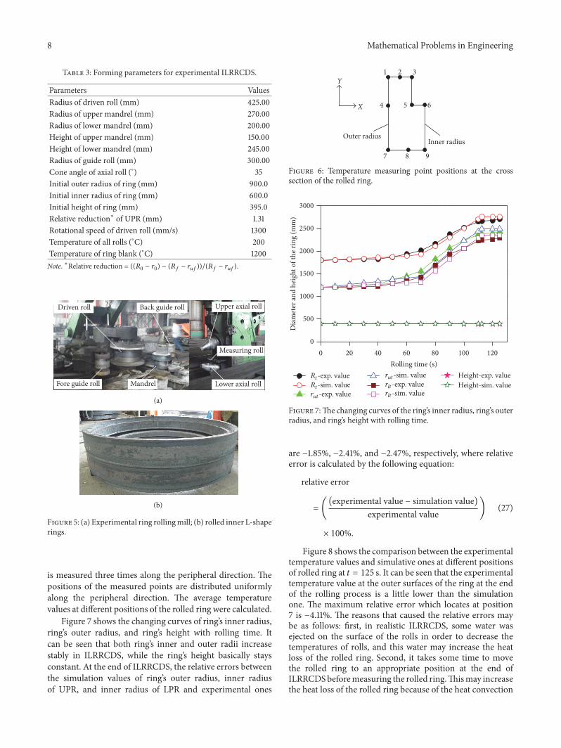
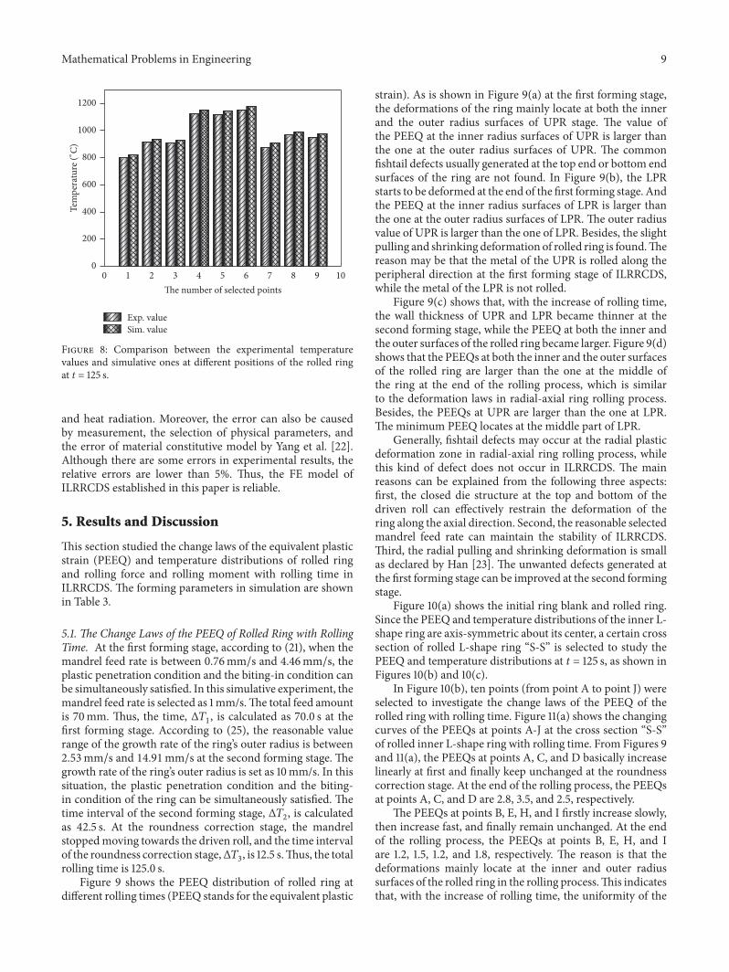
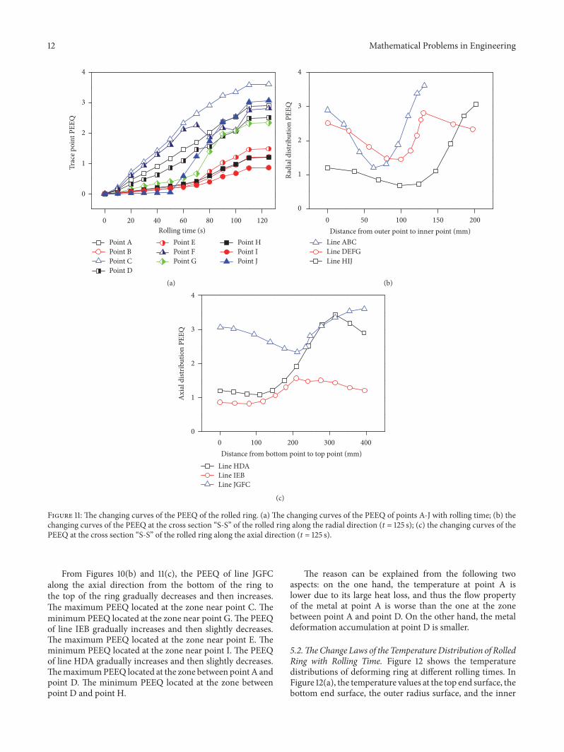