Embed Size (px)
Citation preview
rese
arch
repo
rt
Strength of CFS Floor Assemblies with Clip Angle Bearing Stiffeners
R E S E A R C H R E P O R T R P 0 5 - 6 2 0 0 5 R E V I S I O N 2 0 0 6
American Iron and Steel Institute
Strength of CFS Floor Assemblies with Clip Angle Bearing Stiffeners i
DISCLAIMER
The material contained herein has been developed by researchers based on their research findings and is for general information only. The information in it should not be used without first securing competent advice with respect to its suitability for any given application. The publication of the information is not intended as a representation or warranty on the part of the American Iron and Steel Institute, Steel Framing Alliance, or of any other person named herein, that the information is suitable for any general or particular use or of freedom from infringement of any patent or patents. Anyone making use of the information assumes all liability arising from such use.
Copyright 2005 American Iron and Steel Institute / Steel Framing Alliance Revised Edition Copyright 2006 American Iron and Steel Institute / Steel Framing Alliance
ii Strength of CFS Floor Assemblies with Clip Angle Bearing Stiffeners
PREFACE
The primary objective of this project was to develop design provisions for the utilization of clip angles as bearing stiffeners in cold-formed steel floor assemblies. This report presents the results of 120 end-two-flange loading tests of typical floor configurations carried out to check and compare joist depth and thickness, clip angle thickness and in-line and offset loading conditions.
The project developed a design methodology for the use of clip angle bearing stiffeners in cold-formed steel floor joist assemblies. These provisions are suitable for including in the proposed AISI Standard for Cold-Formed Steel Framing – Floor and Roof System Design (predictor equation) and the AISI Standard for Cold-Formed Steel Framing – General Provisions (offset conditions). In addition, provisions for clip angle bearing stiffeners should be added to the AISI Standard for Cold-Formed Steel Framing – Prescriptive Method for One and Two Family Dwellings based on these results.
Research Team Steel Framing Alliance
The Strength of CFS Floor Assemblies with Clip Angle Bearing Stiffeners
Prepared for the STEEL FRAMING ALLIANCE
and the STEEL STUD MANUFACTURERS ASSOCIATION
by Steven R. Fox, PhD, P.Eng.
Canadian Cold Formed Steel Research Group University of Waterloo
Waterloo, Ontario, Canada
October 17, 2005
i
Executive Summary Described in this report are the results of an experimental investigation into the strength of cold-formed steel floor assemblies utilizing clip angles as bearing stiffeners. The investigation consisted of 120 end-two-flange loading tests of typical floor configurations carried out to check and compare the following variables:
• joist depth and thickness; • clip angle thickness; • in-line and offset loading conditions.
The main conclusions reached are as follows:
• A recommendation is proposed for a design approach to calculate the capacity of a clip angle bearing stiffener. The predictor expression adds the web crippling capacity of the joist, the web crippling capacity of the rim track, and the axial capacity of the clip angle. To simplify the calculations of the capacity of the clip angle, a reduced stress on the gross area is used in lieu of the yield stress on an effective area.
• If the loadbearing stud is offset from the centerline of the floor joist such that the stud is bearing over the joist flange, there can be a reduction in the strength of the assembly accompanied by excessive deformations. Recommendations have been made for reductions in the predicted capacity for specific situations.
• Due to the interaction of the different components in the assembly (i.e. joist, rim track, clip angle, screws, wall track, and wall stud) there is a wide scatter in the test results not captured by the parameters in the predictor equation. Consequently, a conservative approach was taken in developing the proposed equation.
ii
Table of Contents Executive Summary ....................................................................................................................................... i Table of Contents ....................................................................................................................................... ii List of Figures ...................................................................................................................................... iii List of Tables ...................................................................................................................................... iii 1 Introduction ....................................................................................................................................... 1 2 Objective ....................................................................................................................................... 2 3 Scope ....................................................................................................................................... 2 4 Test Specimens and Experimental Set-Up ............................................................................................ 2
4.1 Test Specimens ..............................................................................................................2 4.2 Research Plan.................................................................................................................3 4.3 Mechanical Properties....................................................................................................6 4.4 Test Set-Up ....................................................................................................................6 4.5 Offset Loading ...............................................................................................................7
5 Discussion of Test Results .................................................................................................................... 8
5.1 Test Results....................................................................................................................8 5.2 Clip Angle Failure .......................................................................................................17 5.3 Excessive Deformation ................................................................................................17 5.4 Screw Shear .................................................................................................................18 5.5 Track Flange Failure ....................................................................................................19 5.6 Effect of Offset Loading ..............................................................................................20 5.7 Web Crippling Modes..................................................................................................21
6 Analysis of Results.............................................................................................................................. 22
6.1 Prediction Equation......................................................................................................22 6.2 Discussion of Results...................................................................................................26 6.3 Phi and Omega Factors ................................................................................................28
7 Recommendations ............................................................................................................................... 28 8 Acknowledgment ................................................................................................................................ 29 9 References ..................................................................................................................................... 29
iii
List of Figures 1.1 Failure of Floor Assembly with a Clip Angle Bearing Stiffener ....................................1 1.2 Results from Research by House et. al. ..........................................................................2 4.1 Test Configuration ..........................................................................................................7 4.2 Photograph of a Specimen Being Tested ........................................................................7 4.3 Offset Loading Conditions..............................................................................................8 5.1 Photograph of a Clip Angle Failure ..............................................................................17 5.2 Photograph of Excessive Deformation .........................................................................18 5.3 Photograph of Screw Shear without Clip Angle Failure ..............................................19 5.4 Photograph of Track Shear Failure ...............................................................................20 5.5 Load-Displacement Plots for Offset Loading of Inside Stiffener.................................21 5.6 Load-Displacement Plots for Offset Loading of Back Stiffener ..................................21 5.7 Web Buckling Failure Modes .......................................................................................22 6.1 Test/Predicted Ratios for All Data................................................................................26 6.2 Tilting of Loadbearing Stud..........................................................................................27 6.3 Screw Failure ................................................................................................................28
List of Tables 4.1 Test Configurations.........................................................................................................4 4.1 Test Configurations (Cont’d)..........................................................................................5 4.2 Mechanical Properties.....................................................................................................6 5.1 Test Results for Inside, In-Line Assemblies...................................................................9 5.1 Test Results for Inside, In-Line Assemblies (Cont’d) ..................................................10 5.2 Test Results for Back, In-Line Assemblies ..................................................................12 5.2 Test Results for Back, In-Line Assemblies (Cont’d)....................................................13 5.3 Test Results for Inside, Offset-Left Assemblies ...........................................................14 5.4 Test Results for Back, Offset-Left Assemblies.............................................................14 5.5 Test Results for Inside, Offset-Right Assemblies.........................................................15 5.6 Test Results for Back, Offset-Right Assemblies ..........................................................16 6.1 Test/Predictor Comparisons..........................................................................................25 6.2 Phi and Omega Factors .................................................................................................28
Clip Angle Bearing Stiffeners October 17, 2005
1
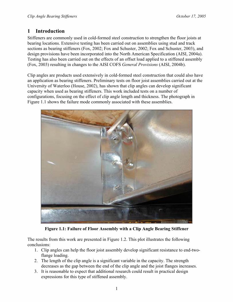
1 Introduction Stiffeners are commonly used in cold-formed steel construction to strengthen the floor joists at bearing locations. Extensive testing has been carried out on assemblies using stud and track sections as bearing stiffeners (Fox, 2002; Fox and Schuster, 2002; Fox and Schuster, 2003), and design provisions have been incorporated into the North American Specification (AISI, 2004a). Testing has also been carried out on the effects of an offset load applied to a stiffened assembly (Fox, 2003) resulting in changes to the AISI COFS General Provisions (AISI, 2004b). Clip angles are products used extensively in cold-formed steel construction that could also have an application as bearing stiffeners. Preliminary tests on floor joist assemblies carried out at the University of Waterloo (House, 2002), has shown that clip angles can develop significant capacity when used as bearing stiffeners. This work included tests on a number of configurations, focusing on the effect of clip angle length and thickness. The photograph in Figure 1.1 shows the failure mode commonly associated with these assemblies.
Figure 1.1: Failure of Floor Assembly with a Clip Angle Bearing Stiffener
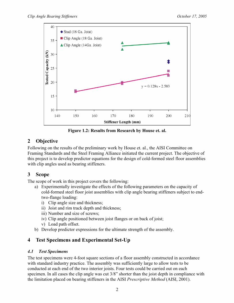
The results from this work are presented in Figure 1.2. This plot illustrates the following conclusions:
1. Clip angles can help the floor joist assembly develop significant resistance to end-two-flange loading.
2. The length of the clip angle is a significant variable in the capacity. The strength decreases as the gap between the end of the clip angle and the joist flanges increases.
3. It is reasonable to expect that additional research could result in practical design expressions for this type of stiffened assembly.
Clip Angle Bearing Stiffeners October 17, 2005
2
Figure 1.2: Results from Research by House et. al.
2 Objective Following on the results of the preliminary work by House et. al., the AISI Committee on Framing Standards and the Steel Framing Alliance initiated the current project. The objective of this project is to develop predictor equations for the design of cold-formed steel floor assemblies with clip angles used as bearing stiffeners.
3 Scope The scope of work in this project covers the following:
a) Experimentally investigate the effects of the following parameters on the capacity of cold-formed steel floor joist assemblies with clip angle bearing stiffeners subject to end-two-flange loading: i) Clip angle size and thickness; ii) Joist and rim track depth and thickness; iii) Number and size of screws; iv) Clip angle positioned between joist flanges or on back of joist; v) Load path offset.
b) Develop predictor expressions for the ultimate strength of the assembly.
4 Test Specimens and Experimental Set-Up
4.1 Test Specimens The test specimens were 4-foot square sections of a floor assembly constructed in accordance with standard industry practice. The assembly was sufficiently large to allow tests to be conducted at each end of the two interior joists. Four tests could be carried out on each specimen. In all cases the clip angle was cut 3/8” shorter than the joist depth in compliance with the limitation placed on bearing stiffeners in the AISI Prescriptive Method (AISI, 2001).
Clip Angle Bearing Stiffeners October 17, 2005
3
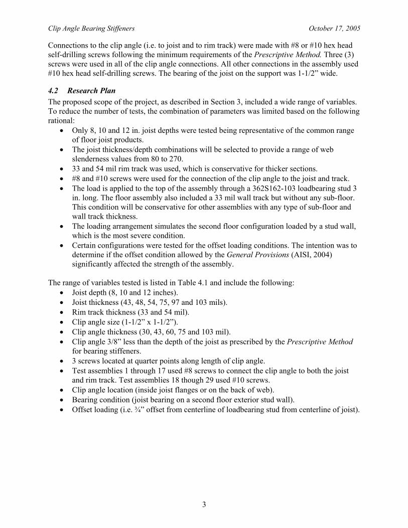
Connections to the clip angle (i.e. to joist and to rim track) were made with #8 or #10 hex head self-drilling screws following the minimum requirements of the Prescriptive Method. Three (3) screws were used in all of the clip angle connections. All other connections in the assembly used #10 hex head self-drilling screws. The bearing of the joist on the support was 1-1/2” wide.
4.2 Research Plan The proposed scope of the project, as described in Section 3, included a wide range of variables. To reduce the number of tests, the combination of parameters was limited based on the following rational:
• Only 8, 10 and 12 in. joist depths were tested being representative of the common range of floor joist products.
• The joist thickness/depth combinations will be selected to provide a range of web slenderness values from 80 to 270.
• 33 and 54 mil rim track was used, which is conservative for thicker sections. • #8 and #10 screws were used for the connection of the clip angle to the joist and track. • The load is applied to the top of the assembly through a 362S162-103 loadbearing stud 3
in. long. The floor assembly also included a 33 mil wall track but without any sub-floor. This condition will be conservative for other assemblies with any type of sub-floor and wall track thickness.
• The loading arrangement simulates the second floor configuration loaded by a stud wall, which is the most severe condition.
• Certain configurations were tested for the offset loading conditions. The intention was to determine if the offset condition allowed by the General Provisions (AISI, 2004) significantly affected the strength of the assembly.
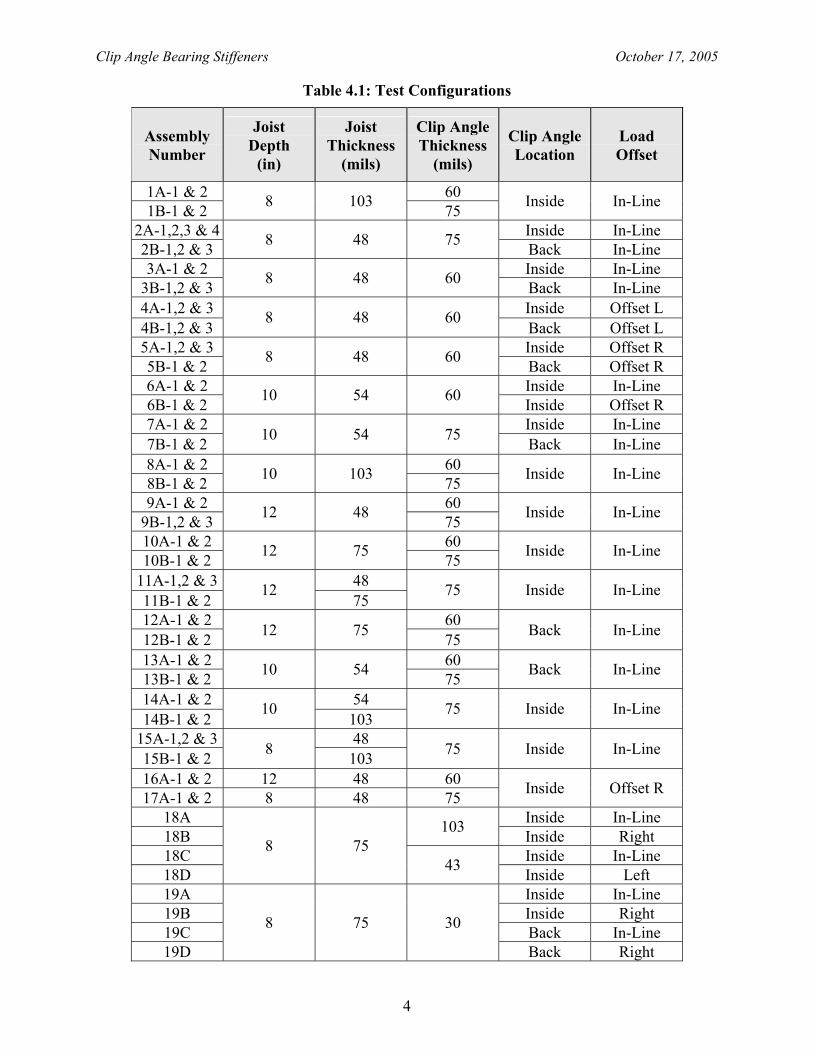
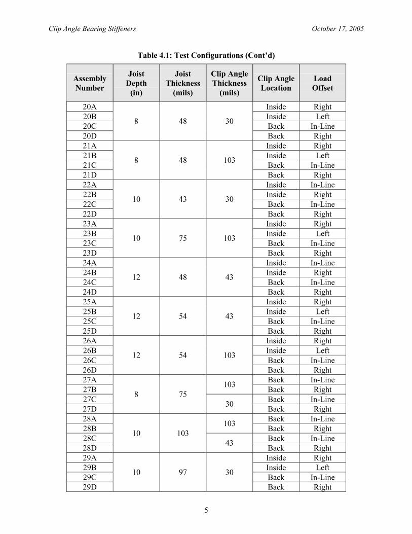
The range of variables tested is listed in Table 4.1 and include the following:
• Joist depth (8, 10 and 12 inches). • Joist thickness (43, 48, 54, 75, 97 and 103 mils). • Rim track thickness (33 and 54 mil). • Clip angle size (1-1/2” x 1-1/2”). • Clip angle thickness (30, 43, 60, 75 and 103 mil). • Clip angle 3/8” less than the depth of the joist as prescribed by the Prescriptive Method
for bearing stiffeners. • 3 screws located at quarter points along length of clip angle. • Test assemblies 1 through 17 used #8 screws to connect the clip angle to both the joist
and rim track. Test assemblies 18 though 29 used #10 screws. • Clip angle location (inside joist flanges or on the back of web). • Bearing condition (joist bearing on a second floor exterior stud wall). • Offset loading (i.e. ¾” offset from centerline of loadbearing stud from centerline of joist).
Clip Angle Bearing Stiffeners October 17, 2005
4
Table 4.1: Test Configurations
Assembly Number
Joist Depth
(in)
Joist Thickness
(mils)
Clip Angle Thickness
(mils)
Clip Angle Location
Load Offset
1A-1 & 2 60 1B-1 & 2 8 103 75 Inside In-Line
2A-1,2,3 & 4 Inside In-Line 2B-1,2 & 3 8 48 75 Back In-Line 3A-1 & 2 Inside In-Line
3B-1,2 & 3 8 48 60 Back In-Line 4A-1,2 & 3 Inside Offset L 4B-1,2 & 3
8 48 60 Back Offset L
5A-1,2 & 3 Inside Offset R 5B-1 & 2 8 48 60 Back Offset R 6A-1 & 2 Inside In-Line 6B-1 & 2 10 54 60 Inside Offset R 7A-1 & 2 Inside In-Line 7B-1 & 2 10 54 75 Back In-Line 8A-1 & 2 60 8B-1 & 2 10 103 75 Inside In-Line
9A-1 & 2 60 9B-1,2 & 3 12 48 75 Inside In-Line
10A-1 & 2 60 10B-1 & 2 12 75 75 Inside In-Line
11A-1,2 & 3 48 11B-1 & 2
12 75
75 Inside In-Line
12A-1 & 2 60 12B-1 & 2 12 75 75 Back In-Line
13A-1 & 2 60 13B-1 & 2 10 54 75 Back In-Line
14A-1 & 2 54 14B-1 & 2
10 103
75 Inside In-Line
15A-1,2 & 3 48 15B-1 & 2 8 103 75 Inside In-Line
16A-1 & 2 12 48 60 17A-1 & 2 8 48 75 Inside Offset R
18A Inside In-Line 18B 103 Inside Right 18C Inside In-Line 18D
8 75 43 Inside Left
19A Inside In-Line 19B Inside Right 19C Back In-Line 19D
8 75 30
Back Right
Clip Angle Bearing Stiffeners October 17, 2005
5
Table 4.1: Test Configurations (Cont’d)
Assembly Number
Joist Depth
(in)
Joist Thickness
(mils)
Clip Angle Thickness
(mils)
Clip Angle Location
Load Offset
20A Inside Right 20B Inside Left 20C Back In-Line 20D
8 48 30
Back Right 21A Inside Right 21B Inside Left 21C Back In-Line 21D
8 48 103
Back Right 22A Inside In-Line 22B Inside Right 22C Back In-Line 22D
10 43 30
Back Right 23A Inside Right 23B Inside Left 23C Back In-Line 23D
10 75 103
Back Right 24A Inside In-Line 24B Inside Right 24C Back In-Line 24D
12 48 43
Back Right 25A Inside Right 25B Inside Left 25C Back In-Line 25D
12 54 43
Back Right 26A Inside Right 26B Inside Left 26C Back In-Line 26D
12 54 103
Back Right 27A Back In-Line 27B 103 Back Right 27C Back In-Line 27D
8 75 30 Back Right
28A Back In-Line 28B 103 Back Right 28C Back In-Line 28D
10 103 43 Back Right
29A Inside Right 29B Inside Left 29C Back In-Line 29D
10 97 30
Back Right
Clip Angle Bearing Stiffeners October 17, 2005
6
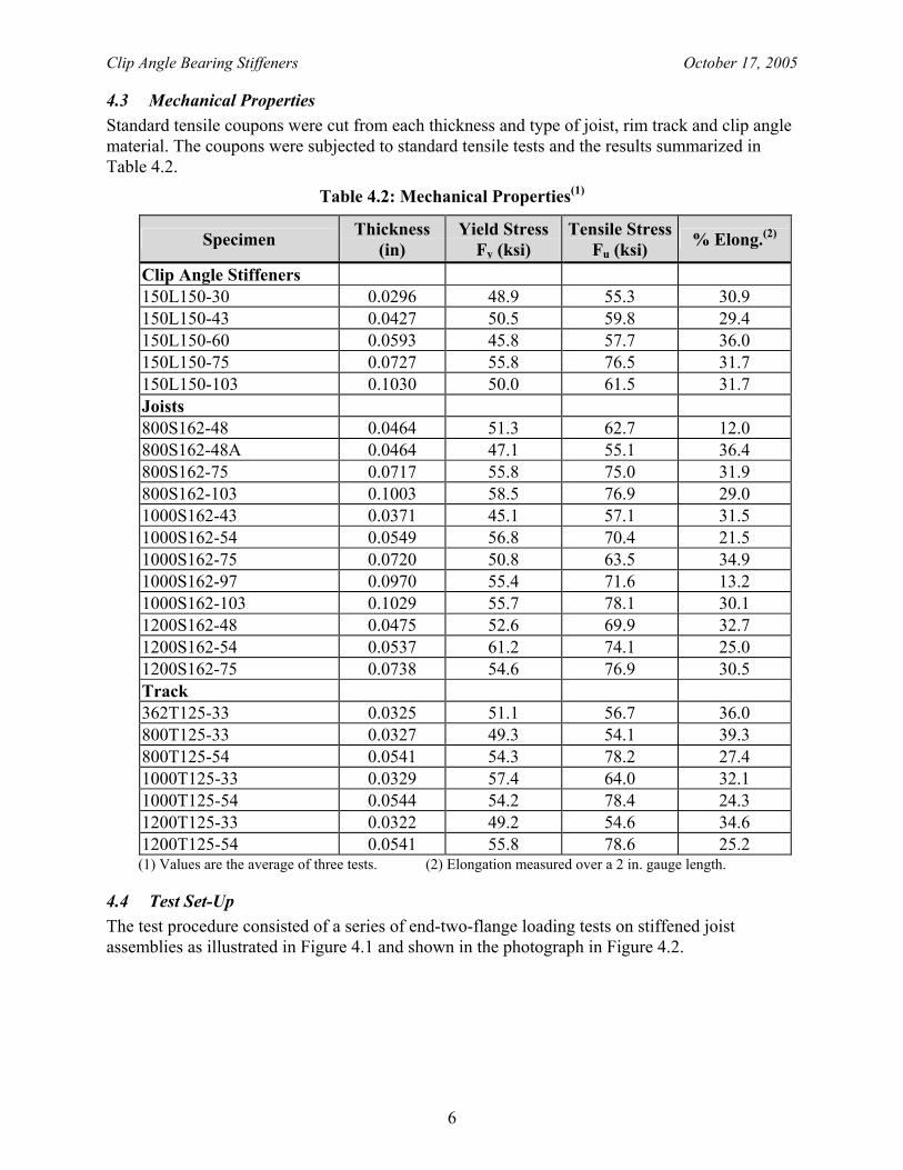
4.3 Mechanical Properties Standard tensile coupons were cut from each thickness and type of joist, rim track and clip angle material. The coupons were subjected to standard tensile tests and the results summarized in Table 4.2.
Table 4.2: Mechanical Properties(1)
Specimen Thickness (in)
Yield Stress Fy (ksi)
Tensile Stress Fu (ksi) % Elong.(2)
Clip Angle Stiffeners 150L150-30 0.0296 48.9 55.3 30.9 150L150-43 0.0427 50.5 59.8 29.4 150L150-60 0.0593 45.8 57.7 36.0 150L150-75 0.0727 55.8 76.5 31.7 150L150-103 0.1030 50.0 61.5 31.7 Joists 800S162-48 0.0464 51.3 62.7 12.0 800S162-48A 0.0464 47.1 55.1 36.4 800S162-75 0.0717 55.8 75.0 31.9 800S162-103 0.1003 58.5 76.9 29.0 1000S162-43 0.0371 45.1 57.1 31.5 1000S162-54 0.0549 56.8 70.4 21.5 1000S162-75 0.0720 50.8 63.5 34.9 1000S162-97 0.0970 55.4 71.6 13.2 1000S162-103 0.1029 55.7 78.1 30.1 1200S162-48 0.0475 52.6 69.9 32.7 1200S162-54 0.0537 61.2 74.1 25.0 1200S162-75 0.0738 54.6 76.9 30.5 Track 362T125-33 0.0325 51.1 56.7 36.0 800T125-33 0.0327 49.3 54.1 39.3 800T125-54 0.0541 54.3 78.2 27.4 1000T125-33 0.0329 57.4 64.0 32.1 1000T125-54 0.0544 54.2 78.4 24.3 1200T125-33 0.0322 49.2 54.6 34.6 1200T125-54 0.0541 55.8 78.6 25.2 (1) Values are the average of three tests. (2) Elongation measured over a 2 in. gauge length.
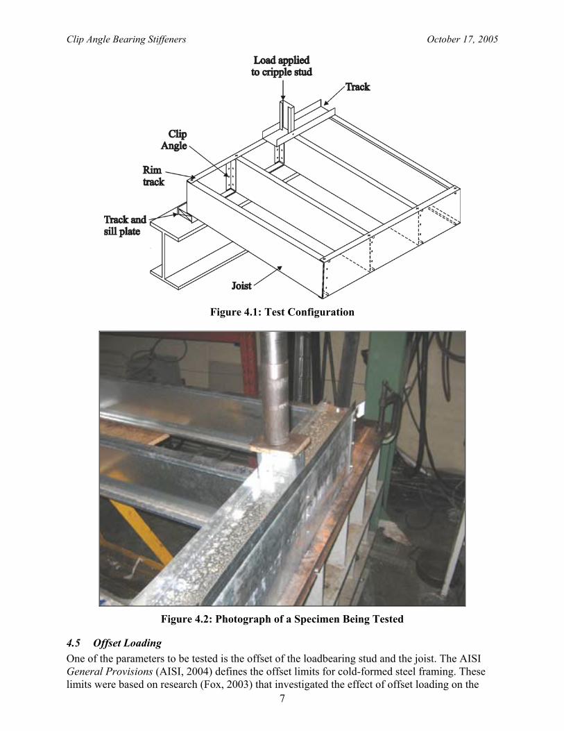
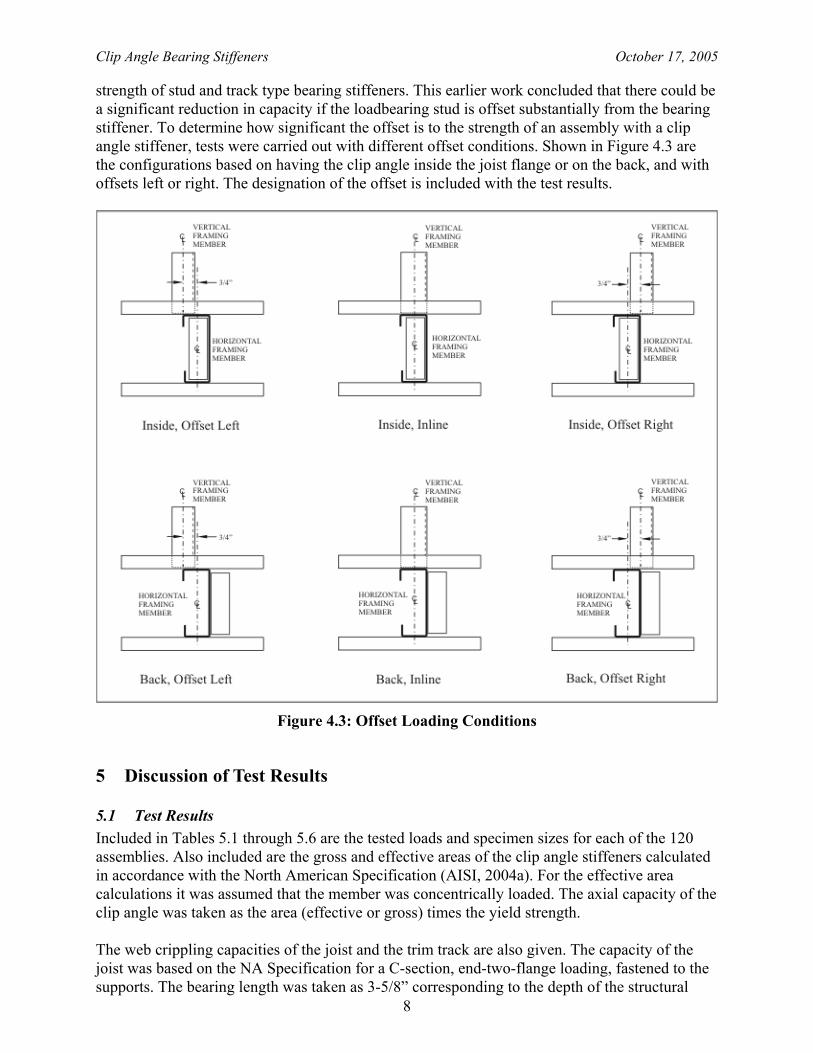
4.4 Test Set-Up The test procedure consisted of a series of end-two-flange loading tests on stiffened joist assemblies as illustrated in Figure 4.1 and shown in the photograph in Figure 4.2.
Clip Angle Bearing Stiffeners October 17, 2005
7
Figure 4.1: Test Configuration
Figure 4.2: Photograph of a Specimen Being Tested
4.5 Offset Loading One of the parameters to be tested is the offset of the loadbearing stud and the joist. The AISI General Provisions (AISI, 2004) defines the offset limits for cold-formed steel framing. These limits were based on research (Fox, 2003) that investigated the effect of offset loading on the
Clip Angle Bearing Stiffeners October 17, 2005
8
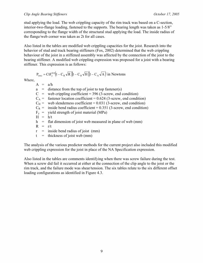
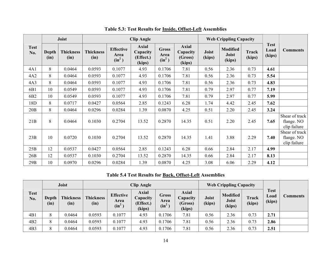
strength of stud and track type bearing stiffeners. This earlier work concluded that there could be a significant reduction in capacity if the loadbearing stud is offset substantially from the bearing stiffener. To determine how significant the offset is to the strength of an assembly with a clip angle stiffener, tests were carried out with different offset conditions. Shown in Figure 4.3 are the configurations based on having the clip angle inside the joist flange or on the back, and with offsets left or right. The designation of the offset is included with the test results.
Figure 4.3: Offset Loading Conditions
5 Discussion of Test Results
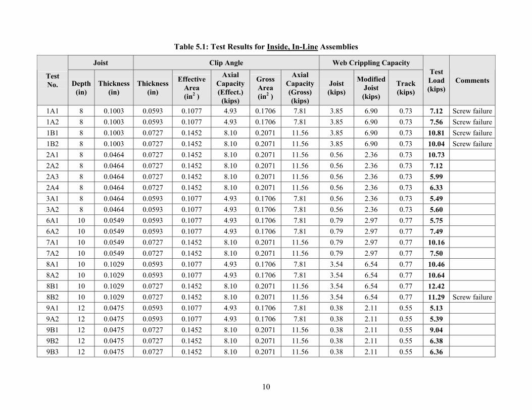
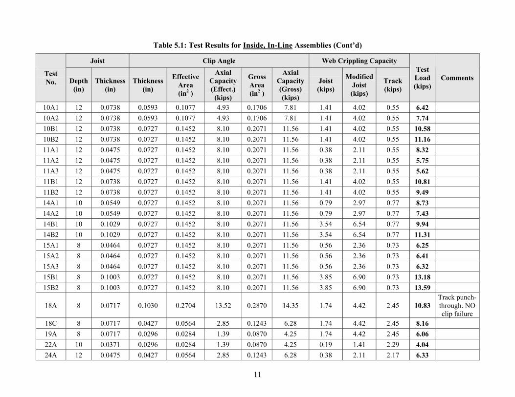
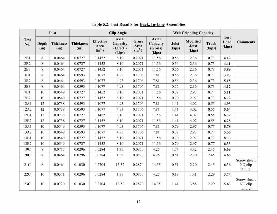
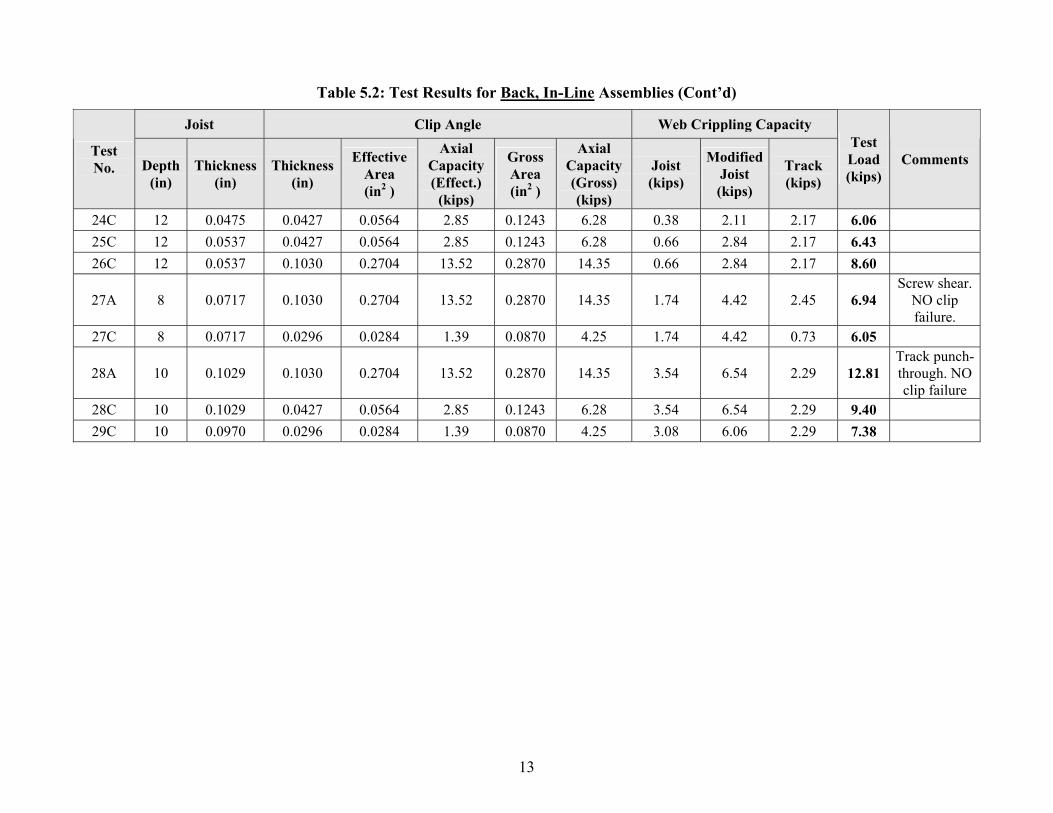
5.1 Test Results Included in Tables 5.1 through 5.6 are the tested loads and specimen sizes for each of the 120 assemblies. Also included are the gross and effective areas of the clip angle stiffeners calculated in accordance with the North American Specification (AISI, 2004a). For the effective area calculations it was assumed that the member was concentrically loaded. The axial capacity of the clip angle was taken as the area (effective or gross) times the yield strength. The web crippling capacities of the joist and the trim track are also given. The capacity of the joist was based on the NA Specification for a C-section, end-two-flange loading, fastened to the supports. The bearing length was taken as 3-5/8” corresponding to the depth of the structural
Clip Angle Bearing Stiffeners October 17, 2005
9
stud applying the load. The web crippling capacity of the rim track was based on a C-section, interior-two-flange loading, fastened to the supports. The bearing length was taken as 1-5/8” corresponding to the flange width of the structural stud applying the load. The inside radius of the flange/web corner was taken as 2t for all cases. Also listed in the tables are modified web crippling capacities for the joist. Research into the behavior of stud and track bearing stiffeners (Fox, 2002) determined that the web crippling behaviour of the joist in a stiffened assembly was affected by the connection of the joist to the bearing stiffener. A modified web crippling expression was proposed for a joist with a bearing stiffener. This expression is as follows:
( )( )( )AC1HC1RC1CtFP AHR
8.0ynwc −−−= in Newtons
Where, A = a/h a = distance from the top of joist to top fastener(s)
C = web crippling coefficient = 396 (3-screw, end condition) CA = fastener location coefficient = 0.624 (3-screw, end condition) CH = web slenderness coefficient = 0.031 (3-screw, end condition)
CR = inside bend radius coefficient = 0.351 (3-screw, end condition) Fy = yield strength of joist material (MPa) H = h/t h = flat dimension of joist web measured in plane of web (mm) R = r/t r = inside bend radius of joist (mm)
t = thickness of joist web (mm) The analysis of the various predictor methods for the current project also included this modified web crippling expression for the joist in place of the NA Specification expression. Also listed in the tables are comments identifying when there was screw failure during the test. When a screw did fail it occurred at either at the connection of the clip angle to the joist or the rim track, and the failure mode was shear/tension. The six tables relate to the six different offset loading configurations as identified in Figure 4.3.
10
Table 5.1: Test Results for Inside, In-Line Assemblies
Joist Clip Angle Web Crippling Capacity
Test No. Depth
(in) Thickness
(in) Thickness
(in)
Effective Area (in2 )
Axial Capacity (Effect.)
(kips)
Gross Area (in2 )
Axial Capacity (Gross) (kips)
Joist (kips)
ModifiedJoist (kips)
Track (kips)
Test Load (kips)
Comments
1A1 8 0.1003 0.0593 0.1077 4.93 0.1706 7.81 3.85 6.90 0.73 7.12 Screw failure1A2 8 0.1003 0.0593 0.1077 4.93 0.1706 7.81 3.85 6.90 0.73 7.56 Screw failure1B1 8 0.1003 0.0727 0.1452 8.10 0.2071 11.56 3.85 6.90 0.73 10.81 Screw failure1B2 8 0.1003 0.0727 0.1452 8.10 0.2071 11.56 3.85 6.90 0.73 10.04 Screw failure2A1 8 0.0464 0.0727 0.1452 8.10 0.2071 11.56 0.56 2.36 0.73 10.73 2A2 8 0.0464 0.0727 0.1452 8.10 0.2071 11.56 0.56 2.36 0.73 7.12 2A3 8 0.0464 0.0727 0.1452 8.10 0.2071 11.56 0.56 2.36 0.73 5.99 2A4 8 0.0464 0.0727 0.1452 8.10 0.2071 11.56 0.56 2.36 0.73 6.33 3A1 8 0.0464 0.0593 0.1077 4.93 0.1706 7.81 0.56 2.36 0.73 5.49 3A2 8 0.0464 0.0593 0.1077 4.93 0.1706 7.81 0.56 2.36 0.73 5.60 6A1 10 0.0549 0.0593 0.1077 4.93 0.1706 7.81 0.79 2.97 0.77 5.75 6A2 10 0.0549 0.0593 0.1077 4.93 0.1706 7.81 0.79 2.97 0.77 7.49 7A1 10 0.0549 0.0727 0.1452 8.10 0.2071 11.56 0.79 2.97 0.77 10.16 7A2 10 0.0549 0.0727 0.1452 8.10 0.2071 11.56 0.79 2.97 0.77 7.50 8A1 10 0.1029 0.0593 0.1077 4.93 0.1706 7.81 3.54 6.54 0.77 10.46 8A2 10 0.1029 0.0593 0.1077 4.93 0.1706 7.81 3.54 6.54 0.77 10.64 8B1 10 0.1029 0.0727 0.1452 8.10 0.2071 11.56 3.54 6.54 0.77 12.42 8B2 10 0.1029 0.0727 0.1452 8.10 0.2071 11.56 3.54 6.54 0.77 11.29 Screw failure9A1 12 0.0475 0.0593 0.1077 4.93 0.1706 7.81 0.38 2.11 0.55 5.13 9A2 12 0.0475 0.0593 0.1077 4.93 0.1706 7.81 0.38 2.11 0.55 5.39 9B1 12 0.0475 0.0727 0.1452 8.10 0.2071 11.56 0.38 2.11 0.55 9.04 9B2 12 0.0475 0.0727 0.1452 8.10 0.2071 11.56 0.38 2.11 0.55 6.38 9B3 12 0.0475 0.0727 0.1452 8.10 0.2071 11.56 0.38 2.11 0.55 6.36
11
Table 5.1: Test Results for Inside, In-Line Assemblies (Cont’d)
Joist Clip Angle Web Crippling Capacity
Test No. Depth
(in) Thickness
(in) Thickness
(in)
Effective Area (in2 )
Axial Capacity (Effect.)
(kips)
Gross Area (in2 )
Axial Capacity (Gross) (kips)
Joist (kips)
ModifiedJoist (kips)
Track (kips)
Test Load (kips)
Comments
10A1 12 0.0738 0.0593 0.1077 4.93 0.1706 7.81 1.41 4.02 0.55 6.42 10A2 12 0.0738 0.0593 0.1077 4.93 0.1706 7.81 1.41 4.02 0.55 7.74 10B1 12 0.0738 0.0727 0.1452 8.10 0.2071 11.56 1.41 4.02 0.55 10.58 10B2 12 0.0738 0.0727 0.1452 8.10 0.2071 11.56 1.41 4.02 0.55 11.16 11A1 12 0.0475 0.0727 0.1452 8.10 0.2071 11.56 0.38 2.11 0.55 8.32 11A2 12 0.0475 0.0727 0.1452 8.10 0.2071 11.56 0.38 2.11 0.55 5.75 11A3 12 0.0475 0.0727 0.1452 8.10 0.2071 11.56 0.38 2.11 0.55 5.62 11B1 12 0.0738 0.0727 0.1452 8.10 0.2071 11.56 1.41 4.02 0.55 10.81 11B2 12 0.0738 0.0727 0.1452 8.10 0.2071 11.56 1.41 4.02 0.55 9.49 14A1 10 0.0549 0.0727 0.1452 8.10 0.2071 11.56 0.79 2.97 0.77 8.73 14A2 10 0.0549 0.0727 0.1452 8.10 0.2071 11.56 0.79 2.97 0.77 7.43 14B1 10 0.1029 0.0727 0.1452 8.10 0.2071 11.56 3.54 6.54 0.77 9.94 14B2 10 0.1029 0.0727 0.1452 8.10 0.2071 11.56 3.54 6.54 0.77 11.31 15A1 8 0.0464 0.0727 0.1452 8.10 0.2071 11.56 0.56 2.36 0.73 6.25 15A2 8 0.0464 0.0727 0.1452 8.10 0.2071 11.56 0.56 2.36 0.73 6.41 15A3 8 0.0464 0.0727 0.1452 8.10 0.2071 11.56 0.56 2.36 0.73 6.32 15B1 8 0.1003 0.0727 0.1452 8.10 0.2071 11.56 3.85 6.90 0.73 13.18 15B2 8 0.1003 0.0727 0.1452 8.10 0.2071 11.56 3.85 6.90 0.73 13.59
18A 8 0.0717 0.1030 0.2704 13.52 0.2870 14.35 1.74 4.42 2.45 10.83 Track punch-through. NO clip failure
18C 8 0.0717 0.0427 0.0564 2.85 0.1243 6.28 1.74 4.42 2.45 8.16 19A 8 0.0717 0.0296 0.0284 1.39 0.0870 4.25 1.74 4.42 2.45 6.06 22A 10 0.0371 0.0296 0.0284 1.39 0.0870 4.25 0.19 1.41 2.29 4.04 24A 12 0.0475 0.0427 0.0564 2.85 0.1243 6.28 0.38 2.11 2.17 6.33
12
Table 5.2: Test Results for Back, In-Line Assemblies
Joist Clip Angle Web Crippling Capacity
Test No. Depth
(in) Thickness
(in) Thickness
(in)
Effective Area (in2 )
Axial Capacity (Effect.)
(kips)
Gross Area (in2 )
Axial Capacity (Gross) (kips)
Joist (kips)
ModifiedJoist (kips)
Track (kips)
Test Load (kips)
Comments
2B1 8 0.0464 0.0727 0.1452 8.10 0.2071 11.56 0.56 2.36 0.73 4.12 2B2 8 0.0464 0.0727 0.1452 8.10 0.2071 11.56 0.56 2.36 0.73 4.41 2B3 8 0.0464 0.0727 0.1452 8.10 0.2071 11.56 0.56 2.36 0.73 3.89 3B1 8 0.0464 0.0593 0.1077 4.93 0.1706 7.81 0.56 2.36 0.73 3.93 3B2 8 0.0464 0.0593 0.1077 4.93 0.1706 7.81 0.56 2.36 0.73 5.15 3B3 8 0.0464 0.0593 0.1077 4.93 0.1706 7.81 0.56 2.36 0.73 4.12 7B1 10 0.0549 0.0727 0.1452 8.10 0.2071 11.56 0.79 2.97 0.77 5.11 7B2 10 0.0549 0.0727 0.1452 8.10 0.2071 11.56 0.79 2.97 0.77 6.72
12A1 12 0.0738 0.0593 0.1077 4.93 0.1706 7.81 1.41 4.02 0.55 4.93 12A2 12 0.0738 0.0593 0.1077 4.93 0.1706 7.81 1.41 4.02 0.55 5.64 12B1 12 0.0738 0.0727 0.1452 8.10 0.2071 11.56 1.41 4.02 0.55 6.72 12B2 12 0.0738 0.0727 0.1452 8.10 0.2071 11.56 1.41 4.02 0.55 6.28 13A1 10 0.0549 0.0593 0.1077 4.93 0.1706 7.81 0.79 2.97 0.77 5.78 13A2 10 0.0549 0.0593 0.1077 4.93 0.1706 7.81 0.79 2.97 0.77 5.55 13B1 10 0.0549 0.0727 0.1452 8.10 0.2071 11.56 0.79 2.97 0.77 8.33 13B2 10 0.0549 0.0727 0.1452 8.10 0.2071 11.56 0.79 2.97 0.77 6.33 19C 8 0.0717 0.0296 0.0284 1.39 0.0870 4.25 1.74 4.42 2.45 6.69 20C 8 0.0464 0.0296 0.0284 1.39 0.0870 4.25 0.51 2.20 2.45 4.65
21C 8 0.0464 0.1030 0.2704 13.52 0.2870 14.35 0.51 2.20 2.45 6.36 Screw shear.
NO clip failure.
22C 10 0.0371 0.0296 0.0284 1.39 0.0870 4.25 0.19 1.41 2.29 3.74
23C 10 0.0720 0.1030 0.2704 13.52 0.2870 14.35 1.41 3.88 2.29 5.63 Screw shear.
NO clip failure.
13
Table 5.2: Test Results for Back, In-Line Assemblies (Cont’d)
Joist Clip Angle Web Crippling Capacity
Test No. Depth
(in) Thickness
(in) Thickness
(in)
Effective Area (in2 )
Axial Capacity (Effect.)
(kips)
Gross Area (in2 )
Axial Capacity (Gross) (kips)
Joist (kips)
ModifiedJoist (kips)
Track (kips)
Test Load (kips)
Comments
24C 12 0.0475 0.0427 0.0564 2.85 0.1243 6.28 0.38 2.11 2.17 6.06 25C 12 0.0537 0.0427 0.0564 2.85 0.1243 6.28 0.66 2.84 2.17 6.43 26C 12 0.0537 0.1030 0.2704 13.52 0.2870 14.35 0.66 2.84 2.17 8.60
27A 8 0.0717 0.1030 0.2704 13.52 0.2870 14.35 1.74 4.42 2.45 6.94 Screw shear.
NO clip failure.
27C 8 0.0717 0.0296 0.0284 1.39 0.0870 4.25 1.74 4.42 0.73 6.05
28A 10 0.1029 0.1030 0.2704 13.52 0.2870 14.35 3.54 6.54 2.29 12.81 Track punch-through. NO clip failure
28C 10 0.1029 0.0427 0.0564 2.85 0.1243 6.28 3.54 6.54 2.29 9.40 29C 10 0.0970 0.0296 0.0284 1.39 0.0870 4.25 3.08 6.06 2.29 7.38
14
Table 5.3: Test Results for Inside, Offset-Left Assemblies
Joist Clip Angle Web Crippling Capacity
Test No. Depth
(in) Thickness
(in) Thickness
(in)
Effective Area (in2 )
Axial Capacity (Effect.)
(kips)
Gross Area (in2 )
Axial Capacity (Gross) (kips)
Joist (kips)
ModifiedJoist (kips)
Track (kips)
Test Load (kips)
Comments
4A1 8 0.0464 0.0593 0.1077 4.93 0.1706 7.81 0.56 2.36 0.73 4.61 4A2 8 0.0464 0.0593 0.1077 4.93 0.1706 7.81 0.56 2.36 0.73 5.54 4A3 8 0.0464 0.0593 0.1077 4.93 0.1706 7.81 0.56 2.36 0.73 4.83 6B1 10 0.0549 0.0593 0.1077 4.93 0.1706 7.81 0.79 2.97 0.77 7.19 6B2 10 0.0549 0.0593 0.1077 4.93 0.1706 7.81 0.79 2.97 0.77 5.99 18D 8 0.0717 0.0427 0.0564 2.85 0.1243 6.28 1.74 4.42 2.45 7.62 20B 8 0.0464 0.0296 0.0284 1.39 0.0870 4.25 0.51 2.20 2.45 3.24
21B 8 0.0464 0.1030 0.2704 13.52 0.2870 14.35 0.51 2.20 2.45 7.65 Shear of track
flange. NO clip failure
23B 10 0.0720 0.1030 0.2704 13.52 0.2870 14.35 1.41 3.88 2.29 7.40 Shear of track
flange. NO clip failure
25B 12 0.0537 0.0427 0.0564 2.85 0.1243 6.28 0.66 2.84 2.17 4.99 26B 12 0.0537 0.1030 0.2704 13.52 0.2870 14.35 0.66 2.84 2.17 8.13 29B 10 0.0970 0.0296 0.0284 1.39 0.0870 4.25 3.08 6.06 2.29 4.12
Table 5.4 Test Results for Back, Offset-Left Assemblies
Joist Clip Angle Web Crippling Capacity
Test No. Depth
(in) Thickness
(in) Thickness
(in)
Effective Area (in2 )
Axial Capacity (Effect.)
(kips)
Gross Area (in2 )
Axial Capacity (Gross) (kips)
Joist (kips)
ModifiedJoist (kips)
Track (kips)
Test Load (kips)
Comments
4B1 8 0.0464 0.0593 0.1077 4.93 0.1706 7.81 0.56 2.36 0.73 2.71 4B2 8 0.0464 0.0593 0.1077 4.93 0.1706 7.81 0.56 2.36 0.73 2.86 4B3 8 0.0464 0.0593 0.1077 4.93 0.1706 7.81 0.56 2.36 0.73 2.51
15
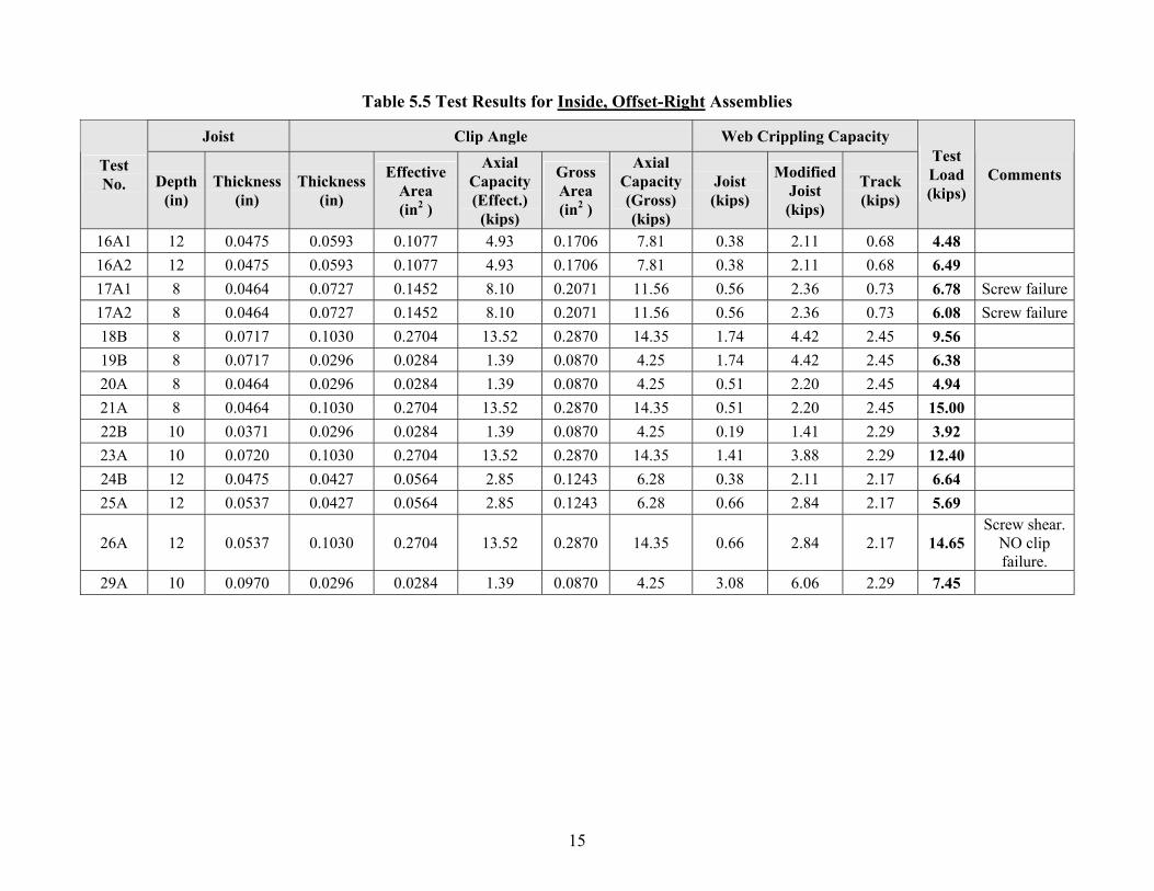
Table 5.5 Test Results for Inside, Offset-Right Assemblies
Joist Clip Angle Web Crippling Capacity
Test No. Depth
(in) Thickness
(in) Thickness
(in)
Effective Area (in2 )
Axial Capacity (Effect.)
(kips)
Gross Area (in2 )
Axial Capacity (Gross) (kips)
Joist (kips)
ModifiedJoist (kips)
Track (kips)
Test Load (kips)
Comments
16A1 12 0.0475 0.0593 0.1077 4.93 0.1706 7.81 0.38 2.11 0.68 4.48 16A2 12 0.0475 0.0593 0.1077 4.93 0.1706 7.81 0.38 2.11 0.68 6.49 17A1 8 0.0464 0.0727 0.1452 8.10 0.2071 11.56 0.56 2.36 0.73 6.78 Screw failure17A2 8 0.0464 0.0727 0.1452 8.10 0.2071 11.56 0.56 2.36 0.73 6.08 Screw failure18B 8 0.0717 0.1030 0.2704 13.52 0.2870 14.35 1.74 4.42 2.45 9.56 19B 8 0.0717 0.0296 0.0284 1.39 0.0870 4.25 1.74 4.42 2.45 6.38 20A 8 0.0464 0.0296 0.0284 1.39 0.0870 4.25 0.51 2.20 2.45 4.94 21A 8 0.0464 0.1030 0.2704 13.52 0.2870 14.35 0.51 2.20 2.45 15.00 22B 10 0.0371 0.0296 0.0284 1.39 0.0870 4.25 0.19 1.41 2.29 3.92 23A 10 0.0720 0.1030 0.2704 13.52 0.2870 14.35 1.41 3.88 2.29 12.40 24B 12 0.0475 0.0427 0.0564 2.85 0.1243 6.28 0.38 2.11 2.17 6.64 25A 12 0.0537 0.0427 0.0564 2.85 0.1243 6.28 0.66 2.84 2.17 5.69
26A 12 0.0537 0.1030 0.2704 13.52 0.2870 14.35 0.66 2.84 2.17 14.65 Screw shear.
NO clip failure.
29A 10 0.0970 0.0296 0.0284 1.39 0.0870 4.25 3.08 6.06 2.29 7.45
16
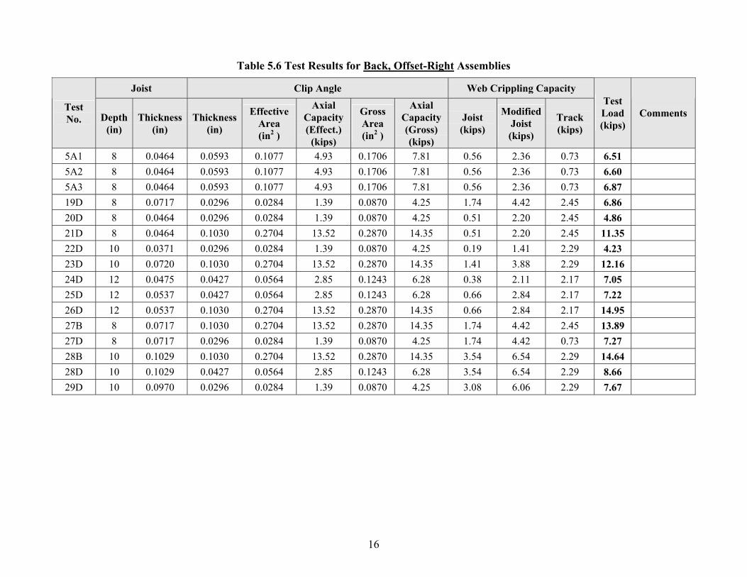
Table 5.6 Test Results for Back, Offset-Right Assemblies
Joist Clip Angle Web Crippling Capacity
Test No. Depth
(in) Thickness
(in) Thickness
(in)
Effective Area (in2 )
Axial Capacity (Effect.)
(kips)
Gross Area (in2 )
Axial Capacity (Gross) (kips)
Joist (kips)
ModifiedJoist (kips)
Track (kips)
Test Load (kips)
Comments
5A1 8 0.0464 0.0593 0.1077 4.93 0.1706 7.81 0.56 2.36 0.73 6.51 5A2 8 0.0464 0.0593 0.1077 4.93 0.1706 7.81 0.56 2.36 0.73 6.60 5A3 8 0.0464 0.0593 0.1077 4.93 0.1706 7.81 0.56 2.36 0.73 6.87 19D 8 0.0717 0.0296 0.0284 1.39 0.0870 4.25 1.74 4.42 2.45 6.86 20D 8 0.0464 0.0296 0.0284 1.39 0.0870 4.25 0.51 2.20 2.45 4.86 21D 8 0.0464 0.1030 0.2704 13.52 0.2870 14.35 0.51 2.20 2.45 11.35 22D 10 0.0371 0.0296 0.0284 1.39 0.0870 4.25 0.19 1.41 2.29 4.23 23D 10 0.0720 0.1030 0.2704 13.52 0.2870 14.35 1.41 3.88 2.29 12.16 24D 12 0.0475 0.0427 0.0564 2.85 0.1243 6.28 0.38 2.11 2.17 7.05 25D 12 0.0537 0.0427 0.0564 2.85 0.1243 6.28 0.66 2.84 2.17 7.22 26D 12 0.0537 0.1030 0.2704 13.52 0.2870 14.35 0.66 2.84 2.17 14.95 27B 8 0.0717 0.1030 0.2704 13.52 0.2870 14.35 1.74 4.42 2.45 13.89 27D 8 0.0717 0.0296 0.0284 1.39 0.0870 4.25 1.74 4.42 0.73 7.27 28B 10 0.1029 0.1030 0.2704 13.52 0.2870 14.35 3.54 6.54 2.29 14.64 28D 10 0.1029 0.0427 0.0564 2.85 0.1243 6.28 3.54 6.54 2.29 8.66 29D 10 0.0970 0.0296 0.0284 1.39 0.0870 4.25 3.08 6.06 2.29 7.67
Clip Angle Bearing Stiffeners October 17, 2005
17
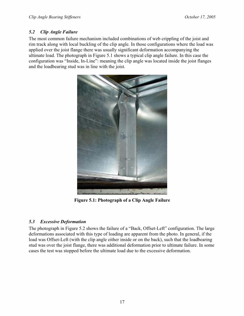
5.2 Clip Angle Failure The most common failure mechanism included combinations of web crippling of the joist and rim track along with local buckling of the clip angle. In those configurations where the load was applied over the joist flange there was usually significant deformation accompanying the ultimate load. The photograph in Figure 5.1 shows a typical clip angle failure. In this case the configuration was “Inside, In-Line”: meaning the clip angle was located inside the joist flanges and the loadbearing stud was in line with the joist.
Figure 5.1: Photograph of a Clip Angle Failure
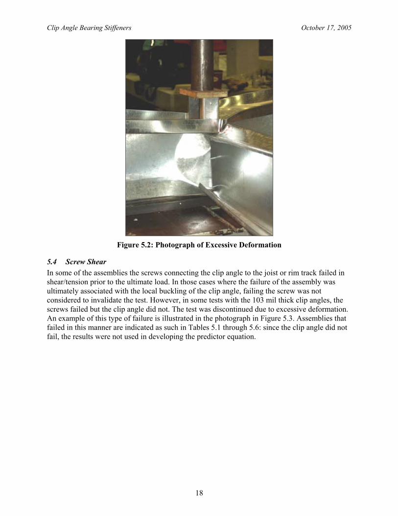
5.3 Excessive Deformation The photograph in Figure 5.2 shows the failure of a “Back, Offset-Left” configuration. The large deformations associated with this type of loading are apparent from the photo. In general, if the load was Offset-Left (with the clip angle either inside or on the back), such that the loadbearing stud was over the joist flange, there was additional deformation prior to ultimate failure. In some cases the test was stopped before the ultimate load due to the excessive deformation.
Clip Angle Bearing Stiffeners October 17, 2005
18
Figure 5.2: Photograph of Excessive Deformation
5.4 Screw Shear In some of the assemblies the screws connecting the clip angle to the joist or rim track failed in shear/tension prior to the ultimate load. In those cases where the failure of the assembly was ultimately associated with the local buckling of the clip angle, failing the screw was not considered to invalidate the test. However, in some tests with the 103 mil thick clip angles, the screws failed but the clip angle did not. The test was discontinued due to excessive deformation. An example of this type of failure is illustrated in the photograph in Figure 5.3. Assemblies that failed in this manner are indicated as such in Tables 5.1 through 5.6: since the clip angle did not fail, the results were not used in developing the predictor equation.
Clip Angle Bearing Stiffeners October 17, 2005
19
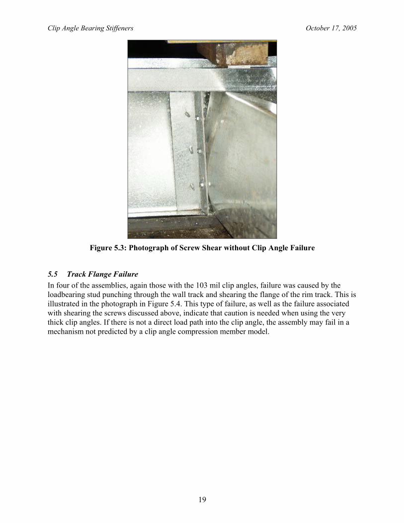
Figure 5.3: Photograph of Screw Shear without Clip Angle Failure
5.5 Track Flange Failure In four of the assemblies, again those with the 103 mil clip angles, failure was caused by the loadbearing stud punching through the wall track and shearing the flange of the rim track. This is illustrated in the photograph in Figure 5.4. This type of failure, as well as the failure associated with shearing the screws discussed above, indicate that caution is needed when using the very thick clip angles. If there is not a direct load path into the clip angle, the assembly may fail in a mechanism not predicted by a clip angle compression member model.
Clip Angle Bearing Stiffeners October 17, 2005
20
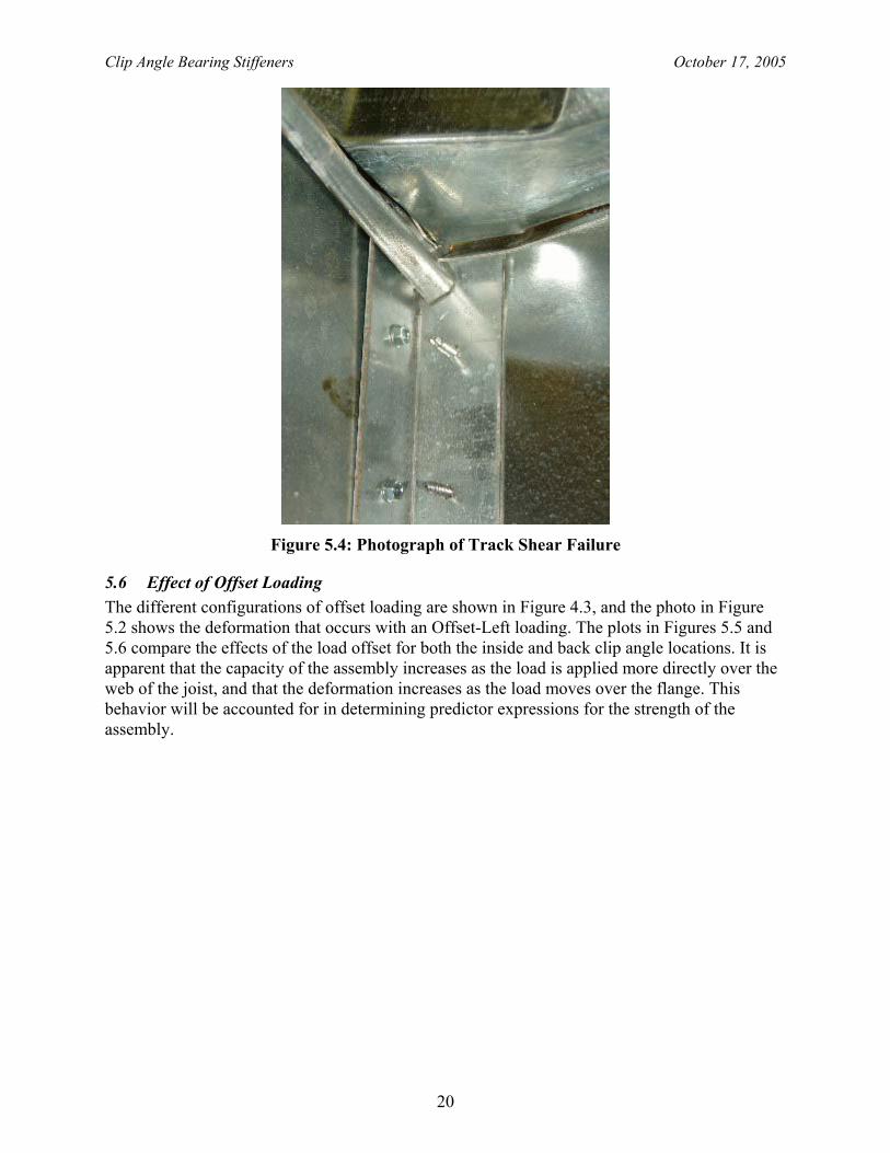
Figure 5.4: Photograph of Track Shear Failure
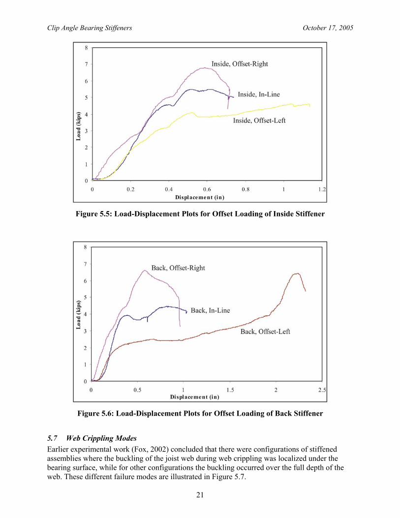
5.6 Effect of Offset Loading The different configurations of offset loading are shown in Figure 4.3, and the photo in Figure 5.2 shows the deformation that occurs with an Offset-Left loading. The plots in Figures 5.5 and 5.6 compare the effects of the load offset for both the inside and back clip angle locations. It is apparent that the capacity of the assembly increases as the load is applied more directly over the web of the joist, and that the deformation increases as the load moves over the flange. This behavior will be accounted for in determining predictor expressions for the strength of the assembly.
Clip Angle Bearing Stiffeners October 17, 2005
21
Figure 5.5: Load-Displacement Plots for Offset Loading of Inside Stiffener
Figure 5.6: Load-Displacement Plots for Offset Loading of Back Stiffener
5.7 Web Crippling Modes Earlier experimental work (Fox, 2002) concluded that there were configurations of stiffened assemblies where the buckling of the joist web during web crippling was localized under the bearing surface, while for other configurations the buckling occurred over the full depth of the web. These different failure modes are illustrated in Figure 5.7.
Clip Angle Bearing Stiffeners October 17, 2005
22
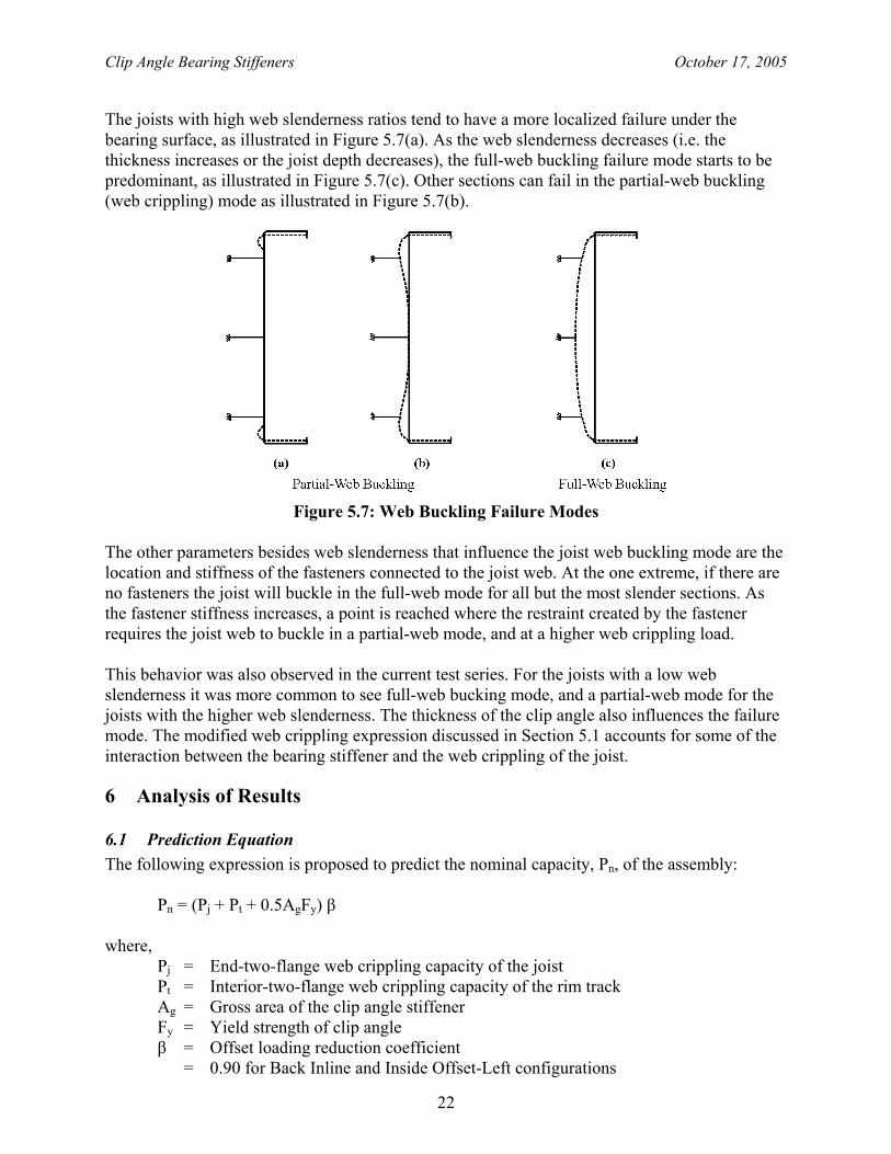
The joists with high web slenderness ratios tend to have a more localized failure under the bearing surface, as illustrated in Figure 5.7(a). As the web slenderness decreases (i.e. the thickness increases or the joist depth decreases), the full-web buckling failure mode starts to be predominant, as illustrated in Figure 5.7(c). Other sections can fail in the partial-web buckling (web crippling) mode as illustrated in Figure 5.7(b).
Figure 5.7: Web Buckling Failure Modes
The other parameters besides web slenderness that influence the joist web buckling mode are the location and stiffness of the fasteners connected to the joist web. At the one extreme, if there are no fasteners the joist will buckle in the full-web mode for all but the most slender sections. As the fastener stiffness increases, a point is reached where the restraint created by the fastener requires the joist web to buckle in a partial-web mode, and at a higher web crippling load. This behavior was also observed in the current test series. For the joists with a low web slenderness it was more common to see full-web bucking mode, and a partial-web mode for the joists with the higher web slenderness. The thickness of the clip angle also influences the failure mode. The modified web crippling expression discussed in Section 5.1 accounts for some of the interaction between the bearing stiffener and the web crippling of the joist.
6 Analysis of Results
6.1 Prediction Equation The following expression is proposed to predict the nominal capacity, Pn, of the assembly:
Pn = (Pj + Pt + 0.5AgFy) β where, Pj = End-two-flange web crippling capacity of the joist Pt = Interior-two-flange web crippling capacity of the rim track Ag = Gross area of the clip angle stiffener Fy = Yield strength of clip angle β = Offset loading reduction coefficient = 0.90 for Back Inline and Inside Offset-Left configurations
Clip Angle Bearing Stiffeners October 17, 2005
23
= 0.50 for Back Offset-Left configuration = 1.0 for all other cases The above equation is valid within the following range of parameters:
Screws #8 minimum for clip angle thicknesses up to 54 mil, and #10 minimum for thicker angles
Floor Joist and Rim Track Thickness: 43 mil to 103 mil Design Yield Strength: 33 ksi and 50 ksi depending on material thickness Nominal Depth: 8 inch to 12 inch Bearing Width: 1-1/2 inch Clip Angle Thickness: 30 mil to 75 mil
(Note that the 103 mil clip angle is excluded) Design Yield Strength: 33 ksi and 50 ksi depending on material thickness
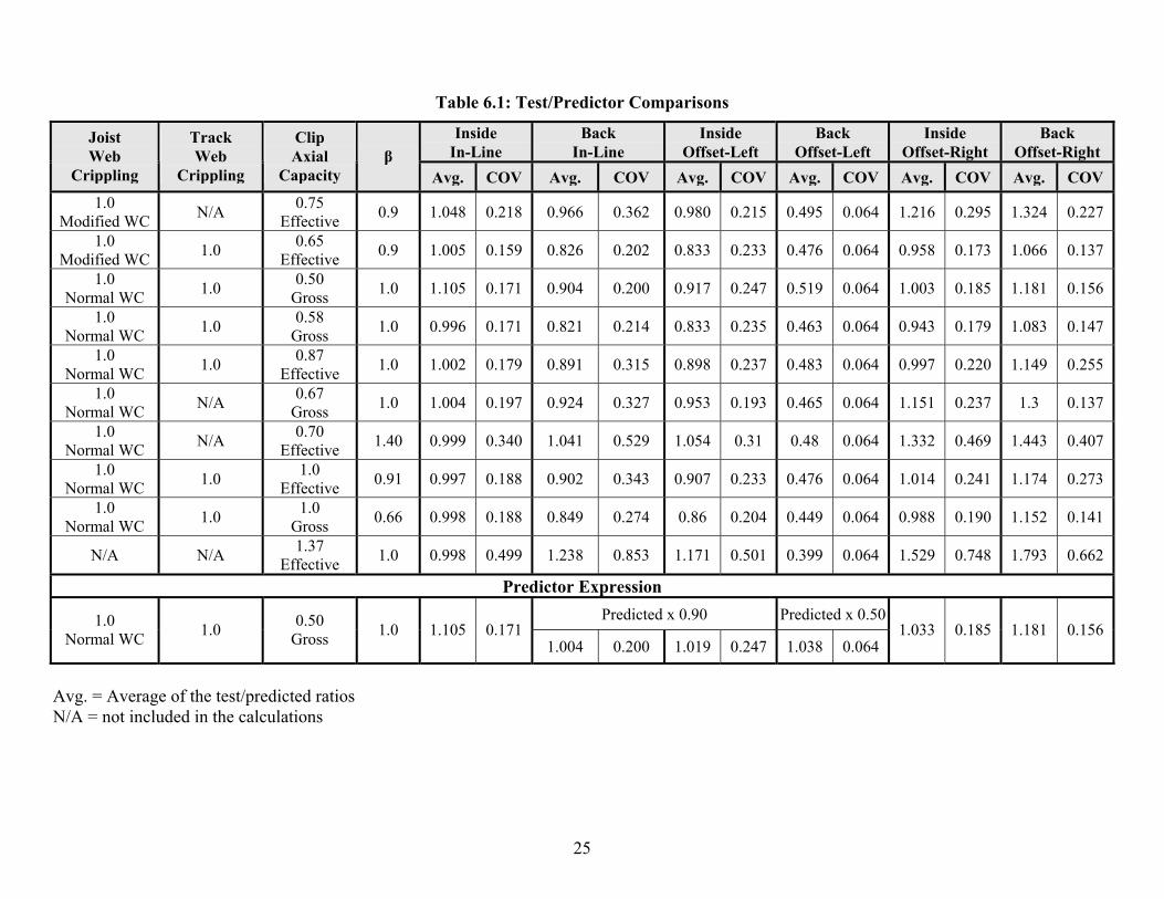
Stiffener Length: Not less than 3/8 inch shorter than the joist depth Size: 1-1/2 inch by 1-1/2 inch angle Screws: At least three screws connecting each leg equally spaced The recommended method was selected after considering a number of alternatives. Listed in Table 6.1 is a summary of the various methods considered. The following is a discussion of the issues considered during the analysis process.
• The failure mode involved the web crippling of the joist and rim track combined with the capacity of the clip angle subject to axial compression. The numbers in the first three columns of Table 6.1 correspond to the percentage of the component capacities that were used in the analysis. For example, the trial listed in Row 2 included 100% of the modified joist web crippling capacity, none of the rim track web crippling capacity, and 75% of the axial capacity of the clip angle based on the effective area.
• There is a complex interaction between the deformation of the assembly and the axial load being transferred into the clip angle such that it is impossible to determine the exact distribution of forces. The clip angle acts as a short compression member, so to simplify the analysis it was assumed that the angle was subject to a uniform compressive stress. The effective area of the angle was computed on this basis.
• Predictor equations were considered based on a reduced stress on the gross area as well as the yield stress on an effective area of the clip angle. Using the gross area of the angle makes the calculation process much easier. Given the variability in the results, any increased accuracy that may result from using the effective area does not justify the added complexity of calculation.
• The modified web crippling expression reduced the variance in the predictor equation compared to using the standard web crippling expression. However, the reduced scatter was not deemed enough to justify the added complexity of incorporating the modified web crippling expression.
• There was no relationship observed when the test/predicted ratios were plotted against both the joist slenderness ratio and the joist thickness. These variables could not be used as additional parameters in the predictor expression to reduce scatter.
Clip Angle Bearing Stiffeners October 17, 2005
24
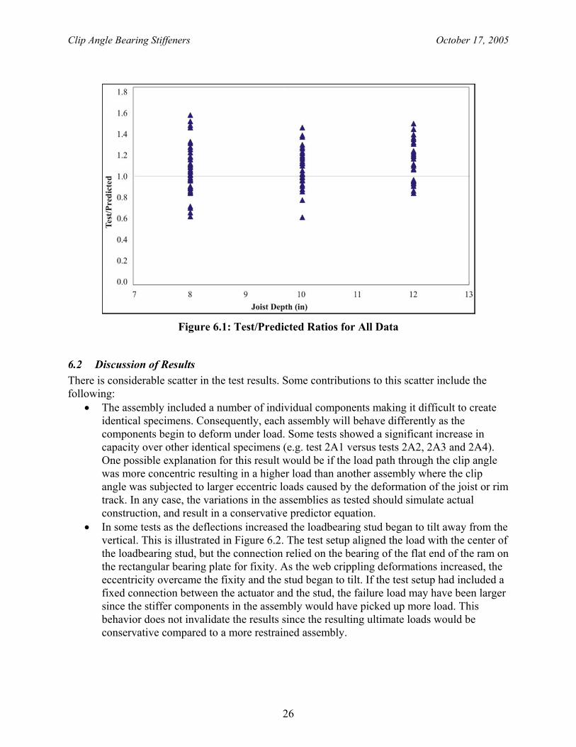
• Shown in Figure 6.1 are the plots of the test/predicted ratios versus the joist depth for all data using the proposed prediction equation.
• The assemblies with the 103 mil thick clip angles experienced a number of other problems not occurring with the thinner angles (e.g. screw shear and track punch-through). Given this behaviour, it was deemed prudent to limit application of the proposed predictor equation to 75 mil thick clip angles and thinner as indicated.
25
Table 6.1: Test/Predictor Comparisons
Inside In-Line
Back In-Line
Inside Offset-Left
Back Offset-Left
Inside Offset-Right
Back Offset-Right
Joist Web
Crippling
Track Web
Crippling
Clip Axial
Capacity β
Avg. COV Avg. COV Avg. COV Avg. COV Avg. COV Avg. COV 1.0
Modified WC N/A 0.75 Effective 0.9 1.048 0.218 0.966 0.362 0.980 0.215 0.495 0.064 1.216 0.295 1.324 0.227
1.0 Modified WC 1.0 0.65
Effective 0.9 1.005 0.159 0.826 0.202 0.833 0.233 0.476 0.064 0.958 0.173 1.066 0.137
1.0 Normal WC 1.0 0.50
Gross 1.0 1.105 0.171 0.904 0.200 0.917 0.247 0.519 0.064 1.003 0.185 1.181 0.156
1.0 Normal WC 1.0 0.58
Gross 1.0 0.996 0.171 0.821 0.214 0.833 0.235 0.463 0.064 0.943 0.179 1.083 0.147
1.0 Normal WC 1.0 0.87
Effective 1.0 1.002 0.179 0.891 0.315 0.898 0.237 0.483 0.064 0.997 0.220 1.149 0.255
1.0 Normal WC N/A 0.67
Gross 1.0 1.004 0.197 0.924 0.327 0.953 0.193 0.465 0.064 1.151 0.237 1.3 0.137
1.0 Normal WC N/A 0.70
Effective 1.40 0.999 0.340 1.041 0.529 1.054 0.31 0.48 0.064 1.332 0.469 1.443 0.407
1.0 Normal WC 1.0 1.0
Effective 0.91 0.997 0.188 0.902 0.343 0.907 0.233 0.476 0.064 1.014 0.241 1.174 0.273
1.0 Normal WC 1.0 1.0
Gross 0.66 0.998 0.188 0.849 0.274 0.86 0.204 0.449 0.064 0.988 0.190 1.152 0.141
N/A N/A 1.37 Effective 1.0 0.998 0.499 1.238 0.853 1.171 0.501 0.399 0.064 1.529 0.748 1.793 0.662
Predictor Expression Predicted x 0.90 Predicted x 0.501.0
Normal WC 1.0 0.50 Gross 1.0 1.105 0.171
1.004 0.200 1.019 0.247 1.038 0.064 1.033 0.185 1.181 0.156
Avg. = Average of the test/predicted ratios N/A = not included in the calculations
Clip Angle Bearing Stiffeners October 17, 2005
26
Figure 6.1: Test/Predicted Ratios for All Data
6.2 Discussion of Results There is considerable scatter in the test results. Some contributions to this scatter include the following:
• The assembly included a number of individual components making it difficult to create identical specimens. Consequently, each assembly will behave differently as the components begin to deform under load. Some tests showed a significant increase in capacity over other identical specimens (e.g. test 2A1 versus tests 2A2, 2A3 and 2A4). One possible explanation for this result would be if the load path through the clip angle was more concentric resulting in a higher load than another assembly where the clip angle was subjected to larger eccentric loads caused by the deformation of the joist or rim track. In any case, the variations in the assemblies as tested should simulate actual construction, and result in a conservative predictor equation.
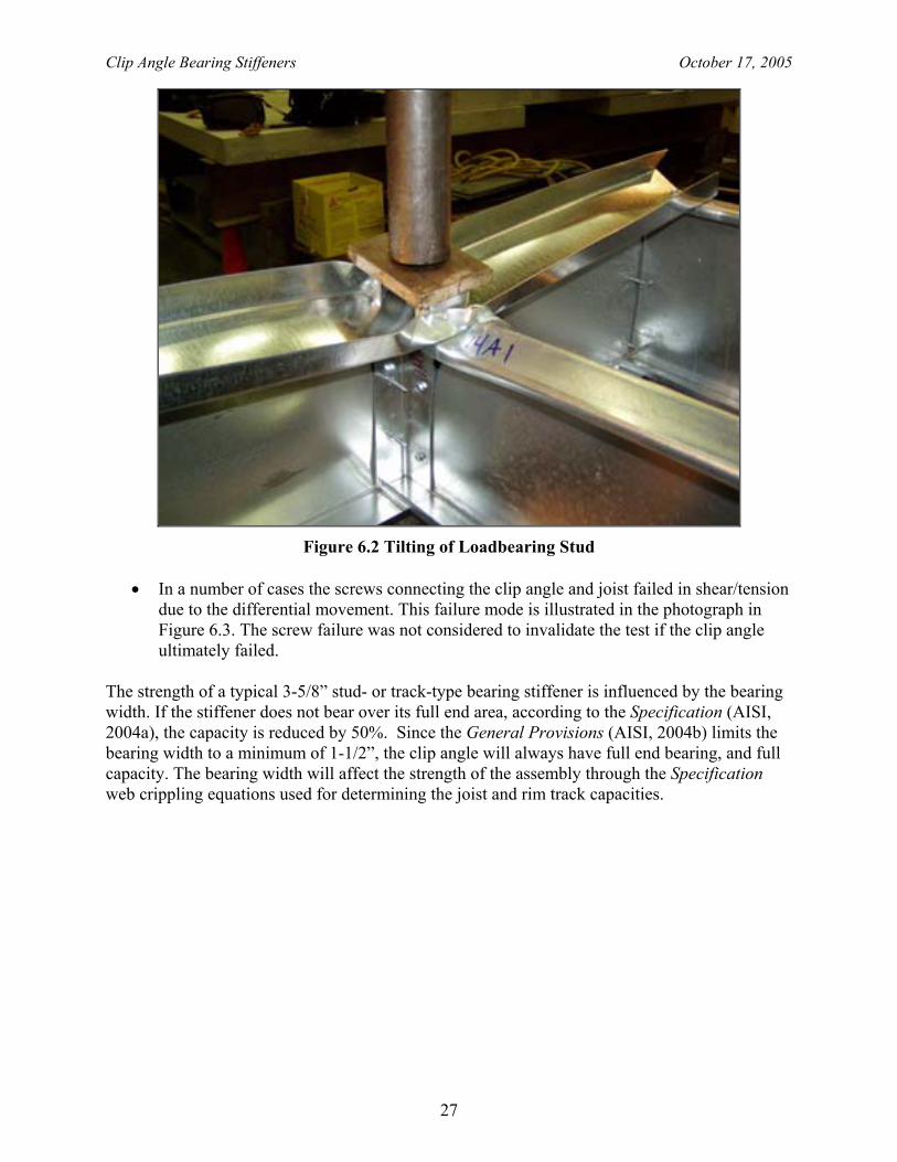
• In some tests as the deflections increased the loadbearing stud began to tilt away from the vertical. This is illustrated in Figure 6.2. The test setup aligned the load with the center of the loadbearing stud, but the connection relied on the bearing of the flat end of the ram on the rectangular bearing plate for fixity. As the web crippling deformations increased, the eccentricity overcame the fixity and the stud began to tilt. If the test setup had included a fixed connection between the actuator and the stud, the failure load may have been larger since the stiffer components in the assembly would have picked up more load. This behavior does not invalidate the results since the resulting ultimate loads would be conservative compared to a more restrained assembly.
Clip Angle Bearing Stiffeners October 17, 2005
27
Figure 6.2 Tilting of Loadbearing Stud
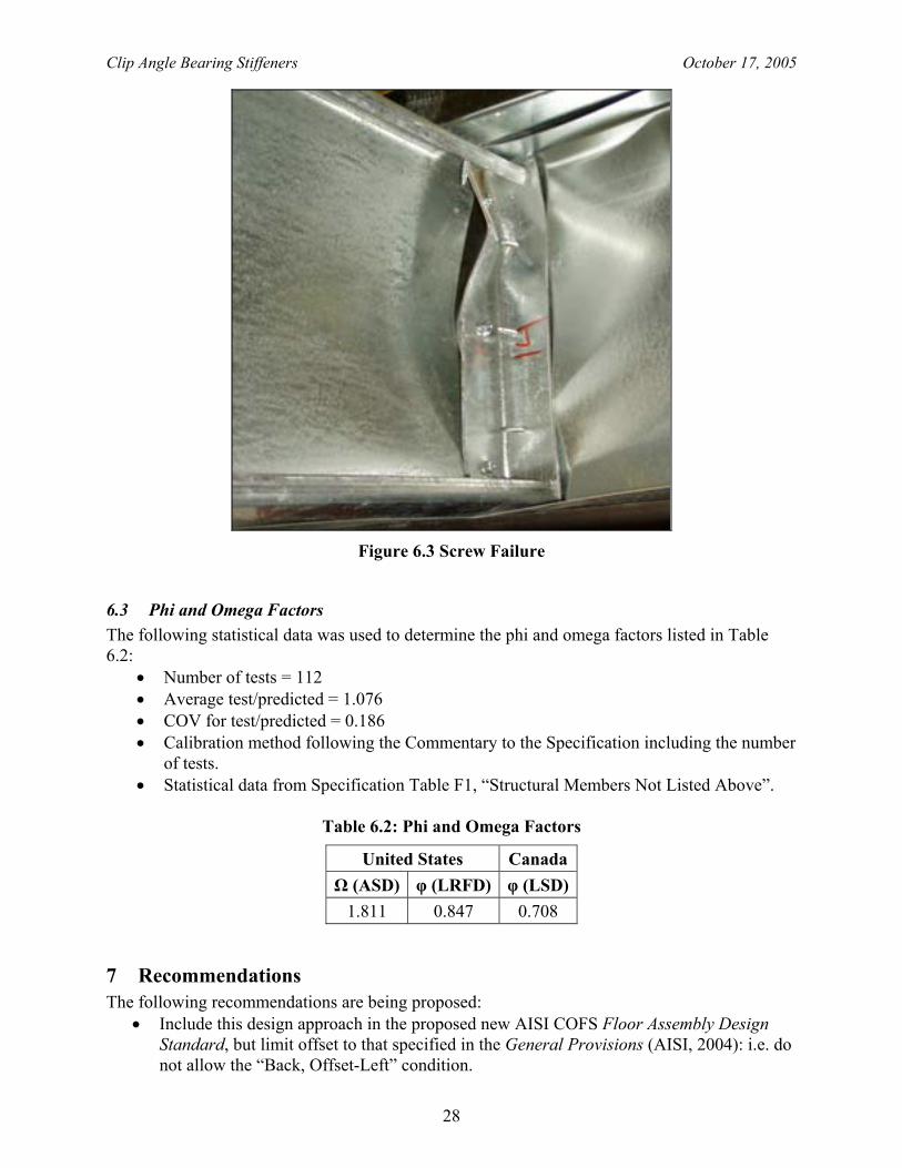
• In a number of cases the screws connecting the clip angle and joist failed in shear/tension
due to the differential movement. This failure mode is illustrated in the photograph in Figure 6.3. The screw failure was not considered to invalidate the test if the clip angle ultimately failed.
The strength of a typical 3-5/8” stud- or track-type bearing stiffener is influenced by the bearing width. If the stiffener does not bear over its full end area, according to the Specification (AISI, 2004a), the capacity is reduced by 50%. Since the General Provisions (AISI, 2004b) limits the bearing width to a minimum of 1-1/2”, the clip angle will always have full end bearing, and full capacity. The bearing width will affect the strength of the assembly through the Specification web crippling equations used for determining the joist and rim track capacities.
Clip Angle Bearing Stiffeners October 17, 2005
28
Figure 6.3 Screw Failure
6.3 Phi and Omega Factors The following statistical data was used to determine the phi and omega factors listed in Table 6.2:
• Number of tests = 112 • Average test/predicted = 1.076 • COV for test/predicted = 0.186 • Calibration method following the Commentary to the Specification including the number
of tests. • Statistical data from Specification Table F1, “Structural Members Not Listed Above”.
Table 6.2: Phi and Omega Factors
United States Canada Ω (ASD) φ (LRFD) φ (LSD)
1.811 0.847 0.708
7 Recommendations The following recommendations are being proposed:
• Include this design approach in the proposed new AISI COFS Floor Assembly Design Standard, but limit offset to that specified in the General Provisions (AISI, 2004): i.e. do not allow the “Back, Offset-Left” condition.
Clip Angle Bearing Stiffeners October 17, 2005
29
• In the Commentary to the new Standard include a reference to the General Provisions Commentary for the minimum screw size based on material thickness.
• Limit the applicability as indicated in Section 6.1. • Consider reducing the predictor equation by 90% to recognize the scatter in the data. This
would then allow the predictor equation to be applied without the 90% reduction factor for the two offset conditions.
• Additional testing is always advisable to verify the extension of this design method to other thicknesses of rim track, and to provide additional data for the offset conditions.
8 Acknowledgment The Steel Framing Alliance and the Steel Stud Manufacturers Association must be acknowledged for financially supporting this project, and the AISI Committee on Framing Standards for their input and guidance. Undergraduate students at the University of Waterloo, Ed McGriskin, Mechelle Pope and Steve Routledge are thanked for their assistance in carrying out the tests.
9 References 1. AISI (2004a). North American Specification for the Design of Cold-Formed Steel Structural
Members with 2004 Supplement. American Iron and Steel Institute, Washington, D.C., USA.
2. AISI (2001). Standard for Cold-Formed Steel Framing – Prescriptive Method for One and Two Family Dwellings. American Iron and Steel Institute, Washington, D.C.
3. AISI (2004b). Standard for Cold-Formed Steel Framing – General Provisions. American Iron and Steel Institute, Washington, D.C.
4. Fox, S.R. (2002). Bearing Stiffeners in Cold Formed Steel Floor C-Sections. PhD Thesis. University of Waterloo. Waterloo, Ontario, Canada.
5. Fox, S.R. (2003). The Strength of Stiffened Cold Formed Steel Floor Joist Assemblies with Offset Loading. American Iron and Steel Institute, Washington, D.C., USA.
6. Fox, S.R. and Schuster, R.M. (2002). Bearing Stiffeners in Cold Formed Steel C-Sections. American Iron and Steel Institute, Washington, D.C., USA.
7. Fox, S.R. and Schuster, R.M. (2003). “Design of Cold-Formed Steel Bearing Stiffeners”, Proceedings of the International Conference on Advances in Structures. Sydney, Australia. A.A. Balkema Publishers. Pp 351-356.
8. House et. al. (2002). Clip Angles as Bearing Stiffeners in Cold Formed Steel Floor Joists. Canadian Cold Formed Steel Research Group unpublished report. University of Waterloo. Waterloo, Ontario, Canada.
1201 15th Street, NW
Suite 320
Washington, DC 20005
www.steelframing.org
American Iron and Steel Institute
1140 Connecticut Avenue, NW
Suite 705
Washington, DC 20036
www.steel.org
Re
se
arc
h R
ep
ort
RP
-05
-6


![[Cbca] steel framing - engenharia](https://img.pdfslide.us/doc/110x75/55854378d8b42a5e018b4fc6/cbca-steel-framing-engenharia.jpg)