Embed Size (px)
Citation preview

Research On The Regional Division Of Free Surface Machining Based On K-Means Clustering Algorithm
Xianlong Han
Engineering Training Center, Beihua University, Jilin, 132021,China email: [email protected]
Keywords: K-means; Free surface; region division
Abstract. For automobile covering parts of the die size and surface between adjacent points are frequent change of curvature and variation amplitude is bigger, the K-means clustering algorithm, to sub surface boundary region data parameterization, and ultimately realize the surface area. It is at this time, complex parametric curved surface that is composed of a series of easy combination of mechanical processing of simple and small surface and, for follow-up with same shape feature or a similar sub surface can be used similar parameters for milling.
Introduction When the free surface is processed, the machining precision and machining efficiency are mainly considered. But in automobile covering pieces of this large mold machining process existing problems, on the one hand is the working space and the processing precision, stiffness of the contradictions, on the other hand in checking collision and deal with related issues such as on the line of intersection with the boundary on will consume a certain amount of time, this will lead to processing efficiency dropped significantly. When the curvature of the free surface is changed greatly, the curvature of the contact between the tool and the machining surface is constantly changing, so that the speed of the cutter line is changed, and the machining precision can be changed. Thus it may be known, to ensure machining precision toward the surface machining to partition the domain processing, recognition of each sub surface with the same or similar characteristics, then according to the principle of cluster will classify these surfaces.
Preliminary Division Of The Processing Area Through the analysis of surface characteristics, we can know that the curvature of any point on the surface will not change because of the position and direction of the surface, and it is not related to the expression of the surface parameters, which is the inherent characteristic of the surface. Therefore, the curvature of the surface and the distribution of the curvature of the surface is divided into the region, does not change with the position and direction of the surface. Firstly complex surface region as a whole preliminary into three categories, respectively, convex, concave and double curved surface, so after the surface nodes of a suite rate divided surface shape. According to the actual needs, in this paper, based on the Guass curvature and Mean curvature{K, H}to distinguish the surface shape, the corresponding Table 1 and the local area of the curve as shown in Figure 1.
Table 1. Surface shape relationship with geometric parameters K,H Interval value Point type Approximate surface
K>0, H>0 Ellipse Concave K>0, H<0 Ellipse Convex
K<0 Hyperbolic Hyperbolic K=0, H>0 Parabolic Concave parabolic K=0, H=0 Flat plane K=0, H<0 Parabolic Convex parabolic
7th International Conference on Mechatronics, Control and Materials (ICMCM 2016)
Copyright © 2016, the Authors. Published by Atlantis Press. This is an open access article under the CC BY-NC license (http://creativecommons.org/licenses/by-nc/4.0/).
Advances in Engineering Research, volume 104
312
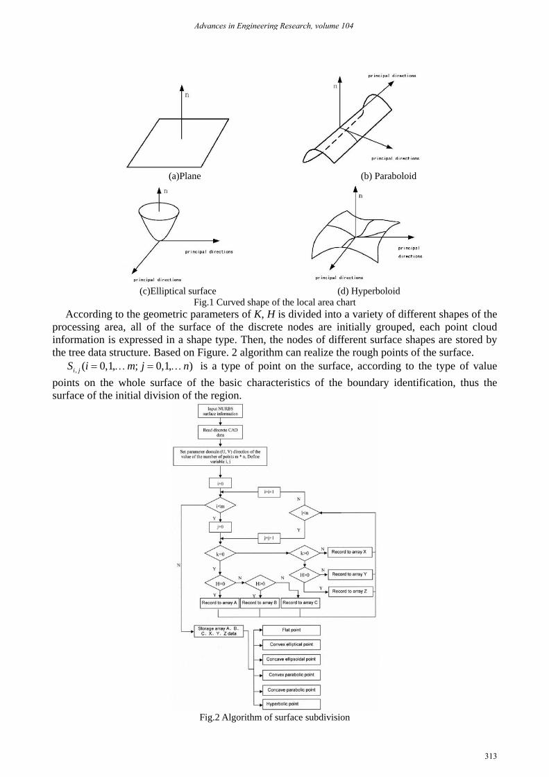
(a)Plane (b) Paraboloid
(c)Elliptical surface (d) Hyperboloid
Fig.1 Curved shape of the local area chart According to the geometric parameters of K, H is divided into a variety of different shapes of the
processing area, all of the surface of the discrete nodes are initially grouped, each point cloud information is expressed in a shape type. Then, the nodes of different surface shapes are stored by the tree data structure. Based on Figure. 2 algorithm can realize the rough points of the surface.
, ( 0,1, ; 0,1, )= … = …i jS i m j n is a type of point on the surface, according to the type of value points on the whole surface of the basic characteristics of the boundary identification, thus the surface of the initial division of the region.
Fig.2 Algorithm of surface subdivision
Advances in Engineering Research, volume 104
313
Accurate Division of the Region In practice, although the rough dividing surface is improved, the effect is not obvious. Therefore, in this paper, by using the -means K clustering algorithm and the median sharing method, the rough surface is divided into the sub surface, and the number of sub surface and the center position of the sub surface are determined. Finally, the boundary curves between the sub surfaces are obtained by using the boundary region data, and the subdivision surface is realized.
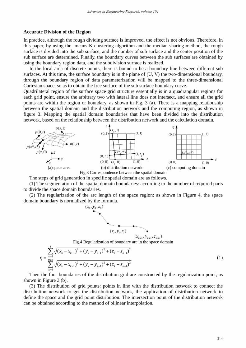
In the local area of discrete points, there is bound to be a boundary line between different sub surfaces. At this time, the surface boundary is in the plane of (U, V) the two-dimensional boundary, through the boundary region of data parameterization will be mapped to the three-dimensional Cartesian space, so as to obtain the free surface of the sub surface boundary curve. Quadrilateral region of the surface space grid structure essentially is in a quadrangular regions for each grid point, ensure the arbitrary two with lateral line does not intersect, and ensure all the grid points are within the region or boundary, as shown in Fig. 3 (a). There is a mapping relationship between the spatial domain and the distribution network and the computing region, as shown in figure 3. Mapping the spatial domain boundaries that have been divided into the distribution network, based on the relationship between the distribution network and the calculation domain.
(a)space area (b) distribution network (c) computing domain
Fig.3 Correspondence between the spatial domain The steps of grid generation in specific spatial domain are as follows. (1) The segmentation of the spatial domain boundaries: according to the number of required parts
to divide the space domain boundaries. (2) The regularization of the arc length of the space region: as shown in Figure 4, the space
domain boundary is normalized by the formula.
Fig.4 Regularization of boundary arc in the space domain
2 2 21 1 1
1max
2 2 21 1 1
1
( ) ( ) ( )
( ) ( ) ( )
i
k k k k k kk
i
k k k k k kk
x x y y z zr
x x y y z z
− − −=
− − −=
− + − + −=
− + − + −
∑
∑ (1)
Then the four boundaries of the distribution grid are constructed by the regularization point, as shown in Figure 3 (b).
(3) The distribution of grid points: points in line with the distribution network to connect the distribution network to get the distribution network, the application of distribution network to define the space and the grid point distribution. The intersection point of the distribution network can be obtained according to the method of bilinear interpolation.
Advances in Engineering Research, volume 104
314
* 1 1 2 1
2 1 2 1
* 1 1 2 1
2 1 2 1
( )1 ( )( )
( )1 ( )( )
s t s sst t s s
t s t ttt t s s
+ − = − − − + − = − − −
(2)
(4) the curve of the spatial region: through the distribution of grid point coordinates, with the Lagrange, Hermite, Bezier, B-Spline and other mathematical expressions fitting curve.
Application Examples Of Algorithm In order to verify the correctness of the proposed method in the paper, we take a parametric surface with free surface feature as an example, as shown in Figure 5.
2
2
2 2 2 2 2 2
40 35 558 18
6( ) 4 34 4 14 50 25 6
x v vy u uz u v u v uv u v uv u v
= − + +
= − + = + − + + − − + +
(3)
[ ] [ ]0,1 , 0,1u v⊆ ⊆ (4) First, the parameters of the surface with appropriate density along the parameters of the V and u
direction of the discrete, discrete generated after the mesh vertex as a discrete value point. Then, the coordinates of discrete points are extracted, which is the basis for the calculation of the geometric parameters of the following surfaces. According to the table 1 Analysis of the shape of the local surface and the shape of the storage up, get as shown in Figure 6 of the initial partition graph, in which the red circle represents a convex oval face, LAN-STAR.
Fig.5 A parametric surface Fig.6 The preliminary division
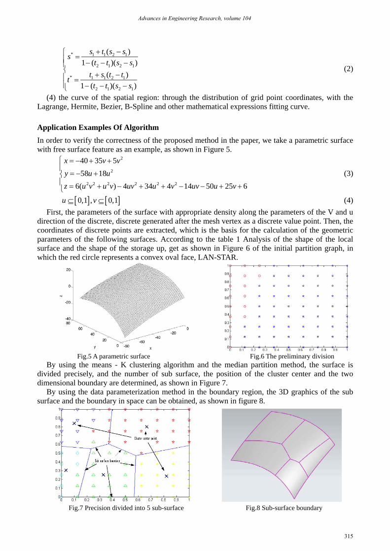
By using the means - K clustering algorithm and the median partition method, the surface is divided precisely, and the number of sub surface, the position of the cluster center and the two dimensional boundary are determined, as shown in Figure 7.
By using the data parameterization method in the boundary region, the 3D graphics of the sub surface and the boundary in space can be obtained, as shown in figure 8.
Fig.7 Precision divided into 5 sub-surface Fig.8 Sub-surface boundary
Advances in Engineering Research, volume 104
315
The Results Of The Experiment Figure 9 is the tool path planning method which is proposed in this paper.
Fig.9 Proposed method to generate tool path
Through the numerical control programming in Powermill, the experimental work piece as shown in Figure 10 after semi finish machining, the method proposed in this paper is corresponding to the measurement of the region containing the joint phenomenon.
Fig.10 After semi-finishing the experimental workpieces
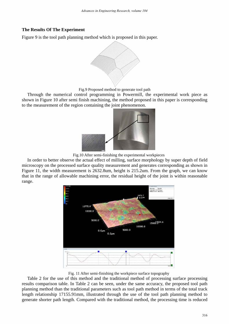
In order to better observe the actual effect of milling, surface morphology by super depth of field microscopy on the processed surface quality measurement and generates corresponding as shown in Figure 11, the width measurement is 2632.8um, height is 215.2um. From the graph, we can know that in the range of allowable machining error, the residual height of the joint is within reasonable range.
Fig. 11 After semi-finishing the workpiece surface topography
Table 2 for the use of this method and the traditional method of processing surface processing results comparison table. In Table 2 can be seen, under the same accuracy, the proposed tool path planning method than the traditional parameters such as tool path method in terms of the total track length relationship 17155.91mm, illustrated through the use of the tool path planning method to generate shorter path length. Compared with the traditional method, the processing time is reduced
Advances in Engineering Research, volume 104
316

by 27.15%, so that the machining efficiency can be improved effectively. Table 2 Comparison of the processing results
path length(mm) Average operation time(s)
Traditional parameter tool path method 54479.8 3366
The method proposed in this paper
9961.76
2452 8221.29 3719.63 9367.38 6053.93
Reduce total length 17155.91 914 Reduction ratio 31.49% 27.15%
Reference
[1] P. Broomhead, M. Edkins, Generation of NC data at the machine tool for the manufacture of free-form surfaces. International Journal of Production Research. 1986,24 (1):1-14
[2] Z.C. Chen, Z. Dong, G.W. Vickers. Steepest-directed tool path in 3-axis CNC machining-the most efficient machining scheme and its mathematical proof, in: Proceedings of the ASME 2001 Design Engineering Technical Conferences and Computers and Information in Engineering Conference. 9-12 September 2001, Pittsburgh, PA, USA.
[3] S. Bedi, S. Gravelle, machining complex 765YH. Chensurfaces . Principal curvature alignment technique for Transactions of the ASME. 1997,119:756
[4] Saito T, Takahashi T. NC machining with G-buffer method[J]. Computer Graphics, 1991, 25(4): 207-216.
[5]Choi B,Ko K. C-space based LAPP algorithm for freeform die-cavity machining[J]. Computer-Aided Design, 2003, 35(2): 179-189.
[6] Farouki R. The approximation of non-degenerate offset surfaces[J].Computer Aided Geometric Design, 1986, 3(1): 15-43
[7] Pessoles X, Landon Y, Rubio W. Kinematic modelling of a 3-axis NC machine tool in linear and circular interpolation. Int J Adv Manuf Technol,2010,47:639- 655.
Advances in Engineering Research, volume 104
317