Embed Size (px)
Citation preview
ORIGINAL RESEARCH Open Access
Research on power control strategy ofhousehold-level electric power routerbased on hybrid energy storage droopcontrolKun Huang1,2, Yanman Li1,2, Xiaoyan Zhang1,2, Lei Liu3, Yanbin Zhu4* and Xin Meng4
Abstract
In the light of user-side energy power control requirements, a power control strategy for a household-level EPRbased on HES droop control is proposed, focusing on the on-grid, off-grid and seamless switching process. Thesystem operating states are divided based on the DC bus voltage information with one converter used as a slackterminal to stabilize the DC bus voltage and the other converters as power terminals. In the on-grid mode, the GCCand the HES are used as the main control unit to achieve on-grid stable operation, whereas in the off-grid mode,the PV, HES and LC are used as the main control unit at different voltages to achieve stable operation of the islandnetwork. Finally, a DC MG system based on a household-level EPR is developed using the PSCAD / EMTDCsimulation platform and the results show that the control strategy can effectively adjust the output of each subunitand maintain the stability of the DC bus voltage.
Keywords: Household-level electric power router, Hybrid energy storage, Droop control, On-grid mode, Off-gridmode
1 IntroductionThe existing large power grid will remain the main partof the future energy Internet [5, 26]. Despite the diverseforms of energy, electrical energy has great advantagesin terms of transmission efficiency and economy. Elec-trical energy can also be easily converted to other forms(cold or hot) of energy. Therefore, the EPR as an energyconversion device has received increasing attention inindustry and academia [22].At present, the traditional distribution network is
facing diverse problems and challenges. The fragility ofthe distribution network structure does not provide suf-ficient support to the access of a large amount of renew-able energy, while the problems of poor node autonomy
and low degree of freedom are becoming more serious[42]. In addition, distributed generations have the char-acteristics of high uncertainty, high uncontrollability,wide distribution, remote location, harsh operatingenvironment, low equipment reliability, and largeoperational and maintenance workload [27]. The powersystem is also developing towards a new stage of co-ordinated and optimized “source-network-load-storage”operation, which will become the core of the future en-ergy internet [1, 6]. In the future, the power system willbe formed by bottom-up autonomous units of electricalenergy through peer-to-peer interconnection. Such open,interconnected, peer-to-peer and shared power systemsrequire a high degree of integration of information andelectrical energy, and precise, continuous, fast, and flex-ible control methods. The traditional grid-connected dis-tributed power generation devices cannot realize thescheduling and independent management of the user’s
© The Author(s). 2021 Open Access This article is licensed under a Creative Commons Attribution 4.0 International License,which permits use, sharing, adaptation, distribution and reproduction in any medium or format, as long as you giveappropriate credit to the original author(s) and the source, provide a link to the Creative Commons licence, and indicate ifchanges were made. The images or other third party material in this article are included in the article's Creative Commonslicence, unless indicated otherwise in a credit line to the material. If material is not included in the article's Creative Commonslicence and your intended use is not permitted by statutory regulation or exceeds the permitted use, you will need to obtainpermission directly from the copyright holder. To view a copy of this licence, visit http://creativecommons.org/licenses/by/4.0/.
* Correspondence: [email protected] Laboratory of Smart Grid of Ministry of Education, Tianjin University,Tianjin 300072, ChinaFull list of author information is available at the end of the article
Protection and Control ofModern Power Systems
Huang et al. Protection and Control of Modern Power Systems (2021) 6:13 https://doi.org/10.1186/s41601-021-00190-2
electric energy, while the user side lacks equipment forimplementing electric energy management and control.With this as background, the concept of “electric powerrouter” based on power electronics technology has cometo the fore [7].As a key device of the energy Internet, current re-
search on the power router is mainly focused on elec-trical topology and control strategy. In terms ofelectrical topology, references [8, 23, 43] propose athree-port DC converter with simple structure, flex-ible control, and easy implementation. However, itsexpansion is limited. In [39], a four-port converterwith three input ports and one output port is pro-posed for application in the new energy power gener-ation. It has high switch utilization, simple topologyand high energy density, but the number of ports islimited and energy cannot flow in both directions.Four-port and three-port DC-DC converters withmulti-winding high-frequency isolation transformersand high power density are proposed in [19, 30], re-spectively. The output of multiple voltage levels is re-alized through a multi-winding transformer. However,such converters require complicated parameter adjust-ment and have high production cost. Reference [28]describes a large-capacity MPC topology with an ACor DC bus, in which each port is connected with anAC or DC bus and bidirectional flow of energy canbe realized.The electric power router has evolved from the
structure of a power electronic transformer, while its de-velopment process has gone through several stages ofhigh-frequency transformer, fully electronic transformer,intelligent high-frequency transformer, high-voltagehigh-frequency transformer, and multi-port routingtransformer. At present, an electric power router canimplement intelligent management and control of dis-tributed power generation equipment, energy storageand the existing power network, and realize an electricalenergy dispatch control function.The power router based on the multi-port routing
transformer structure is generally used in small andmedium power applications, and is suitable for powerconversion and control between low-voltage power dis-tribution system on the user side and household distrib-uted power supply. The electrical topology of theexisting power routers is largely mature, but research onthe control strategy is urgently needed. This paperadopts a multi-port routing and transformer powerrouter topology, which not only achieves the basic re-quirements such as voltage conversion, reliable electricalisolation, independent port design, and two-way energyflow, but also reduces equipment costs, improves effi-ciency, reduces size, and expands the flexibility of portuse [9, 20, 24, 46].
A lot of research has been carried out on the powercontrol strategy of an EPR. In [21], a coordinatedcontrol strategy based on a DC bus voltage signal isused, while the operation target and power distribu-tion of the system are realized by using the cooper-ation of threshold voltage and droop control. In [25],the DC bus voltage is used to distinguish betweenon-grid and off-grid modes of operation, and the DC-AC converter and energy storage unit connected tothe grid are used to maintain the bus voltage. How-ever, in the on-grid mode, the energy storage unit isalways in a standby state with low utilization rate. In[14, 34], the droop control strategy is used to ensurea smooth transition of the DC bus voltage betweendifferent levels. However, since the working curve ofeach unit in the DC MG has to be predetermined,the flexibility of the system is low.Most existing literature discusses the operation and
control of a DC MG in island mode. Because of the lackof backup, when energy surplus or shortage occurs, sys-tem stability is poor and the application is limited. Stud-ies on the operating status under direct grid connectionare usually under the support of a large power grid, sothe coordinated control of PV and other micro powersources and energy storage is ignored, and the influenceof factors for energy storage batteries such as remainingcapacity cannot be fully considered, causing batterydamage and harm.In summary, although the current technical specifica-
tions of the electrical energy router standard have notbeen uniformly formulated [10, 17, 29, 32, 37], a lot ofwork has been done on topology optimization and keytechnology analysis. This paper comprehensively con-siders the operating characteristics of the off-grid oper-ation mode and integrates the converter controlstrategies into a household-level electric power router.Taking home user applications as the main operatingscenario, two on-grid and 6 off-grid operating modes aredesigned. Various application scenarios are proposed,and the proposed control strategy ensures that the sys-tem can smoothly switch between the various workingmodes, and realize stable and reliable operation of theuser system and the efficient use of energy.The organization of the rest of the paper is as fol-
lows. The topology of a household-level electrical en-ergy routing device is introduced in Section II andaccording to the system DC bus voltage information,the corresponding system power control strategy isproposed in Section III. In Section IV, a systemmodel containing PV, hybrid energy storage, grid-connected converters, AC and DC loads is developedon the PSCAD / EMTDC simulation platform to ver-ify the effectiveness of the proposed control strategy.Finally, Section V draws the conclusions.
Huang et al. Protection and Control of Modern Power Systems (2021) 6:13 Page 2 of 13
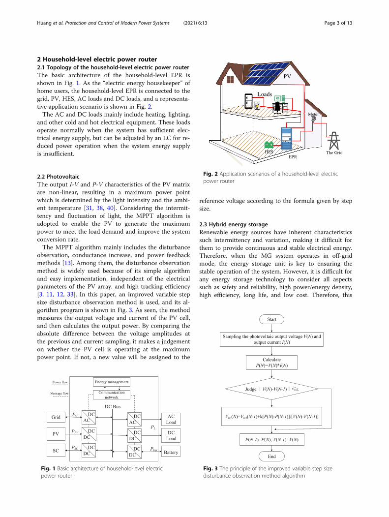
2 Household-level electric power router2.1 Topology of the household-level electric power routerThe basic architecture of the household-level EPR isshown in Fig. 1. As the “electric energy housekeeper” ofhome users, the household-level EPR is connected to thegrid, PV, HES, AC loads and DC loads, and a representa-tive application scenario is shown in Fig. 2.The AC and DC loads mainly include heating, lighting,
and other cold and hot electrical equipment. These loadsoperate normally when the system has sufficient elec-trical energy supply, but can be adjusted by an LC for re-duced power operation when the system energy supplyis insufficient.
2.2 PhotovoltaicThe output I-V and P-V characteristics of the PV matrixare non-linear, resulting in a maximum power pointwhich is determined by the light intensity and the ambi-ent temperature [31, 38, 40]. Considering the intermit-tency and fluctuation of light, the MPPT algorithm isadopted to enable the PV to generate the maximumpower to meet the load demand and improve the systemconversion rate.The MPPT algorithm mainly includes the disturbance
observation, conductance increase, and power feedbackmethods [13]. Among them, the disturbance observationmethod is widely used because of its simple algorithmand easy implementation, independent of the electricalparameters of the PV array, and high tracking efficiency[3, 11, 12, 33]. In this paper, an improved variable stepsize disturbance observation method is used, and its al-gorithm program is shown in Fig. 3. As seen, the methodmeasures the output voltage and current of the PV cell,and then calculates the output power. By comparing theabsolute difference between the voltage amplitudes atthe previous and current sampling, it makes a judgementon whether the PV cell is operating at the maximumpower point. If not, a new value will be assigned to the
reference voltage according to the formula given by stepsize.
2.3 Hybrid energy storageRenewable energy sources have inherent characteristicssuch intermittency and variation, making it difficult forthem to provide continuous and stable electrical energy.Therefore, when the MG system operates in off-gridmode, the energy storage unit is key to ensuring thestable operation of the system. However, it is difficult forany energy storage technology to consider all aspectssuch as safety and reliability, high power/energy density,high efficiency, long life, and low cost. Therefore, this
Fig. 1 Basic architecture of household-level electricpower router
Fig. 2 Application scenarios of a household-level electricpower router
Fig. 3 The principle of the improved variable step sizedisturbance observation method algorithm
Huang et al. Protection and Control of Modern Power Systems (2021) 6:13 Page 3 of 13
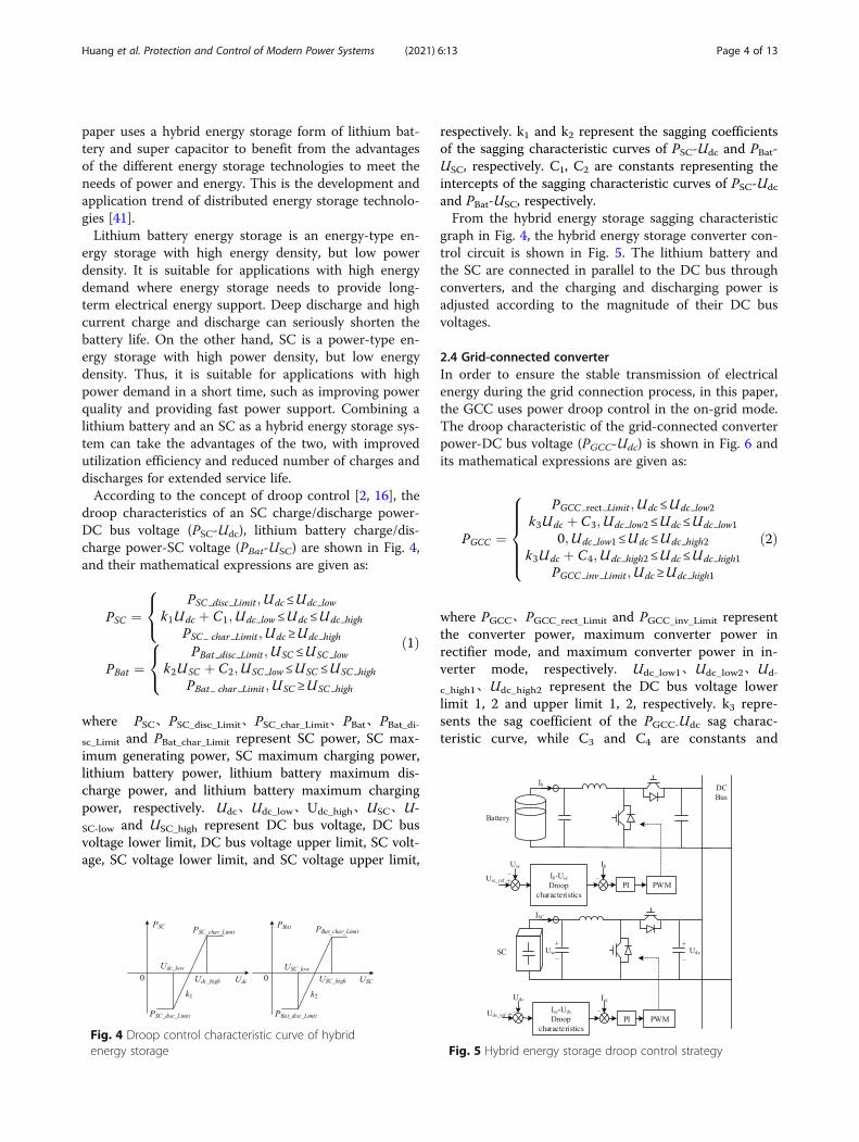
paper uses a hybrid energy storage form of lithium bat-tery and super capacitor to benefit from the advantagesof the different energy storage technologies to meet theneeds of power and energy. This is the development andapplication trend of distributed energy storage technolo-gies [41].Lithium battery energy storage is an energy-type en-
ergy storage with high energy density, but low powerdensity. It is suitable for applications with high energydemand where energy storage needs to provide long-term electrical energy support. Deep discharge and highcurrent charge and discharge can seriously shorten thebattery life. On the other hand, SC is a power-type en-ergy storage with high power density, but low energydensity. Thus, it is suitable for applications with highpower demand in a short time, such as improving powerquality and providing fast power support. Combining alithium battery and an SC as a hybrid energy storage sys-tem can take the advantages of the two, with improvedutilization efficiency and reduced number of charges anddischarges for extended service life.According to the concept of droop control [2, 16], the
droop characteristics of an SC charge/discharge power-DC bus voltage (PSC-Udc), lithium battery charge/dis-charge power-SC voltage (PBat-USC) are shown in Fig. 4,and their mathematical expressions are given as:
PSC ¼PSC disc Limit ;Udc≤Udc low
k1Udc þ C1;Udc low≤Udc≤Udc high
PSC char Limit ;Udc≥Udc high
8<
:
PBat ¼PBat disc Limit ;USC ≤USC low
k2USC þ C2;USC low≤USC ≤USC high
PBat char Limit ;USC ≥USC high
8<
:
ð1Þ
where PSC、PSC_disc_Limit、PSC_char_Limit、PBat、PBat_di-sc_Limit and PBat_char_Limit represent SC power, SC max-imum generating power, SC maximum charging power,lithium battery power, lithium battery maximum dis-charge power, and lithium battery maximum chargingpower, respectively. Udc、Udc_low、Udc_high、USC、U-SC-low and USC_high represent DC bus voltage, DC busvoltage lower limit, DC bus voltage upper limit, SC volt-age, SC voltage lower limit, and SC voltage upper limit,
respectively. k1 and k2 represent the sagging coefficientsof the sagging characteristic curves of PSC-Udc and PBat-USC, respectively. C1, C2 are constants representing theintercepts of the sagging characteristic curves of PSC-Udc
and PBat-USC, respectively.From the hybrid energy storage sagging characteristic
graph in Fig. 4, the hybrid energy storage converter con-trol circuit is shown in Fig. 5. The lithium battery andthe SC are connected in parallel to the DC bus throughconverters, and the charging and discharging power isadjusted according to the magnitude of their DC busvoltages.
2.4 Grid-connected converterIn order to ensure the stable transmission of electricalenergy during the grid connection process, in this paper,the GCC uses power droop control in the on-grid mode.The droop characteristic of the grid-connected converterpower-DC bus voltage (PGCC-Udc) is shown in Fig. 6 andits mathematical expressions are given as:
PGCC ¼
PGCC rect Limit ;Udc≤Udc low2
k3Udc þ C3;Udc low2≤Udc≤Udc low1
0;Udc low1≤Udc≤Udc high2
k3Udc þ C4;Udc high2≤Udc≤Udc high1
PGCC inv Limit ;Udc≥Udc high1
8>>>><
>>>>:
ð2Þ
where PGCC、PGCC_rect_Limit and PGCC_inv_Limit representthe converter power, maximum converter power inrectifier mode, and maximum converter power in in-verter mode, respectively. Udc_low1、Udc_low2、Ud-
c_high1、Udc_high2 represent the DC bus voltage lowerlimit 1, 2 and upper limit 1, 2, respectively. k3 repre-sents the sag coefficient of the PGCC-Udc sag charac-teristic curve, while C3 and C4 are constants and
Fig. 4 Droop control characteristic curve of hybridenergy storage Fig. 5 Hybrid energy storage droop control strategy
Huang et al. Protection and Control of Modern Power Systems (2021) 6:13 Page 4 of 13
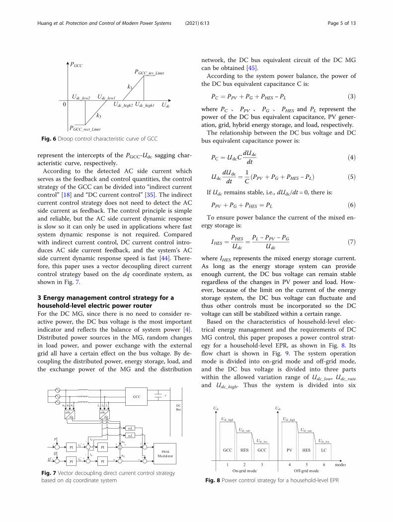
represent the intercepts of the PGCC-Udc sagging char-acteristic curve, respectively.According to the detected AC side current which
serves as the feedback and control quantities, the controlstrategy of the GCC can be divided into “indirect currentcontrol” [18] and “DC current control” [35]. The indirectcurrent control strategy does not need to detect the ACside current as feedback. The control principle is simpleand reliable, but the AC side current dynamic responseis slow so it can only be used in applications where fastsystem dynamic response is not required. Comparedwith indirect current control, DC current control intro-duces AC side current feedback, and the system’s ACside current dynamic response speed is fast [44]. There-fore, this paper uses a vector decoupling direct currentcontrol strategy based on the dq coordinate system, asshown in Fig. 7.
3 Energy management control strategy for ahousehold-level electric power routerFor the DC MG, since there is no need to consider re-active power, the DC bus voltage is the most importantindicator and reflects the balance of system power [4].Distributed power sources in the MG, random changesin load power, and power exchange with the externalgrid all have a certain effect on the bus voltage. By de-coupling the distributed power, energy storage, load, andthe exchange power of the MG and the distribution
network, the DC bus equivalent circuit of the DC MGcan be obtained [45].According to the system power balance, the power of
the DC bus equivalent capacitance C is:
PC ¼ PPV þ PG þ PHES − PL ð3Þwhere PC 、 PPV 、 PG 、 PHES and PL represent thepower of the DC bus equivalent capacitance, PV gener-ation, grid, hybrid energy storage, and load, respectively.The relationship between the DC bus voltage and DC
bus equivalent capacitance power is:
PC ¼ UdcCdUdc
dtð4Þ
UdcdUdc
dt¼ 1
CPPV þ PG þ PHES − PLð Þ ð5Þ
If Udc remains stable, i.e., dUdc/dt = 0, there is:
PPV þ PG þ PHES ¼ PL ð6ÞTo ensure power balance the current of the mixed en-
ergy storage is:
IHES ¼ PHES
Udc¼ PL − PPV − PG
Udcð7Þ
where IHES represents the mixed energy storage current.As long as the energy storage system can provideenough current, the DC bus voltage can remain stableregardless of the changes in PV power and load. How-ever, because of the limit on the current of the energystorage system, the DC bus voltage can fluctuate andthus other controls must be incorporated so the DCvoltage can still be stabilized within a certain range.Based on the characteristics of household-level elec-
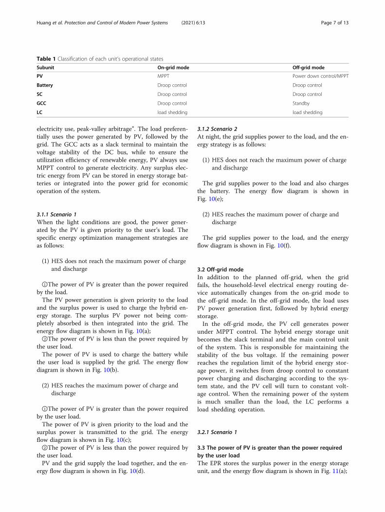
trical energy management and the requirements of DCMG control, this paper proposes a power control strat-egy for a household-level EPR, as shown in Fig. 8. Itsflow chart is shown in Fig. 9. The system operationmode is divided into on-grid mode and off-grid mode,and the DC bus voltage is divided into three partswithin the allowed variation range of Udc_low, Udc_rate
and Udc_high. Thus the system is divided into six
Fig. 6 Droop control characteristic curve of GCC
Fig. 7 Vector decoupling direct current control strategybased on dq coordinate system Fig. 8 Power control strategy for a household-level EPR
Huang et al. Protection and Control of Modern Power Systems (2021) 6:13 Page 5 of 13
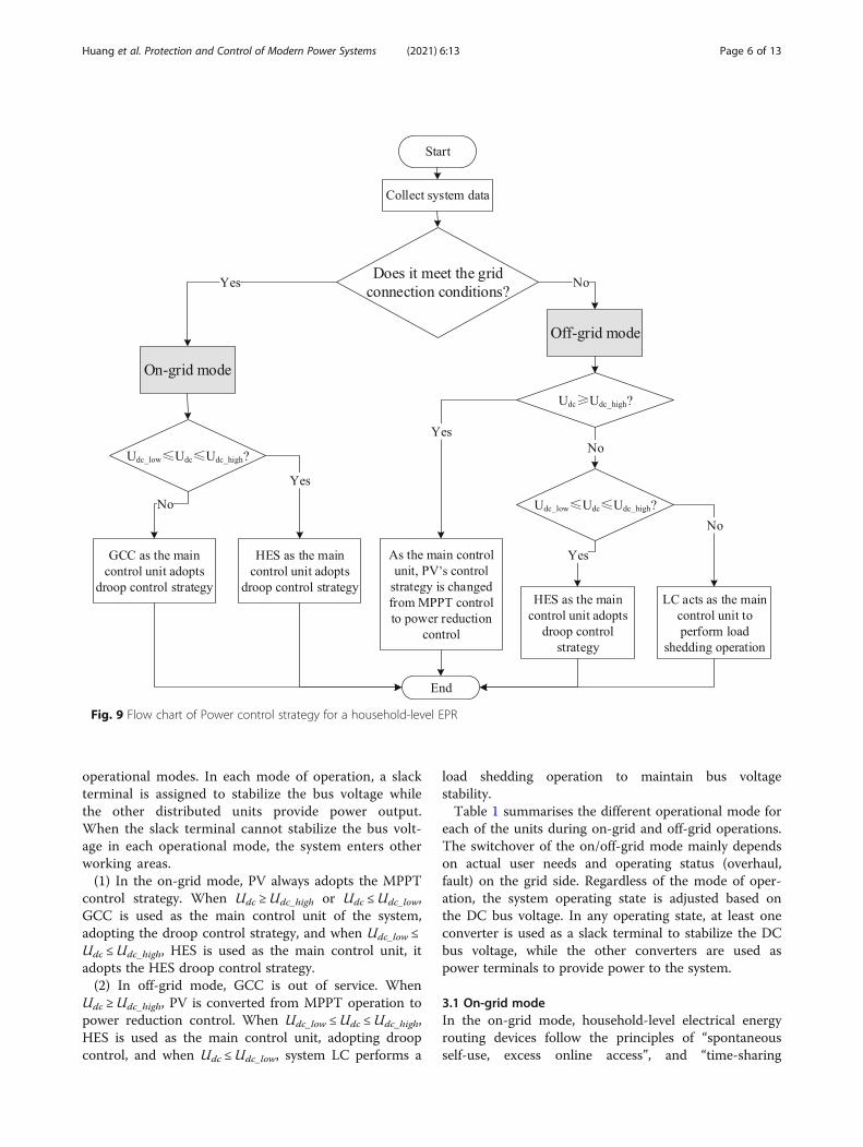
operational modes. In each mode of operation, a slackterminal is assigned to stabilize the bus voltage whilethe other distributed units provide power output.When the slack terminal cannot stabilize the bus volt-age in each operational mode, the system enters otherworking areas.(1) In the on-grid mode, PV always adopts the MPPT
control strategy. When Udc ≥Udc_high or Udc ≤Udc_low,GCC is used as the main control unit of the system,adopting the droop control strategy, and when Udc_low ≤Udc ≤Udc_high, HES is used as the main control unit, itadopts the HES droop control strategy.(2) In off-grid mode, GCC is out of service. When
Udc ≥Udc_high, PV is converted from MPPT operation topower reduction control. When Udc_low ≤Udc ≤Udc_high,HES is used as the main control unit, adopting droopcontrol, and when Udc ≤Udc_low, system LC performs a
load shedding operation to maintain bus voltagestability.Table 1 summarises the different operational mode for
each of the units during on-grid and off-grid operations.The switchover of the on/off-grid mode mainly dependson actual user needs and operating status (overhaul,fault) on the grid side. Regardless of the mode of oper-ation, the system operating state is adjusted based onthe DC bus voltage. In any operating state, at least oneconverter is used as a slack terminal to stabilize the DCbus voltage, while the other converters are used aspower terminals to provide power to the system.
3.1 On-grid modeIn the on-grid mode, household-level electrical energyrouting devices follow the principles of “spontaneousself-use, excess online access”, and “time-sharing
Fig. 9 Flow chart of Power control strategy for a household-level EPR
Huang et al. Protection and Control of Modern Power Systems (2021) 6:13 Page 6 of 13
electricity use, peak-valley arbitrage”. The load preferen-tially uses the power generated by PV, followed by thegrid. The GCC acts as a slack terminal to maintain thevoltage stability of the DC bus, while to ensure theutilization efficiency of renewable energy, PV always useMPPT control to generate electricity. Any surplus elec-tric energy from PV can be stored in energy storage bat-teries or integrated into the power grid for economicoperation of the system.
3.1.1 Scenario 1When the light conditions are good, the power gener-ated by the PV is given priority to the user’s load. Thespecific energy optimization management strategies areas follows:
(1) HES does not reach the maximum power of chargeand discharge
①The power of PV is greater than the power requiredby the load.The PV power generation is given priority to the load
and the surplus power is used to charge the hybrid en-ergy storage. The surplus PV power not being com-pletely absorbed is then integrated into the grid. Theenergy flow diagram is shown in Fig. 10(a);②The power of PV is less than the power required by
the user load.The power of PV is used to charge the battery while
the user load is supplied by the grid. The energy flowdiagram is shown in Fig. 10(b).
(2) HES reaches the maximum power of charge anddischarge
①The power of PV is greater than the power requiredby the user load.The power of PV is given priority to the load and the
surplus power is transmitted to the grid. The energyflow diagram is shown in Fig. 10(c);②The power of PV is less than the power required by
the user load.PV and the grid supply the load together, and the en-
ergy flow diagram is shown in Fig. 10(d).
3.1.2 Scenario 2At night, the grid supplies power to the load, and the en-ergy strategy is as follows:
(1) HES does not reach the maximum power of chargeand discharge
The grid supplies power to the load and also chargesthe battery. The energy flow diagram is shown inFig. 10(e);
(2) HES reaches the maximum power of charge anddischarge
The grid supplies power to the load, and the energyflow diagram is shown in Fig. 10(f).
3.2 Off-grid modeIn addition to the planned off-grid, when the gridfails, the household-level electrical energy routing de-vice automatically changes from the on-grid mode tothe off-grid mode. In the off-grid mode, the load usesPV power generation first, followed by hybrid energystorage.In the off-grid mode, the PV cell generates power
under MPPT control. The hybrid energy storage unitbecomes the slack terminal and the main control unitof the system. This is responsible for maintaining thestability of the bus voltage. If the remaining powerreaches the regulation limit of the hybrid energy stor-age power, it switches from droop control to constantpower charging and discharging according to the sys-tem state, and the PV cell will turn to constant volt-age control. When the remaining power of the systemis much smaller than the load, the LC performs aload shedding operation.
3.2.1 Scenario 1
3.3 The power of PV is greater than the power requiredby the user loadThe EPR stores the surplus power in the energy storageunit, and the energy flow diagram is shown in Fig. 11(a);
Table 1 Classification of each unit’s operational states
Subunit On-grid mode Off-grid mode
PV MPPT Power down control/MPPT
Battery Droop control Droop control
SC Droop control Droop control
GCC Droop control Standby
LC load shedding load shedding
Huang et al. Protection and Control of Modern Power Systems (2021) 6:13 Page 7 of 13
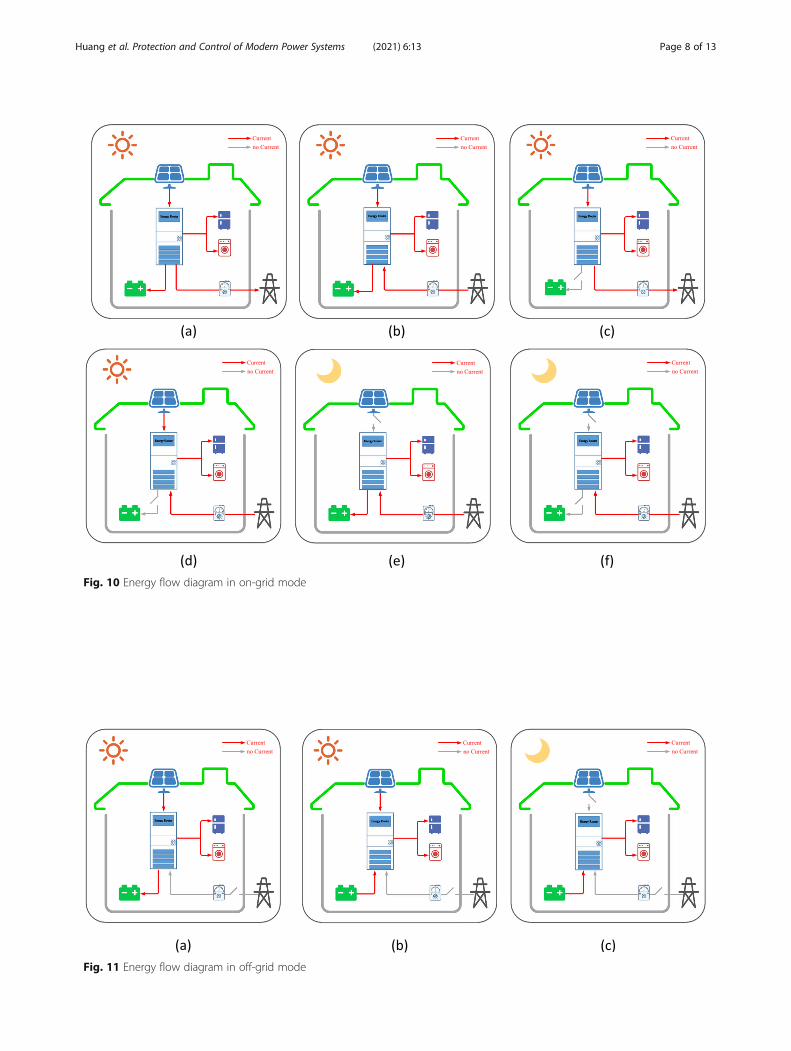
Fig. 10 Energy flow diagram in on-grid mode
Fig. 11 Energy flow diagram in off-grid mode
Huang et al. Protection and Control of Modern Power Systems (2021) 6:13 Page 8 of 13
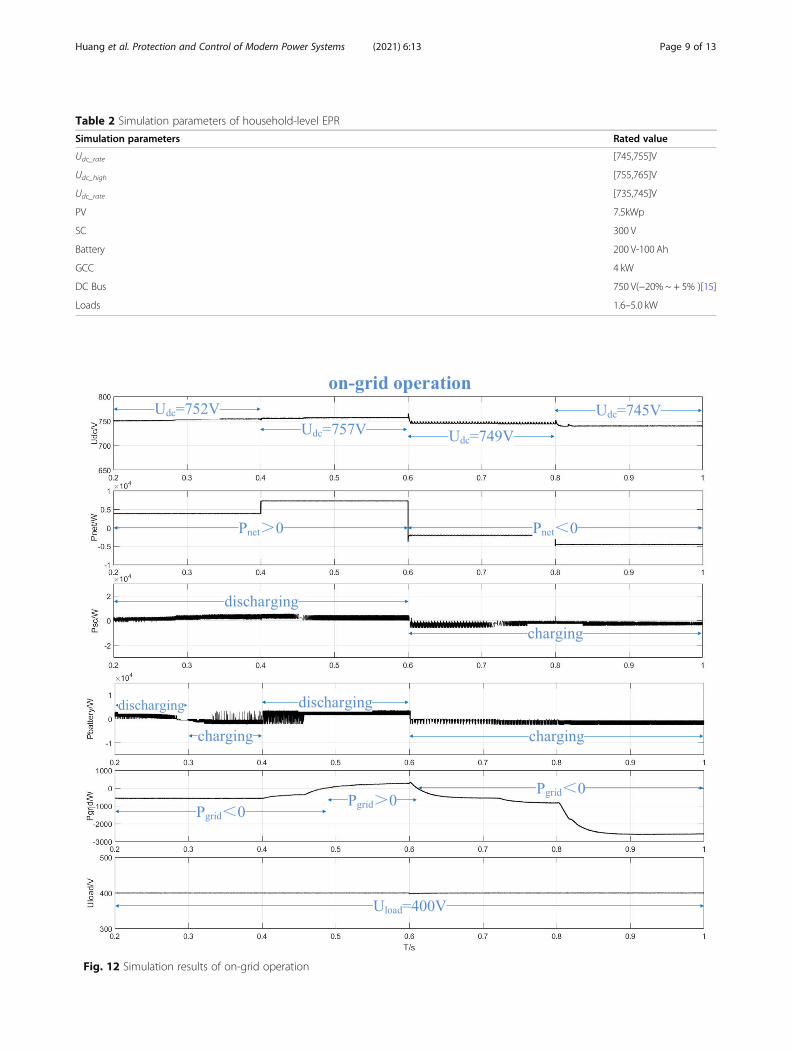
Table 2 Simulation parameters of household-level EPR
Simulation parameters Rated value
Udc_rate [745,755]V
Udc_high [755,765]V
Udc_rate [735,745]V
PV 7.5kWp
SC 300 V
Battery 200 V-100 Ah
GCC 4 kW
DC Bus 750 V(−20% ~ + 5% )[15]
Loads 1.6–5.0 kW
Fig. 12 Simulation results of on-grid operation
Huang et al. Protection and Control of Modern Power Systems (2021) 6:13 Page 9 of 13
3.4 The power of PV is less than the power required bythe user loadThe HES and PV supply the load together. The energyflow diagram is shown in Fig. 11(b).
3.4.1 Scenario 2At night or in cloudy conditions, the PV has no outputand the HES supplies power to the load. The energy flowdiagram is shown in Fig. 11(c).
4 Results and discussionsTo verify the power control strategy of the household-level EPR based on the HES droop control proposed inthis paper, a household-based EPR model is built inPSCAD/EMTDC according to the topology shown in
Fig. 1. A preferred 750 V in the low-voltage power sup-ply system is selected as the rated voltage of the MG DCbus [36]. The system simulation parameters are shownin Table 2. In Figs. 12, 13, 14, the net power Pnet equalsPpv minus Pload.
4.1 On-grid operational statusThe simulation results of on-grid operation are shown inFig. 12, in which the PV always operates in MPPT mode.As seen, during 0.2 ~ 0.6 s, the net power of the systemis positive, so the DC bus voltage rises slightly. Specific-ally, during 0.2 ~ 0.4 s, the DC bus voltage is maintainedat 752 V, the HES is used as a slack terminal, and thedroop control method is used to charge and discharge tomaintain the stability of the bus voltage. During 0.4 ~
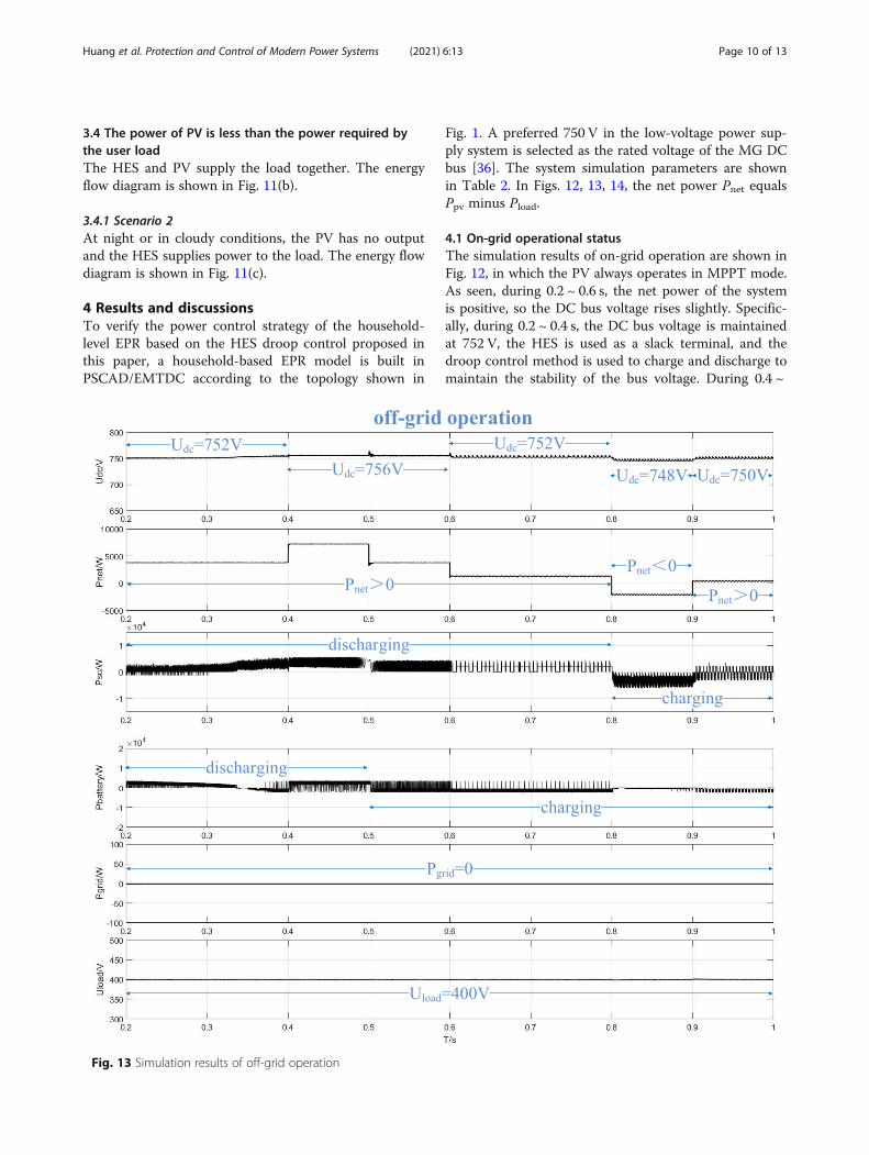
Fig. 13 Simulation results of off-grid operation
Huang et al. Protection and Control of Modern Power Systems (2021) 6:13 Page 10 of 13
0.6 s, the DC bus voltage is maintained at 757 V, whilethe GCC acts as the main control unit whose powertransmission to the grid is controlled to maintain thestability of the DC bus voltage. During 0.6 ~ 1.0 s, thenet power of the system is negative and the DC bus volt-age drops slightly. During 0.6 ~ 0.8 s, the DC bus voltageis maintained at 749 V whereas during 0.8 ~ 1.0 s, itdrops to 745 V. The HES and GCC serve as the slackterminal in the two stages, respectively.
4.2 Off-grid operational statusIn off-grid mode, the GCC is not enabled and simulationresults are shown in Fig. 13. As seen, during 0.2 ~ 0.4 s,the DC bus voltage is maintained at 752 V, the HES isused as a slack terminal, and the droop control method
is used to charge and discharge to maintain bus voltagestability. During 0.4 ~ 0.6 s, the DC bus voltage is main-tained at 756 V, while the PV becomes the main controlunit of the system by adopting a reduced power withconstant voltage control to stabilize the DC bus voltage.During 0.6 ~ 0.8 s, the DC bus voltage is maintained at752 V. As Pnet is decreased, the PV is switched back toMPPT control and HES becomes the main control unit.During 0.8 ~ 1.0 s, the DC bus voltage continues to de-crease, and the load controller performs load sheddingto maintain the bus voltage.
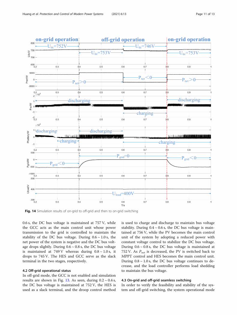
4.3 On-grid and off-grid seamless switchingIn order to verify the feasibility and stability of the sys-tem and off-grid switching, the system operational mode
Fig. 14 Simulation results of on-grid to off-grid and then to on-grid switching
Huang et al. Protection and Control of Modern Power Systems (2021) 6:13 Page 11 of 13

is simulated and verified, as shown in Fig. 14. As seen,during 0.2 ~ 0.4 s, the system operates in on-grid mode,and the DC bus voltage is maintained at 752 V. During0.4 ~ 0.8 s, the system operates in off-grid mode. So asseen, during 0.4 ~ 0.6 s, the DC bus voltage is maintainedat 753 V and during 0.6 ~ 0.8 s, Pnet is negative and theDC bus voltage drops to 746 V. During 0.8 ~ 1.0 s, thesystem goes back to on-grid operation, Pnet is positiveand the DC bus voltage rises to 753 V.
5 ConclusionsThe rapid development of PV and other intermittent re-newable energy power generation technologies requirespower control from the user side to ensure system sta-bility and supply security. Therefore, this paper proposesan energy power control strategy based on HES droopcontrol for the household-level EPR and a user’s actualoperating scenario. The proposed strategy is verifiedthrough simulations. The simulation results show that:
(1) In on-grid mode, under the support of the grid, thesystem can better maintain DC bus voltage stabilityand achieve stable operation under severe operatingconditions such as a rapid decrease of PV outputpower;
(2) In off-grid mode, the fluctuation of PV output has agreat impact on the system DC bus voltage.
(3) (3) The DC bus voltage fluctuations are smallduring on and off-grid switching, and seamlessswitching is achieved. The types of user-side loadsare increasingly diversified and intelligent. Thushow to classify and manage user-side loads will bethe focus of future research.
AbbreviationsMG: Microgrid; PV: Photovoltaic; SC: Supercapacitors; EPR: Electric powerrouter; LC: Load converter; HES: Hybrid energy storage; MPPT: MaximumPower Point Tracking; GCC: Grid-connected converter; I-V: Current-voltage; P-V: Power-voltage
AcknowledgmentsThis work is supported by National Key R&D Program of China(2018YFB0905000) and Science and Technology Project of State GridCorporation of China (SGTJDK00DWJS1800232).
Authors’ contributionsK. Huang and Y. Li, the main authors of this study, their contributionsincluded the model building, operation mode design and the paper writing.X. Zhang and L. Liu, they guided the study at all stage and improved thetext. Y. Zhu and X. Meng, the supervisors of the study, they reviewed andimproved the text. And Y. Zhu is the corresponding author. The authors readand approved the final manuscript.
FundingNational Key R&D Program of China (2018YFB0905000).Science and Technology Project of State Grid Corporation of China(SGTJDK00DWJS1800232).
Availability of data and materialsAll data generated or analyzed during this study are included in thepublished article (and its supplementary information files).
Declarations
Competing interestsThe authors declare that they have no competing interests.
Author details1NARI Technology Development Co., Ltd, No.19, Chengxin Avenue, JiangningDistrict, Nanjing City, Jiangsu Province, China. 2Nari Group Corporation/StateGrid Electric Power Research Institute, No.19, Chengxin Avenue, JiangningDistrict, Nanjing City, Jiangsu Province, China. 3School of Physics, Universityof Oxford, Oxford OX13RH, UK. 4Key Laboratory of Smart Grid of Ministry ofEducation, Tianjin University, Tianjin 300072, China.
Received: 17 July 2020 Accepted: 9 March 2021
References1. Bayati, M., Abedi, M., Gharehpetian, G. B., et al. (2019). Short-term interaction
between electric vehicles and microgrid in decentralized vehicle-to-gridcontrol methods [J]. Protection and Control of Modern Power Systems, 4(1),1–11.
2. Bo, W., Wenping, Q., Xiaoqing, H., et al. (2015). Control strategy of hybridenergy storage systems in DC microgrid based on voltage droop method[J]. Power System Technology, 39(4), 892–898.
3. Chao, Z., & Xiangning, H. (2006). Short-current combined with perturbationand observation maximum-power-point tracking method for photovoltaicpower systems [J]. Proceedings of the CSEE, 026(020), 98–102.
4. Chen, D., & Xu, L. (2012). Autonomous DC voltage control of a DC microgridwith multiple slack terminals [J]. Power Systems IEEE Transactions on, 27(4),1897–1905. https://doi.org/10.1109/TPWRS.2012.2189441.
5. Chen, H., Wang, X., Li, Z., et al. (2019). Distributed sensing and cooperativeestimation/detection of ubiquitous power internet of things [J]. Protectionand Control of Modern Power Systems, 4(1), 1–8.
6. Cheng, Y., & Zhang, C. (2017). Configuration and operation combinedoptimization for EV battery swapping station considering PV consumptionbundling [J]. Protection and Control of Modern Power Systems, 2(1), 26.https://doi.org/10.1186/s41601-017-0056-y.
7. China Electricity Council Standardization Management Center. ChinaElectricity Council Standardization Management Center on the solicitationof the national standard "Energy Internet Part 5: Energy Router (EnergyRouter) Functional Specifications and Technical Requirements" (Draft forComments) [N/OL], 2017-12-06. http://dls.cec.org.cn/yijianzhengqiu/2017-12-06/175753.html. Accessed 28 May 2020.
8. Chuang, L., & Yuemei, Z. (2017). Topological structure and control strategyof hybrid cascaded power electronic transformer [J]. Power SystemTechnology, 2, 596–603.
9. Chunming, T., Siping, L., Fan, X., & Zheng, L. (2018). Optimal control strategyof three-port DC energy router under TCM modulation [J]. Power SystemTechnology, 42(8), 2503–2511.
10. Daozuo, J., & Zheng, H. (2012). Current status and prospects of DCdistribution network research [J]. Automation of Electric Power Systems, 8,98–104.
11. Fei, W., Shijie, Y., Jianhui, S., et al. (2005). Research on photovoltaic grid-connected power system [J]. Transactions of China Electrotechnical Society,020(005), 72–74,91.
12. Femia, N., Petrone, G., Spagnuolo, G., & Vitelli, M. (2005). Optimization ofperturb and observe maximum power point tracking method [J]. IEEETransactions on Power Electronics, 20(4), 963–973. https://doi.org/10.1109/TPEL.2005.850975.
13. Feng, X. (2013). Research on modeling and control strategy of microgrid [D].Nanjing University of Science & Technology.
14. Gu, Y., Xiang, X., Li, W., & He, X. (2014). Mode-adaptive decentralized controlfor renewable DC microgrid with enhanced reliability and flexibility [J]. IEEETransactions on Power Electronics, 29(9), 5072–5080. https://doi.org/10.1109/TPEL.2013.2294204.
15. Guideline for standard voltages of medium and low voltage DC distributionsystem: GB/T 35727—2017[S]. 2017.
16. Jihong, Z., Peihong, Y., Fei, Z., et al. (2018). Multi mode droop controlstrategy for hybrid energy storage of micro-grid [J]. Electrical and energymanagement technology, 000(001), 78–83.
Huang et al. Protection and Control of Modern Power Systems (2021) 6:13 Page 12 of 13

17. Komurcugil, H., & Kukrer, O. (2006). A new control strategy for single-phase shunt active power filters using a Lyapunov function [J]. IEEETransactions on Industrial Electronics, 53(1), 305–312. https://doi.org/10.1109/TIE.2005.862218.
18. Kuihua, W., Yuling, L., Ping, L., et al. (2008). Current source PWM rectifierbased on indirect current control [J]. Proceedings of the CSU-EPSA, 03, 66–69.
19. Mao, C., Wang, D., & Shu, F. (2010). Electronic power transformer [M]. ChinaElectric Power Press.
20. Mao, X., Falconers, S., & Ayanna, R. (2010). Energy based control designfor a solid state transformer [C]. In Proceedings of IEEE PES generalmeeting, (pp. 1–7).
21. Na, Z., Hui, Z., & Xiaowen, X. (2012). DC microgrid coordinated controlstrategy research [J]. Journal of Xi’an University of Technology, 04, 47–52.
22. Qianchen, G., Gang, Y., & Lidan, Z. (2019). Research status and prospects ofelectric energy router technology [J]. Electric Power Construction, 040(006),105–113.
23. Renle, H., Tianjiao, P., Kewen, L., et al. (2015). Design of functional systemand application scheme of urban energy internet [J]. Automation of ElectricPower Systems, 39(9), 26–33.
24. Runruo, C., Wu, H., & Yan, X. (2012). A three-port converter suitable for wideinput voltage range [J]. Proceedings of the Chinese Society for ElectricalEngineering, 32(27), 119–125.
25. Sun, K., Zhang, L., Xing, Y., et al. (2011). A distributed control strategy basedon DC bus signaling for modular photovoltaic generation systems withbattery energy storage [J]. IEEE Transactions on Power Electronics, 26(10),3032–3045. https://doi.org/10.1109/TPEL.2011.2127488.
26. Sundararajan, A., Khan, T., Moghadasi, A., et al. (2019). Survey onsynchrophasor data quality and cybersecurity challenges, and evaluation oftheir interdependencies. Journal of Modern Power Systems and Clean Energy,7(3), 449–467. https://doi.org/10.1007/s40565-018-0473-6.
27. Tao, Z., Fuxing, Z., & Yan, Z. (2016). Study on energy management system ofenergy internet [J]. Power System Technology, v.40(386(01)), 156–165.
28. Tarnow, A., Haines, L., Barrera, J., & Meyer, A. (2001). Design of a fuel cellhybrid electric heavy duty vehicle [C]. In Proceedings of the 18thinternational electric vehicle symposium (EVS.18).
29. Valderrama, G. E., Stankovic, A. M., & Mattavelli, P. (2001). Dissipativity-basedadaptive and robust control of UPS in unbalanced operation [J]. PowerElectronics IEEE Transactions on, 18(4), 1056–1062.
30. Wang, D., Tian, J., Mao, C., Lu, J., Duan, Y., Qiu, J., & Cai, H. (2016). A 10.kV/400.V 500.kVA electronic power transformer [J]. IEEE Transactions onIndustrial Electronics, 63(11), 6653–6663. https://doi.org/10.1109/TIE.2016.2586440.
31. Wang, T., Xu, J., Qingzhu, S., et al. (2020). Research on non-scheduledislanding supplied by photovoltaic power generations [J]. Power SystemProtection and Control, 48(5), 173–180.
32. Wanxing, S., Wu, M., Yu, J., et al. (2019). Key technologies and engineeringpractice of distributed renewable energy power generation clusterintegration and absorption [J]. Proceedings of the Chinese Society of ElectricalEngineering, 39(8), 2175–2186.
33. Wu, L., Zhengming, Z., Jianzheng, L., et al. (2006). Implementation of asingle-stage three-phase grid-connected photovoltaic system with reactivepower compensation [J]. Transactions of China Electrotechnical Society,021(001), 28–32.
34. Wuhua, I., Yunjie, G. U., Yuxiang, W., et al. (2015). Control architecture andhierarchy division for renewable energy DC microgrids [J]. Automation ofElectric Power Systems.
35. Xiaojun, Z. (2010). The research on three phase high power PWM rectifiersystem [D]. Harbin Engineering University.
36. Xisheng, T. (2020). Interpretation of GB/T 35727–2017 guideline for standardvoltages of medium and low voltage DC distribution system [J]. Automationof Electric Power Systems, 44(1), 23–28.
37. Yao, Z., & Xiao, L. (2013). Control of single. Phase grid. Connected inverterswith nonlinear loads [J]. IEEE Transactions on Industrial Electronics, 60(4),1384–1389.
38. Yongjun, Z., Siheng, Z., Siliang, L., & Yingqi, Y. (2020). Dual planning ofa distribution transformer considering the impact of distributedphotovoltaics and energy storage access [J]. Power System Protectionand Control, 48(24), 9–15.
39. Zhang, J., Wang, W., & Bhattacharya, S. (2012). Architecture of solid statetransformer. Based energy router and models of energy traffic [C]. InInnovative smart grid technologies. IEEE.
40. Zhang, L., Samson Shenglong, Y. U., Fernando, T., et al. (2019). An onlinemaximum power point capturing technique for high-efficiency powergeneration of solar photovoltaic systems [J]. Journal of Modern PowerSystems and Clean Energy, 7(2), 357–368.
41. Zhen, W. (2014). Research on key technologies of distributed energy storagesystem [D]. Tianjin University.
42. Zhenming, Z., Gaohui, F., Liqiang, Y., et al. (2017). The development and keyTechnologies of Electric Energy Router [J]. Proceedings of the CSEE, 037(013),3823–3834.
43. Zhenya, L. (2015). Global energy internet [M]. China Electric Power Press.44. Zhongjiu, Z. (2011). Research on control strategies and application of three-
phase voltage source PWM rectifier [D]. Dalian University of Technology.45. Zhongtian, Z. (2018). Research on bus voltage control technology for DC
microgrid [D]. Shandong University of Technology.46. Zihu, Z. (2013). Research on four-port converter and its control strategy [D].
Nanjing University of Aeronautics and Astronautics.
Huang et al. Protection and Control of Modern Power Systems (2021) 6:13 Page 13 of 13


![Collecting household level data on varietal diversification [manual] · 2018-03-28 · Collecting household level data on varietal diversification and adaptation strategies to climate](https://img.pdfslide.us/doc/110x75/5e7e497adfd8246d5e506dba/collecting-household-level-data-on-varietal-diversification-manual-2018-03-28.jpg)