Embed Size (px)
Citation preview
INTERNATIONAL JOURNAL ON SMART SENSING AND INTELLIGENT SYSTEMS VOL.8, NO.3, SEPTEMBER 2015
1768
RESEARCH ON POWER CHARACTERISTIC OF THE
ELECTRIC FORKLIFT EPS SYSTEM
Yan He and Benxian Xiao
School of Electrical Engineering and Automation
Hefei University of Technology, 230009
Hefei, China
Email: [email protected]
Submitted: Apr. 15, 2015 Accepted: July 10, 2015 Published: Sep. 1, 2015
Abstract - This paper has given the structure, operating principle, and force analysis of electric power
steering (EPS) system aimed at a type of forklift. Combing with forklift operating characteristic, three
variable power characteristics curve based on steering wheel torque, real-time speed, and load is
designed, so is the three dimensional diagram of forklift power gradient by using fuzzy rule. The
dynamic model of EPS system and two-degree-of-freedom linear model of forklift dynamics are
established. This paper presents a simulation on the basis of three variable power characteristics and
dynamic model. The results show that forklift EPS system can provide appropriate power according to
the changes of speed and load. It also can meet the demands of coordination between steering
portability and road sense.
Index terms: EPS system of forklift, power gradient, three variable power characteristics curve, modeling,
simulation.
Yan He and Benxian Xiao, RESEARCH ON POWER CHARACTERISTIC OF THE ELECTRIC FORKLIFT EPS SYSTEM
1769
I. INTRODUCTION
The application of forklift is changed from ports and wharfs in the past to every aspect of life
now, and is widely used to load and unload indoors and outdoors. Being a key part of forklift,
steering system performance determined its safety operating.
With the continuous renewal of automotive electronic technology, there are different degrees of
breakthrough in terms of EPS system research in every way, and the scope of EPS application
also expanded gradually. In recent years, achievements have been obtained in EPS and forklift
control system both in China and abroad[1-5].
Nowadays, forklift EPS research focus on building more precise EPS model, descripting power
characteristics curve, improving control strategy and fault diagnosis, and the reliability of
controller[6-12].
This paper content and innovation mainly includes: (1) give the basic structure and operating
principle of electric power steering (EPS) system aimed at a type of forklift. (2) analyze basic
requirements of the design of power characteristics curve. Considering load changes have a
greater influence on forklift steering, this paper introduces weight signal. Combining speed and
hand force of steering handwheel, the power gradient is deduced and target current is calculated
by using fuzzy inference, thus a more reasonable power characteristics curve is obtained. The
advantage of fuzzy inference is to improve the power characteristics by adjusting the membership
functions and the control rules. (3) MATLAB simulation of steering portability and road sense.
II. THE STRUCTURE AND OPERATING PRINCIPLE OF FORKLIFT EPS SYSTEM
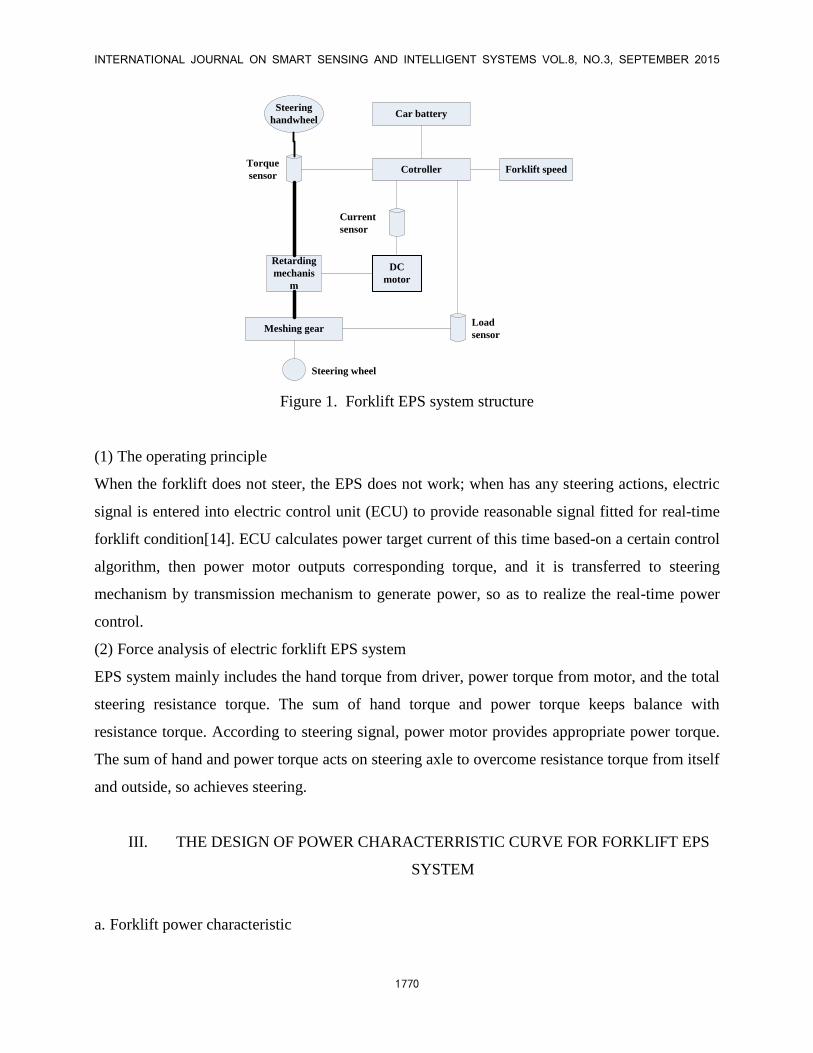
Taking a type of forklift as an example, EPS system of a steering axle-type is adopted in the
mechanical structure. Its system structure is as shown in figure 1. It mainly includes car battery
(DC48V), steering pile pillar assembly (including steering handwheel, steering axle of input and
output), power motor assembly (including motor, retarding mechanism, and electromagnetic
clutch), electronic control unit (including all kinds of sensor and controller) and so on[13].
INTERNATIONAL JOURNAL ON SMART SENSING AND INTELLIGENT SYSTEMS VOL.8, NO.3, SEPTEMBER 2015
1770
Steering
handwheel
Retarding
mechanis
m
Meshing gear
Cotroller
Car battery
Forklift speed
DC
motor
Torque
sensor
Current
sensor
Load
sensor
Steering wheel
Figure 1. Forklift EPS system structure
(1) The operating principle
When the forklift does not steer, the EPS does not work; when has any steering actions, electric
signal is entered into electric control unit (ECU) to provide reasonable signal fitted for real-time
forklift condition[14]. ECU calculates power target current of this time based-on a certain control
algorithm, then power motor outputs corresponding torque, and it is transferred to steering
mechanism by transmission mechanism to generate power, so as to realize the real-time power
control.
(2) Force analysis of electric forklift EPS system
EPS system mainly includes the hand torque from driver, power torque from motor, and the total
steering resistance torque. The sum of hand torque and power torque keeps balance with
resistance torque. According to steering signal, power motor provides appropriate power torque.
The sum of hand and power torque acts on steering axle to overcome resistance torque from itself
and outside, so achieves steering.
III. THE DESIGN OF POWER CHARACTERRISTIC CURVE FOR FORKLIFT EPS
SYSTEM
a. Forklift power characteristic
Yan He and Benxian Xiao, RESEARCH ON POWER CHARACTERISTIC OF THE ELECTRIC FORKLIFT EPS SYSTEM
1771
The determination of dynamical characteristics is one of the core issues of EPS system. It means
the relationship between the power (provided by expected system) and real-time steering
conditions. The main involved problem is the balance between steering portability and road sense.
Common dynamical characteristics curve is usually expressed as the relationship among motor
output torque and steering wheel input torque, speed and other variables. The design’s purpose is
to determine present control target and determines the power magnitude provided by power
motor, that is the control rule of EPS system[15].
Combining with forklift operating features, we can infer that ideal power characteristic curve
should have the following features:
(1) If hand input torque by the driver is in a small range, the power motor doesn’t work in order
to keep a certain degree of road sense. As the speed increases, the scope of no working becomes
bigger correspondingly.
(2) If steering in situ, power mechanism provides maximum power to help the driver reduce
energy consumption.
(3) If at lower speed, power mechanism provides appropriate power.
(4) The power characteristic cure reflects changes of forklift load.
(5) If speed is bigger than the pre-set limit value, the electromagnetic clutch is separated, so the
power steering system is switched to purely mechanical steering system[16].
b. The determination of forklift power characteristic curve
Electric forklift is different from other common passenger vehicles. Its bigger self-weight and
load changes influence on power characteristic. That is to say, keeping the same system
parameters and road surface conditions, there is a corresponding relationship between resistance
force and load weight. Therefore, steering wheel load signal—G is introduced in this paper.
Combining speed signal—V with hand-force torque—Td, steering assistance characteristic curve
of the forklift is determined.
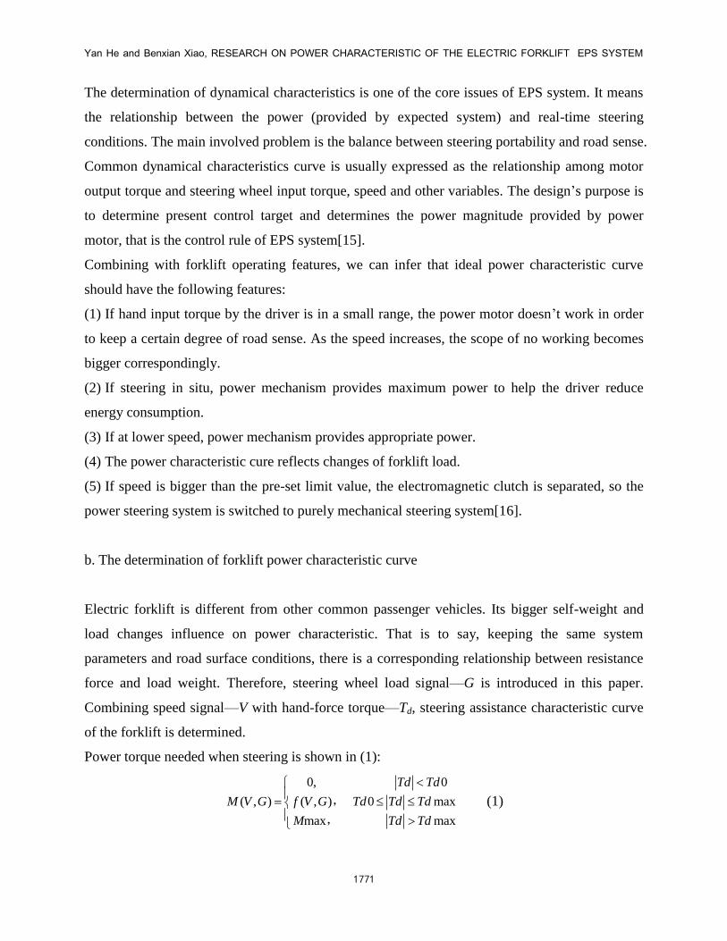
Power torque needed when steering is shown in (1):
0,
( , ) ( , )
max
M V G f V G
M
,
,
0
0 max
max
Td Td
Td Td Td
Td Td
(1)
INTERNATIONAL JOURNAL ON SMART SENSING AND INTELLIGENT SYSTEMS VOL.8, NO.3, SEPTEMBER 2015
1772
Because ( , , )df V G T is a function of three variables, it is difficult to fit and design. To simplify,
put this function into a product of a binary function and a unary function. It is shown in (2).
0
d 1 d0 0 max
max max
0,
( , , ) ( , )* ( )
d d
d d d d
d d
T T
M V G T K V G f T T T T T
M T T
,
,
(2)
In this equation, 1f is function about 0dTTd . Define k as power gradient, ( , )k K V G . It is
binary function of axle load and steering speed. It can get the value of power torque which should
be provided from power gradient at any time.
Normally, the table of steering power torque in specific axle load and speed can be list by
experimental values, so the corresponding power gradient can be calculated and the model of
power gradient can be fitted. In an actual situation, it is unrealistic and unnecessary to divide
input variable—speed. Firstly, drivers usually judge speed and load by their experience and habit.
The second, electric forklift EPS system is complex, nonlinear and uncertain. Because it is
influenced by road friction and outside disturbance, so it is difficult to establish a precise model
to present the relationship among motor power, speed, steering wheel torque, and load. These
factors suggest that it is a good choice to introduce fuzzy relation into the design of power
steering characteristic curve.
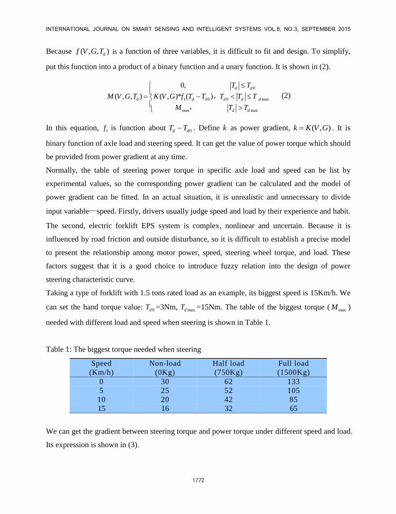
Taking a type of forklift with 1.5 tons rated load as an example, its biggest speed is 15Km/h. We
can set the hand torque value: 0dT =3Nm, maxdT =15Nm. The table of the biggest torque ( maxM )
needed with different load and speed when steering is shown in Table 1.
Table 1: The biggest torque needed when steering
Speed
(Km/h)
Non-load
(0Kg)
Half load
(750Kg)
Full load
(1500Kg)
0 30 62 133
5 25 52 105
10 20 42 85
15 16 32 65
We can get the gradient between steering torque and power torque under different speed and load.
Its expression is shown in (3).
Yan He and Benxian Xiao, RESEARCH ON POWER CHARACTERISTIC OF THE ELECTRIC FORKLIFT EPS SYSTEM
1773
max dmax
dmax d0-
M Tk
T T
(3)
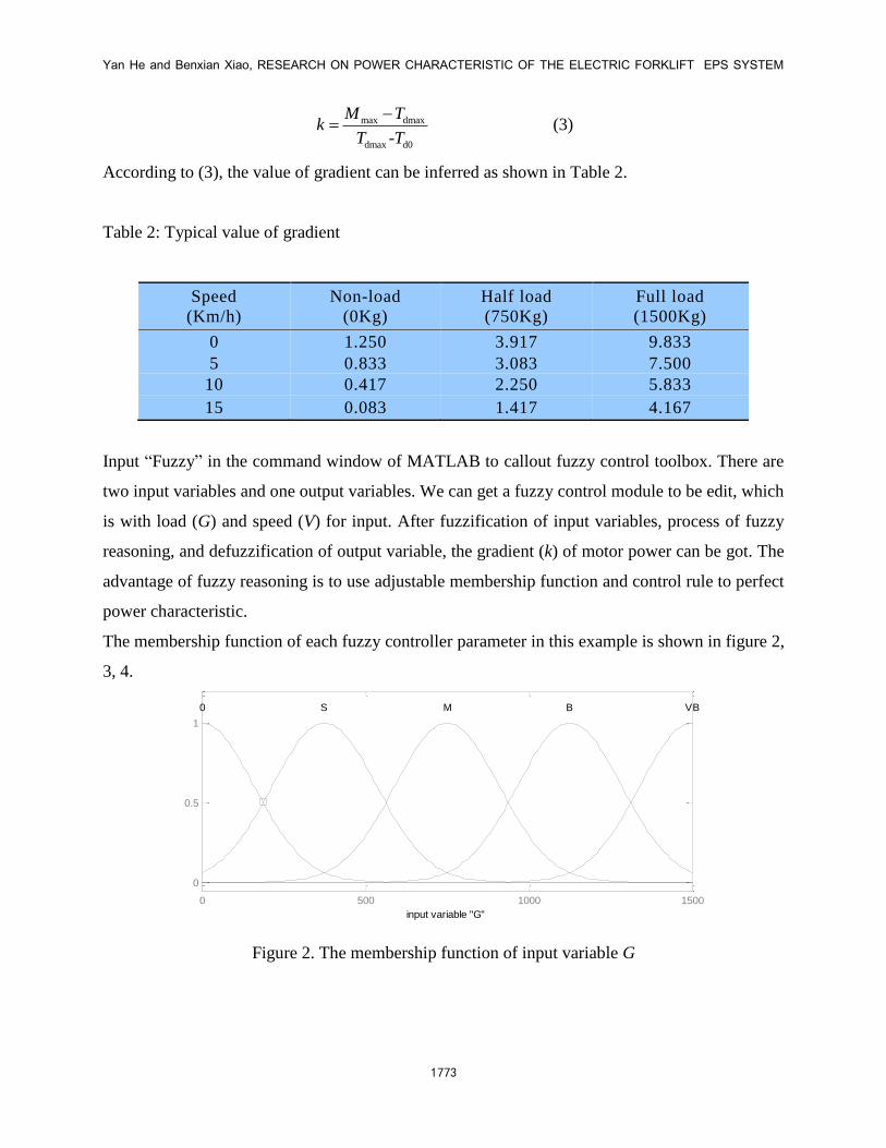
According to (3), the value of gradient can be inferred as shown in Table 2.
Table 2: Typical value of gradient
Speed
(Km/h)
Non-load
(0Kg)
Half load
(750Kg)
Full load
(1500Kg)
0 1.250 3.917 9.833
5 0.833 3.083 7.500
10 0.417 2.250 5.833
15 0.083 1.417 4.167
Input “Fuzzy” in the command window of MATLAB to callout fuzzy control toolbox. There are
two input variables and one output variables. We can get a fuzzy control module to be edit, which
is with load (G) and speed (V) for input. After fuzzification of input variables, process of fuzzy
reasoning, and defuzzification of output variable, the gradient (k) of motor power can be got. The
advantage of fuzzy reasoning is to use adjustable membership function and control rule to perfect
power characteristic.
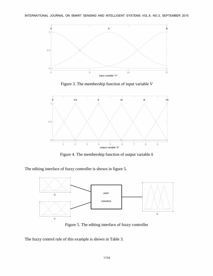
The membership function of each fuzzy controller parameter in this example is shown in figure 2,
3, 4. FIS Variables
G
V
k
0 500 1000 1500
0
0.5
1
Membership function plots
input variable "G"
0 S M B VB
Figure 2. The membership function of input variable G
INTERNATIONAL JOURNAL ON SMART SENSING AND INTELLIGENT SYSTEMS VOL.8, NO.3, SEPTEMBER 2015
1774
FIS Variables
G
V
k
0 5 10 15
0
0.5
1
Membership function plots
input variable "V"
0 S B
Figure 3. The membership function of input variable V
FIS Variables
G
V
k
1 2 3 4 5 6 7 8 9
0
0.5
1
Membership function plots
output variable "k"
0 VS S M B VB
Figure 4. The membership function of output variable k
The editing interface of fuzzy controller is shown in figure 5.
G
V
k
paper
(mamdani)
Figure 5. The editing interface of fuzzy controller
The fuzzy control rule of this example is shown in Table 3.
Yan He and Benxian Xiao, RESEARCH ON POWER CHARACTERISTIC OF THE ELECTRIC FORKLIFT EPS SYSTEM
1775
Table 3: The fuzzy control rule
0 S M B VB
0 VS S M B VB
S 0 VS S M B
B 0 0 VS S M
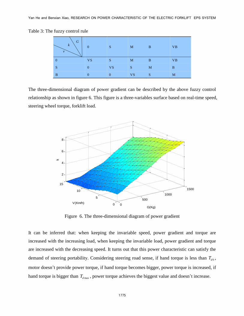
The three-dimensional diagram of power gradient can be described by the above fuzzy control
relationship as shown in figure 6. This figure is a three-variables surface based on real-time speed,
steering wheel torque, forklift load.
0
500
1000
1500
0
5
10
15
2
4
6
8
G(Kg)
V(Km/h)
k
Figure 6. The three-dimensional diagram of power gradient
It can be inferred that: when keeping the invariable speed, power gradient and torque are
increased with the increasing load, when keeping the invariable load, power gradient and torque
are increased with the decreasing speed. It turns out that this power characteristic can satisfy the
demand of steering portability. Considering steering road sense, if hand torque is less than 0dT ,
motor doesn’t provide power torque, if hand torque becomes bigger, power torque is increased, if
hand torque is bigger than maxdT , power torque achieves the biggest value and doesn’t increase.
G k
v
INTERNATIONAL JOURNAL ON SMART SENSING AND INTELLIGENT SYSTEMS VOL.8, NO.3, SEPTEMBER 2015
1776
IV. THE MODEL ESTABLISHMENT FOR FOERKLIST EPS SYSTEM
a. Dynamic model establishment for EPS system
Based on structure of forklift in figure 1, let it be supposed that: where Jk,Jc,Jm are moment of
inertia of steering wheel, steering mechanism, motor, and Bk,Bc,Bm are damping coefficient of
them respectively. Tk,Tf,Tm,Ta,Tn are steering wheel input torque, equivalent steering
resistance torque of output axle, motor electromagnetic torque, motor output torque, and output
torque of torque sensor. θk,θc,θm are steering wheel angle, which is equivalent to the output
axle from steering wheel, motor angle. g is transmission ratio of retarding mechanism (from
motor to output axle). Ks is stiffness of torque sensor.
a.i The establishment of power motor model
The equation of permanent magnet DC power motor is as following in (4)[17].
d dd db
I IU E RI L K RI Lt t
(4)
Where U is motor voltage, E is back EMF produced by motor, R is equivalent resistance in motor
loop, L is motor inductance, Kb is back EMF coefficient, is motor speed.
Equation (5) and (6) can be inferred by the analysis for the mechanical part of motor. Where aK
is coefficient of motor electromagnetic torque.
dtB
dtJ
g
TT m
m
mmm
2
a dd (5)
IKTm a (6)
a.ii The establishment of steering system model
Ignoring motor stiffness, the relationship between motor angle and output axle angle can be
expressed as equation (7).
cg m (7)
Yan He and Benxian Xiao, RESEARCH ON POWER CHARACTERISTIC OF THE ELECTRIC FORKLIFT EPS SYSTEM
1777
By modeling for steering wheel dynamics:
dtB
dtJTT k
kknk
k
2 dd (8)
By modeling for torque sensor dynamics:
)csn KT -( k (9)
By modeling for output axle dynamics:
dtB
dtJTTT c
ccf
c
2
an
dd (10)
If forklift’s tire is turning in a small angle, its lateral deviation characteristic appears to be a linear
relationship, Where Kc is equivalent output axle stiffness of lateral deviation.
ccKT f (11)
The relationship between practical power torque and motor output torque is shown in (12).
gTM m (12)
b. Dynamic model establishment for forklift
Considering that the two-degree-of-freedom linear model of forklift dynamics is in common use,
in this model, lateral acceleration is less than 0.4g. Suppose some secondary causes can be
ignored to highlight features of lateral movement in simplified figure. If the vehicle is driving at
constant speed, only movements on horizontal plane will be considered[13,18,19], the
characteristic of tires keeps constant, and vehicle’s load is ignored, two-degree-of-freedom linear
model of forklift dynamics can be established as shown in figure 7.
INTERNATIONAL JOURNAL ON SMART SENSING AND INTELLIGENT SYSTEMS VOL.8, NO.3, SEPTEMBER 2015
1778
2
1
2 1u
2u u
v
abX
Y
L Y1FY2F
m0
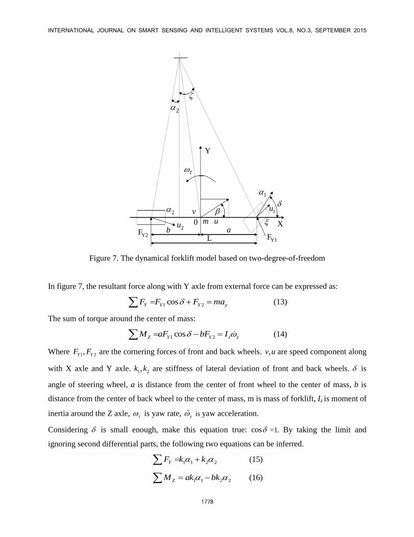
Figure 7. The dynamical forklift model based on two-degree-of-freedom
In figure 7, the resultant force along with Y axle from external force can be expressed as:
yYYY maFFF 21 cos (13)
The sum of torque around the center of mass:
zzYYZ IbFaFM 21 cos (14)
Where 1 2,Y YF F are the cornering forces of front and back wheels. ,v u are speed component along
with X axle and Y axle. 1 2,k k are stiffness of lateral deviation of front and back wheels. is
angle of steering wheel, a is distance from the center of front wheel to the center of mass, b is
distance from the center of back wheel to the center of mass, m is mass of forklift, Iz is moment of
inertia around the Z axle, r is yaw rate, z is yaw acceleration.
Considering is small enough, make this equation true: cos =1. By taking the limit and
ignoring second differential parts, the following two equations can be inferred.
2211 kkFY (15)
2211 bkkaM Z (16)
Yan He and Benxian Xiao, RESEARCH ON POWER CHARACTERISTIC OF THE ELECTRIC FORKLIFT EPS SYSTEM
1779
Supposing the speed of front axle and back axle are 1 2,u u , their side slip angle is 1 2, . The side
slip angle of the center of mass is , ( )v u . ξ is the included angle between u and X axle. Its
expression is as follows:
u
a
u
av rr
(17)
The side slip angle of front axle and back axle can be inferred by composition principle.
1 - - -ra
u
(18)
u
b
u
b rr
v2 (19)
Combing all equations, the expression of two-degree-of-freedom movement can be inferred as
follows:
zz
rr
Iakkbkau
bkak
uwvmbkaku
kk
12
2
1
2
21
12121
1
k1
(20)
V. THE SIMULATION OF POWER CHARACTERISTIC FOR FORKLIFT EPS SYSTEM
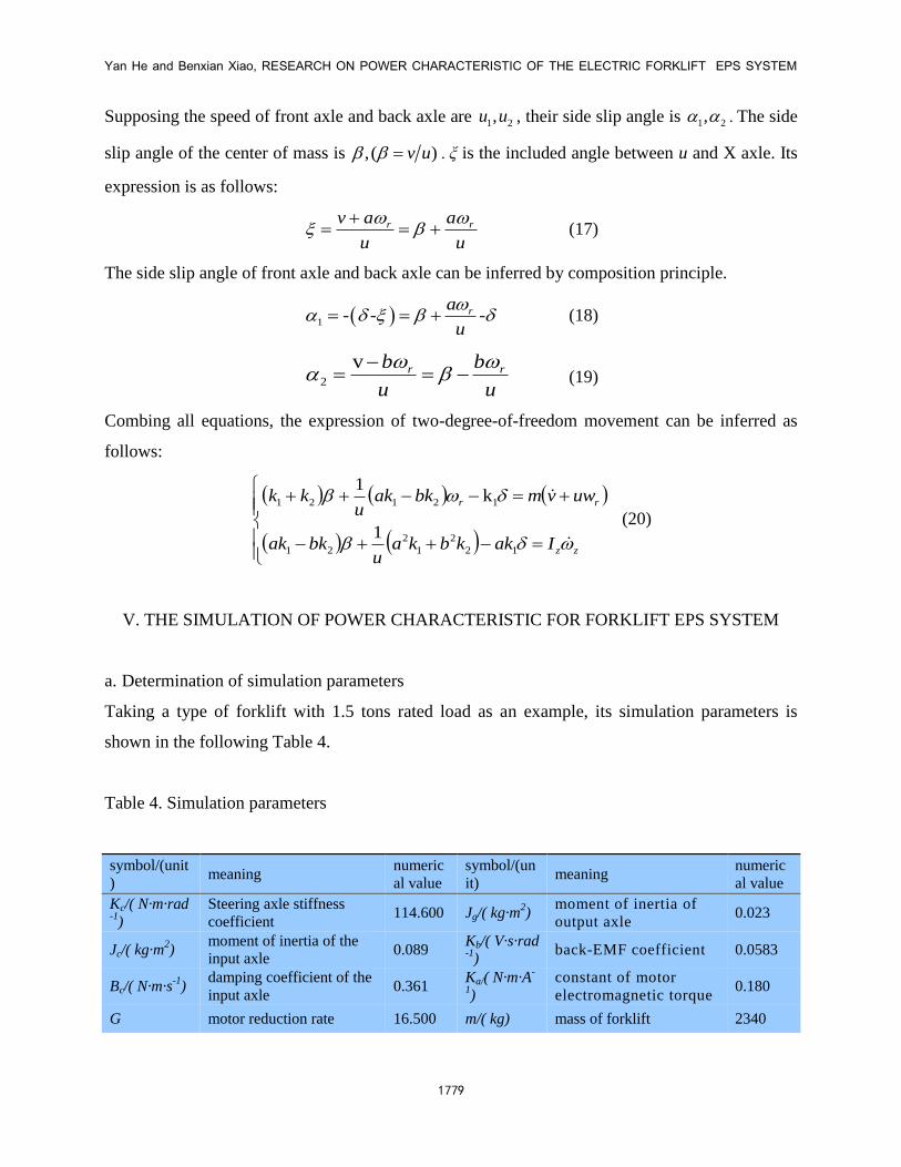
a. Determination of simulation parameters
Taking a type of forklift with 1.5 tons rated load as an example, its simulation parameters is
shown in the following Table 4.
Table 4. Simulation parameters
symbol/(unit
) meaning
numeric
al value
symbol/(un
it) meaning
numeric
al value
Kc/( N·m·rad-1
)
Steering axle stiffness
coefficient 114.600 Jg/( kg·m
2)
moment of inertia of
output axle 0.023
Jc/( kg·m2)
moment of inertia of the
input axle 0.089
Kb/( V·s·rad-1
) back-EMF coefficient 0.0583
Bc/( N·m·s-1
) damping coefficient of the
input axle 0.361
Ka/( N·m·A-
1)
constant of motor
electromagnetic torque 0.180
G motor reduction rate 16.500 m/( kg) mass of forklift 2340
INTERNATIONAL JOURNAL ON SMART SENSING AND INTELLIGENT SYSTEMS VOL.8, NO.3, SEPTEMBER 2015
1780
Bg/( N·m·s-1
) damping coefficient of the
output axle 0.023 a/(m)
distance from the center
of front wheel to the
center of mass
1.352
R/Ω resistance of motor
armature 0.450 b/(m)
distance from the center
of back wheel to the
center of mass
1.485
L/H inductance of motor
armature 2.339
k1/( N·rad-
1)
stiffness of lateral
deviation of front wheels -62618
Jm/( kg·m2) moment of inertia of motor
2.250/104
k2/( N·rad-
1)
stiffness of lateral
deviation of back wheels -110245
Bm/( N·m·s-1
) damping coefficient of
motor 0.029 Iz/( kg·m
2)
moment of inertia around
the center of mass 3895
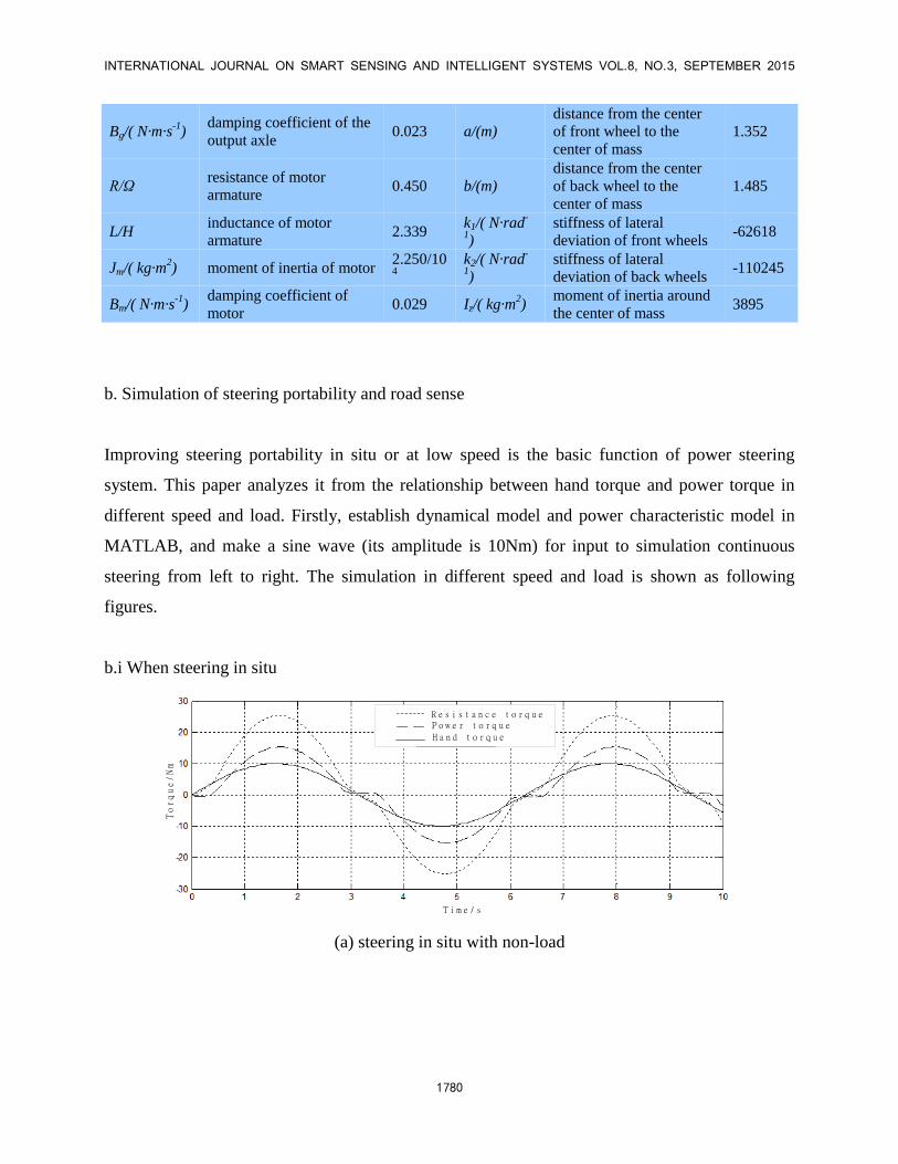
b. Simulation of steering portability and road sense
Improving steering portability in situ or at low speed is the basic function of power steering
system. This paper analyzes it from the relationship between hand torque and power torque in
different speed and load. Firstly, establish dynamical model and power characteristic model in
MATLAB, and make a sine wave (its amplitude is 10Nm) for input to simulation continuous
steering from left to right. The simulation in different speed and load is shown as following
figures.
b.i When steering in situ
R e s i s t a n c e t o r q u eP o w e r t o r q u e
H a n d t o r q u e
T i m e / s
Torque/Nm
(a) steering in situ with non-load
Yan He and Benxian Xiao, RESEARCH ON POWER CHARACTERISTIC OF THE ELECTRIC FORKLIFT EPS SYSTEM
1781
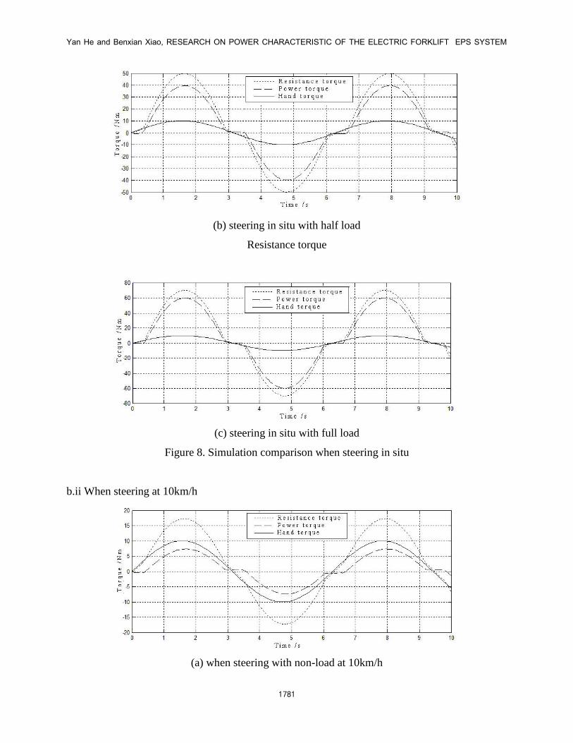
(b) steering in situ with half load
Resistance torque
(c) steering in situ with full load
Figure 8. Simulation comparison when steering in situ
b.ii When steering at 10km/h
(a) when steering with non-load at 10km/h
INTERNATIONAL JOURNAL ON SMART SENSING AND INTELLIGENT SYSTEMS VOL.8, NO.3, SEPTEMBER 2015
1782
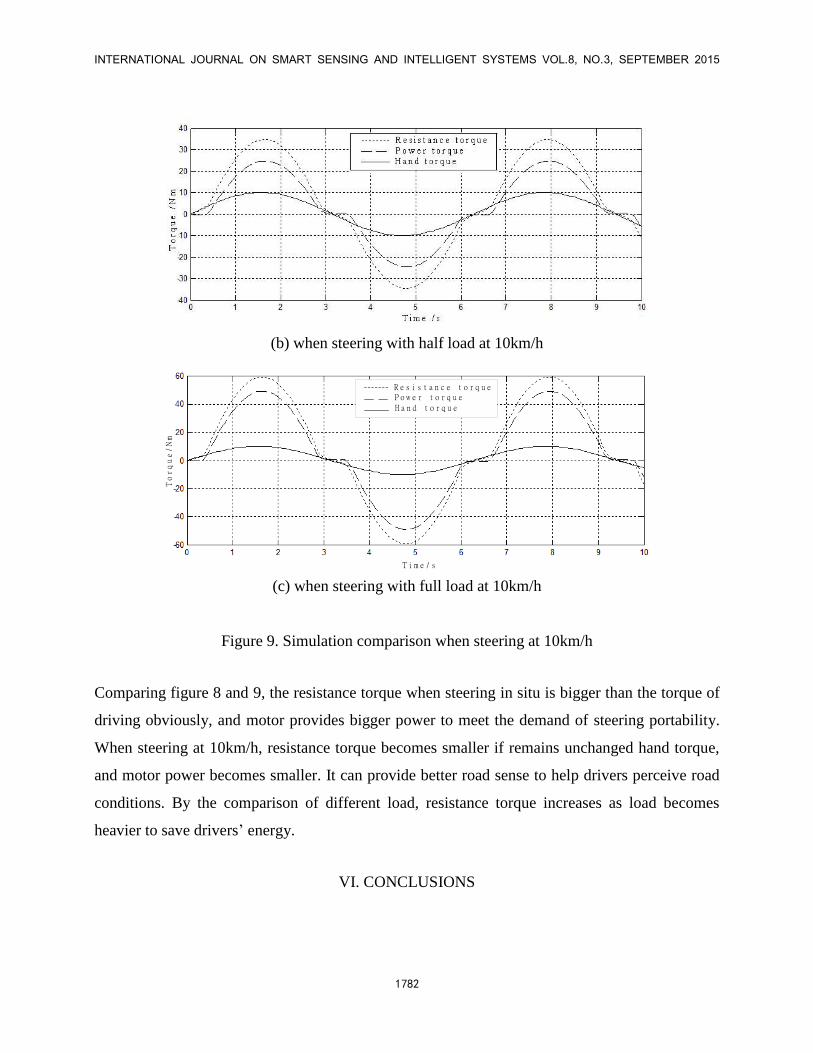
(b) when steering with half load at 10km/h
R e s i s t a n c e t o r q u eP o w e r t o r q u e
H a n d t o r q u e
T i m e / s
Torque/Nm
(c) when steering with full load at 10km/h
Figure 9. Simulation comparison when steering at 10km/h
Comparing figure 8 and 9, the resistance torque when steering in situ is bigger than the torque of
driving obviously, and motor provides bigger power to meet the demand of steering portability.
When steering at 10km/h, resistance torque becomes smaller if remains unchanged hand torque,
and motor power becomes smaller. It can provide better road sense to help drivers perceive road
conditions. By the comparison of different load, resistance torque increases as load becomes
heavier to save drivers’ energy.
VI. CONCLUSIONS
Yan He and Benxian Xiao, RESEARCH ON POWER CHARACTERISTIC OF THE ELECTRIC FORKLIFT EPS SYSTEM
1783
As the development of EPS system becomes more mature, it is widely used in forklift and gets
more and more attention. This paper takes a type of forklift as an example, and presents the
structure, operating principle and force analysis of EPS system. Three variable power
characteristics curve based on steering wheel torque, real-time speed, and load is established by
using fuzzy control rule. The innovation of this paper is that load changes are being reflected on
the target current calculation of power motor.
The dynamic model of EPS system is established. The simulation results show that three variable
power characteristics curve can meet the demands of coordination between steering portability
and road sense.
ACKNOWLEDGEMENTS
This work is supported by Hefei Banyitong Science and Technology Development Co. Ltd., the
authors are grateful to senior engineer Junliang Guo, Zijian Fang, Pengfei Li, Xingzhi Fang, Lei
Zhang, Zhu Li for their cooperation and helpful suggestions. Besides, my sincere thanks should
go to graduate students Jianan Wu, Luxi Pan, Jingjing Ma, Qinglin Zhang et al.
REFERENCES
[1] Baharom Masri B., Hussain Khalid, Day Andrew J, “Design of full electric power steering
with enhanced performance over that of hydraulic power-assisted steering”, Proceedings of the
Institution of Mechanical Engineers, Part D: Journal of Automobile Engineering, Vol 227, No. 3,
pp. 390-399, 2013.
[2] Rinchi Mirko, Pugi Luca, Bartolini Fabio, etc. “Design of control system to prevent forklift
capsize”, International Journal of Vehicle Systems Modeling and Testing, Vol. 5, No. 1, pp. 35-
58, 2010.
[3] Park S.M., Park T.W., Lee S.H., etc. “Analytical study to estimate the performance of the
Power Shift Drive (PSD) Axle for a forklift”, International Journal of Automotive Technology,
Vol. 11, No. 1, pp. 49-56, 2010.
[4] Ma DongMei, “Design of electric power steering for forklift based on ARM”, Applied
Mechanics and Materials, Vol.347-350, pp. 548-552, 2013.
INTERNATIONAL JOURNAL ON SMART SENSING AND INTELLIGENT SYSTEMS VOL.8, NO.3, SEPTEMBER 2015
1784
[5] Cui Shengmin, Xu Bo, Pan Wenfeng, etc. “The matching design and performance simulation
of transmission system parameters of an electric forklift”, Applied Mechanics and Materials,
Vol.278-280, pp. 328-331, 2013.
[6] Chen Xiang, Yang Tiebao, Chen Xiaoqun, etc. “A generic model-based advanced control of
electric power-assisted steering systems”, IEEE Transactions on Control Systems Technology,
Vol. 16, No. 6, pp. 1289-1300, 2008.
[7] Qun, Zeng, “The design of power assisted characteristic curve for electric power steering
system”, Journal of Convergence Information Technology, Vol. 7, No. 17, 2012, pp. 260-266.
[8] Geng GuoQing, “Design and stabilization analysis of the parabola-type assistance
characteristic of electric power steering system”, Advanced Materials Research, Vol. 779, pp.
556-559, 2013.
[9] Han JiongGang, Shen RongWei, Tai XiaoHong, etc. “Research on assist characteristic of
electric power steering system based on adaptive neuro-fuzzy control”, Applied Mechanics and
Materials, Vol.347-350, pp. 357-361, 2013.
[10] Dannöhl C., Müller S., “Ulbrich H. H∞-control of a rack-assisted electric power steering
system”, Vehicle System Dynamics, Vol. 50, No. 4, pp. 527-544, 2012.
[11] Marouf Alaa, Djemai Mohamed, Sentouh Chouki, etc. “A new control strategy of an
electric-power-assisted steering system”, IEEE Transactions on Vehicular Technology, Vol. 61,
No. 8, pp. 3574-3589, 2012.
[12] Chitu Cristian, Lackner Jochen, Horn Martin, etc. “Controller design for an electric power
steering system based on LQR techniques”, The International Journal for Computation and
Mathematics in Electrical and Electronic Engineering, Vol. 32, No. 3, pp. 763-775, 2013.
[13] Xiang Chen, Tiebao Yang, Xiaoqun Chen, Kemin Zhou, “A generic model-based-advanced
control of electric power-assisted steering systems”, IEEE Transactions on Control Systems
Technology, Vol. 16, No. 6, pp.1289-1300, November 2008.
[14] Yan He, Benxian Xiao, “Research of the forklift power-assisted steering system based on
safety steering speed control”, International Journal on Smart Sensing and Intelligent Systems,
Vol. 8, No. 1, pp. 749-765, 2015.
[15] Bei S Y, Zhao J B, Zhou B, “Computer-aided design of curved assistance characteristic of
EPS system”, Applied Mechanics and Materials, Vol. 39, pp. 598-601, 2011.
Yan He and Benxian Xiao, RESEARCH ON POWER CHARACTERISTIC OF THE ELECTRIC FORKLIFT EPS SYSTEM
1785
[16] S.C. Mukhopadhyay, T. Ohji, M. Iwahara and S.Yamada, "Modeling and Control of a New
Horizontal Shaft Hybrid Type Magnetic Bearing", IEEE Transactions on Industrial Electronics,
Vol. 47, No. 1, pp. 100-108, February 2000.
[17] Jin Hur, “Characteristic analysis of interior permanent-magnet synchronous motor in
electrohydraulic power steering systems”, IEEE transactions on industrial electronics, Vol. 55,
No. 6, pp. 2316-2323, June 2008.
[18] T. Ohji, S.C. Mukhopadhyay, M. Iwahara and S. Yamada, "Permanent Magnet Bearings for
Horizontal and Vertical Shaft Machines - A Comparative Study", Journal of Applied Physics,
Vol. 85, No. 8, pp 4648-4650, April 1999.
[19] Yan Peng, Wenqing Guo, Mei Liu, and Shaorong Xie, “Active modeling based yaw control
of unmanned rotorcraft”, International Journal on Smart Sensing and Intelligent Systems, Vol. 7,
No. 1, pp.380-399, March 2014.