Embed Size (px)
Citation preview
www.ccsenet.org/cis Computer and Information Science Vol. 4, No. 1; January 2011
ISSN 1913-8989 E-ISSN 1913-8997 142
Research on Image Acquisition System Based on Binocular Stereo Vision
Shuhua Jiang
Changchun University of Science and Technology, Changchun 130022, China
Abstract
During object point character matching based on binocular stereoscopic vision, the measured object needs to be observed in different directions, from left and right. The article studied the structure configuration of image acquisition system and its optical path. For the object point with absolutely visible details, through extracting its feature matching point from the left and right images, its depth coordinate was obtained by calculation after matching. Finally the example of feature matching achieved with VC++ was given.
Keywords: Binocular stereo vision, Image acquisition system, Feature matching
1. The structure configuration of image acquisition system and its optical path
The object points visible in the left and right image, making use of corresponding matching points, can transform the coordinates of the matching points in the image coordinate system to the object coordinate system. In order to calculate the 3D coordinates of matching points, the matched object points need to be found in the left and right projective images firstly. The measured object has homogeneity and symmetry, although object points are visible in the two images, not all of the points are different from each other. So when calculating the coordinates of object points visible absolutely, it’s unnecessary to confirm all the matched object points’ coordinates.
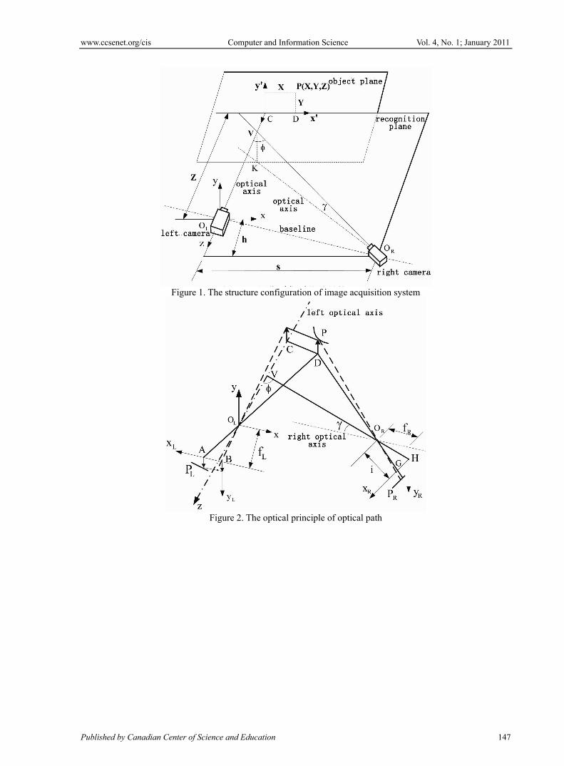
The structure configuration of image acquisition system is shown in figure 1. Figure 1 marks two optical axes, one is used for the acquisition of the left image and the other one is used for the acquisition of the right image. Assumed two opitical axes cut planes at two points close to each other, but not at a convergent point. In figure 1, the angle is used to mark the deviation between two optical axes.
The optical principle of optical path in image acquisition system in figure 1 is shown in figure 2.To take a random point P in the object plane, the left camera focus OL, the right camera focus OR and the point P are called “recognition plane”. The imaging point of the point P is PL in the left imaging system, and in the right imaging system, its imaging point is PR, which means that the point P images in the left and right imaging system is “a pair of image points”. The intersection line of the recognition plane and the plane where the measured object is gives a section here are the projective image elements of the two images. From the one dimension information of the left and right image points in the section, the depth information of the point P is obtained. In figure 2, baseline passes two lens’ focal line. To rotate recognition plane around baseline, by calculating each corresponding section’s optical path, the depth information of total surface of measured object is obtained.
The rectangular coordinates system in figure 2 is specified as follows:
Origin: Choose the focus of the left image acquisition system as origin.
z axis: Choose the optical axis of the left camera as z axis and specify the positive direction is from object to image. Therefore, x-y plane is parallel to the left camera’s image plane.
x axis, y axis: Specify x axis is located in recognition plane, optical axis is in the recognition plane and the direction of x axis from the left to the right. Then y axis and other directions are given correspondingly.
2. The selection of image coordinate system
The left camera image acquisition system coordinates are consisted of xL and yL axis, which is located in image plane and the origin is located in the center of image. xL and yL axis are parallel to x axis and y axis. Specify the positive direction of xL and yL axis accord to the negative direction of x axis and y axis.
2.1 In order to simplify calculations, redefine image coordinate system
In order to transform between image coordinate system (xL-yL) and the coordinate system (x-y-z) selected before, we specify that: the origin of image coordinate system (xL-yL) is located at the corner point of the left image in
coordinate system (x-y-z). Suppose the coordinate of certain image point is ( LL YX , ), ( MM YX , ) is the
coordinate of image point in the coordinate system (x-y-z), and then in the image coordinate system (xL-yL), the new coordinate of observation point is:
www.ccsenet.org/cis Computer and Information Science Vol. 4, No. 1; January 2011
Published by Canadian Center of Science and Education 143
)YY(Y
XXX
MLL
MLL
(1) The formula (1) is also applied to the right image coordinate system.
2.2 Optical axis is perpendicular to image plane
Now study the right camera’s image acquisition coordinate system. In the right camera’s optical system, the image coordinate axis xR and yR are still in image plane. xR axis is located in recognition plane, which contains optical axis of the left optical system meanwhile. Specify the positive direction of xR and yR are the same as that of xL and yL selected in the left camera’s coordinate system, and two optical axis are parallel. Through analysis we know that yR coordinate and yR axis are not important for calculation so we don’t consider them below.
Focal distance is defined as the distance from the right camera’s focus OR to image plane. Specified recognition plane doesn’t contain optical axis but contain xR axis. If the angle between right optical axis and recognition plane projection is ,
cos
fi R
O
(2) In the formula, fR is the focal distance of the right image acquisition system. From the formula 2 we can see, the distance iO is the function of optical system, irrespective of the sectionmeasured and selected. In order to calculate the point P in object plane, it’s necessary to study the optical path in recognition plane.
3. The space coordinates calculation of measured object points
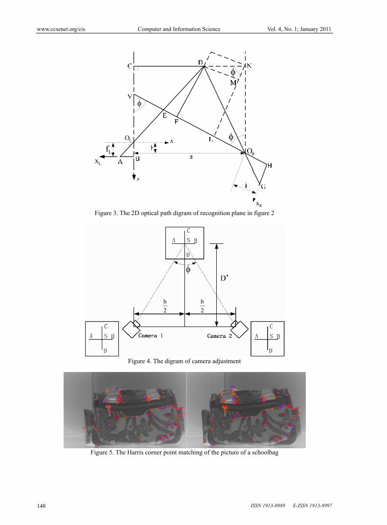
The figure 2 describes 3D optical path of optimal system. Now only to study the 2D optimal path of recognition plane in figure 2 and its diagram is given as shown in figure 3. The optical axis of the left camera’s image acquisition system is still in the 2D optical path. The direction of xL and xR is shown in figure 3. The geometric relationship in figure 3 is same to each section. In the next discussion, the geometric relationship analyzed is independent of recognition plane selected. When calculating other sections, if the angle between the optical axis in the left image acquisition system and recognition plane is given, associate with the former calculation formula.
Observe triangle ABOL and CDOL, and obtain
LL CO
CD
BO
AB
(3) or
z
x
f
x
L
L
(4)
Likewise, Observe triangle GHOR and FDOR, and obtain
RR FO
FD
HO
GH
(5)
sinDNcosNO
cosDNsinNO
HO
GH
R
R
R (6) or
sin)xs(cos)zh(
cos)xs(sin)zh(
i
x R
(7) Accordin to the formula (4) and (7), z coordinates are obtained as follows:
RLLRLRLR
RRRRL fxcosfxtan)ffcosxx(
sfcoshxtan)hfcossx(fz
(8)
www.ccsenet.org/cis Computer and Information Science Vol. 4, No. 1; January 2011
ISSN 1913-8989 E-ISSN 1913-8997 144
Accordin to the formula (4), x coordinates are calculated as follows:
Lx
f
zx
L
(9)
Similarly, y coordinates are obtained as follows:
Ly
f
zy
L
(10)
If the imaging magnification of the left camera’s optical system is
Lf
zv
(11) The formula (8) is substituted as follows:
RLLRLRLR
RRRR
fxcosfxtan)ffcosxx(
sfcoshxtan)hfcossx(v
(12)
So the coordinates of the point P in the coordinate system (x, y, z) are as follows:
L
L
L
vfz
vyy
vxx
(13) In order to further simplifies, we studied the optical equipment of figure 4. The digram in figure 4 is shown to adjust the camera. The distance AB is the midline of image, the adjustment point S images in the center of image. We may obtain:
22
2
bD4
bD4t
2tan1
2tan2
ttan
D2
b
2tan
bs
0
0h
(14) In the formula (14), b is the baseline, the distance from the adjustment point S to baseline is
D . If the camera chooses same parameters, the focal distance is:
fff LR (15) Therefore, imaging magnification is simplified to
)xx(ft)fxx(
)ftx(bv
RL2
LR
R
(16)
In the 3D geometric optical path shown in figure 3, the space coordinates can be calculated through either each corresponding point symetry coordinates in the left and right images of measured objects or the formula (13).
4. Discussion of the space coordinates of the blocked object points
For the object details visible partially, the coordinates in two images cannot be obtained and have no corresponding relations, which increases the difficult to recognize objects.
www.ccsenet.org/cis Computer and Information Science Vol. 4, No. 1; January 2011
Published by Canadian Center of Science and Education 145
Supposed the edge blocked partially is the transversal of two upper surfaces which are blocked partially. The
space position of the upper surface is determined by three angles in the surface. Take ( iii z,y,x )i=1,2,3, if (x, y,
z) is the point coordinate in the upper surface, three angles’coordinates are )z,y,x(E 1111 , )z,y,x(E 2222 ,
)z,y,x(E 3333 . Then the formula of the surface is:
0
zzyyxx
zzyyxx
zzyyxx
131313
121212
111
(17) Each surface’s coordinate is determined by three angles’ coordinates. Through obtaining the intersection coordinates of two upper surfaces, the 3D position of blocked edge is calculated.
If (x,y,z) is the coordinate of certain point blocked partially, there will be
0DzCyBxA
0DzCyBxA
2222
1111
(18)
In the formula, 1111 ,,, DCBA are the parameters of the first upper surface, and the specific parameters are
1111111
1313
12121
1313
12121
1313
12121
CzByAxDyyxx
yyxxC
xxzz
xxzzB
zzyy
zzyyA
(19) Similarly, 2222 ,,, DCBA are the parameters of the second surface.
Perpendicular to the surfaces (x,y) and (x,z), and the image projective surfaces which pass the blocked edge are (x,y) and (x,z).
The formula of the edge blocked partially in two projective surfaces is:
11
11
bxhz
axky
(20) In the formula, the parameters k1, a1, h1 ,b1 are:
2112
12211
2112
21121
1221
12211
1221
21121
CBCB
DBDBb
CBCB
BABAh
CBCB
DCDCa
CBCB
CACAk
(21)
The point of intersection of two lines is the position of angle. Given intersection line and chine line, the angle where the edge is cuts the intersection line. Supposed the position of the angle is ( eee ZYX ,, ), and
22
22
bxhz
axky
(22)
www.ccsenet.org/cis Computer and Information Science Vol. 4, No. 1; January 2011
ISSN 1913-8989 E-ISSN 1913-8997 146
In the formula 2222 h,k,b,a are constants.
Finally, the equation of the straight line is obtained as follows:
21
1221e
21
1221e
21
12e
hh
bhbhZ
kk
akakY
kk
aaX
(23) 5. The experimental results of stereo matching
Based on the discussion of the structure configuration of image acquisition system and the analysis of stereo coordinate calculation method above, CCD camera was used to do experimental reasarch on different objects (the selected objects are schoolbag and vase respectively). Two methods were choosen as follows: Harris corner point matching and SIFT feature matching. In order to intuitively show matching points, during Harris corner point matching, corresponding corner points of two images were marked the same numbers; during SIFT feature matching, corresponding feature points of two images are connected by straight lines.
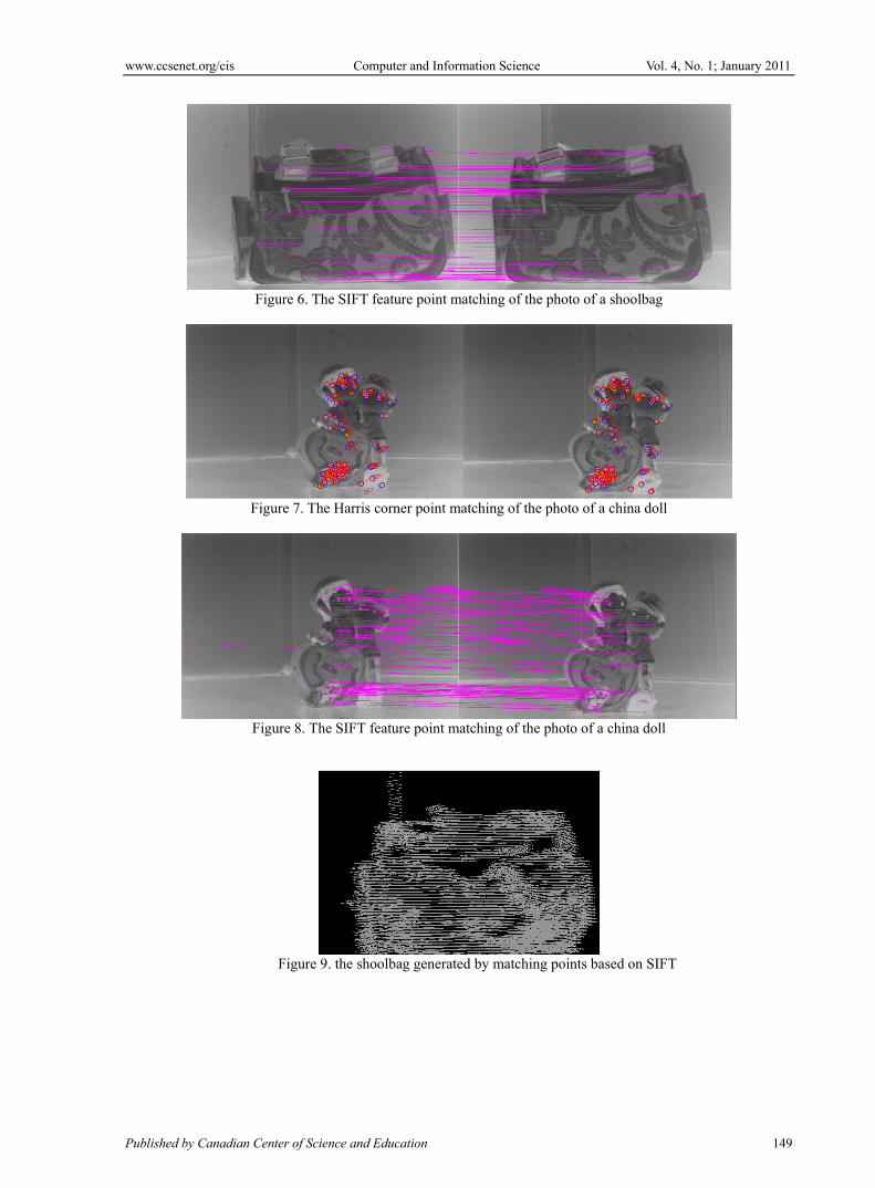
The effect figure that used Harris corner point matching for acquired shoolbag’s image is shown in figure 5. The effect figure that used SIFT feature point matching for acquired shoolbag’s image is shown in figure 6. The effect figure that used Harris corner point matching for acquired china doll’s image is shown in figure 7. The effect figure that used SIFT feature point matching for acquired china doll’s image is shown in figure 8.
Compared figure 5 with figure 6, in the first group of images, the number of matching points based on Harris corner point matching was equal basically to that based on SIFT feature point matching. Compared figure 7 with figure 8, in the second group of images, the number of matching points based on SIFT feature point matching was more than that based on Harris corner point matching obviously, but there were wrong matching points based on SIFT feature point matching. However, the two methods obtained better matching results.
Based on the calculation method and formula above, objects can be carried out stereo matching. Figure 9 and figure 10 are the images of shoolbag and vase respectively, which are generated by matching points based on SIFT feature matching.
6. Conclusions
The article discussed and studied the feature matching on visible absolutely object surface and visible partially object surface respectively and corresponding matching formula were obtained. It studied the structure configuration of image acquisition system and its optical path. In the experimental system developed, taking the images of schoolbag and vase for examples, making use of Harris corner point matching algorithm and SIFT matching algorithm achieved by VC++, 3D measurement experiment was carried out.
References
Fu, Liqin & Han, Yan. (2008). Study on Stereo Matching Technique for Digital Radiography Images. Journal of Image and Graphics.
Zhao, Cong, Qi, Xuepeng & Ke, Jing. (2008). Stereo Matching Algorithm Based on Control Points-Constrained and Area-Related. Journal of Shandong University of Technology(Natural Science Edition).
Zhou, Wenhui, Lin, Lili & Gu, Weikang. (2006). A Robust Algorithm for Real Time Stereo Match Based on Mutual Information. Chinese Journal of Sensors and Actuators.
Wang, Biao, Wang, Jinyan, He, Yizheng & Shen, Chunlin. (2005). A Novel Stereo Matching Algorithm. Computer Engineering.
Jiang, Shuhua. (2009). 2D(3D) Non-contact testing technique based on machine vision. Changchun University of Science and Technology.
Xing, Qingqing & Luo, Xinbin. (2009). Dege detection based on wavelet decomposition and labivew. Sichuan Nonferrous Metals.
www.ccsenet.org/cis Computer and Information Science Vol. 4, No. 1; January 2011
Published by Canadian Center of Science and Education 147
Figure 1. The structure configuration of image acquisition system
Figure 2. The optical principle of optical path
www.ccsenet.org/cis Computer and Information Science Vol. 4, No. 1; January 2011
ISSN 1913-8989 E-ISSN 1913-8997 148
LO
LxLf
Rx
RO
Figure 3. The 2D optical path digram of recognition plane in figure 2
Figure 4. The digram of camera adjustment
Figure 5. The Harris corner point matching of the picture of a schoolbag
www.ccsenet.org/cis Computer and Information Science Vol. 4, No. 1; January 2011
Published by Canadian Center of Science and Education 149
Figure 6. The SIFT feature point matching of the photo of a shoolbag
Figure 7. The Harris corner point matching of the photo of a china doll
Figure 8. The SIFT feature point matching of the photo of a china doll
Figure 9. the shoolbag generated by matching points based on SIFT

www.ccsenet.org/cis Computer and Information Science Vol. 4, No. 1; January 2011
ISSN 1913-8989 E-ISSN 1913-8997 150
Figure 10. the vase generated by matching points based on SIFT


![Binocular Photometric Stereo - duhao.org · Nehab et al. [14] use a laser-scanned shape to rectify the low frequency ... We propose a binocular photometric stereo setup in which a](https://img.pdfslide.us/doc/110x75/5ba1d30709d3f2716b8d33af/binocular-photometric-stereo-duhao-nehab-et-al-14-use-a-laser-scanned.jpg)