Embed Size (px)
Citation preview

Research on Electric Hydraulic Regenerative Braking System of Electric Bus
Xiaobin Ning Institute of Vehicle Engineering
Zhejiang University of Technology Hangzhou, China,[email protected]
Yangyan Guo Institute of Vehicle Engineering
Zhejiang University of Technology Hangzhou, China,[email protected]
Abstract—The target of this research is to make a study of the dynamics simulation about regenerative braking energy system of electric bus , and explore the feasibility of this system. Electric bus is rear axle drive and has rear-mounted biaxial parallel hydraulic hybrid system ,using AMESim software to establish the electric buses dynamics simulation model, the overall model is divided into two parts: the vehicle electrical driving system and hydraulic regenerative braking energy system.,they are coupling through the power coupler; PID control method is used to allocate the multi-system braking force; The results of simulation under ECE-15 cycle conditions show that the regenerative braking energy system can improve the efficiency of regenerative braking energy.
Keywords-brake; energy recovery; simulation
I. INTRODUCTION
The electric car has several advantages such as no emissions and no pollution, few noise, low running costs, especially in energy saving and environmental protection [1]. However,there have some technical problems in electric car waiting to be solved [2]. In order to solve those problems such as electric vehicle can't drive in long distance after one time's charging, regenerative braking energy recovery system is one of the best solution. Related to study abroad , electric vehicles on a single charge driving range can increase at least 10% to 30% with regenerative braking (braking energy recovery) system [3]. Due to the power density of hydraulic brake energy recovery system, be able to make up for the battery - the engine energy recovery system power density, hydraulic fuel-efficient cars began to be developed in the 1980s [4]. The developed hydraulic fuel-efficient cars in the world have different structures, based on the configuration of its powertrain combination, can be divided into series of structural forms, such as the secondary regulation hydrostatic drive system of the German company M.A.N Rexroth , which has simple structure and is easy to control different parameters of the system; the form of parallel structure, such as Sweden Volvo Cumulo drive system, which control link is simple, has little effect to automobile, and has high energy utilization efficiency; mixed-linked structural form, such as the Mitsubishi Company of Japan's CPS system, which has shown best energy-saving effect comparing with other forms, but the
system structure is complex and difficult to control [5].
The main target of this paper is to evaluate an electric bus design of hydraulic brake energy recovery system and establish an electro-hydraulic hybrid brake energy recovery system model with AMESim , after that we will carry on an analysis of the feasibility of regenerative braking system .
II. ESTABLISH THE DRIVING FORCE TRANSMISSION SYSTEM
MODEL ON AMESIM
A. Analysis of vehicle powertrain
The electric bus with rear mounted biaxially parallel hydraulic hybrid system (see Figure 1), having two drive sources, and the driving mode is rear axle drive. During modeling, the overall model is divided into two parts: the vehicle electrical driving system and hydraulic brake energy regeneration system. The modeling of vehicle driving force system can be divided into three sub-systems: battery - motor power source, power transmission and control system. The battery - the motors power source sub-model in AMESim, driven by the drive shaft when the battery does not discharge the motor rotation, can utilize braking energy to charge the battery, thus it can be regarded as a simple regenerative braking energy system of the electric energy storage.
1.Clutch pedal signal 2.Brake pedal signal 3.accelerator pedal signal 4. Mandatory relief signal 5 speed signal 6 main drive shaft 7 power coupler8. Clutch hydraulic 9.pump / motor 10 high-pressure accumulator 11 low-pressure accumulator 12. pressure sensor 13. fuel tank 14 oil filter 15 one-way valve 16. three four-way electro-hydraulic valve 17. normally closed two-way valve 18. pilot-operated relief valve 19 directly operated.
Figure 1. Electric bus electro-hydraulic hybrid system structure
Modeling of the electric bus, the vehicle model is simplified: ignoring the role of the suspension system in the Project supported by the National Natural Science Foundation of China
(Grant No. 51145015 ) and Foundation of Zhejiang Province Laboratory of Automobile Safety.
Proceedings of 2012 International Conference on Mechanical Engineering and Material Science (MEMS 2012)
© 2012. The authors - Published by Atlantis Press 231

braking process, i.e. there is no vertical movement among the vehicle, and excluding the load displacement from front and rear axles of the wheel suspension vibration generated ; DO not consider the situations that pitch and flip of the vehicle and the transmission of frictional losses.
B. To establish the vehicle driving force transmission system sub-model
In this paper, regenerative braking system and control systems are all required modeled in AMESim. The modeling process requires the mechanical library ,powertrain library and signal control repository. The pure electric vehicle powertrain model is shown in Figure 2.
Figure 2. Electric bus power transmission system model
To study the electro-hydraulic hybrid drive capability of the bus and the driving range, to meet the demand for electric vehicles powertrain model simulation analysis as a comparison. Transmission and rear axle main reducer are more complex mathematical model in reality, in this paper ,we only consider the speed ratio. Thus it can be replaced by using a simple model gear ratio. When braking of the vehicle occurs, a drive shaft of driveline shown in figure 1 driven by the motor rotation, and then charge the battery according to calculation module in AMESim, the pure electric vehicle driveline model establish in this paper is a simple electric regenerative brake systems.
C. Vehicle model parameter settings
The sub-model parameters is set according to the parameters of the system components and simulation. Those system parameters including the capacity of the battery and voltage, the motor torque and power, the ECU's minimum and maximum torque and braking requirements, the control parameters of the control system of the driver, the vehicle parameters, road condition parameters, etc., as well as simulation mode parameter settings. For example, the battery parameter settings: voltage is 388.8V, and capacity of 600AH, the initial depth of discharge DOD is 100%. Motor parameter settings: maximum motor power of 160kW, maximum torque of 1350Nm, motor efficiency 0.931, maximum speed 4500rev/min. Fill vehicle parameters settings in the parameter box. Road condition parameter setting the road cycle conditions, using driving cycle data file defined by user. The
driver control parameter settings of the control system is divided into acceleration control parameter and the brake control parameter, its parameter setting is the last one of the entire driveline. In simulation, they must be constantly adjusting parameters so that output speed curves of the system speed sensor could meet conditions closely . After setting the simulation required parameters, enter the simulation mode to set simulation parameters , Then simulation can be proceed. The simulation parameters of the system only set interval of simulation time and data processing. Other parameters will select the default value. Do ECE-15 condition simulation analysis in order to verify the accuracy of the simulation model established. The simulation results show that the vehicle speed curve and driving cycle curve are almost overlapped, indicating that the system model is accurate and reliable.
III. ESTABLISH THE ELECTRO-HYDRAULIC HYBRID
REGENERATIVE BRAKING ENERGY SYSTEM MODEL
A. Establish hybrid regenerative braking system To establish hydraulic regenerative braking system model
requires the hydraulic components library, control the signal component library and mechanical components of the library. The key part is to choose hydraulic components. There is no hydraulic pump / motor element model in AMESim hydraulic library so we build other components model to fulfill the hydraulic pump / motor function [6]. This article does not forced relief of simulation analysis, so instead of mandatory relief part of the hydraulic components can be used a direct-acting relief valve. The gear ratio module in mechanical library of AMESim can be created by a pair of meshing gear power coupler. Consolidated more sub-module design method, the final establishment of hydraulic regenerative braking system simulation model is shown in Figure 3.
Figure 3. Hydraulic regenerative braking system model
Fill the technical parameters in the parameter setting box according to the selected component models .
B. Establish electro-hydraulic hybrid system model Parallel automotive powertrain and hydraulic regenerative
braking system is connected by the power coupler , in AMESim submodel the two systems are connected by dynamic coupling, which are combined in a single electro-hydraulic hybrid regenerative braking system [7], As
232

shown in Figure 4. The key of simulation model operation is setting control signal. The electrical signals of the electro-hydraulic hybrid regenerative braking system consist of brake force distribution electrical signals and hydraulic system control signal. Other signals are constant.
Reasonable front and rear wheel braking torque distribution control is more complex, and the car is rear-wheel drive, so the system simulation control is rear brake mode. In separated rear wheel braking system, hydraulic regenerative braking system is to maximize the recovery of the braking energy. The rear electrical input of the system is zero, the front wheel is according to ECU braking requirements (output signal is braking intensity) so as to build a sub-module of the control signal. The front wheel control strategy is based on typical parallel braking energy recovery control strategies. The control method is shown in Figure 5 [8] [9].
Figure 4. Regenerative braking system with hydraulic of the power
transmission system simulation model
Figure 5 Electric hydraulic hybrid regenerative braking system brake control
method schematic diagram
When the vehicle is in condition of starting, accelerating and in the constant speed under a normal speed, the accumulator will release stored energy, and the pump / motor transformed it into mechanical energy to provide a driving force for the car. The energy release process control method of hydraulic regenerative braking system is shown in Figure 6.
Figure 6 .Acceleration control method of electric hydraulic hybrid
regenerative braking system schematic diagram
When the vehicle brakes, the pump is driven by the drive shaft. In order to provide the driver good sense of braking, it is necessary to control the flow of oil in the hydraulic pump / motor so that it will provide appropriate drag torque; during vehicle’ starting and the acceleration, the essential part of releasing stored energy is to make motor output torque or the rotational speed meet the change of the external load timely.
IV. REGENERATIVE BRAKING SYSTEM ANALYSIS AND
TYPICAL CONDITION ANALYSIS
A. Regenerative braking system analysis Figure 4 shows models of the braking energy recovery and
release simulation . The analysis of the hydraulic regenerative braking system's energy recovery capability and drive capability provide basis for the design of the regenerative braking system of electric bus.
Full load of running condition of motor vehicle:the vehicle is driven to 50km / h by motor and hydraulic regenerative braking system jointly , and then continue to travel 5s after parking brake, the brake strength is 0.1, braking and acceleration control strategy are according to Figure 5, 6 . The simulation results are shown below: Significance: Figure 7 and Figure 8 show that the vehicle with electro-hydraulic hybrid regenerative braking system enables to make acceleration time shorter during low speed, and the vehicle reaches the predetermined speed faster in the frequent starting process. Figure 9 and figure 10 curves show the design of the accumulator in this paper is completely meeting the actual demand, its stability is good and it has good practicability.
Figure 7. Vehicle speed contrast curve
233
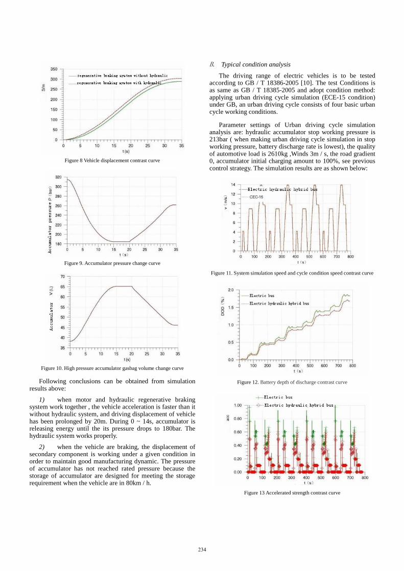
Figure 8 Vehicle displacement contrast curve
Figure 9. Accumulator pressure change curve
Figure 10. High pressure accumulator gasbag volume change curve
Following conclusions can be obtained from simulation results above:
1) when motor and hydraulic regenerative braking system work together , the vehicle acceleration is faster than it without hydraulic system, and driving displacement of vehicle has been prolonged by 20m. During 0 ~ 14s, accumulator is releasing energy until the its pressure drops to 180bar. The hydraulic system works properly.
2) when the vehicle are braking, the displacement of secondary component is working under a given condition in order to maintain good manufacturing dynamic. The pressure of accumulator has not reached rated pressure because the storage of accumulator are designed for meeting the storage requirement when the vehicle are in 80km / h.
B. Typical condition analysis The driving range of electric vehicles is to be tested
according to GB / T 18386-2005 [10]. The test Conditions is as same as GB / T 18385-2005 and adopt condition method: applying urban driving cycle simulation (ECE-15 condition) under GB, an urban driving cycle consists of four basic urban cycle working conditions.
Parameter settings of Urban driving cycle simulation analysis are: hydraulic accumulator stop working pressure is 213bar ( when making urban driving cycle simulation in stop working pressure, battery discharge rate is lowest), the quality of automotive load is 2610kg ,Winds 3m / s, the road gradient 0, accumulator initial charging amount to 100%, see previous control strategy. The simulation results are as shown below:
Figure 11. System simulation speed and cycle condition speed contrast curve
Figure 12. Battery depth of discharge contrast curve
Figure 13 Accelerated strength contrast curve
234

Figure 11 shows that electric hydraulic hybrid bus's speed curve has basically closed to speed of the conditions ECE-15, which indicates that braking performance regenerative braking system is stable; Figure 12 shows, the depth of discharge of electric hydraulic hybrid bus's battery is lower than electric bus ,if we calculated as a percentage of the battery discharge (battery discharge depth of 60 to 70%) , electric bus with hydraulic regenerative braking system on a single charge driving range145km, improve by 11km (8.2%); Figure 13 shows, for a not high average speed urban driving conditions, the torque provided by the secondary component has been basically meet the braking demand, mechanical friction of the electro-hydraulic hybrid bus work infrequetly so that it will greatly increase its friction pad longevity.
V. CONCLUSION AND DISCUSSION
In this paper, we model and simulate the electro-hydraulic regenerative braking system in AMESim. The electric bus drive systems, electric energy storage of braking energy recovery system and hydraulic regenerative braking system model, and using torque coupled submodels to connect two different simulation models, those elements composed of a mix of electro-hydraulic brake energy regeneration system model. Results of simulation analysis of brake energy recovery and release of the electro-hydraulic hybrid regenerative braking system model show that the simulation model has a certain value of the electric bus braking energy recovery system research and development. Results of simulation of the typical conditions show that single charge driving range of pure electric buses which equipped with the
hydraulic braking system has increase by about 8.2%, which indicating that the system has a certain energy recovery efficiency.
REFERENCES [1] Tan Yuanwen, Liu Li. Electric Vehicle Regenerative Braking System
Structure and Control Strategy. [J]. The Beijing car, 2007 (2): 15-18.
[2] Mei Xiaoan ,Zhang Naiping .World Electric Vehicle Technology Development and Trends [J]. Automotive research and development, 2004 (2): 19-23.
[3] Zhao Wenping .Pure electric Bus Regenerative Braking and Hydraulic Braking Coordinated Control Algorithm Research [D]. Jilin University,Changchun, 2008.
[4] Farhad Sangtarash, Vahid Esfahanian, et al. Effect of Different Regenerative Braking Strategies on Braking Performance and Fuel Economy in a Hybrid Electric Bus Employing CRUISE Vehicle Simulation[C]. SAE, 2008-01-156.
[5] Yimin Gao, Liping Chen and Mehrdad Ehsani. Investigation of the Effectiveness of Regenerative Braking for EV and HEV[C]. SAE, 1999-01-2910.
[6] Su Donghai, in Ganghwa. AMESim Hydraulic Simulation of New Technology and Its Application [J]. Applied Computer Technology, 2006, 33 (11): 35-37.
[7] Norio Nakazawa, ct al. Development of a Braking Energy Regeneration System for City Buses[R]. SAE, 872265.
[8] Xi Jianguo, Gao Zhen Ping, Chen Jie, Cao Junfeng. Regenerative Braking Energy System Based on AMESim Modeling Mechanical Design and Manufacturing [J]., 2010, 9: 65-67.
[9] Lynn Alfred, Smid Edzko, Eshraghi Moji, et al. Modeling Hydraulic Regenerative Hybrid Vehicles Using AMESim and Matlab/Simulink[J]. The International Society for Optical Engineering, 2005(5805): 24-40.
[10] GB / T 18386-2005, Electric Vehicles _ Energy Consumption Rate and Continued Driving Mileage _ Test Method [S].
235


![REGENERATIVE BRAKING SYSTEM IN ELECTRIC VEHICLES · REGENERATIVE BRAKING SYSTEM IN ELECTRIC VEHICLES ... REGENERATIVE BRAKING SYSTEM ... Regenerative action during braking[9]](https://img.pdfslide.us/doc/110x75/5adccef67f8b9a1a088c7cf0/regenerative-braking-system-in-electric-vehicles-braking-system-in-electric-vehicles.jpg)