Embed Size (px)
Citation preview
International Research Journal of Engineering and Technology (IRJET) e-ISSN: 2395 -0056
Volume: 03 Issue: 05 | May-2016 www.irjet.net p-ISSN: 2395-0072
© 2016, IRJET | Impact Factor value: 4.45 | ISO 9001:2008 Certified Journal | Page 1422
Solar Powered Electric Car with Regenerative Braking and Wireless Charging
Dr K S Badrinarayan1, Abhishek G2, Bhargav Tej Reddy2, Hashim Beary2, Premsagar. M2
1Principal, M S Engineering College, Karnataka, India 2Student, Dept. Of Mechanical Engineering, M S Engineering College, Karnataka, India
---------------------------------------------------------------------***---------------------------------------------------------------------
Abstract - Generally the braking system for a car is based on hydraulic braking technology. However, this traditional braking methodology causes a lot of energy wastage since it produces unwanted heat during braking. Thus, the invention of regenerative braking in electric car has overcome these disadvantages moreover it helps to save energy and provides higher efficiency for a car. In regenerative mode, the braking uses a generator; it transfers the kinetic to electrical energy to restore the batteries. The excessive energy from the rotational force that can be converted into electricity and fed back into the batteries during regenerative mode. The merits of regenerative braking over traditional braking are energy conservation, wear reduction, fuel consumption and more efficient transportation. Solar power is the conversion of sunlight into electricity using photovoltaic (PV). A vehicle powered significantly by light energy has a very large number of advantages. Nowadays, the brilliant technology in automotive industry towards regenerative braking and solar power is improving. In this paper, the working principle of regenerative braking have been studied to promote the efficiency and realization of energy saving in the electric vehicle along with the application of photovoltaics in them.
Key Words: Regenerative braking, generator, solar energy, energy conservation.
1.INTRODUCTION The invention of electric vehicle is a miracle, they are also known as green vehicles as it produces zero emission to the air which means there are no toxic gasses release from the car that causes the ozone layer depletion. Nowadays, the population of electric vehicles starts increasing according to the demand in the market. Besides, the enforcement by the government toward the production of electric car is getting more serious.
Every step is taken intensively by the world to save the Mother Nature from the excessive air pollution and the recession on the natural resources such as crude oils and natural gasses in the earth.
In twentieth century, vehicular technology such as control technology an integrative technology, have been developing aggressively. Somehow, the limitation of driving mileage still becomes an obstacle for the development of electric vehicles. This problem had been tackle by using regenerative braking
system, it has become one of the ways to improve the driving range as this method can increase an EV's driving range by 825%.
This technology had mostly replaced the traditional braking system in the cars because the traditional braking system always utilizes mechanical friction method to dissipate kinetic energy as heat energy in order to achieve the effect of stopping. Studies show that in urban driving, about one third to one half of the energy required for operation of a vehicle is consumed during braking.
Based on the energy perspective, the kinetic energy is a surplus energy when the electric motor is in the braking state since it dissipated the energy as heat and causes a loss of the overall energy. This wasted energy actually can be converted to a useful energy especially for the hybrid and electric car. Therefore regenerative braking had been implemented in the car braking system to recapture this wasted energy. In addition, the total energy saves is dependent on the driving condition, normally it is more effective in city driving rather than highway whereas little braking occurs.
There are several advantages of regenerative braking taken over the traditional braking system such as:
• More control over braking
• More efficient and effective in stop-and-go driving conditions
• Prevents wear on mechanical brake systems
• Better fuel economy
• Saves energy
In this work, the working principle and some braking controller for the regenerative braking have been reviewed.
2. REGENERATIVE BRAKING SYSTEM: 2.1 Working Principle
Regenerative braking is a braking method that utilizes the mechanical energy from the motor by converting kinetic energy into electrical energy and fed back into the battery source. Theoretically, the regenerative braking system can convert a good fraction of its kinetic energy to charge up the battery, using the same principle as an alternator. In
International Research Journal of Engineering and Technology (IRJET) e-ISSN: 2395 -0056
Volume: 03 Issue: 05 | May-2016 www.irjet.net p-ISSN: 2395-0072
© 2016, IRJET | Impact Factor value: 4.45 | ISO 9001:2008 Certified Journal | Page 1423
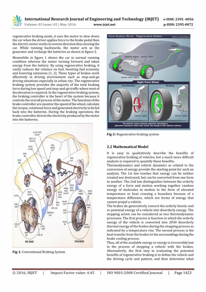
regenerative braking mode, it uses the motor to slow down the car when the driver applies force to the brake pedal then the electric motor works in reverse direction thus slowing the car. While running backwards, the motor acts as the generator and recharge the batteries as shown in figure 2.
Meanwhile in figure 1 shows the car in normal running condition whereas the motor turning forward and taken energy from the battery. By using regenerative braking, it vastly reduces the reliance on fuel, boosting fuel economy and lowering emissions (1, 2]. These types of brakes work effectively in driving environment such as stop-and-go driving situations especially in urban city. The regenerative braking system provides the majority of the total braking force during low speed and stop-and-go traffic where most of deceleration is required. In the regenerative braking system, the braking controller is the heart of the system because it controls the overall process of the motor. The functions of the brake controller are monitor the speed of the wheel, calculate the torque, rotational force and generated electricity to be fed back into the batteries. During the braking operation, the brake controller directs the electricity produced by the motor into the batteries.
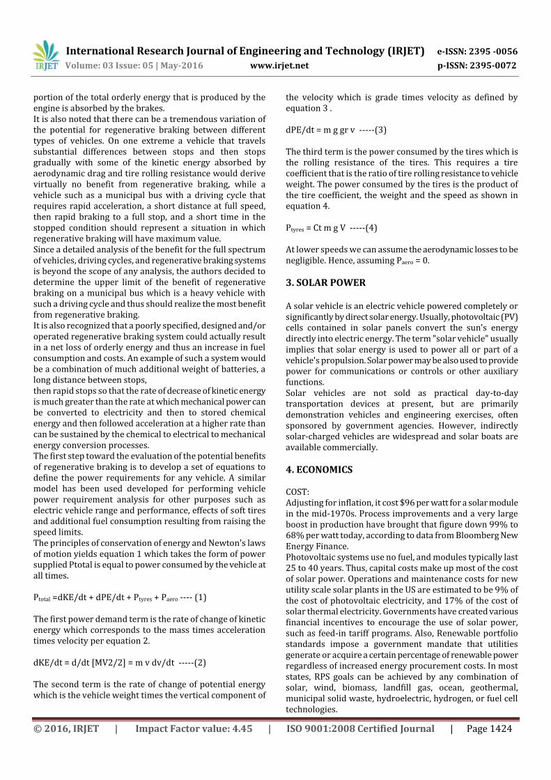
Fig-1: Conventional Braking System
Fig-2: Regenerative braking system
2.2 Mathematical Model
It is easy to qualitatively describe the benefits of regenerative braking of vehicles, but a much more difficult analysis is required to quantify these benefits. Thermodynamics and vehicle dynamics as related to the conversion of energy provide the starting point for such an analysis. The 1st law teaches that energy can be neither created nor destroyed, but can be converted from one form to another. The 2nd law distinguishes between the orderly energy of a force and motion working together random energy of molecules in motion in the form of elevated temperature or heat crossing a boundary because of a temperature difference, which are forms of energy that cannot propel a vehicle. The brakes de-generatively convert the orderly kinetic and or potential energy of a vehicle into disorderly energy. The stopping action can be considered as two thermodynamic processes. The first process is function in which the orderly energy of the vehicle is converted into 2030 disorderly thermal energy of the brakes during the stopping process as indicated by a temperature rise. The second process is the heat transfer from the brakes to the surroundings during the brake cooling process. Thus, all of the available energy or energy is irreversibly lost in the process of stopping a vehicle with the brakes. Alternatively, the first step in evaluating the potential benefits of regenerative braking is to define the vehicle and the driving cycle and pattern, and then determine what
International Research Journal of Engineering and Technology (IRJET) e-ISSN: 2395 -0056
Volume: 03 Issue: 05 | May-2016 www.irjet.net p-ISSN: 2395-0072
© 2016, IRJET | Impact Factor value: 4.45 | ISO 9001:2008 Certified Journal | Page 1424
portion of the total orderly energy that is produced by the engine is absorbed by the brakes. It is also noted that there can be a tremendous variation of the potential for regenerative braking between different types of vehicles. On one extreme a vehicle that travels substantial differences between stops and then stops gradually with some of the kinetic energy absorbed by aerodynamic drag and tire rolling resistance would derive virtually no benefit from regenerative braking, while a vehicle such as a municipal bus with a driving cycle that requires rapid acceleration, a short distance at full speed, then rapid braking to a full stop, and a short time in the stopped condition should represent a situation in which regenerative braking will have maximum value. Since a detailed analysis of the benefit for the full spectrum of vehicles, driving cycles, and regenerative braking systems is beyond the scope of any analysis, the authors decided to determine the upper limit of the benefit of regenerative braking on a municipal bus which is a heavy vehicle with such a driving cycle and thus should realize the most benefit from regenerative braking. It is also recognized that a poorly specified, designed and/or operated regenerative braking system could actually result in a net loss of orderly energy and thus an increase in fuel consumption and costs. An example of such a system would be a combination of much additional weight of batteries, a long distance between stops, then rapid stops so that the rate of decrease of kinetic energy is much greater than the rate at which mechanical power can be converted to electricity and then to stored chemical energy and then followed acceleration at a higher rate than can be sustained by the chemical to electrical to mechanical energy conversion processes. The first step toward the evaluation of the potential benefits of regenerative braking is to develop a set of equations to define the power requirements for any vehicle. A similar model has been used developed for performing vehicle power requirement analysis for other purposes such as electric vehicle range and performance, effects of soft tires and additional fuel consumption resulting from raising the speed limits. The principles of conservation of energy and Newton's laws of motion yields equation 1 which takes the form of power supplied Ptotal is equal to power consumed by the vehicle at all times. Ptotal =dKE/dt + dPE/dt + Ptyres + Paero ---- (1) The first power demand term is the rate of change of kinetic energy which corresponds to the mass times acceleration times velocity per equation 2. dKE/dt = d/dt [MV2/2] = m v dv/dt -----(2) The second term is the rate of change of potential energy which is the vehicle weight times the vertical component of
the velocity which is grade times velocity as defined by equation 3 . dPE/dt = m g gr v -----(3) The third term is the power consumed by the tires which is the rolling resistance of the tires. This requires a tire coefficient that is the ratio of tire rolling resistance to vehicle weight. The power consumed by the tires is the product of the tire coefficient, the weight and the speed as shown in equation 4. Ptyres = Ct m g V -----(4) At lower speeds we can assume the aerodynamic losses to be negligible. Hence, assuming Paero = 0.
3. SOLAR POWER A solar vehicle is an electric vehicle powered completely or significantly by direct solar energy. Usually, photovoltaic (PV) cells contained in solar panels convert the sun's energy directly into electric energy. The term "solar vehicle" usually implies that solar energy is used to power all or part of a vehicle's propulsion. Solar power may be also used to provide power for communications or controls or other auxiliary functions. Solar vehicles are not sold as practical day-to-day transportation devices at present, but are primarily demonstration vehicles and engineering exercises, often sponsored by government agencies. However, indirectly solar-charged vehicles are widespread and solar boats are available commercially.
4. ECONOMICS COST: Adjusting for inflation, it cost $96 per watt for a solar module in the mid-1970s. Process improvements and a very large boost in production have brought that figure down 99% to 68% per watt today, according to data from Bloomberg New Energy Finance. Photovoltaic systems use no fuel, and modules typically last 25 to 40 years. Thus, capital costs make up most of the cost of solar power. Operations and maintenance costs for new utility scale solar plants in the US are estimated to be 9% of the cost of photovoltaic electricity, and 17% of the cost of solar thermal electricity. Governments have created various financial incentives to encourage the use of solar power, such as feed-in tariff programs. Also, Renewable portfolio standards impose a government mandate that utilities generate or acquire a certain percentage of renewable power regardless of increased energy procurement costs. In most states, RPS goals can be achieved by any combination of solar, wind, biomass, landfill gas, ocean, geothermal, municipal solid waste, hydroelectric, hydrogen, or fuel cell technologies.
International Research Journal of Engineering and Technology (IRJET) e-ISSN: 2395 -0056
Volume: 03 Issue: 05 | May-2016 www.irjet.net p-ISSN: 2395-0072
© 2016, IRJET | Impact Factor value: 4.45 | ISO 9001:2008 Certified Journal | Page 1425
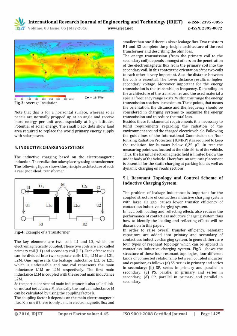
Fig-3: Average Insulation Note that this is for a horizontal surface, whereas solar panels are normally propped up at an angle and receive more energy per unit area, especially at high latitudes. Potential of solar energy. The small black dots show land area required to replace the world primary energy supply with solar power.
5. INDUCTIVE CHARGING SYSTEMS The inductive charging based on the electromagnetic induction. The realization takes place by using a transformer. The following figure shows the principle architecture of such a real (not ideal) transformer.
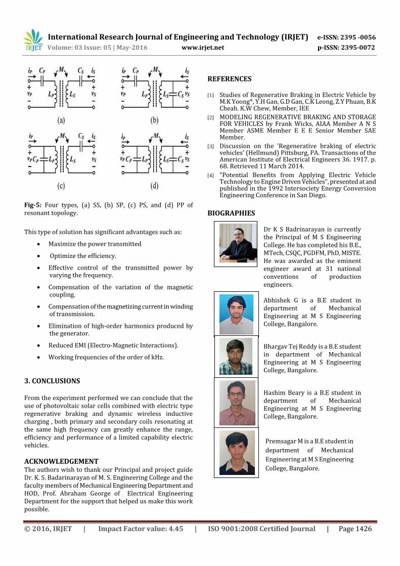
Fig-4: Example of a Transformer The key elements are two coils L1 and L2, which are electromagnetically coupled. These two coils are also called primary coil (L1) and secondary coil (L2). Each of these coils can be divided into two separate coils L1L, L1M and L2L, L2M. One represents the leakage inductance L1L or L2L, which is undesirable and one coil represents the main inductance L1M or L2M respectively. The first main inductance L1M is coupled with the second main inductance L2M. So the particular second main inductance is also called link- or mutual inductance M. Basically the mutual inductance M can be calculated by using the coupling factor k. The coupling factor k depends on the main electromagnetic flux. K is one if there is only a main electromagnetic flux and
smaller than one if there is also a leakage flux. Two resistors R1 and R2 complete the principle architecture of the real transformer and describing the ohm loss. The energy transmission (from the primary coil to the secondary coil) depends amongst others on the penetration of the electromagnetic flux from the primary coil into the secondary coil. In this context the orientation of the two coils to each other is very important. Also the distance between the coils is essential. The lower distance results in higher secondary voltage. Moreover important for the energy transmission is the transmission frequency. Depending on the architecture of the transformer and the used material a special frequency range exists. Within this range the energy transmission reaches its maximum. These points, that means the orientation, the distance and the frequency should be considered in charging systems to maximize the energy transmission and to reduce the total loss. Besides these fundamental requirements it is necessary to fulfill requirements regarding the radiation of the environment around the charged electric vehicle. Following the guidelines of the International Commission on Non-Ionizing Radiation Protection (ICNIRP) it is required to keep the radiation for humans below 6,25 µT. In test the measuring point was located at the side skirts of the vehicle. Thus, the harmful electromagnetic field is limited below the under body of the vehicle. Therefore, an accurate placement is essential for the static charging at parking lots as well as dynamic charging on roads sections.
5.1 Resonant Topology and Control Scheme of Inductive Charging System: The problem of leakage inductance is important for the coupled structure of contactless inductive charging system with large air gap, causes lower transfer efficiency of contactless inductive charging system. In fact, both loading and reflecting effects also reduces the performance of contactless inductive charging system thus how to identify the loading and reflecting effects will be discussion in this paper. In order to raise overall transfer efficiency, resonant capacitors are added into primary and secondary of contactless inductive charging system. In general, there are four types of resonant topology which can be applied in contactless inductive charging system. Fig.3 shows the structure of these four resonant topologies, four different kinds of connected relationship between coupled inductor and capacitor, as follows (a) SS, series in primary and series in secondary; (b) SP, series in primary and parallel in secondary; (c) PS, parallel in primary and series in secondary; (d) PP, parallel in primary and parallel in secondary.
International Research Journal of Engineering and Technology (IRJET) e-ISSN: 2395 -0056
Volume: 03 Issue: 05 | May-2016 www.irjet.net p-ISSN: 2395-0072
© 2016, IRJET | Impact Factor value: 4.45 | ISO 9001:2008 Certified Journal | Page 1426
Fig-5: Four types, (a) SS, (b) SP, (c) PS, and (d) PP of resonant topology.
This type of solution has significant advantages such as:
Maximize the power transmitted
Optimize the efficiency.
Effective control of the transmitted power by varying the frequency.
Compensation of the variation of the magnetic coupling.
Compensation of the magnetizing current in winding of transmission.
Elimination of high-order harmonics produced by the generator.
Reduced EMI (Electro-Magnetic Interactions).
Working frequencies of the order of kHz.
3. CONCLUSIONS From the experiment performed we can conclude that the use of photovoltaic solar cells combined with electric type regenerative braking and dynamic wireless inductive charging , both primary and secondary coils resonating at the same high frequency can greatly enhance the range, efficiency and performance of a limited capability electric vehicles.
ACKNOWLEDGEMENT The authors wish to thank our Principal and project guide Dr. K. S. Badarinarayan of M. S. Engineering College and the faculty members of Mechanical Engineering Department and HOD, Prof. Abraham George of Electrical Engineering Department for the support that helped us make this work possible.
REFERENCES [1] Studies of Regenerative Braking in Electric Vehicle by
M.K Yoong*, Y.H Gan, G.D Gan, C.K Leong, Z.Y Phuan, B.K Cheah. K.W Chew, Member, IEE
[2] MODELING REGENERATIVE BRAKING AND STORAGE FOR VEHICLES by Frank Wicks, AIAA Member A N S Member ASME Member E E E Senior Member SAE Member.
[3] Discussion on the 'Regenerative braking of electric vehicles' (Hellmund) Pittsburg, PA. Transactions of the American Institute of Electrical Engineers 36. 1917. p. 68. Retrieved 11 March 2014.
[4] "Potential Benefits from Applying Electric Vehicle Technology to Engine Driven Vehicles", presented at and published in the 1992 Intersociety Energy Conversion Engineering Conference in San Diego.
BIOGRAPHIES
Dr K S Badrinarayan is currently the Principal of M S Engineering College. He has completed his B.E., MTech, CSQC, PGDFM, PhD, MISTE. He was awarded as the eminent engineer award at 31 national conventions of production engineers.
Abhishek G is a B.E student in department of Mechanical Engineering at M S Engineering College, Bangalore.
Bhargav Tej Reddy is a B.E student in department of Mechanical Engineering at M S Engineering College, Bangalore.
Hashim Beary is a B.E student in department of Mechanical Engineering at M S Engineering College, Bangalore.
Premsagar M is a B.E student in
department of Mechanical
Engineering at M S Engineering
College, Bangalore.


![[PPT]Regenerative Braking Systems and their functions · Web viewHow Does Regenerative Braking Work? Regular brakes waste large amounts of useable energy6 Regenerative Braking systems](https://img.pdfslide.us/doc/110x75/5ae8634b7f8b9aee078f7805/pptregenerative-braking-systems-and-their-functions-viewhow-does-regenerative.jpg)

![REGENERATIVE BRAKING SYSTEM IN ELECTRIC VEHICLES · REGENERATIVE BRAKING SYSTEM IN ELECTRIC VEHICLES ... REGENERATIVE BRAKING SYSTEM ... Regenerative action during braking[9]](https://img.pdfslide.us/doc/110x75/5adccef67f8b9a1a088c7cf0/regenerative-braking-system-in-electric-vehicles-braking-system-in-electric-vehicles.jpg)