Embed Size (px)
Citation preview
~+ap!%gi, * SECURITY INFORMATION.d [ -.
copyRM E53A12
RESEARCH MEMORANDUM–
INVESTIGATION OF PRESSURE RECOVERY OF
A SINGLE-CONICAL-SHOCK NOSE INLET
AT MACH NUMBER 5.4
By Harry Bernstein and Rudolph C. Haefeli
Lewis Flight Propulsion LaboratoryCleveland, Ohio —
NATIONAL ADVISORY COMMITTEEFOR AERONAUTICS
WASHINGTONApril 6, 1953
.
.
--
IQNACA RM E53A12
NCD!-JCN
TECH LIBRARY KAFB. NM
0143423 ‘--”
●
NATIONAL ADVISORY COl@IITTEEFOR AERO~AUTICS
.
INVESTIGATION
RESEARCH MEMOIWJDUM:
OF FRMSUR3 RECOVERY OF A SING&CONICAL-SHOCK
NOSE INLET AT MACH NU14BIR5.4{
By Harry Bernstein and Rudolph C. &efelJ.
1
SUMMARY1
An experimental investigation of the performa+e of a single-conical-shock diffuser was conducted at a Mach nuuib;erof 5.4 and aReynolds nuniberbased on model dismeter of 375,000.! Total-pressurerecoveries of 13.7 and 13.1 percent were obtained 94 angles of attackof 0° and 3°) respectively. The corresponding kiqtic energy efficien-cies were 86.4 percent at an angle of attackan angle of attack of 3°.
. INTRODUCTION
~ recent years, consideration has been
of 0°
t-
86.0 percent at
I
I
Lgiven, o the possibility. of flight at speeds &my times that of soundj‘thatis
Mach nunibers.+ , at hypersonic-
A number of theoretical and experimental investigationsconcerned with the aerodynamics of wings and bodie at these flight l.kchnumbers have been remrted. %Some thought has also ,een given to thepower-plant requirements for hypersonic missiles.capable of providing sufficient thrust in the loweMachnunbers (~= 4 to 10) is the ram-jet engine.lytical and experimental information regarding theistics of the ram jet at these Mach numbers are me
An analytical investigation of ram-jet engineMch nuniberrange 3 to 7 is reported in referencea high-effi’ciencydiffuser (92-percent kinetic eneassumed to be available in order to estimate the mthat might be expected at these moderate hypersonivalidity of any assumptions upon which engine ~rfbe determined by experimental investigation. ●“Y
.To obtain an indication of the merits of a no
to ram-jet engines or auxiliary air supplies, an e. gation of the performance of a single-coni.csl-shoe
ri ong the enginesrange of hypersonicHoweverj both ana- 1
~perating character- :~er.I
Performance.in theFor this analysis
~ efficiency) wasximum performance:velocities. Thermance is based must
.*
e itiet for application,perimentalinvesti-diffuser designed for
2
a Mach nuniberof 5.4 was undertaken at theInasmuch as no effort was made to optimize
NACA W! E53A12
NAC!ALewis laboratory.the performance of the dif-
fuser by modifying the original design, the results herein arepreliminuy.
SYM80LS
The following symbols are used in this report:
stresm cross-sectional area
Mach nuniber
mass-flow rate
total pressure
angle of attack
ratio of specific heats
kinetic energy efficiency,
kinetic energy of air expanded isentropically from diffuserexit to free-strea st+tic pressure
free-stream kinetic energy
Subscripts:
o free-stresm tube entering inlet
1 combustion-chamber conditions
2 station of minimum area at diffuser exit
●
✎✎ �
-—
—
The testsflow hypersonic
APPARATUS
were conducted in the Lewis 6- by 6-inch continuous-tunnel at a Mach nuniberof 5.4. The test section total —
pressure was between 78 and 86 pounds per square inch absolute, with avariation of ~0.5 pound ~er square inch during any one run. The stag-nation temperature was 225~6° F.- These inlet conditions were sufficientto avoid condensation of the air components as evidencedby use of the .
light scattering technique described in reference 2. The test sectionReynolds number, based on an average total pressure of 83 pounds per
—
square inch absolute and on the model diameter, was 375,000..7
---ifA
NACA RM E53A12 3
●
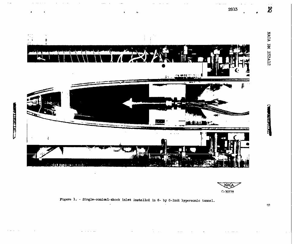
Figure 1 is a photograph of the tunnel showing the model in itstest position. The model was placed far up into the first test rhombus
. to avoid the effects of the large sidewall boundary layer due to second-ary flow in the nozzle (ref. 3).
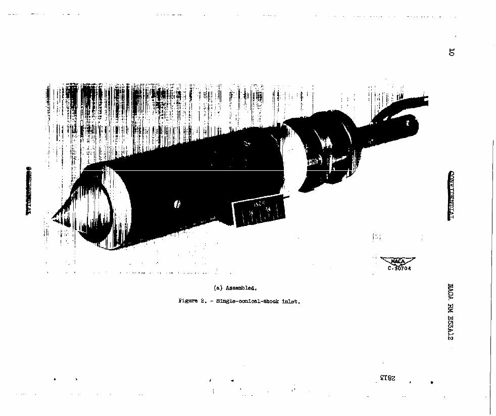
The model, shown in figures 2 and 3, was a single-conical-shocknose inlet with a design Mach number of 5.4. The theoretically optimumcone =-angle (27°) was determined by extrapolation from Mach nuuiber
N 5.0 of the calculations presented in reference 4. The internal angle
~ of the cowl lip was designed to cause an oblique shock in the diffuser0! entrance. The inlet had an internal contraction ratio equal to the
Kantrowitz ratio for the average Mach number behind this shock. Tomaintain a high mass flow, the cowl-lip external angle (31.9°) was keptless than the limiting angle for shock attachment at Mach number 5.4(41.50).
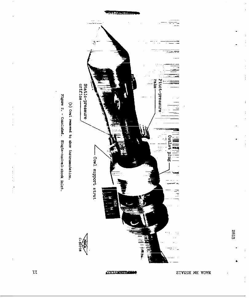
The instrumentation for measuring combustion-chsmber pressures isshown in figures 2(b) and 3. The eight pitot tubes were made fromO.OSO-inch outside diameter steel tubing with the openings flattened toinside dimensions of 0.002 by 0.040 inch. The three static orificeshad diameters of 0.021 inch. The pressures were read on a mercurymanometer.
The pitot and static probes described in reference 3 were used todetermine the free-stream conditions. The corresponding pressures were
? measured with mercury
.
The results of a
and butyl-phthslate manometers, res~ectively.
REDUCTION OF DATA
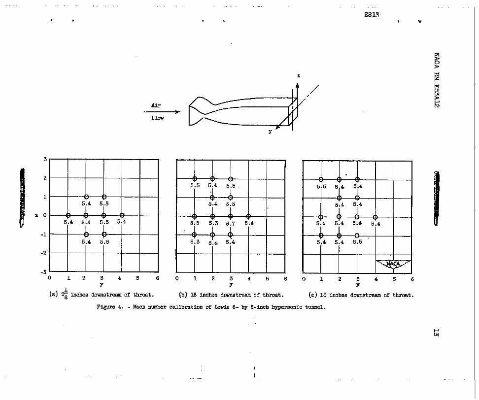
Mach number survey at three axial stations in thetest section of the Lewis 6- by 6-inch tunnel are presented in figure 4.
These stations were ~, 16, and 18 inches downstream of the tunnel-Z
throat; the cone tip of the model was located l% inches from the tunnel
throat. The Mach nunibers,determined by use of the Rayleigh equationfrom pitot and static pressure measurements, were reproducible within2 percent. Inasmuch as the variations from Mach nuniber5.4, indicatedin figure 4, are generally within the reproducibility, a nominal Machnumber of 5.4 was chosen for computations of diffuser performance. ~’
The test section pitot pressure was measured at locations appmxi- ~
mately 1 inch ahead of the nose of the model before each run. A valueof the free-stream total pressure was computed from these readings and
. from the normal-shock relation for Mach number 5.4.
.
4 NACA RM E52A12
The pressure recoveries of the model were based on an arithmetic*
average of the eight pitot-pressure readings in the combustion chamber.This method of averaging was believed to be sufficiently accurate, as
.
differences between the eight readings were, in most cases, less than.-
1/2 inch of mercury. Because of the unsymmetrical location of the pitottubes with the model at angle of attack, the pressures were measured atboth positive and ne~ative values of the same a, and the 16 pitotreadings were averaged in”the computation of the pressure recovery. Forthis method, the probable error in the maximum recovery is estimated tobe about 1 percent of its value. 3“
%The evaluation of diffuser mass-flow ratio was based on the average
of the three combustion-chamberstatic readings (six readings at angleof attack) and on a Mach nmiber computed from the ratio of the minimumexit area to the combustion-chamberarea +/Al. The sharp turning
angle”and subsequent flow separation or vena contracta at the exitnecessitated the application of a correction factor to the geometric
-
outlet areas. This factor was calculated to yield a mass-flow ratio ofunity when schlieren observations indicated that the inlet was capturingthe entire free-stream tube. For supercritical operation at angles ofattack of 0° and 3°, the correction factor increased monotonically from0.450 to 0.478 as the outlet area was increased. In the subcriticalrange the correction factor was assumed to have the value 0.450. As acheck on this method of mass-flow-ratio computation, effective combusti.on-
.-
chamber total pressures, based upon the measuredthe computed Mach ?.nuibers,were computed. Theseageement with the measured total pressures,
DISCUSSION OF RESULTS
static pressures and __pressures showed good v
..-
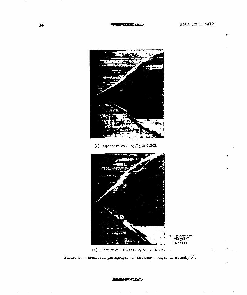
Schlieren photo~aphs of the flow configuration for the diffuser .—
at zero angle of attack are presented in figure 5. The boundary layeron the cone was observed to separate-and the mass flow through the inletwas therefore reduced. Subcritical operation of the diffuser, for thisconfiguration and all others to be discussed, was unstable (buzz).
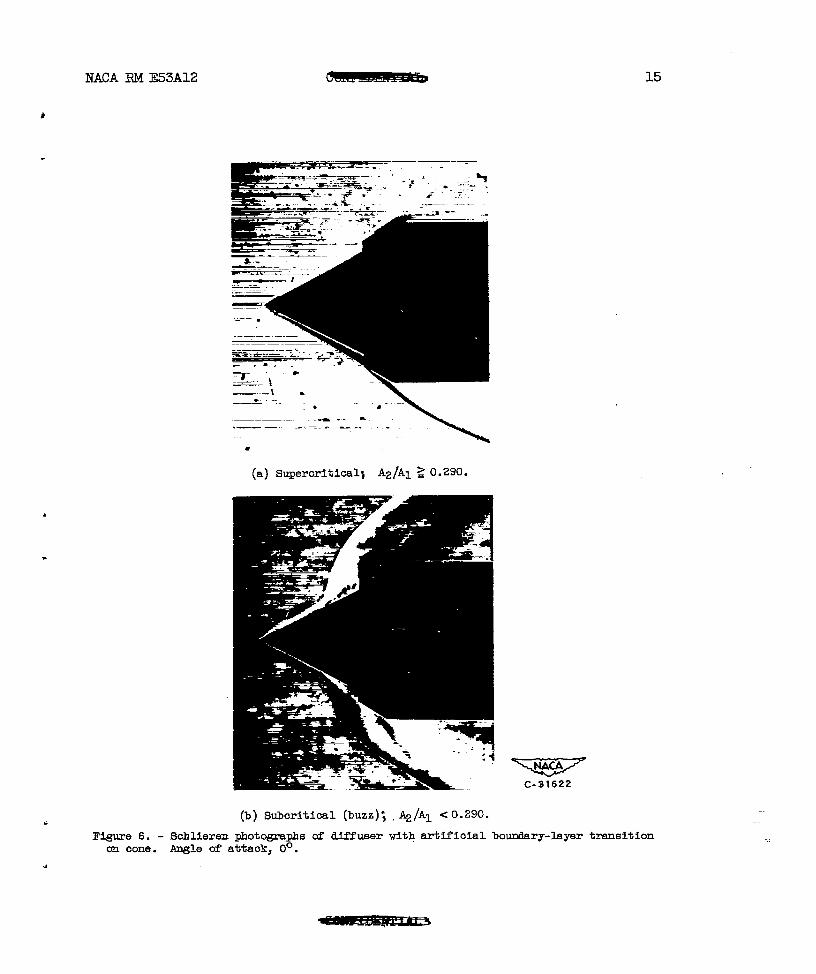
To avoid the boundary-layer separation, number 80 silicon carbidegrain was fixed to the tip of the cone to promote artificial transitionfrom a laminar to a turbulent boundary layer. Schlieren photographs ofthe diffuser with this artificial transition are shown in figure 6.The roughening of the cone tip was a sufficient measure to avoid sepa-
—
ration during supercritical diffuser operation. A slight mount of massflow, however, was still observed to be spilling over the cowl. Thisspillage was probably due to the effect of the greater displacementthickness of the turbulent boundary layer oh the cone surface, as com- .
pared with that of the laminar boundary layer assumed in the design ofthe diffuser. .
NACA RM E53A12 ~ 5
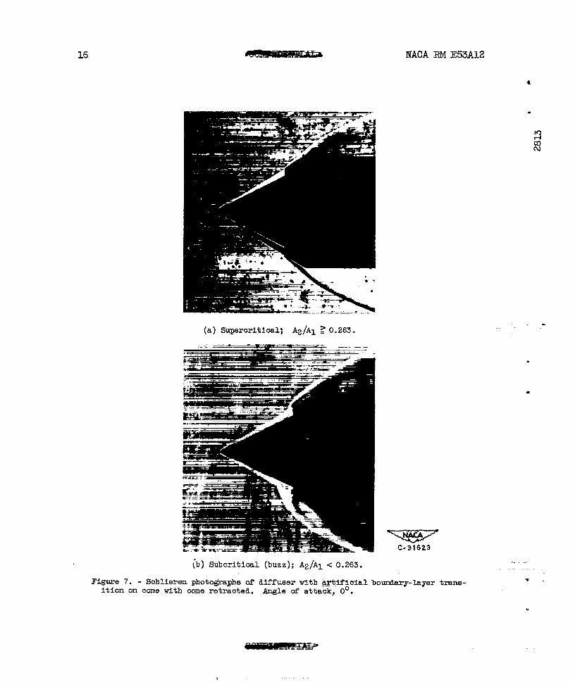
● So that all the mass flow would be captured, the cone was retractedinto the inlet a tistance of 0.01 inch. This distance was determinedfrom the schlieren photographs of figure 6 and represents the retraction.necessary to make the cone shock intersect the cowl leading edge.
Schlieren photographs of the diffuser with the cone retracted arepresented in figure 7. 1!% these and similar photographs it was deter-mined that the mass-flow ratio of the diffuser tien operating super-
ril critically was unity for W values of exit area. The exit area correc-CoP tion factors, discussed in the section REIKK3?IONOF DATA, were thereforew based upon the data for the inlet with the cone retracted and with arti-
ficial transition.
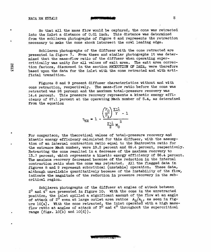
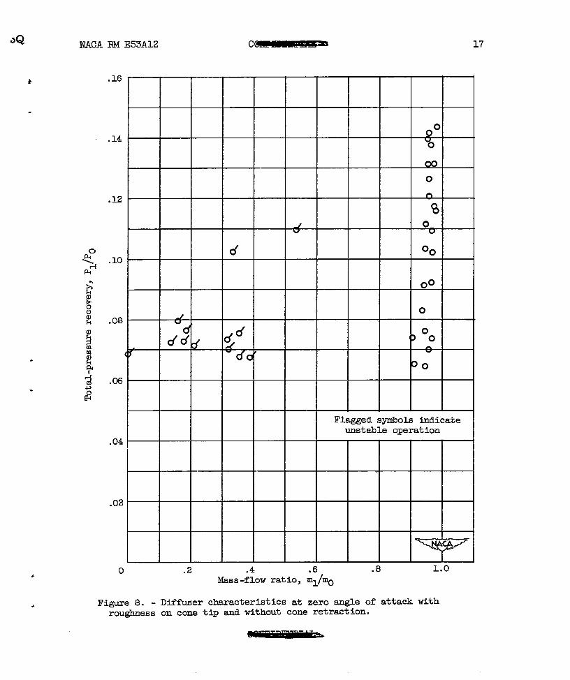
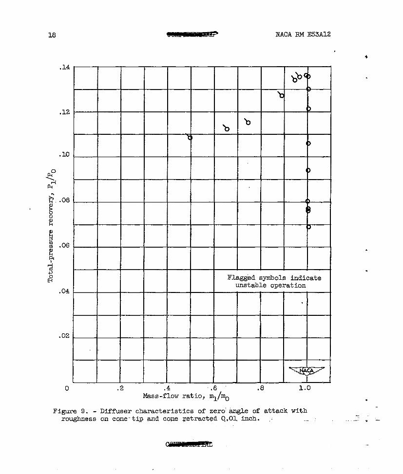
Figures 8 and 9 present diffuser characteristics without and withcone retraction, respectively. The mass-flow ratio before the cone wasretracted was 96 percent and the maximum total-pressure recovery was14.4 percent. This pressure recovery represents a kinetic energy effi-ciency of 87.1 percent at the operating Mach number of 5.4, as detemuinedfrom the equation
●
For comparison, the theoretical values of total-pressure recovery andkinetic energy efficiency calculated for this diffuser, with the assump-
. tion of an internal contraction ratio equal to the KAntrowitz ratio forthe entrance Mach nuniber,were 19.2 percent and 89.4 percent, respectively.Retracting the cone resulted in a decrease of the maxtiuunrecovery to13.7 percent, which represents a kinetic energy efficiency of 86.4 percent.The maximum recovery decreased because of the reduction in the internalcontraction ratio when the cone was retracted. All the flagged data infigures 8 and 9 represent subcritical (unstable) operation. These data,although unreliable quantitatively because of the instability of the flow}indicate the magnitude of the reduction in pressure recovery in the sub-critical region.
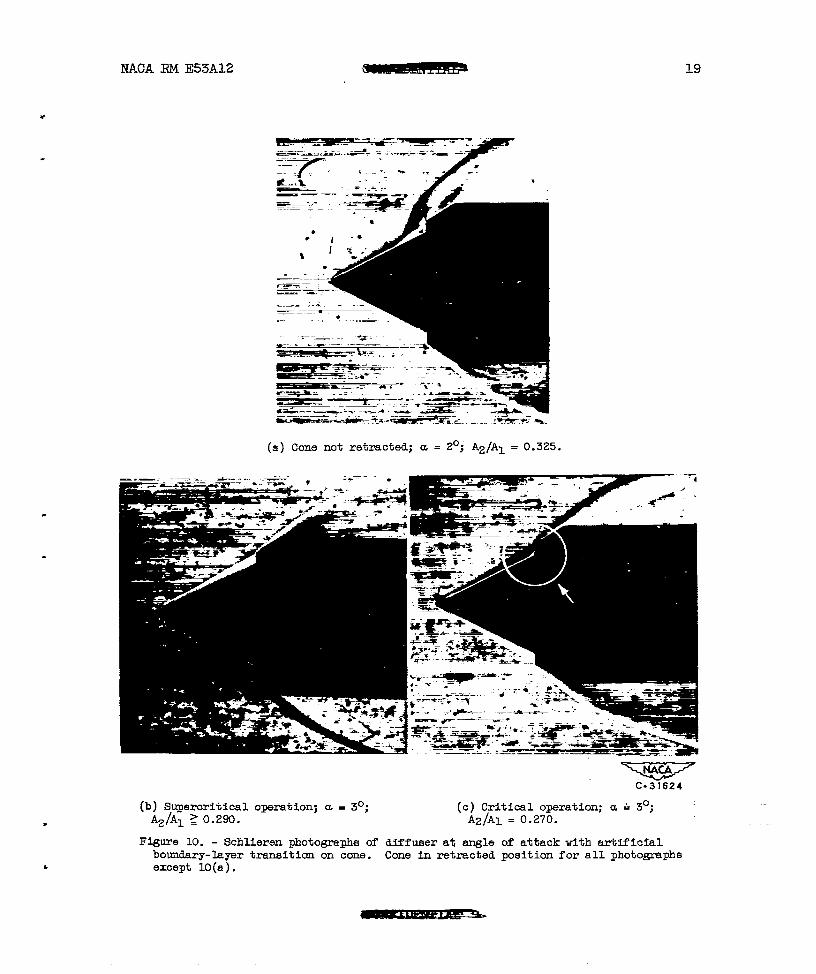
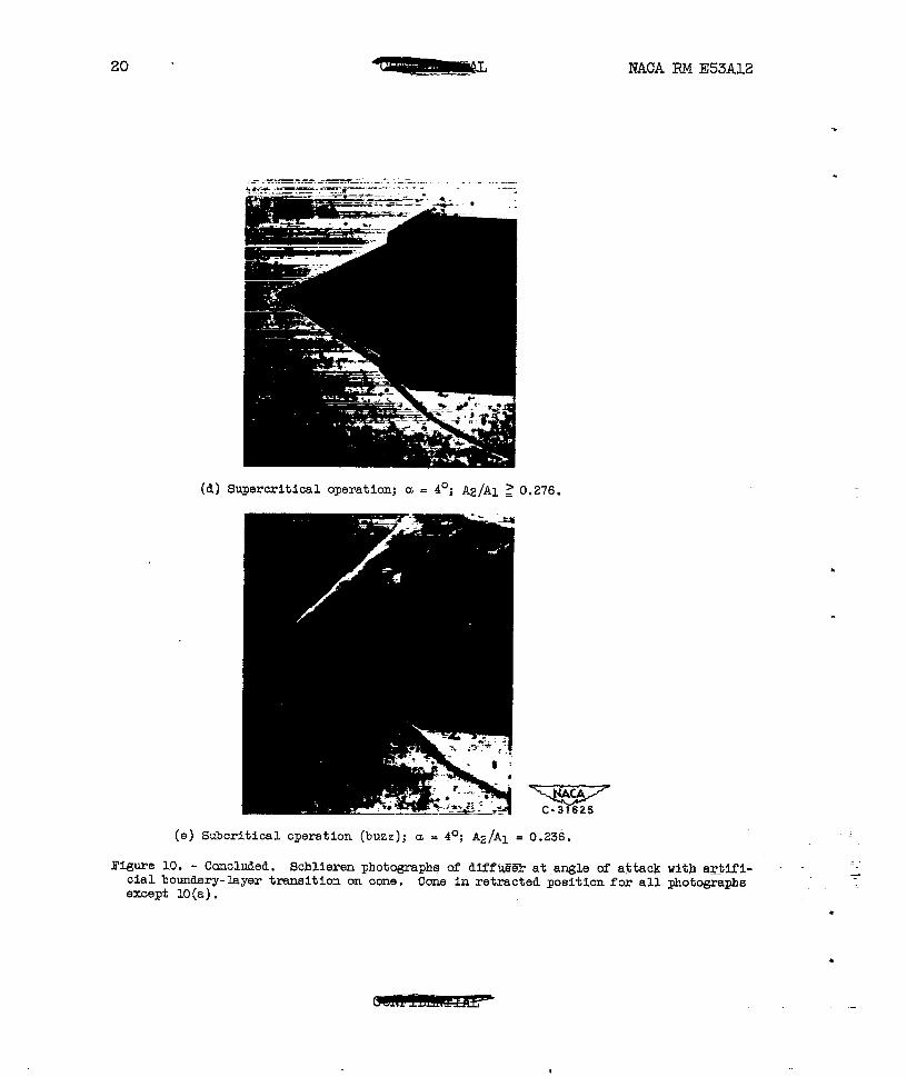
Schlieren photographs of the diffuser at angles of attack between2° and 4° are presented in figure 10. With the cone in tie wetractedposition, the inlet spilled a significant amount of the flow at an angleof attack of 2° even at large outlet area ratios ~/A , as seen in fig-ure 10(a). iWith the cone retracted, the inlet operate with a high mass-flow ratio at angles of attack of 3° and 4° throughout the supercritical
. range (figs. 10(b) and 10(d)).
.
6 NACA RM E53A12
For supercritical operation near maximum recovery, separation ofe
the boundary layer on the low pressure side tifthe cone (within circle,fig. 1O(C)) caused increased flow deflection upstream of the diffuserentrance. This resulted in the.formation of a bow wave in front of the
.
cowl in the region of the separation. A slight reduction in the mass-flow ratio therefore occurred.
—
The schlieren photograph presented in figure 10(e) for an angle ofattack of 4° illustrates the shock configuration typical for subcriticaloperation at all angles of attack (a= 2° to,40). The flow was com- m
1+pletely separated from the low-pressure side of the cone, while on the co
high-pressure surface the shock oscillated rapidly (buzz).N
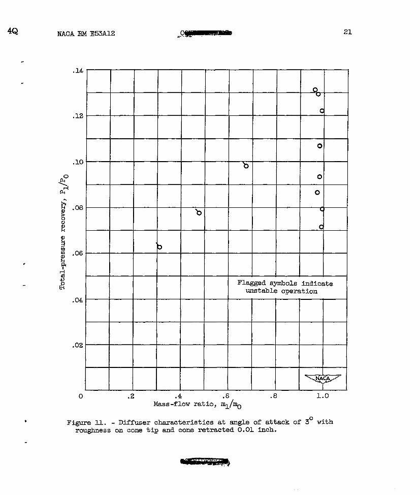
Diffuser characteristicsat an angle of attack of 3° are presentedin figure XL. A peak recovery of 13.1 percent (~~ = 86.0 percent) wasobtained. Both pressure recovery and mass-flow ratio were observed todecrease rapidly as the outlet area was decreased beyond that for criticaloperation (maximum recovery).
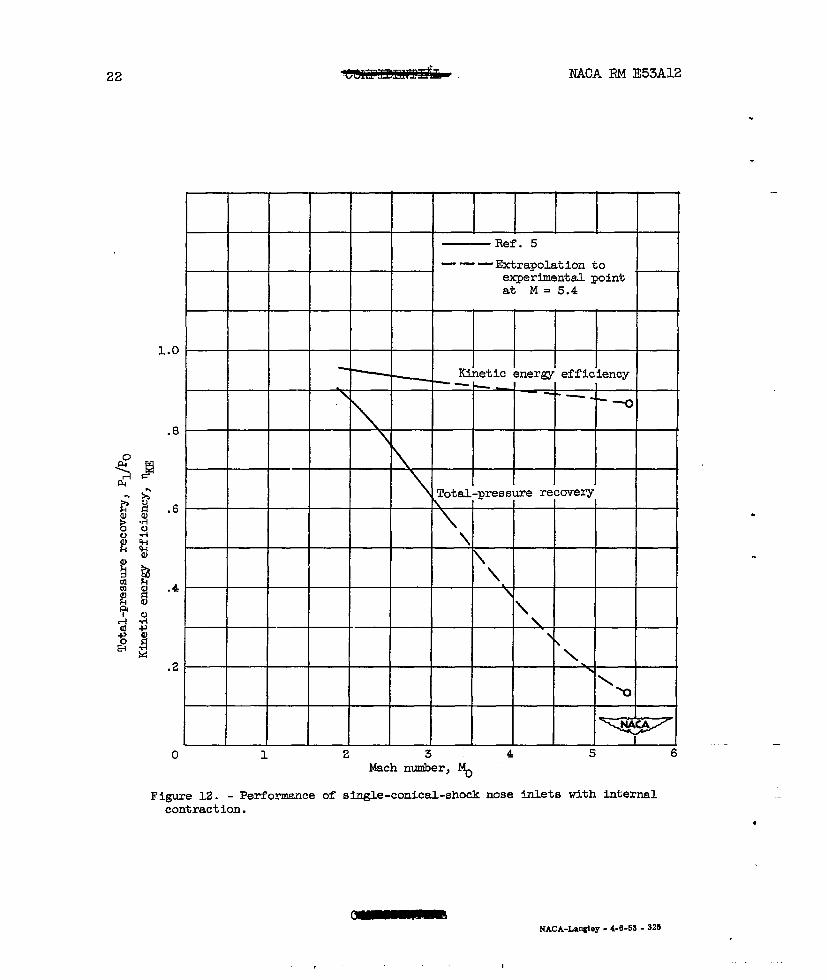
A performance comparison with similar inlets tested at lower Machnumbers (ref. 5) is presented in figure 12. The kinetic energy effi-ciencies of the diffusers decrease from 96 to 86 percent as the flightMach numbers increase from 1.85 to 5.4. Because the thrust coefficientof a ram-jet engine is proportional to the square root of kinetic energyefficiency, the assumption of a 92 percent q~, as made in the analysisof reference 1, results in no great error in the computation of thrust sfor Mach numbers up to 5.4.
— .—
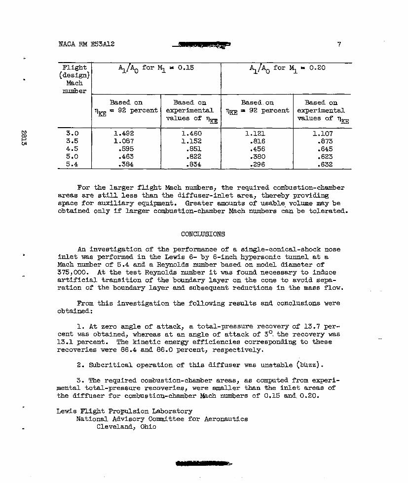
The combustion-chanibercross-sectionalarea of an engine is dependentupon the total-pressure recovery of the diffuser (continuity equation).For large l@ch numbers and corresponding experimentally probable values ofpressure recovery, small changes in kinetic energy efficiency result inlarge changes in total-pressure recovery. This is illustrated by thefact that a 92-percent efficiency represents a recovery of 27.2 percent,whereas an 86-percent efficiency represents a recovery of only 13.1 per-cent at a Mach nuuiberof 5.4. The combustion-chamberareas reported inreference 1 for q~ = 0.92 therefore differ considerably at the largerflight Mach numbers from those based upon experimental values of kineticenergy efficiency. This difference is shown in the following table fortwo values of combustion-chamberMach number:
.
●
✎
NACA RM E53A12 7
Flight(design]Machnumber
N 3.0~w 3.5
4.55.05.4
Based on Based on Based on Based onVm = 92 percent ellperimental Vm = 92 percent experimental
values of qm values of ~~
1.492 1.460 1.121 1.1071.087 1.152 ● 816 .873.595 .851 .456 .645.463 .822 .380 .623.384 .834 .296 .632
For the larger flight Mach nunibers,the required combustion-chamberareas are still less than the diffuser-inlet area, thereby providingspace for auxiliary equipment. Greater amounts of usable volume may beobtained only if larger combustion-chamber Mach numbers can be tolerated.
CONCLUSIONS
An investigation of the performance of a single-conical-shock nosez inlet was performed in the Lewis 6- by 6-inch hypersonic tunnel at a
Mach number of 5.4 and a Reynolds nuniberbased on model dismeter of375,000. At the test Reynolds number it was found necessary to induceartificial transition of the boundary layer on the cone to avoid sepa-ration of the boundary layer and subsequent reductions in the mass flow.
From this investigation the following results and conclusions wereobtained:
1. At zero angle of attack, a total-pressure recovery of 13.7 per-cent was obtained, whereas at an angle of attack of 30,the recovery was13.1 percent. The kinetic energy efficiencies corresponding to theserecoveries were 86.4 and 86.0 percent, respectively.
2. Subcritical operation of this diffuser was unstable (buzz).
3. The required combustion-chamber areas, as computed from experi-mental total-pressure recoveries, were smaller than the inlet areas ofthe diffuser for combustion-chamber Mach ntiers of 0.15 and 0.20.
-—
.Lewis Flight Propulsion Laboratory
National Advisory Committee for Aeronautics. Cleveland, Ohio
8 NACA RM E53A12
.
REFERENCES
1. Evans, Philip J., Jr.: Analytical Investigation of Rsm-Jet-Engine.
Performance in Flight Mach NuniberRange from 3 to 7. NACA RM E51H02> _ _ _—
1951.
2. Hansen, C. Frederick, and Nothwang, George J.: Condensation of Airin Supersonic Wind Tunnels and its Effect on Flow about Models.NACATN 2690, 1952. m
g3. Haefeli, Rudolph C.: Use of Fences to Increase Uniformity of
Boundary Layer on Side Walls of Supersonic Wind Tunnels.NACARM E52E19, 1952.
4. Moeckel, W. E., Connors, J. F.) and Schoeder~ A= H.: ~vestigationof Shock Mffusers at Mach Number 1.85. I - Projecting Single-Shock Cones. NACARME6K27, 1947.
5. Cortright, Edgar M.} Jr.j and Connors, James F.: Survey of somePreliminary Investigations of Supersonic Diffusers at High MachNwibers. NACARME52E20, 1952.
.
.
.
.
2813, . ,, * E
● -qqp)!!l,q ~i ..**”,?.. -,. a11
.~ ““ —
m
I —-——.. —,~@lMklimkLn II
Fisme 1. - Singl.e-omlcal-shook Inlet Jnatalled Jn 6- by 6-lMh h~rsodc tunnel,
co
‘1
I
1
,,, !
.,.!,.,., ,., ,, ...
(a) A8aembled,
Wwra 2. - 8~le-omdcal-shook imlet..
‘7%7
, .
1
‘2T8Z , ●
)’
-(T
--
-- —.—.—.,— —
.—. .. ..-
.—!., -+
.4 %1 ____
‘“’ ~ ij’-=
ZtVSS3 W VOVN
.
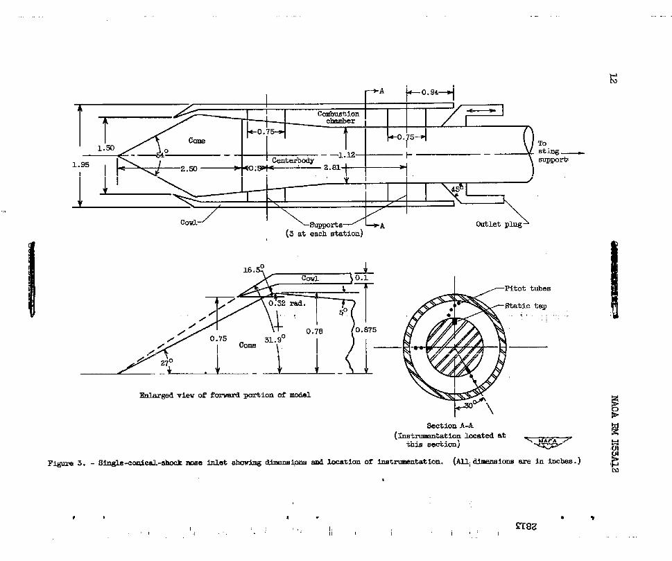
Enlmged view of fcnwrd portion of modal
Section A-A
(Imt rumntation I.ccated atthis section)
F@m 3. - Smgle-cm.ucd-llhock -e mot &x5ulng a.im=m @a ad location of Instrmmn taticm. (m, dlmamiom are in inches. )
1 ,,,‘, 4 .’ II I i I
,.I
“N
● 4 .
2813
3
2
1
%20
-1
-2
3-.
z
.w
5.4 6.5
. thw v
5.4 5.4 5.5 5.4
‘P ‘r5.4 5.5
0 12345 6
Y
(8) ‘+ iUC~E dOWllBtl’e.9Q Of thl%d .
\v v w5.5 6.4 5.5
v v5.4 5.5
& mw w ‘i-5.3 5.3 5.7 5.4
Y5.3 374 5.”4
Y’
01234”56
Y
(b) M inches downstream of throat.
w v -+5.5 5.4 5.4
‘+ Y5.4 5.4
m9 Y v5.4 5.4 5.4 5.4
‘w ‘# v5.4 5.4 5.5 “
0123456
Y
(C) 18 inches dowmtreem of thrmt .
F@ra 4. - &ch nmber celebration of IeviE 6- by 6-inch hyp?monic tumel.
14
Figure 5.
(a) Supercritioal;Az/AI>O.303.
l!Z4CARM E53A12
%
.
TC.31621
(b) Subcritical(buzz);K2/A1c 0.303.
Schlierenphotographsof diffuser. An@
.-. —
e & attack,OO.
NACA RM E!53A12 15
a- --—-—.-.——.. -——-1
.—
--- -—~. .-, -0 -.
——
q-
—..–1 *. -.——
--\
..- .s R ---
----.—— — ... —----- ... -
*
(a) Supercritioal; A2/Al Z 0.290.
(b) Subcritical(buzz); A2/Al < 0.z90.
FQure 6. - Schllerenphotograph d M.f’fuaerw5th artificialbomdary-leyeron cone. Angle of attack, 0°.
transition
-.--
16 NACA RM E53A12
4
(a) Su@roritioal; A2/Al 20.263.
.
.
=?3=’C-31623
{b) Subcritical(buzz);A2/AIc 0.263.
Figure 7. - Schlierenphot@caphs of Mffuaer %Lth &&tificialboundary-layertrans-ition on cone with cone retracted. Angle of attack, OO.
.
NACA RM E53A12
.16
.14
.12
.10
.08
.06
.04
.02
17
w I I
‘o
r I
+o
0/ o_ Iw
d 00
00
/ ou
# oC/d ~ k
I> 0(? o ‘
n
00
Flagged symibols indicateunstable operation
I J
#
Figure 8. -roughness
.2 .4 .6. .8 1.0
Mass-flowratio,ml/mo
Diffusercharacteristicsat zero angle of attack withon cone tip and without cone retraction.
NACA RM E53A12
.‘i
o
Figure 9. -roughness
b
b bx I
Flagged symbols indicateunstable operation
T
.2 .4 .6 .8 1.0Mass-flow ratio, ml/~
Diffuser characteristics of zero”Angle of attack withon conetip and cone retracted Q*O2 inch. .: ...
●
.
●
� u—
.-
NACA RME53A12 19
.
—-. ..-4
.—
4 -=%,..
—_ ——. -
●
●
+
.
. -—---=. .. .
--—- ,..;c------
%=*-- .“-.”z: .. ___ ___
~-_—+T .-,- .3
.Z
-,-, –—. -. .-., *
e.~ -: +.-– +.z..~ ,,!W.7’. %.
(s) Cone not retrmted; a = 2°; A2/Al =0.325.
=@&=C-31624
(b) Superoritioalopration; a=3°; (c) Critical operation;a = 3°;+/Al ~ 0.290. A2/AL = 0.270.
Figure 10. - Schlierenphotogx’apheof diffuserat angleboundary-layertransitionon cone. Cone in retractedexoept 10(8).
of attack wfth artificialpositionfor a11 photographs
20
Figurecialexoe~
1kIt
NACA RME53A12
(d) Supercritioaloperation;a = 4°; A2/Al 2C 1.276.
(e) Suboritioal operation (buzz); a=4°; A2/Al =
.0. - Concluded. Scblierenphotographsof dlffti-rIoundary-layertransitionon oone. Cone in retract10(a).
,
0.236.
at angle of atied poalticm for
a Ckall
Wit)lphotl
artifl->graph 0
.
●
.
—
4Q NACA RM E53A12 21
.
●
✎
.14
.12
.10
.06
.06
.02
0
u
Flagged symbols indicateunstable operation
.2 .4 .6 .8 1.0Mass-flow ratio, ml/+
Figure Il. - Diffuser characteristicsat angle of attack of 3° withroughness on cone tip and cone retracted 0.01 inch.
22 NACA RM E53A12
.
.
1.0
.8
.6
.4
.2
0
—Ref. 5
experimental pointat M = 5.4
Ki31etic energy efficiency
Total-pressure recovery
\
\
\b
11 2 3 4 5 6
Mach number, 1%
Figure I-2.- Performance of single-conical-shock nose inletswithLnternalcontraction.
.
.—
●
NAcA.~l,y -4.6-63-926
1